

Page 1

Gas Rotisserie Oven
MODEL DRGV (with TouchTEC Controller)
Operator’s Manual
NOTICE
The purchaser must post, in a prominent location, instructions to be followed
in the event the user smells gas. This information shall be obtained by
consulting the local gas supplier.
WARNING
Improper installation, adjustment, alteration, service or maintenance can
cause property damage, injury or death. Read the installation, operation and
maintenance instructions thoroughly before installing or servicing this
equipment.
FOR YOUR SAFETY
Do not store or use gasoline or other flammable vapors or liquids in the
vicinity of this or any other appliance.
SS-OM-051.02 9/02/15
Page 2

(864) 963-3471 • Toll Free: (800) 927-6887 • Fax: (864) 963-5316
WHAT IS
WHO IS
COVERAGE PERIOD
WARRANTY COVERAGE
EXCEPTIONS
EXCLUSIONS
INSTALLATION
REPLACEMENT PARTS
COVERED
COVERED
BKI LIMITED WARRANTY
2812 Grandview Dr. • Simpsonville, SC 29680 • USA
This warranty covers defects in material and workmanship under normal use, and applies
only to the original purchaser providing that:
អ The equipment has not been accidentally or intentionally damaged, altered or misused;
អ The equipment is properly installed, adjusted, operated and maintained in accordance
with national and local codes, and in accordance with the installation and operating
instructions provided with this product.
អ The serial number rating plate affixed to the equipment has not been defaced or
removed.
This
equipment purchased
អ Warranty claims must be received in writing by BKI within one (1) year from
date of installation or within one (1) year and three (3) months from data of
shipment from the factory, whichever comes first.
អ COB Models: One (1) Year limited parts and labor.
អ COM Models: Two (2) Year limited parts and labor. COM convection ovens also have a
two (2) year door warranty.
អ CO1 Models: Two (2) Year limited parts and labor. Five (5) Year limited door
warranty.
អ BevLes Products: Two (2) Year limited parts and labor.
អ Warranty period begins the date of dealer invoice to customer or ninety (90) days
after shipment date from BKI, whichever comes first.
This
warranty
e
xpenses
hours
travel time and
extended door warranty on convection ovens years 3 through 5 is a parts only warranty and
does not include labor, travel, mileage or any other charges.
អ Thermostat calibrations
អ Air and gas
អ Light
អ Glass doors and
អ Fuses,
អ Adjustments
អ Tightening
អ Failures
អ Unauthorized
អ Damage
អ Alteration,
អ Thermostats
អ Freight –
អ Ordinary
អ Failure to follow
អ Events
per
appropriate installation
installer, not the
BKI genuine
date of
warranty
covers on-site labor, parts and
of the
Any exceptions must be pre-approved in advance and in writing by BKI. The
អ Negligence
adjustments,
bulbs,
to
of screws or
caused
in
shipment,
misuse or
and safety valves with
other than normal UPS charges,
wear and
beyond control
Leveling, as well as
manufacturer.
Factory OEM parts receive a (90) day
installation
is
extended
for use in the U.S.A.
authorized
door adjustments,
burner
by erratic
repair by
installation and/or operating instructions,
by a BKI F
service
performed during regular, weekday business hours.
or acts of
after (30) days
flames and
fasteners,
voltages
anyone other than
improper installation,
tear,
of the
company.
proper installation
and use materials – is the responsibility of the
actory Authorized
to the original
representative
God,
from equipment installation date,
cleaning of
or gas
broken
purchaser
reasonable
suppliers,
a BKI F
capillary tubes,
and check out of all
Service
travel
up to (100) miles
pilot
burners,
actory Authorized
materials warranty
Center.
and applies only to
time
and travel
round
trip and (2)
Service Center,
new equipment -
dealer
effective from the
or
SS-OM-051.02 9/02/15
Page 3

Table of Contents
Table of Contents ........................................................................................................................................ 1
Introduction ................................................................................................................................................. 2
Safety Precautions .................................................................................................................................... 2
Safety Signs and Messages ................................................................................................................. 2
Specific Precautions ............................................................................................................................. 3
Safe Work Practices ............................................................................................................................. 4
Safety Labels ........................................................................................................................................ 5
Health and Sanitation Practices................................................................................................................ 5
Food Handling ...................................................................................................................................... 6
Storage of Raw Meats .......................................................................................................................... 6
Coding Cooked Foods .......................................................................................................................... 6
Storage of Prepared Foods .................................................................................................................. 6
Operation ..................................................................................................................................................... 7
Controls and Indicators ............................................................................................................................. 7
Hardware Controls................................................................................................................................ 7
Software Controls – Operation Screens ............................................................................................... 8
Software Controls – Programming Screens ....................................................................................... 10
Programming the Controller Using the Touchscreen Interface .............................................................. 12
Edit a Recipe ...................................................................................................................................... 12
Edit the Basic Setup ........................................................................................................................... 12
Operation with the Controller .................................................................................................................. 13
Viewing Recipes ................................................................................................................................. 13
Cooking .............................................................................................................................................. 13
Operation After a Gas or Power Outage ................................................................................................ 14
Normal Shutoff ........................................................................................................................................ 14
Installing Rotor System ........................................................................................................................... 14
Preparing and Loading Chickens ........................................................................................................... 14
Trussing Chickens .............................................................................................................................. 15
V-Spits ................................................................................................................................................ 16
Baskets ............................................................................................................................................... 17
Installation ................................................................................................................................................. 18
Unpacking and Handling ......................................................................................................................... 18
Location and Clearance .......................................................................................................................... 18
Specific Instructions ................................................................................................................................ 18
Counter Top and Stand .......................................................................................................................... 19
Mounting ................................................................................................................................................. 20
Stacking Ovens ....................................................................................................................................... 22
Locking Ovens in Place .......................................................................................................................... 27
Gas Supply Connection .......................................................................................................................... 28
Gas Manifold Pressure Test ................................................................................................................... 28
Maintenance .............................................................................................................................................. 29
Scheduled Maintenance ......................................................................................................................... 29
Daily Cleaning & Maintenance ........................................................................................................... 29
Troubleshooting ...................................................................................................................................... 32
Accessories ............................................................................................................................................... 33
Wiring Diagram .......................................................................................................................................... 34
Notes .......................................................................................................................................................... 35
SS-OM-051.02 9/02/15
Page 4

Rotisserie Oven Introduction
Introduction
Your BKI DRGV is a computer controlled gas rotisserie oven. It utilizes a double revolving mechanism
and infrared burner that ensure even product cooking. A touchscreen control and switches are provided
to allow for quick setup and operation. Removable components allow for easy maintenance and cleaning.
The BKI name and trademark on this unit assures you of the finest in design and engineering -- that it has
been built with care and dedication -- using the best materials available. Attention to the operating
instructions regarding proper installation, operation, and maintenance will result in long lasting
dependability to ensure the highest profitable return on your investment.
PLEASE READ THIS ENTIRE MANUAL BEFORE OPERATING THE UNIT. If
you have any questions, please contact your BKI Distributor. If they are unable to
answer your questions, phone the applicable BKI Technical Services Department:
BKI North America: (864) 963-3471
Safety Precautions
Always follow recommended safety precautions listed in this manual. Below is the safety alert symbol.
When you see this symbol on your equipment, be alert to the potential for personal injury or property
damage.
Safety Signs and Messages
The following Safety signs and messages are placed in this manual to provide instructions and identify
specific areas where potential hazards exist and special precautions should be taken. Know and
understand the meaning of these instructions, signs, and messages. Damage to the equipment, death or
serious injury to you or other persons may result if these messages are not followed.
This message indicates an imminently hazardous situation which, if not avoided,
will result in death or serious injury.
This message indicates a potentially hazardous situation, which, if not avoided,
could result in death or serious injury.
This message indicates a potentially hazardous situation, which, if not avoided,
may result in minor or moderate injury. It may also be used to alert against unsafe
practices.
This message is used when special information, instructions or identification are
required relating to procedures, equipment, tools, capacities and other special
data.
2
Page 5

Rotisserie Oven Introduction
The purchaser must post, in a prominent location, instructions
FOR YOUR SAFETY
Improper installation, adjustment, alteration,
service or
Specific Precautions
to be followed in the event the user smells gas. This information
shall be obtained by consulting the local gas supplier.
Do not store or use gasoline or other flammable vapors or
liquids in the vicinity of this or any other appliance
maintenance can cause property damage, injury or death. Read
the installation, operation and maintenance instructions
thoroughly before installing or servicing this equipment.
Use Gas Safely-- Avoid Danger
Gas can be a dangerous fuel if not handled safely.
Make sure to ventilate the oven properly. If the oven is not
properly ventilated, carbon monoxide can be released around
the oven. Asphyxiation or suffocation can occur if gas is not
ventilated properly.
Clearance to Combustibles
Observe proper clearance to combustibles as noted on the oven
rating tag. Never place anything on top of the oven.
Keep the area around the oven free and clear from combustibles.
WARNING – DANGEROUS VOLTAGE
This equipment uses high voltage. Serious injury can occur if
you or any untrained or unauthorized person installs, services,
or repairs this equipment. Always Use an Authorized Service
agent to Service Your Equipment.
Do Not Smoke Near the Oven
This oven uses combustible fuels to operate. Smoking near this
oven could possibly cause a fire. Do not allow anyone to smoke
near this oven.
3
Page 6

Rotisserie Oven Introduction
Wear Safe Clothing Appropriate To Your Job
Keep this manual with the Equipment
Protect Children
Safe Work Practices
Always wear your insulated mitts when handling hot oven parts or touch any
hot metal surface. If you lose or damage your mitts, you can buy new ones at
your local restaurant equipment supply store or from your local BKI
Distributor.
Always wear non-skid shoes when working around the oven or any other
equipment.
Never wear loose clothing such as neckties or scarves while operating this
equipment. Keep loose hair tied back or in a hair net while operating this
equipment.
Always wear appropriate personal protection equipment during the cleaning
process to guard against possible injury.
This manual is an important part of your equipment. Always keep it near for
easy access. If you need to replace this manual, phone the applicable BKI
Technical Services Department:
BKI North America: (864) 963-3471
Keep children away from this equipment. Children may not understand that
this equipment is dangerous for them and others.
NEVER allow children to play near or operate your equipment.
Keep Safety Labels Clean and in Good Condition
Do not remove or cover any safety labels on your equipment. Keep all safety
labels clean and in good condition. Replace any damaged or missing safety
labels. Refer to the Safety Labels section for illustration and location of safety
labels on this unit. If you need a new safety label, obtain the number of the
specific label illustrated on page 5, then phone the applicable BKI Technical
Services Department:
BKI North America: (864) 963-3471.
Be Prepared for Emergencies
Be prepared for fires, injuries, or other emergencies.
Keep a first aid kit and a fire extinguisher near the equipment. You must use
a 40-pound Type BC fire extinguisher and keep it within 25 feet of your
equipment.
Keep emergency numbers for doctors, ambulance services, hospitals, and
the fire department near your telephone.
Know your responsibilities as an Employer
• Make certain your employees know how to operate the equipment.
• Make certain your employees are aware of the safety precautions on the
equipment and in this manual.
• Make certain that you have thoroughly trained your employees about
operating the equipment safely.
Make certain the equipment is in proper working condition. If you make
unauthorized modifications to the equipment, you will reduce the function and
safety of the equipment.
4
Page 7

Rotisserie Oven Introduction
CONTROL SIDE of
Safety Labels
DANGER
HIGH VOLTAGE.
Turn power off before
servicing. May have more than
one disconnect switch.
HAUTE TENSION.
Mettez l'appareil hors tension avant
de proceder a l'entretien. Peut-etre
d'u commutateur de deconnexion.
BOTH SIDES of OVEN
For continued protection against risk of fire and
electrical shock, replace with 8 amp fuse only.
Pour la protection continuée le risque de feu et
la décharge électrique, remplace avec 8 fusible
d'Ampli seulement.
OVEN ONLY
WARNING
Do not cover or remove label
L'AVERTISSEMENT
Ne pas couvrir ou supprimer l'étiquette
N0658
MODEL
Modele
EQUIPPED FOR
Equipé pour
MANIFOLD PRESSURE
Pression le Collecteur
VOLTS
Minimum spacing to a wall or adjacent unit.
L'espacement minimum sur un mur ou unité
adjacente.
Minimum spacing above mounting surface.
L'espacement minimum au-dessus de la
surface de montage.
Suitable for installation on combustible floors.
Convient à l’installation sur un plancher combustible.
®
"Experts In Heat Transfer Technology"
www.bkideas.com
DRGV-7 123456789012-12345678
115
ANS Z83.11 • CSA 1.8-2007 Food Service Equipment
SERIAL NO
Nº de Serie
NATURAL
PHASE
GAS
Gaz
INCHES of WATER
4.5
Pouces d'eau
1
Hz
SIMPSONVILLE, SC, USA
DATE OF MANUFACTURE
DATE DE FABRICATION
12345678
INPUT
Énergie
60
AMPS / Ampère
72,000
BTU / Hr
BTU / H
Back
Arrière
Side
Côté
Bottom
Bas
N0656 -1
2.2
6
3
4
in.
in.
in.
Electrical Grounding Instructions
three-prong (grounding) plug for your protection against shock hazard and should be
plugged directly into a properly grounded three-prong receptacle. Do not cut or
remove the grounding prong from this plug.
Mise à la terre
mise à la terre assurant une protection contre les chocs électriques. La prise dans
laquelle elle est branchée doit être correctement mise à la terre. Ne pas couper ni
enlever la broche de mise à la terre de la fiche.
DO NOT COVER or REMOVE THIS LABEL NE RECOUVREZ PAS ou ENLEVEZ PAS CETTE ÉTIQUETTE
- Cet appareil est pourvu d’une fiche à trois broches dont une
CAUTION
- This appliance is equipped with a
AVERTIR
NORMAL OPERATION -
1.) Turn main POWER switch on.
2.) Touch controller screen to activate.
3.) Select desired cook recipe.
4.) Touch Cook or Preheat to start oven.
TO CANCEL COOK PROGRAM -
1.) Touch on upper right of controller
screen and hold for 3 seconds.
NORMAL SHUT DOWN -
1.) Cancel any activate cook program.
2.) Wait 30 seconds for fans to stop.
3.) Turn POWER switch off.
AFTER POWER or GAS OUTAGE -
the oven will shut of automatically.
To restart the oven, turn the POWER
switch off and wait 5 minutes.
Then follow NORMAL OPERATION
procedures above.
Lubricate rotor gears with BKI L0200
Lubricant each day after cleaning. Failure
to clean and lubricate the gears can
damage the drive motor or warp the gear
assembly.
DO NOT use caustic cleaners
when cleaning this unit.
! WARNING
WHEN LIT UNIT IS
MALFUNCTIONING.
TURN OFF and CALL
FOR SERVICE.
N0536
FONCTIONNEMENT NORMAL -
1.) Allumez INTERRUPTEUR principal.
2.) Écran tactile de commande pour activer.
3.) Sélectionner le programme de cuisson
désirée.
4.) Toucher Cook ou Preheat pour
commencer four.
D'ANNULER LE PROGRAMME de CUISSON -
1.) Toucher sur le contrôle et pendant
3 secondes.
ARRÊT NORMAL -
1.) Annuler le programme de cuisson actif.
2.) Attendre 30 secondes pour les fans
d'arrêter.
3.) Couper le courant interrupteur.
APRÈS MISE SOUS TENSION ou
de GAZ PANNE -
le four automatically arrêter.
Redémarrer le four, Couper le courant
interrupteur et attendre 5 minutes.
Puis suivre FONCTIONNEMENT
NORMAL procédure ci-dessus.
Lubrifier les engrenages du rotor avec BKI
L0200 lubrifiant chaque jour aprè
nettoyage. D
les engrenageseut peut endommager le
moteur d'entraînement ou dedéformer
l'engrenage.
LUBRICATE HERE
LUBRIFIEZ ICI
éfaut de nettoyer et lubrifier
NE PAS utiliser de nettoyants
caustique pour nettoyer cette unité.
FRONT of OVEN
5
N0657
Intended for other than household use.
Non destiné à l’usage domestique.
For installation under ventilation hood only.
Installer en dessous d’une hotte de ventilation seulement.
Improper installation, adjustment, alteration, service or
WARNING
maintenance can cause property damage, injury or
death. Read the installation, operating and
main-tenance instructions thoroughly before installing
or servicing this equipment.
L’installation, le réglage, la modification, la réparation
L'AVERTISSEMENT
ou l’entretien incorrect de cet appareil peut causer des
dommages matériels, des blessures ou la mort. Lire
attentivement les instructions d’installation, de
fonctionnement et d’entretien avant de procéder à son
installation ou entretien.
N0656 -2
NOTICE
When this appliance is installed with
casters, it must be installed with the
casters supplied, a connector complying
with either ANSI Z21.69 • CSA 6.16 and a
quick-disconnect device complying with
ANSI Z21.41 • CSA 6.9. It must also be
installed with restraining means to guard
against transmission of strain to the
connector, as specified in the appliance
manufacturer’s instructions.
AVIS
le
Les appareils sur roulettes doivent être
pourvus des roulettes fournies, d’un tuyau
de raccordement conforme à la norme
ANSI Z21.69 ou CAN/CGA-6.16 et d’un
raccord à débranchement rapide
satisfaisant les exigences de la norme
ANSI Z21.41 ou CAN1-6.9. Ils doivent
aussi être munis d’un dispositif de
retenue pour empêcher toute
transmission de tension au tuyau de
raccordement confromément aux
instructions du fabricant.
BACK of OVEN
Page 8

Rotisserie Oven Introduction
Health and Sanitation Practices
BKI Rotisserie Ovens are manufactured to comply with health regulations and are tested and certified to
NSF and FSA standards. You must operate the equipment properly, using only quality products and use
meat thermometers to insure meats are thoroughly cooked.
Food Handling
• Wash hands thoroughly in warm, soapy water after handling raw poultry or meats.
• Clean and sanitize all utensils and surfaces that have been in contact with raw products. Clean
and sanitize the meat forks or baskets between cooking.
• Never place cooked meats on the same surfaces used to prepare raw meats, unless the area
has been thoroughly cleaned and sanitized.
Storage of Raw Meats
• Designate an area or shelf strictly for the storage of all raw meats to be used in the rotisserie.
• Raw product must always be stored at temperatures below 38° F. (3° C.).
• Never store or mix raw foods above cooked foods, as this is a health hazard. The drippings from
raw foods contaminate cooked or processed foods.
• All chicken and chicken parts to be stored overnight must be thoroughly iced down and
refrigerated.
Coding Cooked Foods
All products cooked during the day should be sold the same day.
NOTE: It is not the intent of the rotisserie program to have unsold merchandise at the end of the cooking
day. Follow your company’s procedures for the handling of any leftover product.
Storage of Prepared Foods
• Cold foods should be kept at or below 38° F. (3° C.).
• Hot foods must be maintained to meet local health codes, usually a minimum 145° F. (63° C.).
6
Page 9

Rotisserie Oven Operation
Item #
Description
Function
Operation
Controls and Indicators
Hardware Controls
1
Rotor Switch
2
Main Power Isolator
Light
3
Main Power Switch Turns power to the entire unit
4
Analog Touchscreen
Controller
5
Cooling Fan
Indicator Light
Depressing the switch allows
the operator to “jog” the rotor
position when the door is
open. Releasing the switch
stops the rotor.
This light illuminates to
indicate that power is being
applied to the oven from the
Main Power Isolator (Circuit
Breaker).
on or off. When placed in the
on position, the Touchscreen
controller is powered, lights
illuminate and the rotor motor
engages (if both doors are
closed). When placed in the
off position, power is removed
from the entire unit.
Used for operation and
programming of the oven. A
built-in beeper is used to
indicate touchscreen presses
and other oven functions. It
has 15 programmable cooking
recipes.
This light illuminates to
indicate there is a malfunction
of the cooling fan in the
control compartment. Call a
qualified BKI service
technician to repair the oven.
The oven can still be operated
with when this light is
illuminated. However,
operating the oven for an
extended period of time may
result in oven failure and
damage to additional
components.
TouchTEC ________
4
3
2
1
5
Power
! WARNING
WHEN LIT UNIT IS
MALFUNCTIONING.
TURN OFF and CALL
FOR SERVICE.
OPERATOR SIDE
7
Page 10

Rotisserie Oven Operation
Screen Name
Screen
Description
Preheat
Software Controls – Operation Screens
Startup
Controller Off
Recipe
Selection
Recipe Settings
Preheat/Cook
Selection
Preheat
Appears when the Main Power Switch is placed in the on
position.
Appears after the Startup screen displays. This screen
Indicates that the controller is turned off. Touching anywhere
on the screen will turn the controller on and display the
Recipe Selection screen.
Displays a the list of available recipes. The up and down
arrow buttons move the highlight box from one recipe to the
next. Once the desired recipe is highlighted the user
touches the GO button to start the cook cycle. Touching the
X button for 3 seconds turns the controller off. Touching any
recipe will show the settings for that recipe.
Displays Preheat Temperature, Cook Temperature, Cook
Time, Hold Temperature and Cook To settings for a
selected recipe. Touching the up and down arrow buttons
scroll the screen to view more settings. Touching the X
button momentarily returns you to the previous screen.
Displays once the user highlights a recipe and touches the
GO button if the recipe has a preheat temperature
programmed. The user selects where to start the cooking
cycle by touching Preheat or Cook. Touching Preheat
displays the Preheat screen. Touching Cook displays the
Ready To Cook screen. If the Preheat temperature is set to
OFF the controller goes directly to the Ready To Cook
screen. The T button can be used to display the current
oven temperature. Touching the T button displays the
temperature, then automatically returns to the previous
screen in 2 seconds. Touching the X button momentarily
returns you to the previous screen.
Displays once the user touches the
Preheat/Cook Selection screen. The Preheat cycle heats the
cooking cavity up to the pre-defined preheat temperature.
Once this temperature is reached the unit automatically
switches to the Ready To Cook mode. A small highlighted
letter H will appear to the right of the temperature display to
indicate that the controller has energized the heating
elements. The absence of the letter H indicates that the
controller has de-energized the heating elements as the
oven temperature has reached the set temperature limit.
The T button works as described for the Preheat/Cook
Selection screen. Touching the X button for 3 seconds
returns you to the Recipe Selection screen.
option from the
8
Page 11

Rotisserie Oven Operation
Screen Name
Screen
Description
Cook
COOK
EXTRA
Ready to Cook
Cooking
Hold
Extra Cook
Displays once the user touches the
Preheat/Cook selection screen or once the preheat cycle is
finished or directly from the Recipe Selection screen if no
preheat temperature was programmed. When the
temperature is within 5° of the cook temperature the
controller will emit three 2 second beeps indicating that the
product can be loaded. The user places the product to be
cooked into the cooking cavity and touches the COOK
button to start the cooking process. If the door is opened
and/or the temperature drops below 25° below the preheat
temperature, the screen will flash and beep every 30
seconds until the COOK button is touched. The highlighted
letter H works as described for the Preheat screen. The T
button works as described for the Preheat/Cook Selection
screen. Touching the X button for 3 seconds returns you to
the Recipe Selection screen.
Displays once the
To Cook screen. This screen shows the cooking
temperature, the time remaining in the cook cycle, and the
elapsed time shown with the progress bar at the bottom of
the screen. Hold the X button for 2 seconds to stop the cook
in progress. The EXTRA button can be used to add more
cook time to the cycle. The cook cycle ends when the cook
time elapses. This is indicated by three 2 second beeps. If a
hold temperature was programmed then the Hold screen is
displayed. If no hold temperature was programmed then the
screen will flash and beep until touched. The highlighted
letter H works as described for the Preheat screen. The T
button works as described for the Preheat/Cook Selection
screen. Touching the X button for 3 seconds returns you to
the Preheat/Cook Selection screen.
Displays once the cook cycle is complete if a hold
temperature was programmed. This screen displays the
hold temperature (or nothing if set to OFF), and the elapsed
time in the hold mode. The EXTRA button is available here
so the product can be cooked for more time if required. The
highlighted letter H works as described for the Preheat
screen. The T button works as described for the
Preheat/Cook Selection screen. Touching the X button for 3
seconds returns you to the Recipe Selection screen.
Appears when the
Cooking or Hold screens. Use the up and down arrow
buttons to set the amount of additional cook or hold time in 5
minute increments. Touch the GO button to add the
additional time you set. Touch the X button to return to the
previous screen without adding any extra cook or hold time.
button is touched from the Ready
button is touched from the
option from the
9
Page 12

Rotisserie Oven Operation
Screen Name
Screen
Description
BASIC SETUP
COOK PROGRAMS
Software Controls – Programming Screens
Startup
Controller Off
Recipe
Selection
Program
Security
Program Mode
Selection
ENTER CODE
0 0 0 0
Appears when the Main Power Switch is placed in the on
position.
Appears after the Startup screen displays. Indicates that the
controller is turned off. Touching anywhere on the screen
will turn the controller on and display the Recipe Selection
screen.
Appears once the Controller Off screen is touched. Touch
any recipe for 3 seconds to enter the programming mode.
Touch the X button for 3 seconds to turn the controller off.
Appears upon entering the programming mode and is used
to enter a 4 digit passcode. When the controller is first
powered, 0000 is used to access the programming mode.
Upon subsequent access, if you don’t want to use a special
passcode but want to leave it 0000 just press the GO button.
If you do want to use a special passcode, configure one
using the Basic Setup screen. Use the left and right arrow
buttons to move the cursor under the digit to be changed.
The up and down arrow buttons increase or decrease the
digit as desired. Touch the GO button to submit the security
passcode. If the passcode is valid the Programming mode
Selection screen will appear. If the passcode is invalid the
Program Security screen will reappear showing the
passcode you entered. Touch the X button to return to the
previous screen.
Appears once a valid passcode is entered from the Security
screen. Touch the BASIC SETUP option to change basic
controller parameters. Touch the COOK PROGRAMS
option to change cook parameters for a specific recipe.
Touch the X button to return to the Recipe Selection screen.
Basic Setup
Recipe Edit
Selection
Appears when the
option is touched from
the Programming Mode Selection screen. Use this screen to
configure the controller to display temperature in Fahrenheit
of Centigrade, to use short or long beeps at the end of a
cook cycle and to modify the four digit passcode. The E in
the bottom right corner toggles between English and
Spanish on the display. Touch the X button to return to the
previous screen.
Appears when the
option is touched
from the Programming Mode Selection screen. This screen
is used to select the recipe you want to edit. Use the up and
down arrow buttons to highlight the recipe then touch the
EDIT button. Touch the X button to return to the previous
screen.
10
Page 13

Rotisserie Oven Operation
Screen Name
Screen
Description
EDIT
Recipe
Parameter
Selection
Recipe
Parameter Edit
Appears when a recipe is selected and the
touched from the Recipe Edit Selection screen. This screen
is used to select a specific recipe parameter to edit. Use the
up and down arrow buttons to scroll through the list of
parameters and touch the parameter you want to change.
Touch the X button to return to the previous screen.
Appears when a recipe parameter is touched from the
Recipe Parameter Selection screen. This screen is used to
edit a specific recipe parameter. The editable parameters
are: Recipe name, Preheat Temp, Cook Temp, Cook Time
and Hold Temp. The left and right arrow buttons are used to
move the cursor under the character to be changed. The up
and down arrow buttons changes the character as desired.
The Preheat Temp and Hold Temp parameters can be
turned off by scrolling the temperature below 150°. Touch
the SAVE button to save the changed parameter. Touch the
X button to abort all changes and return to the previous
screen.
button is
11
Page 14

Rotisserie Oven Operation
Programming the Controller Using the Touchscreen Interface
Use the procedures below to edit a separate recipe or to change the basic controller configuration.
Edit a Recipe
1. Turn on the Power Switch. The Startup screen will briefly appear then the Controller Off screen will
display.
2. Touch anywhere on the touchscreen. The Recipe Selection screen will appear displaying a list of
recipes.
3. Touch any recipe for 3 seconds. The Security screen will appear.
4. Use the up/down and left/right arrow buttons to enter the passcode and touch the GO button. The
Program Mode Selection screen will appear if a valid passcode is entered.
5. Touch the COOK PROGRAMS option. A Recipe Edit Selection screen will appear.
6. Highlight the recipe you want to edit using the up/down arrow buttons then touch the EDIT button.
The Parameter Selection screen will appear.
7. Use the up/down arrow buttons to view the recipe parameters and touch the parameter you want to
edit. The Parameter Edit screen will appear.
8. Change the parameter value using the left/right and up/down arrow buttons then touch the SAVE
button to save your changes. You will return to the Parameter Selection screen.
9. Repeat the process to change any other parameters.
10. Touch the X button as necessary to return to the Recipe Selection screen.
Edit the Basic Setup
1. Turn on the Power Switch. The Startup screen will briefly appear then the Controller Off screen will
display.
2. Touch anywhere on the touchscreen. The Recipe Selection screen will appear displaying a list of
recipes.
3. Touch any recipe for 3 seconds. The Security screen will appear.
4. Use the up/down and left/right arrow buttons to enter the passcode and touch the GO button. The
Program Mode Selection screen will appear if a valid passcode is entered.
5. Touch the BASIC SETUP option. A Basic Setup Selection screen will appear.
6. Touch the parameter that needs to be changed. A Basic Setup Parameter Edit screen appears.
7. Change the parameter value using the left/right and up/down arrow buttons then touch the SAVE
button to save your changes. You will return to the Basic Setup Selection screen.
8. Repeat the process to change any other parameters.
9. Touch the X button as necessary to return to the Recipe Selection screen.
12
Page 15

Rotisserie Oven Operation
Operation with the Controller
Use the procedures below to view a separate recipe or to activate a cook cycle using a one of the
preprogrammed recipes.
Viewing Recipes
1. Turn on the Power Switch. The Startup screen will briefly appear then the Controller Off screen will
display.
2. Touch anywhere on the touchscreen. The Recipe Selection screen will appear displaying a list of
recipes.
3. Use the up/down arrow buttons to highlight the recipe you wish to view then touch it. A Recipe
Settings screen will appear.
4. Use the up/down arrow buttons to view any settings for the recipe selected.
5. Touch the X button momentarily to return to the previous screen.
Cooking
1. Turn on the Power Switch. The Startup screen will briefly appear then the Controller Off screen will
display.
2. Touch anywhere on the touchscreen. The Recipe Selection screen will appear displaying a list of
recipes.
3. Use the up/down arrow buttons to highlight the recipe you wish to use then touch the GO button. If
a preheat temperature was programmed then the Preheat/Cook Selection screen will appear. If no
preheat temperature was programmed then the controller enters the Ready To Cook mode
displaying the Ready To Cook screen.
• If the Preheat/Cook Selection screen appears, do either of the following:
• Touch the Preheat option to enter the Preheat mode. The controller will display the
Preheat screen. Once the preheat temperature is reached the controller enters the Ready
To Cook mode.
• Touch the Cook option to enter the Ready to Cook mode.
Once the temperature is within 5° of the cook temperature in the Ready To Cook mode the
controller will emit three 2 second beeps indicating that the oven can be loaded with product.
4. Load the product into the oven. Use the Rotor Switch on the front panel to operate the rotors during
loading.
5. Close the door.
6. Touch the COOK button. The controller now enters the cook mode and displays the cooking
temperature, time remaining in the cook cycle and the elapsed time. If necessary, use the EXTRA
button to add more cook time to the cycle. At the end of a cook cycle the controller will emit three 2
second beeps and enter the Hold mode and display the Hold screen if a Hold temperature was
programmed. If a Hold temperature was not programmed the screen will flash and beep until
touched.
7. Open the oven door and check the product for proper internal temperature. If necessary, use the
EXTRA button to add more cook time.
8. Unload the product if it is done.
13
Page 16
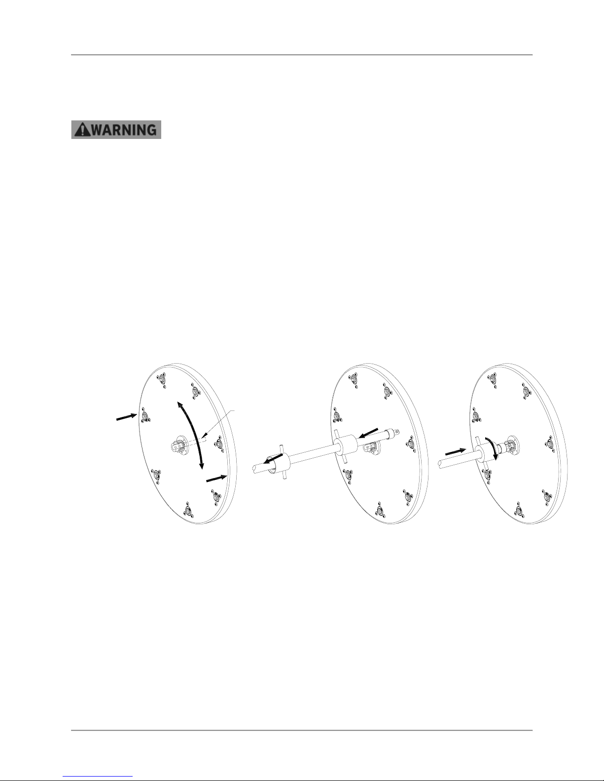
Rotisserie Oven Operation
STEP 1
engage the gears and the drive hub.
side.
STEP
2
Shaft ends must insert into the holes
STEP
3
ends of the shaft over the Rotor Disk
Operation After a Gas or Power Outage
The oven will shut off automatically if the gas supply is interrupted or the power goes out. If either of these
conditions occur you should perform the following procedure:
For your safety, if there is an interruption in the gas or power supply, make sure to
wait for at least five minutes before restarting your oven. This allows time for any
unburned gas to dissipate. (LP gas may take longer than five minutes.) If you
smell gas, do not start your oven.
1. Place the Main Power Switch to the “OFF” position.
2. Wait at least 5 minutes to allow gas that may have accumulated in the burner compartment to
escape.
3. Follow normal operating procedures once the power or gas is restored.
Normal Shutoff
1. Stop cooking and remove all food products from the oven.
2. Turn the Main Power Switch to the “OFF” position.
3. Allow oven cavity to cool before cleaning.
Installing Rotor System
ROTOR
GUIDE
PIN
Install the Rotor Disks by first
inserting the guide pin into the shaft
center hole. The Rotor Disk with
gears goes on the right side of the
oven. It will be necessary to rotate
this Rotor Disk while pushing in to
When properly installed there will be
approximately ¼” [6 mm] space
between the Rotor Disk and cavity
Rotate both Rotor Disks so that the
U-shaped slot in the hubs is facing
up and forward as shown. Grasp
the Rotor Shaft with both hands and
insert the ends into the U-shaped
hub slots. The pins in the Rotor
in the bottom of the U-shaped slots
in the Rotor Disk Hubs.
Slide the Rotor Shaft Nuts on both
hub and tighten by rotating the nuts
clockwise.
14
Page 17
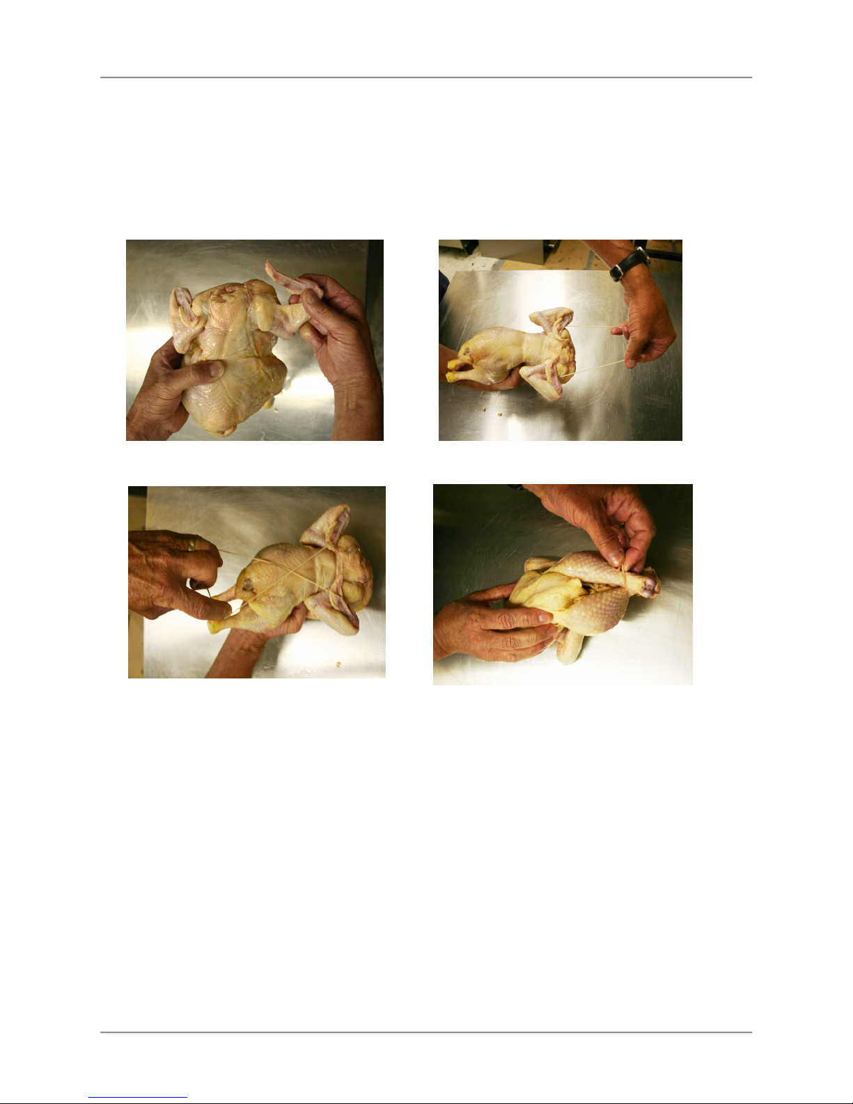
Rotisserie Oven Operation
Preparing and Loading Chickens
Trussing Chickens
It is recommended that whole chickens be trussed before cooking. Trussing holds the wings and legs of
the chicken tightly against the body. This improves the visual appeal of the chickens while they are
cooking. In addition trussing keeps the chicken moist by retaining more of the natural juices and helps
prevent the wing tips from burning.
Using 6 ½” – 7” elastic ties, follow these simple steps to truss the chickens.
1.
Fold wing tips back under the chicken
3.
Pull and twist the tie over the back of the
chicken to form an “X”. Make sure wing
tips are under tie
.
.
2.
With the back of the chicken up slip
the tie under the wings and pull back.
4.
Turn the chicken over and pull the tie
over the ends of the legs
.
15
Page 18

Rotisserie Oven Operation
STEP 1
STEP
2
Insert the square pin completely into
STEP
3
Verify that rotor disk slips into the
V-Spits
Up to four (4) whole chickens can be placed on a DRGV-7 v-spit. Insert the tapered (square pin) end of
the v-spit under the legs and through the cavity of the trussed chicken as shown below. Orient the spit
with the “V” toward the breast side of the chicken. The legs and thighs of the chicken should be on the
same side of the v-spit as the breast.
Make sure the chickens are evenly spaced on the v-spit. Do not place more than four chickens on a vspit. Chickens that are pushed tightly together on the v-spit will not brown properly during cooking leaving
“blonde” areas where the two chickens were touching.
The DRGV-7 will hold up to 7 v-spits. When loading less than 7 spits, space the spits as evenly as
possible on the rotors. Balancing the load on the rotors will extend the life of the rotor drive system.
When loading only 2 or 3 spits DO NOT place them in adjacent mounting locations on the rotors.
Load the first v-spit on the rotors as described below. Use the rotor jog button to advance the rotors while
loading additional v-spits.
Orient the V-spit with the round pin
to the left. Insert the round pin
completely into the hole in the
passive (left) side rotor.
Rotate the V-spit so that the flats of
the square pin align with the square
opening in the drive (right) rotor.
the square opening in the rotor.
16
slot in the round pin on the left end
of the V-spit.
Page 19
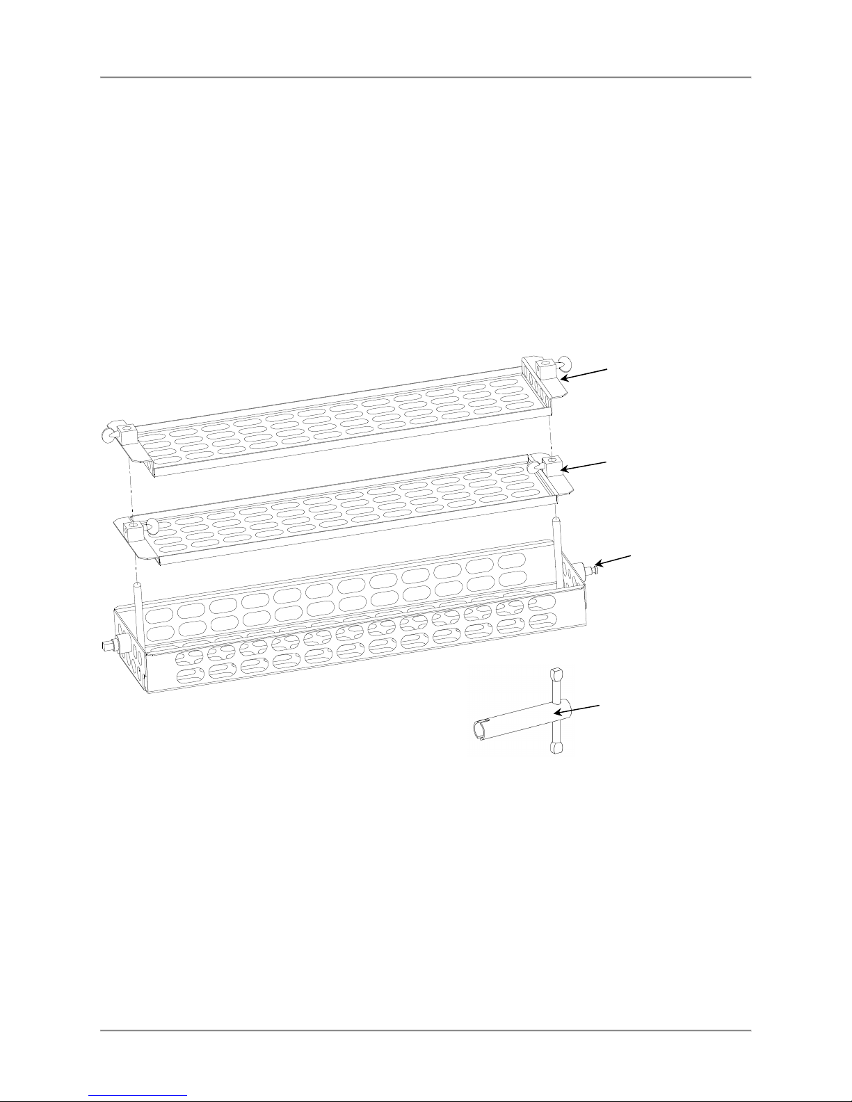
Rotisserie Oven Operation
Thumb Screw Wrench
Baskets
The optional tiered clamping baskets can be used to cook a wide variety meat portions and proteins. By
using the intermediate trays two layers of smaller portions can be cooked in a single basket. Note that
these baskets will not produce an even browning on the exterior of the cooked products.
Place the portions to be cooked in the Lower Tray of the baskets. The portions should be evenly
distributed in the Lower Tray with some space between each portion for adequate heat circulation.
Slide the Upper Tray over the vertical pins in the Lower Tray. Push the Upper Tray down onto the
portions to be cooked firmly enough that the portions do not move in the basket. Tighten the thumb
screws securely on each end with the thumb screw wrench. For larger portions, the Intermediate Tray
can be used in place of the Upper Tray.
To cook two layers of portions in the basket, load the first layer in the Lower Tray and secure this layer
with the Intermediate Tray as described above. In similar fashion place the second layer of portions in
the Intermediate Tray and secure this layer with the Upper Tray.
Load the baskets onto the ovens rotor system as described above for the V-spits.
Upper Tray
Intermediate Tray
Lower Tray
(FA55313800)
17
Page 20

Rotisserie Oven Installation
Installation
Serious injury, equipment damage or death could result if attempting to install this
oven yourself. Ensure that an authorized BKI service agent installs the oven.
Unpacking and Handling
It is the owners’ responsibility to file all freight claims with the delivering truck line. Inspect all cartons and
crates for damage as soon as they arrive. If damage to cartons or crates is found, or if a shortage is
found, note this on the bill of lading (all copies) prior to signing.
If damage is found when the equipment is opened, immediately call the delivering truck line and follow up
the call with a written report indicating concealed damage to your shipment. Ask for an immediate
inspection of your concealed damage item. Packaging material MUST be retained to show the inspector
from the truck line.
Remove all packing from the interior and exterior of the oven.
Location and Clearance
Install your oven in a well-ventilated area. This will ensure that the gas burns properly and will help
prevent any fires.
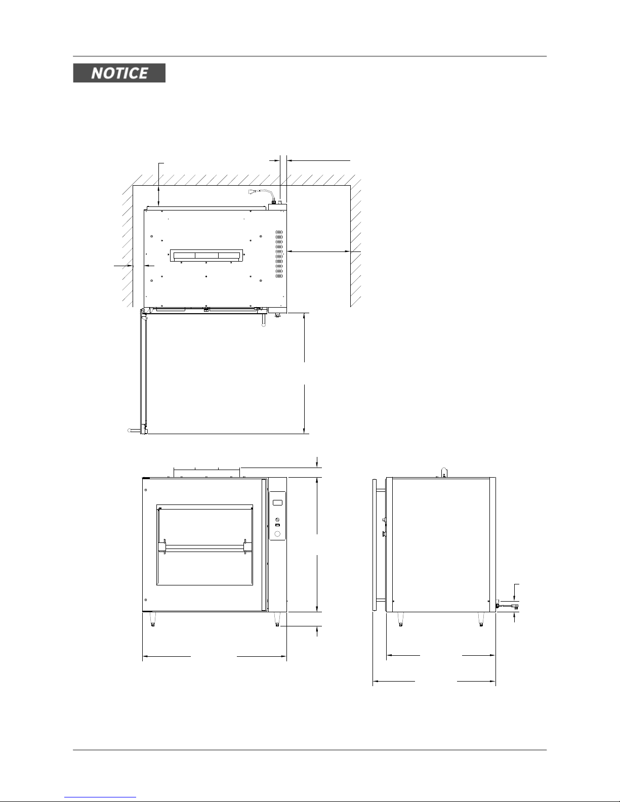
The oven must be mounted on a level surface capable of supporting the fully loaded oven. Refer to Chart
1 for oven weight.
Adequate clearance must be provided around the oven for safety, proper operation and ventilation. Refer
to
Chart 1 for required minimum clearances. Note that these are minimum clearances. If the oven is to be
permanently mounted near other immovable objects additional clearance must be provided for connection
and service of the oven on both sides.
All ventilation slots must be kept free from obstruction. The area around oven must be kept free and clear
from combustibles.
Specific Instructions
The oven must be installed under a ventilation hood. If the oven is not properly
ventilated, carbon monoxide can be released around the oven. Asphyxiation or
suffocation can occur if gas is not ventilated properly.
Installation of this appliance must conform with local codes, or in the absence of
local codes, with the National Fuel Gas Code ANSI Z223.11/NFPA 54 or Natural
Gas and Propane Code CSA B149.1 as applicable.
• This appliance and its individual shutoff valve must be disconnected from
• The appliance must be isolated from the gas supply piping system by
When installed, this appliance must be electrically grounded in accordance with
local codes, or in the absence of local codes, the National Electric Code
ANSI/NFPA 70 or the Canadian Electrical Code CSA C22.2, as applicable.
A wiring diagram is located on the inside of the appliance’s right side panel.
This appliance is equipped with a 3-prong (grounding) plug for your protection
against shock hazard and should be plugged directly into a properly grounded 3prong receptacle. Do not cut or remove the grounding prong from the plug.
the gas supply piping system during any pressure testing of that system
at test pressures in excess of ½ psi (3.5kPa).
closing its individual shutoff valve during any pressure testing of the gas
supply piping system at test pressures equal to or less than ½ psi
(3.5kPa).
18
Page 21
Rotisserie Oven Installation
When this appliance is installed with casters, it must be installed with the casters
supplied, a connector complying with either ANSI Z21.69 • CSA 6.16 and a quickdisconnect device complying with ANSI Z21.41 • CSA 6.9. It must also be
installed with restraining means to guard against transmission of strain to the
connector, such as BKI part number FT0279.
Chart 1. Location and Clearance
> 6in
[152.4mm]
1 7/8in
[47.6mm]
Counter Top and Stand
> 18in
> 3in
[76.2mm]
34 1/16in
[865.0mm]
2 11/16in
[67.9mm]
[457.2mm]
for SERVICE
ACCESS
TECHNICAL SPECIFICATIONS:
Net Weight: 450 lbs [204 kg]
Floor Space: 13.2 sq ft [1.2 sq m]
Voltage: 115V
Phase: 1
Frequency: 60 Hz
Amperage: 4.5A
Electrical Power: 540W
Electrical Plug: NEMA 5-15P
Gas Power: 75,000 BTU Max.
Gas Types: Natural & Propane
Min. Gas Pressure: 5 inch W.C.
Max. Gas Pressure:14 inch W.C.
Gas Inlet: 3/4" NPTM
FOR PROPER OPERATION
Use a minimum 3/4" pipe and
3/4" ID flexible gas connector
for gas supply connection.
∼
40 11/16in
[1033.7mm]
38in
[964.8mm]
4in
[101.6mm]
Model DRGV-7 Gas Rotisserie Oven
19
3in
[76.2mm]
30 3/4in
[781.0mm]
34 5/8in
[879.1mm]
Page 22

Rotisserie Oven Installation
> 3in
[76.2mm]
> 6in
[152.4mm]
1 7/8in
[47.6mm]
34 1/16in
[865.0mm]
> 3in
[76.2mm]
2 5/8in
[66.6mm]
TECHNICAL SPECIFICATIONS:
Net Weight: 900 lbs [408 kg]
Floor Space: 13.9 sq ft [1.3 sq m]
(2) Ovens Connect Independently
Specifications for Single Oven
Voltage: 115V
Phase: 1
∼
Frequency: 60 Hz
Amperage: 4.5A
Electrical Power: 540W
Electrical Plug: NEMA 5-15P
Gas Power: 75,000 BTU Max.
Gas Types: Natural & Propane
Min. Gas Pressure: 5 inch W.C.
Max. Gas Pressure:14 inch W.C.
Gas Inlet: 3/4" NPTM
FOR PROPER OPERATION
Use a minimum 3/4" pipe and
3/4" ID flexible gas connector
for gas supply connection.
32 15/16in
[836.6mm]
FLUE DUCTS ARE
REMOVABLE TO
ALLOW FOR
INSTALLATION
UNDER A HOOD
BUT MUST BE
REATTACHED
AFTER
INSTALLATION
DRAIN
VALVE
40 11/16in
[1033.7mm]
79 3/4in
[2025.4mm]
2 5/8in
[66.7mm]
1 5/8in
[41.6mm]
Model DRGV-14 Gas Rotisserie Oven
20
30 3/4in
[781.0mm]
34 5/8in
[879.1mm]
43 1/16in
[1093.5mm]
3in
[76.2mm]
Page 23
Rotisserie Oven Installation
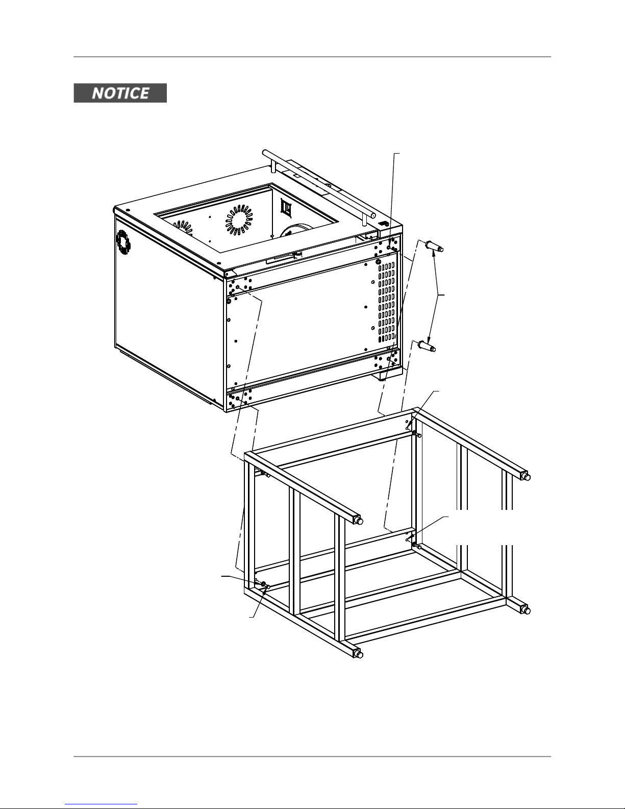
Mounting
This appliance cannot be mounted directly on a counter top. Air must be able to
circulate under the appliance. To prevent equipment damage the appliance must
be mounted on legs, casters or a stand with an open appliance mounting surface.
Screw Legs or Stand
mounting screws into
larger 3/8"-16 Thread
Inserts on each corner
of the oven base.
L0154 4 in.
Adjustable
Leg - (4) req'd.
(4) WSH046
3/8" Lock
Washer
(4) SCR068
3/8"-16 x 3/4"
Hex Head Screw
Use inner Stand
Mounting holes
in front of oven.
Use outer Stand
Mounting holes
in front of oven.
21
Page 24
Rotisserie Oven Installation
Stacking Ovens
Serious injury, equipment damage or death could result if attempting to install
these ovens yourself. Special equipment is required to lift and stack two ovens.
Ensure that an authorized BKI service agent installs the oven.
A DRGV-14 two cavity oven is shipped from the factory as two individual ovens along with the
components required to assemble them into a single unit. The lower oven will have casters installed, the
upper oven will not.
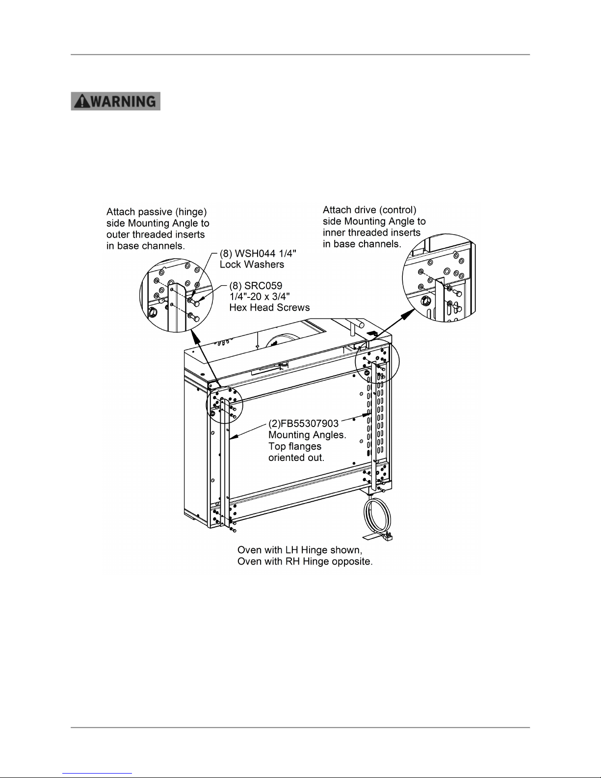
Prepare the top oven by attaching the mounting angle to the bottom as illustrated below.
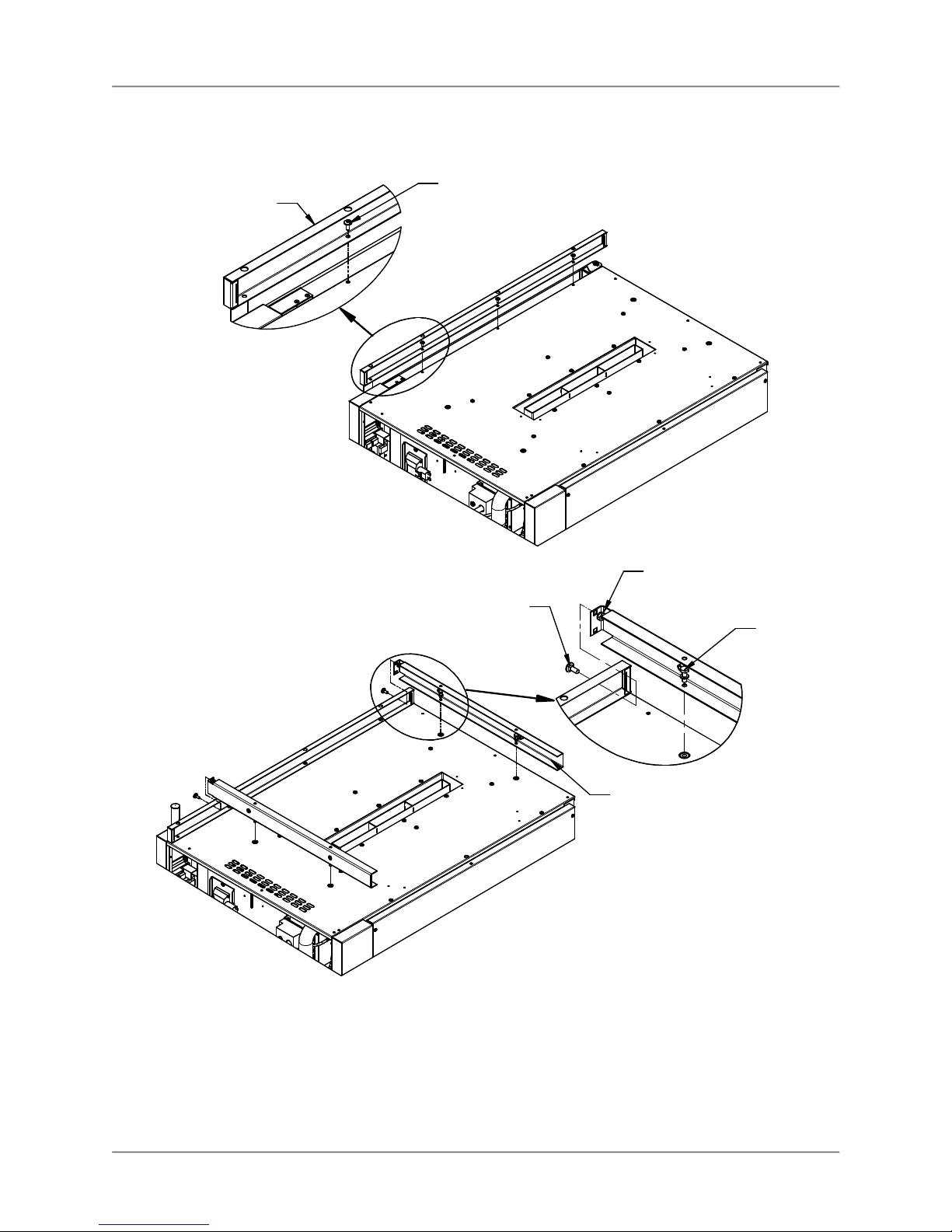
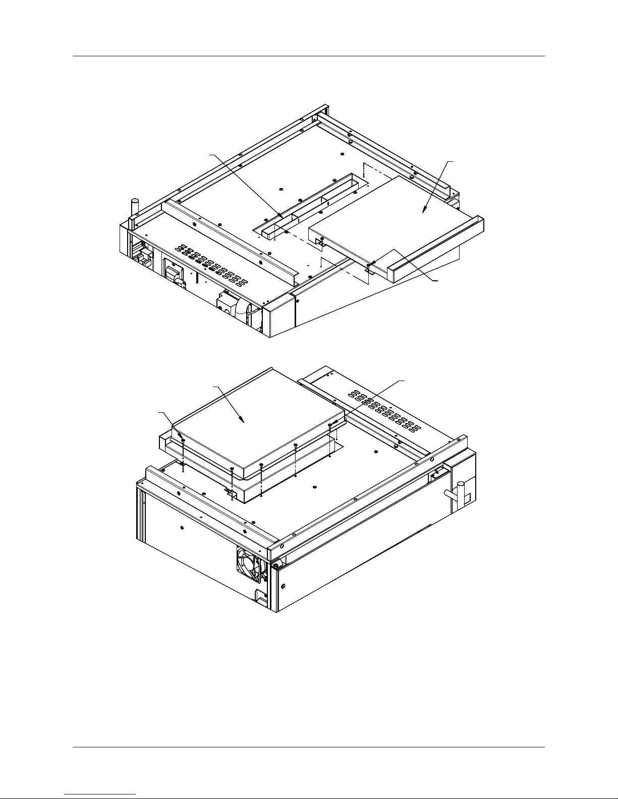
Prepare the lower oven by first removing the two side panels. Then attach the stacking channels, flue
duct and baffle as detailed in the following illustrations.
22
Page 25
Rotisserie Oven Installation
FB55308003
Front Trim orient as
shown.
ATTACH STACKING CHANNELS
Remove front (3) Top Panel mounting
Screws. Position Front Trim over mounting
holes and secure with Screws.
ATTACH FRONT TRIM
(2) WSH248
1/4"-20 Keps
(2) BLT257
Nuts
1/4"-20 x 5/8"
Carriage Bolts
(2) FB55307803 Channels
(with factory installed
thread inserts)
(4) SCR059
1/4"-20 x 3/4"
Hex Screws
&
(4) WSH044
1/4" Lock
Washers
23
Page 26
Rotisserie Oven Installation
Flue Ducts slides over the
outside of the Oven Flue
WB55306700
Flue Duct
(4) SCR138
#10 x 1/2"
Screws
ATTACH FLUE DUCT
(4) SCR138
#10 x 1/2"
Screws
FB55308203
Flue Baffle
Remove existing (3)
Screws, position Flue
Baffle & re-install Screws.
ATTACH FLUE BAFFLE
Lift the top oven and set it in place on the lower oven as shown in the following illustration. Ensure the
lifting equipment has a rated capacity of at least 500 lb. [250 kg].
The angles on the bottom of the top oven slide over the outside of the channels attached to the top of the
lower oven.
24
Page 27

Rotisserie Oven Installation
Secure the two ovens to each other with the fasteners noted on the illustration.
(4) 1/4"-20 Threaded Inserts in
top may be used to attach lifting
hardware. Minimum capacity
of lifting hardware is 500 lb. [250 kg].
(4) SCR059 1/4"-20 x 3/4"
Hex Head Screws &
(4) WSH2661/4" Flat
Washer &
(4) WSH044 1/4" Lock
Washer
25
Page 28

Rotisserie Oven Installation
Attach Lower and Upper Oven Flue Chimneys and Side Trims as illustrated below.
Lower Oven
Flue Chimney
Assembly
Upper Oven
Flue Chimney
(4) SCR138
#10 x 1/2" Screws
install in top two
holes in ends of
Flue Chimey
Tab on front
flange of Side
Trim fits into
slot in end of
Front Trim
(4) SCR138
#10 x 1/2"
Screws
(4) SCR138
#10 x 1/2" Screws
installed thru Top
Panel of lower
oven into Side Trim
(2) FB55308103
Side Trim - fit between
top panel of lower oven
and base plate of
upper oven
Lower oven Flue Duct
slides inside of Chimney
It will be necessary
to remove the cooling
fan on this side of the
lower oven to install
the Side Trim screw.
Re-install cooling fan
after installing Side
Trim.
26
Page 29
Rotisserie Oven Installation
Locking Ovens in Place
For ovens equipped with casters, injury or equipment damage could result if the
ovens are not locked in position to prevent movement during normal operation.
Locking casters are provided on ovens with 3” diameter and larger casters. To prevent movement of the
ovens once they are in their installed position depress the caster locking lever on the side of the two front
casters with your foot.
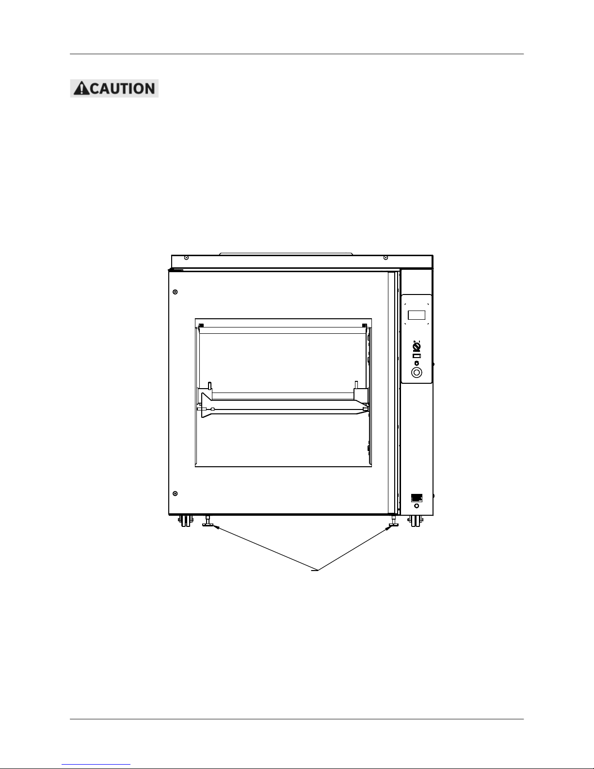
Low profile ovens with 2” diameter casters are provided with two legs in the front of the base of the lower
oven. Once the ovens are moved to their installed position, lower these legs to firmly contact the floor,
preventing movement of the ovens.
LEG LEVELERS TO BE LOWERED
TO CONTACT FLOOR TO PREVENT
MOVEMENT WHEN OVEN IN
OPERATING POSITION.
DRGV-14 LOWER OVEN with 2" CASTERS
27
Page 30

Rotisserie Oven Installation
Gas Supply Connection
Installation of this appliance must conform with local codes or in the absence of
local codes with the National Fuel Gas Code ANSI Z223.11/NFPA 54 or Natural
Gas and Propane Code CSA B149.1 as applicable.
The gas supply connection for the oven is located on the
back of the oven as shown. A separate gas supply must
be provided for each oven cavity for stacked ovens
(DRGV-14).
A 3/4” NPT nipple is provided for the gas supply
connection. For proper oven operation the gas supply
piping and connector must have a minimum capacity of
80,000 BTU per Hr. If a flexible connector with quick
disconnect device is utilized, a minimum 3/4” ID flexible
connector and quick disconnect devise must be used.
Gas Supply
Connection
(3/4” NPT)
Gas Manifold Pressure Test
The gas manifold pressure is preset at the factory. Due
to variations in gas supply pressures, the manifold
pressure should be checked after installation of the oven.
Refer to the oven’s rating plate for the required manifold
pressure setting. Typically the manifold pressure will be
4 1/2 inches of water column for natural gas and 7 inches
of water column for lp gas.
To check the manifold pressure connect a manometer to
the OUTLET PRESSURE TAP (see diagram at right).
Connect the oven’s gas supply and electric cord, turn the
oven on and start a cook program so that the oven
burner lights. With the burner lit compare the manifold
pressure on the manometer to the rated manifold pressure.
If the actual manifold pressure is different than the rated pressure use the PRESSURE REGULATOR
ADJUSTMENT on the valve to correct the manifold pressure. It will be necessary to remove the CAP
SCREW to access the PRESSURE REGULATOR ADJUSTMENT (see diagram at above).
Be sure to disconnect the manometer and reinstall the plug in the valve’s OUTLET PRESSURE TAP after
the competition of gas manifold pressure test.
COMBINATION GAS VALVE
28
Page 31
Rotisserie Oven Maintenance
Frequency
Performed By
Part Activity
Maintenance
The restraining device must always be connected when the appliance is in
service. Disconnect for movement, such as servicing or cleaning. Reconnect the
restraining device after appliance has been returned to its normal position.
Failure to comply with the maintenance below could result in a serious accident or
equipment damage.
Failure to remove power from this unit before performing maintenance may cause
severe electrical shock. This unit may have more than one disconnect switch.
Scheduled Maintenance
Use the following table to help manage scheduled maintenance activities.
Daily User Entire Oven Perform oven-cleaning procedure.
Daily User Drive Rotor
Gears
6 months User Fan Blade Remove and replace.
Cleaning is not only necessary for sanitary reasons, but will increase sales appeal and maximize
operating efficiency.
Lubricate planetary gear teeth.
Failure to remove power from this unit may cause severe electrical shock. This
unit may have more than one disconnect switch.
Always wear appropriate personal protection equipment (googles, rubber glove &
long sleeved garments) when cleaning the oven to guard against possible injury.
Using abrasive cleaners will damage the cabinet finish. Use only a mild soap and
water solution or approved cleaner.
DO NOT USE OVEN CLEANER on this machine. Caustic cleaners will cause
damage to the machine.
NEVER USE A WATER HOSE OR A STEAM CLEANER TO WASH THIS UNIT.
Excess water can get into the interior of the cabinet and cause damage.
BKI Approved Cleaning Solutions
ECOLAB Greasestrip Plus
Proctor & Gamble DCT Oven Cleaner
J. Wilson Marketing Combi Brite Cleaner
Daily Cleaning & Maintenance
1. Allow oven to cool below 50o C-55o C (120o F-130o F).
2. Turn the Main Power Switch off and unplug the appliance.
3. Empty the Dripping Drawer using the drain valve or fat pump (refer to Figure 1 below).
4. Remove all food products from the unit.
5. Remove V-spits, or Baskets from the unit and place them in a large sink to soak in hot cleaning
solution. Clean the components with warm water, a sponge and BKI Cleaner. Wipe dry with a
clean cloth.
29
Page 32

Rotisserie Oven Maintenance
STEP 1
STEP
2
STEP
3
oven by pulling out on the outside of
6. Remove the Rotor System as described below:
Turn Rotor Shaft Nuts on both ends
of shaft counter clockwise until the
threads on the Nut disengage the
threads on the Rotor Hub. Slide
Nuts toward the center of the shaft.
Grasp the Rotor Shaft with both
hands and lift the shaft out of the
Rotor Hub saddles and remove it
from the oven.
Remove the Rotor Disks from the
the disks while rotating them back
and forth.
7. Place the Rotor System components in a large sink to soak in hot cleaning solution. Clean the
components with warm water, a sponge and BKI Cleaner. Wipe dry with a clean cloth.
8. Remove the Fan Guard by pulling it straight out of the top of the oven cavity (refer to Figure 1
below).
Fan Blades under
Fan Guard
Tabs on Fan Guard insert
into these slots.
Fan Guard
sits on pin,
both sides
Fan Guard - pull
straight out to remove,
reinstall as shown.
Dripping Drawer
Figure 1
30
Burner Cover - lift
up to cover Burner
during cleaning.
Wire Rack or Drip Tray
sits on pins in the front
& back of the cavity
Page 33
Rotisserie Oven Maintenance
STEP 1
engage the gears and the drive hub.
side.
STEP
2
Shaft ends must insert into the holes
STEP
3
ends of the shaft over the Rotor Disk
9. Remove the Wire Racks or Drip Tray and the Dripping Drawer from the oven (refer to Figure 1
above).
10. Clean the Fan Guard, Wire Racks or Drip Tray and Dripping Drawer with mild soap and water
solution or approved cleaner and a sponge. Wipe dry with a clean cloth.
11. Clean in interior oven cavity with mild soap and water solution or approved cleaner and a sponge.
Wipe dry with a clean cloth.
12. Carefully clean the fan blades using a mild soap and water solution or approved cleaner and a
scrub brush. Do not bend or disfigure the fan blades.
13. Clean the outside of the oven with mild soap and water solution or approved cleaner and a
sponge. Wipe dry with a clean cloth.
14. Replace the Fan Guard, Wire Racks or Drip Tray and Dripping Drawer in the oven cavity (refer to
Figure 1 above).
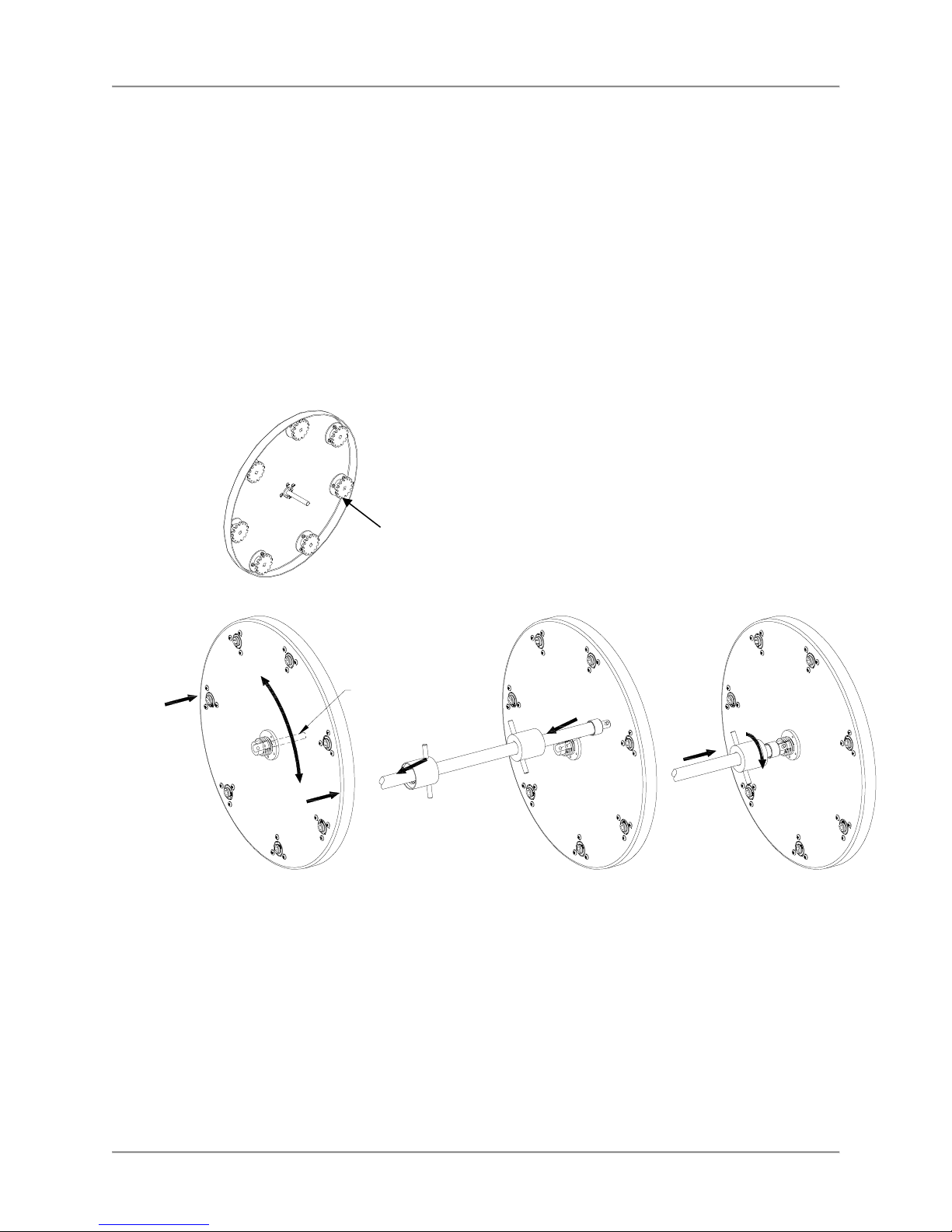
15. Lubricate the gears on the Drive Rotor as shown below with Permatex® Super Lube® Synthetic
Lubricant with PTFE (BKI part number L0200).
Lubricate gear teeth.
16. Reinstall Rotor System as shown below.
Install the Rotor Disks by first
inserting the guide pin into the shaft
center hole. The Rotor Disk with
gears goes on the right side of the
oven. It will be necessary to rotate
this Rotor Disk while pushing in to
ROTOR
GUIDE
PIN
Rotate both Rotor Disks so that the
U-shaped slot in the hubs is facing
up and forward as shown. Grasp
the Rotor Shaft with both hands and
insert the ends into the U-shaped
hub slots. The pins in the Rotor
Slide the Rotor Shaft Nuts on both
hub and tighten by rotating the nuts
clockwise.
When properly installed there will be
approximately ¼” [6 mm] space
between the Rotor Disk and cavity
in the bottom of the U-shaped slots
in the Rotor Disk Hubs.
31
Page 34

Rotisserie Oven Maintenance
Problem
Cause
Possible Solution
Troubleshooting
Unit will not turn on. Main Power
Isolator Light is not illuminated.
Problem with building power supply Check circuit breaker at building
Unit will not turn on. Main Power
Isolator Light is illuminated.
Defective Power Switch. Contact BKI service agent for
Rotor not rotating with door
closed.
Defective door switch. Contact BKI service agent for
Defective relay. Contact BKI service agent for
Defective motor or capacitor. Contact BKI service agent for
Rotor will not rotate while
depressing Rotor Jog Switch with
door open but operates with door
closed.
Oven does not heat at all. Improper program settings. Check program settings.
Improper parameter settings. Contact BKI service agent for
Defective cooking controller. Contact BKI service agent for
Defective gas valve or spark
Defective combustion blower or
Problem with building gas supply. Contact local gas company
Burner ignites but then quickly
extinguishes.
Control displays “999” under the
temperature display.
“Call for Service” light on lower
control panel illuminated
Cavity lights do not illuminate
when unit is on.
Individual cavity lamp does not
illuminate.
Unit power plug disconnected. Plug unit into mating receptacle.
power panel. If problem persists,
contact BKI service agent for
corrective action.
Safety cut out thermostat tripped or
defective.
Door not completely closed. Check that both doors are
Defective Rotor Jog Switch. Contact BKI service agent for
module.
pressure switch.
Fouled flame sense probe. Contact BKI service agent for
Temperature probe connection
loose or defective probe.
Cooling fan or pressure switch
malfunctioning.
Blown fuse. Contact BKI service agent for
Defective bulb. Contact BKI service agent for
Contact BKI service agent for
corrective action.
corrective action.
completely closed
corrective action.
corrective action.
corrective action.
corrective action.
corrective action.
corrective action.
Contact BKI service agent for
corrective action.
Contact BKI service agent for
corrective action.
service representative.
corrective action.
Contact BKI service agent for
corrective action.
Contact BKI service agent for
corrective action.
corrective action.
corrective action.
32
Page 35

Rotisserie Oven Accessories
G0089 HI
-
TEMP GLOVES
Accessories
L0200 PTFE
LUBRICANT
MF0047 V-SPIT
AB55310000 TIERED BASKET
AB55315500 12 ROD SPIT RACK
(capacity- 60 V-Spits & 9 Baskets)
AB55317400 6 ROD RACK
CHANNEL
(order Rods separately)
FA55313800 THUMB
SCREW WRENCH
WA55315300 V-Spit Rod
WA55315400 Basket Rod
WA55314200
SPIT HOLDER
requires Ø1 1/2”
mounting hole.
DRGV-7 STANDS
AN55310700 Open Stand, Adjustable Feet
AN55310800 2 Shelf Stand, Adjustable Feet
AN55316200 Open Stand, Swivel Casters
AN55316300 2 Shelf Stand, Swivel Casters
(2 Shelf Stand with Swivel Casters shown.)
33
Page 36

Rotisserie Oven Wiring Diagram
Wiring Diagram
FN5
P1
CP1
FN4
LADDER DIAGRAM
CS1
SW1
L1
SW4
L1
L2
L1
SW1
3
2
TC1
1
FN4
FN6
L3
1
1
CP1
2
1
1
SW2
FN5
2
4
FN3
FN2
FN1
2
2
2
2
2
L3
SW4
5
5
2
TB1
TF1
R1
R2
SW3
R1
8
SW4
8
1
1
1
1
1
(8A)
7
13
SM1
R1
6
9
6
11
11
10
12
11
V1
12
2
12
11
2
2
L2
2
CP 1- CP 004 6 CON TRO L, TOU CH SCR EEN
Con sul t Fa ct ory for cu sto mer spe cif ic
pre -pro gra mme d c ont rol .
P1 - T00 07 PR OBE , TE MPE RAT URE
CS 1-E B68 692 800 CO RDS ET, 90" NE MA 5-1 5
F040 6 C ORD RE STR AIN T
F1 - F039 4 FUS E, 8A
F U00 4UK FU SE H OLD ER
FN 1- F N00 55 FAN CO MPL ETE , CC W, 115 V
FN00 48 FAN BL ADE , C CW
F N00 49 NUT , CC W F AN BLA DE
FN 2- F N00 56 FAN CO MPL ETE , CW , 1 15V
FN00 51 FAN BL ADE , C W
F N00 52 NUT , FA N B LAD E, CW
FN 3- F N00 54 FAN , C OMB USTI ON
FN 4- F N00 46 FAN , C OOL ING, 11 5V
FN 5- F N00 46 FAN , C OOL ING, 11 5V
FN 6- F N00 46 FAN , C OOL ING, 11 5V
L 1- L I01 6UK CL R P ILO T L IGH T, 2 50V
L 2- L H00 34 LAM P H OLD ER, 115 V
B05 68 BUL B, 40W , 11 5V
7
9
SW2
SW3
F1
L2
FN2
FN1
TC1
(8A)
F1
L2
L 3- PL0 004 PIL OT LIG HT
M 1- M0 115 GE ARM OTOR , 1 15V
R 1- R 019 1 R ELA Y, SPD T, 20A , 11 5V
R 2- R 019 1 R ELA Y, SPD T, 20A , 11 5V
SM 1- C07 69 SPA RK MOD ULE
MB 441 154 00 IGN ITIO N P ROB E
SW 1-S 030 4 P B O PER ATO R, 2 PO S.
S 030 7 C ONT ACT BL OCK ,
SW 2-S 030 9 P B O PER ATO R, M OME NTA RY
S0 307 CO NTA CT BLO CK, 1 N .O.
SW 3-S 036 6 P LUN GER SW ITCH , S PDT
SW 4-S 017 4 S WIT CH, VAC UUM
SW 5-S 017 4 S WIT CH, VAC UUM
TB 1- T B00 65 TER MIN AL SEC TION , 2 CO ND
TB 006 7 TER MIN AL S ECT ION , 4 CO ND
TB 006 9 TER MIN AL E ND PLA TE
TC 1- T 010 8TH ERM OST AT, MA N RE SET
TF 1- E A55 390 100 TR ANSF ORM ER 120 V/2 4V
V 1- C0 739 GA S V ALV E
WIRES PASSING
UNDER BASE
SM1
SW5
V1
FN6
WHT
BLK
M1
RED
FN3
CS1
34
Page 37

Rotisserie Oven Notes
Notes
35
Page 38

2812 Grandview Drive, Simpsonville, S.C. 29680, USA
http://www.bkideas.com
Made and printed in the U.S.A.
SS-OM-051.02 9/02/15
 Loading...