

Page 1
Automatic Lift Fryer
MODELS BLF-F, & BLF-FC
Service Manual
Serial Numbers 121836 and higher
Page 2

Warranty Information
LIMITED ONE YEAR WARRANTY
BKI (The “Company”) warrants to the original purchaser/user, that at time of shipment from the Company
factory, this equipment will be free from defect in materials and workmanship. Written notice of a claim
under this Warranty must be given within ONE YEAR AND THREE MONTHS from date of shipment from
the factory. Defective conditions caused by abnormal use or misuse, lack of maintenance, damage by
third parties, alterations by unauthorized personnel, acts of God, failure to follow installation instructions
or any other events beyond the control of the company will NOT be covered under Warranty. The
obligation of the Company under this Warranty shall be limited to repairing or replacing (at the option of
the company) any part which is defective in reasonable opinion of the Company. The user will have the
responsibility and expense of removing and returning the defective part to the Company as well as the
cost of reinstalling the replacement or repaired part.
IN NO EVENT SHALL THE COMPANY BE LIABLE FOR LOSS OF USE, LOSS OF REVENUE OR
LOSS OF PRODUCT OR PROFIT OR FOR INDIRECT OR CONSEQUENTIAL DAM AGES INCLUDING
BUT NOT LIMITED TO, FOOD SPOILAGE OR PRODUCT LOSS. WARRANTY DOES NOT COVER
GLASS BREAKAGE. THE ABOVE WARRANTY IS EXCLUSIVE AND ALL OTHER WARRANTIES,
EXPRESS OR IMPLIED, ARE EXCLUDED INCLUDING THE IMPLIED WARRANTIES OF
MERCHANTABILITY AND FITNESS FOR A PARTICULAR PURPOSE. THIS WARRANTY SHALL
APPLY ONLY WITHIN THE CONTINENTAL UNITED STATES, ITS TERRITORIES, AND
POSSESSIONS AND IN CANADA.
LIMITED NINETY DAY LABOR WARRANTY
All labor necessary to repair or replace factory defective parts will be performed, without charge, to the
end user, by service personnel of a BKI Authorized Distributor during the first ninety days after the date of
installation of the new equipment.
Replacement parts: Any appliance replacement part, except lamps and fuses, which proves to be
defective in material or workmanship within 90 days from date of original installation will be repaired or
replaced without charge F.O.B. Factory, Simpsonville, S.C. or F.O.B. authorized distributor.
Page 3

Automatic Lift Fryer Table of Contents
Table of Contents
Table of Contents........................................................................................................................................1
Introduction .................................................................................................................................................2
Safety Precautions....................................................................................................................................2
Safety Signs and Messages.................................................................................................................2
Safe Work Practices.............................................................................................................................3
Safety Labels........................................................................................................................................7
Installation ...................................................................................................................................................8
Unpacking and Handling...........................................................................................................................8
Assembly and Mounting ...........................................................................................................................8
Wiring........................................................................................................................................................8
Initial Test and Adjustment .......................................................................................................................9
Replacement Parts....................................................................................................................................10
Assemblies..............................................................................................................................................10
Accessories.............................................................................................................................................23
Components............................................................................................................................................25
Wiring Diagrams........................................................................................................................................27
Notes ..........................................................................................................................................................44
1
Page 4
Automatic Lift Fryer Introduction
Introduction
The BLF Fryer is compact, attractive and functional in design. It is constructed of a stainless steel fryer
pot for cleaning ease. Exclusive BKI patented features and safety devices offer flexibility, efficiency and
reliability plus PERFECTION IN FRYING!
The BKI name and trademark on this unit assures you of the finest in design and engineering -- that it has
been built with care and dedication -- using the best materials available. Attention to the operating
instructions regarding proper installation, operation, and maintenance will result in long lasting
dependability to insure the highest profitable return on your investment.
PLEASE READ THIS ENTIRE MANUAL BEFORE OPERATING THE UNIT. If
you have any questions, please contact your BKI Distributor. If they are unable to
answer your questions, contact the BKI Technical Service Department, toll free:
1-800-927-6887. Outside the U.S., call 1-864-963-3471.
Safety Precautions
Always follow recommended safety precautions listed in this manual. Below is the safety alert symbol.
When you see this symbol on your equipment, be alert to the potential for personal injury or property
damage.
Safety Signs and Messages
The following Safety signs and messages are placed in this manual to provide instructions and identify
specific areas where potential hazards exist and special precautions should be taken. Know a nd
understand the meaning of these instructions, signs, and messages . Damage to the equipment, death or
serious injury to you or other persons may result if these messages are not followed.
This message indicates an imminently hazardous situation which, if not avoided,
will result in death or serious injury.
This message indicates a potentially hazardous situation, which, if not avoided,
could result in death or serious injury.
This message indicates a potentially hazardous situation, which, if not avoided,
may result in minor or moderate injury. It may also be used to alert against
unsafe practices.
This message is used when special information, instructions or identification are
required relating to procedures, equipment, tools, capacities and other spe cial
data.
2
Page 5
Automatic Lift Fryer Introduction
Safe Work Practices
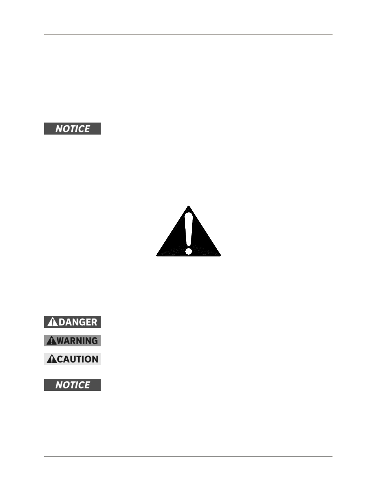
Keep The Casters Locked
To avoid spilling shortening, keep the casters locked. If any
shortening spills near your fryer, clean it up immediately.
Noncombustible Floors Only
Make sure your floor is noncombustible. Do not operate your fryer
on floors that are wood, carpeted or have rubber mats.
• Placing your fryer on a combustible floor could cause a fire.
Serious injury could result.
• Examples of noncombustible floors where you can safely
place your fryer are concrete, tile, and ceramic.
Keep The Area Around Your Fryer
Uncluttered
Make sure to keep the area around your fryer clear of any
obstacles.
Serious injury can occur if you trip or fall near the fryer. You could
be burned by hot shortening that splashes out of the fryer or by
falling against the hot metal of the fryer.
Keep The Floor Around Your Fryer Clean Of
Shortening
Make sure to keep the floor around your fryer clean of shortening
and other liquids.
Serious injury can occur if you slip near your fryer. You could be
burned by hot shortening that splashes out of the fryer or by falling
against the hot metal of the fryer.
3
Page 6
Automatic Lift Fryer Introduction
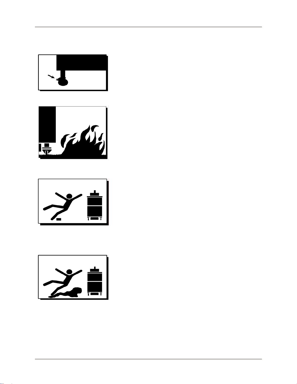
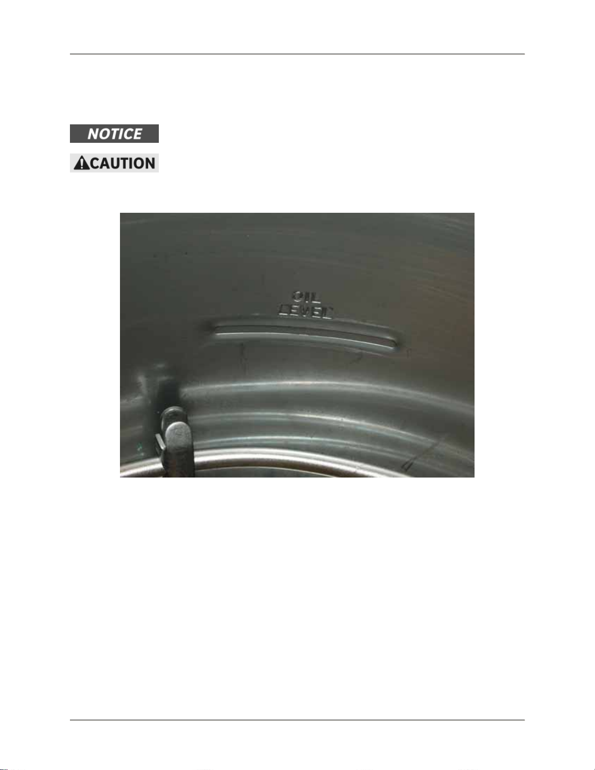
Do Not Overfill The Fryer With Shortening
Hot shortening and steam may escape and burn you if you put too
much shortening in the fryer. Fill the fryer to approximately one inch
below the fill marks that are inside the fryer pot. Heat the
shortening. If needed, carefully add more shortening to bring the
level to the fill marks.
Do Not Let Any Water Get Into The Fryer
Always remove excess moisture from food before placing it into the
fryer basket. Water will cause the hot shortening to spatter. You
could be burned.
Do Not Overload The Basket With Food
Hot shortening and steam may escape and burn you if you place
too much food in the basket.
Wear Safe Clothing Appropriate To Your Job
Always wear your insulated mitts when handling the fryer basket or
touch any hot metal surfaces. You received a pair of insulated mitts
with your fryer. If you lose or damage your mitts, you can buy new
ones at your local restaurant equipment supply store or from your
local BKI Distributor.
Always wear non-skid shoes when working around the fryer or any
other equipment that uses shortening. Never wear loose clothing
such as neckties or scarves while operating your fryer. Keep loose
hair tied back or in a hair net while operating your fryer.
Always wear appropriate personal protection equipment during the
filtering process to guard against possible injury from hot oil.
Always wear appropriate personal protection equipment during the
boil-out process to guard against possible injury from hot cleaning
solution.
4
Page 7
Automatic Lift Fryer Introduction
Keep this manual with the Equipment
This manual is an important part of your equipment. Always keep it
near for easy access.
If you need to replace this manual, contact:
BKI
Technical Services Department
P.O. Box 80400
Simpsonville, S.C. 29680-0400
Or call toll free: 1-800-927-6887
Outside the U.S., call 864-963-3471
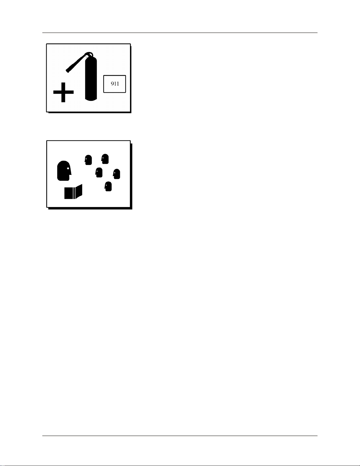
Protect Children
Keep children away from this equipment. Children may not
understand that this equipment is dangerous for them and others.
NEVER allow children to play near or operate your equipment.
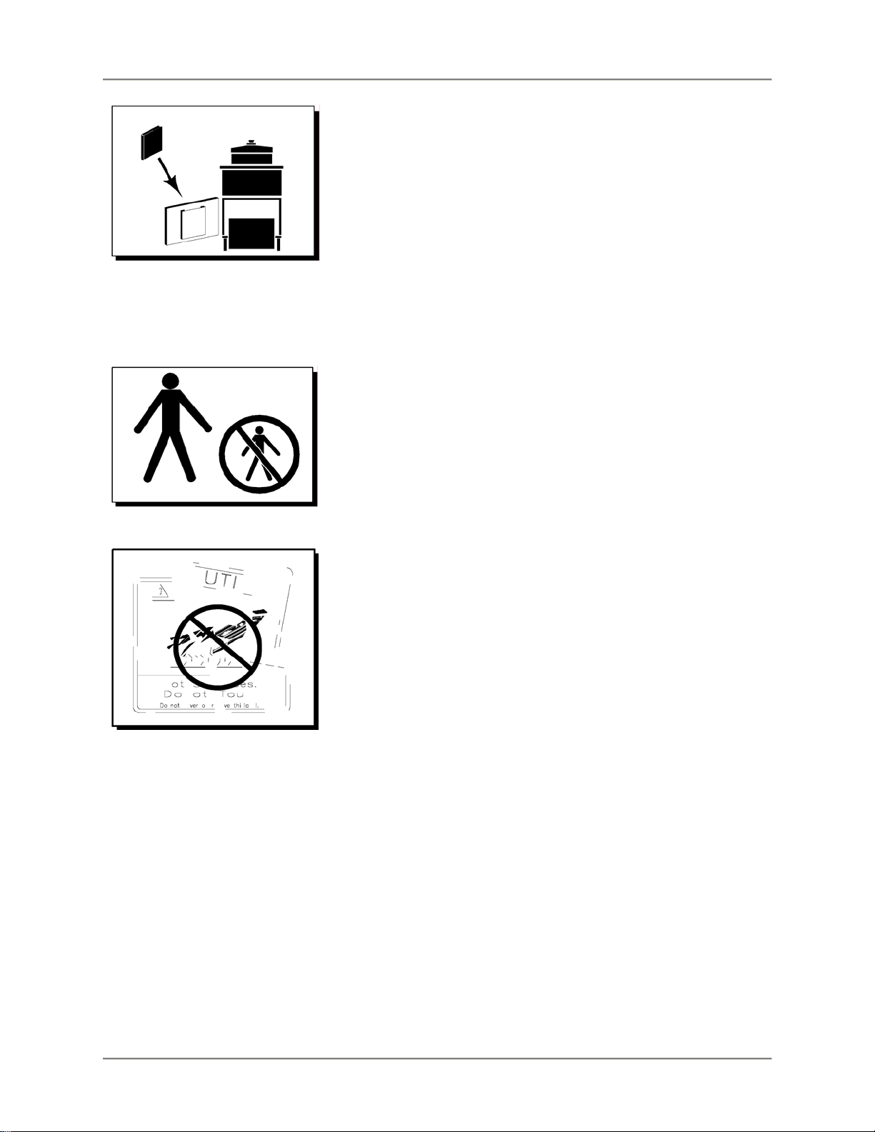
Keep Safety Labels Clean and in Good
Condition
Do not remove or cover any safety labels on your equipment. Keep
all safety labels clean and in good condition. Replace any damaged
or missing safety labels. Refer to the Safety Labels section for
illustration and location of safety labels on this unit.
If you need a new safety label, obtain the number of the specific
label illustrated on page 7, then contact:
BKI
Technical Services Department
P.O. Box 80400
Simpsonville, S.C. 29680-0400
Or call toll free: 1-800-927-6887
Outside the U.S., call 864-963-3471
5
Page 8
Automatic Lift Fryer Introduction
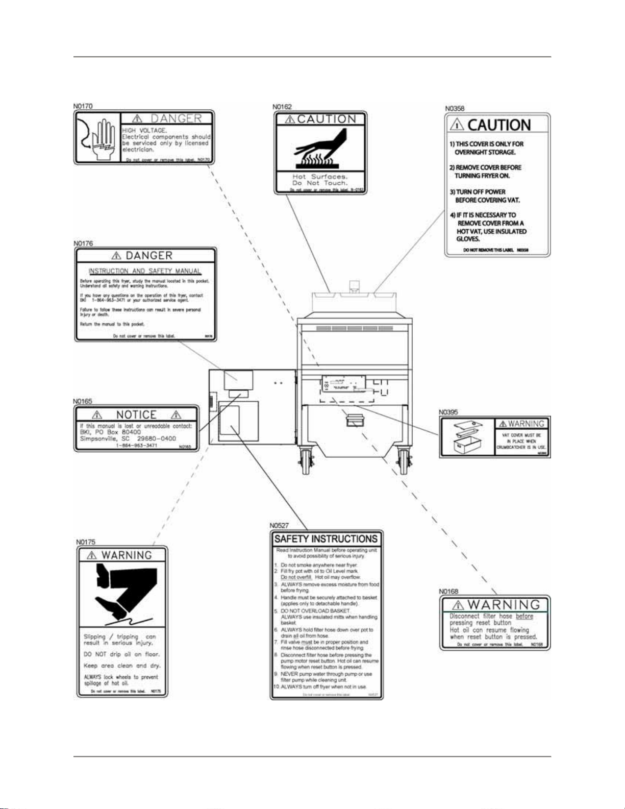
Be Prepared for Emergencies
Be prepared for fires, injuries, or other emergencies.
Keep a first aid kit and a fire extinguisher near the equipment. You
must use a 40-pound Type BC fire extinguisher and keep it within
25 feet of your equipment.
Keep emergency numbers for doctors, ambulance services,
hospitals, and the fire department near your telephone.
Know your responsibilities as an Employer
• Make certain your employees know how to operate the
equipment.
• Make certain your employees are aware of the safety
precautions on the equipment and in this manual.
• Make certain that you have thoroughly trained your employees
about operating the equipment safely.
• Make certain the equipment is in proper working condition. If you
make unauthorized modifications to the equipment, you will
reduce the function and safety of the equipment.
6
Page 9
Automatic Lift Fryer Introduction
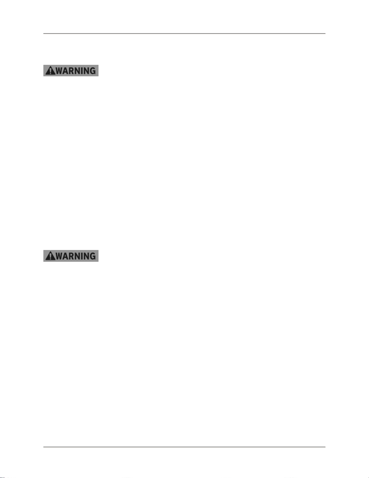
Safety Labels
7
Page 10
Automatic Lift Fryer Installation
Installation
Serious injury, equipment damage or death could result if attempting to install
this fryer yourself. Ensure that an authorized BKI service agent installs the fryer.
Unpacking and Handling
It is the owners’ responsibility to file all freight claims with the delivering truck line. Inspect all cartons and
crates for damage as soon as they arrive. If damage to cartons or crates is found, or if a shortage is
found, note this on the bill of lading (all copies) prior to signing.
If damage is found when the equipment is opened, immediately call the delivering truck line and follow up
the call with a written report indicating concealed damage to your shipment. Ask for an immediate
inspection of your concealed damage item. Packaging material MUST be retained to show the inspector
from the truck line.
Assembly and Mounting
1. Remove all packing materials from the interior and exterior of the fryer.
2. Lock the casters so the fryer does not move. Every time the fryer is used, make sure the casters
are locked so the fryer cannot move.
3. Clean the fryer pot before filling with shortening.
4. Place the DRAIN handle in the CLOSED position.
Wiring
Electrocution, equipment failure or property damage could result if an unlicensed
electrician performs the electrical installation. Ensure that a licensed electrician
perform the electrical installation in accordance with local codes, or in the absence
of local codes, with the National Electrical Code, ANSI NFPA 70-20XX.
This unit, when installed by an authorized BKI service agent, must be wired for use in accordance with all
applicable local, state, and federal codes. For specific electrical requirements and conne ction s refer to the
wiring diagram attached to the unit or provided in the Service Manual.
8
Page 11
Automatic Lift Fryer Installation
Initial Test and Adjustment
1. Fill pot with shortening to about one inch below the mark.
Use only high-quality shortening that has low moisture content, a high smoke
point and no additives.
Overfilling the fryer pot with shortening could lead to serious injury. Ensure that
the fryer pot is filled with shortening only to the fill mark when shortening is hot.
Do not use any shortening other than what is specified in this manual and do not
overfill the fryer pot.
2. Place the FILTER/OFF/FRY switch to the FRY position. The shortening should begin to heat and
begin to reach the fill mark inside the pot. Add more shortening as required to reach the fill mark.
Refer to the troubleshooting section if this does not occur.
9
Page 12
Automatic Lift Fryer Replacement Parts
Replacement Parts
Use the information in this section to identify replacement parts. To order replacement parts, call your
local BKI sales and service representative. Before calling, please note the serial number, model number
and voltage on the rating tag affixed to the unit.
Assemblies
Description Assembly # Figure # Table #
DOOR ASSEMBLY AB16006700 Figure 1 Table 1
DRAIN VALVE & PLUGS SB1999S Figure 2 Table 2
DRAIN/MOTOR/PIPING ASSEMBLY N/A Figure 3 Table 3
FRONT PANEL BLF-F EUROPE
FRONT PANEL BLF-F DOMESTIC
FRONT PANEL BLF-FC EUROPE
FRONT PANEL BLF-FC DOMESTIC
REAR PANEL BLF-F EUROPE
REAR PANEL BLF-F DOMESTIC
REAR PANEL BLF-FC EUROPE
REAR PANEL BLF-FC DOMESTIC
OIL VAT ASSEMBLY AN16010200 Figure 8 Table 8
QUICK DISCONNECT ASSEMBLY
TERM BLOCK ASSEMBLY ENGLAND AN19102100 Figure 10 Table 10
AN16017700
AN16017300
AN16017800
AN16017400
AN16017500
AN16017100
AN16017600
AN16017200
AN19103300
SB1997S
Figure 4 Table 4
Figure 5 Table 5
Figure 6 Table 6
Figure 7 Table 7
Figure 9 Table 9
10
Page 13
Automatic Lift Fryer Replacement Parts
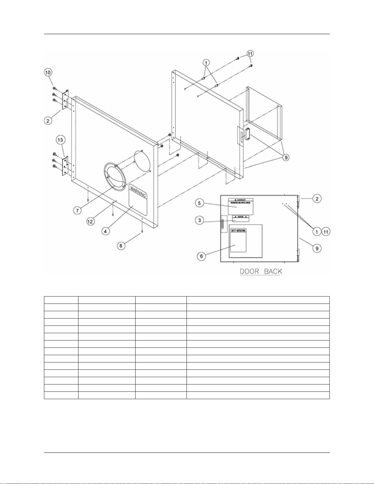
Figure 1. Door Assembly
Table 1. Door Assembly Parts
ITEM # PART # QTY DESCRIPTION
1 F0083 2 THREAD INSERT 10-24 STEEL
2 H0010 1 HINGE, LH PIN HALF
3 N0165 1 DECAL, NOTICE LOST MANUAL
4 N0175 1 DECAL, SLIPPING ADMONITIONS
5 N0176 1 DECAL, INSTR & SAFETY MANUAL
6 N0527 1 DECAL, SAFETY INSTR FRYERS
7 P0022 1 HANDLE, PULL SS P60-1010
8 RIV172 3 RIVET, 1/8 X 1/4 CS PLT POP
9 SB1951 1 INSIDE DOOR POCKET/MAGNET WELD BLF
10 SCR008 6 SCREW, 10 X 1/2 PHIL TRUSS HD
11 SCR383 2 SCREW, 10-24 X 1/2" PHIL TRUSS HD
12 WFKMA178 1 DOOR, FRYER OUTSIDE WELD
13 H0009 1 HINGE, RH PIN HALF
11
Page 14
Automatic Lift Fryer Replacement Parts
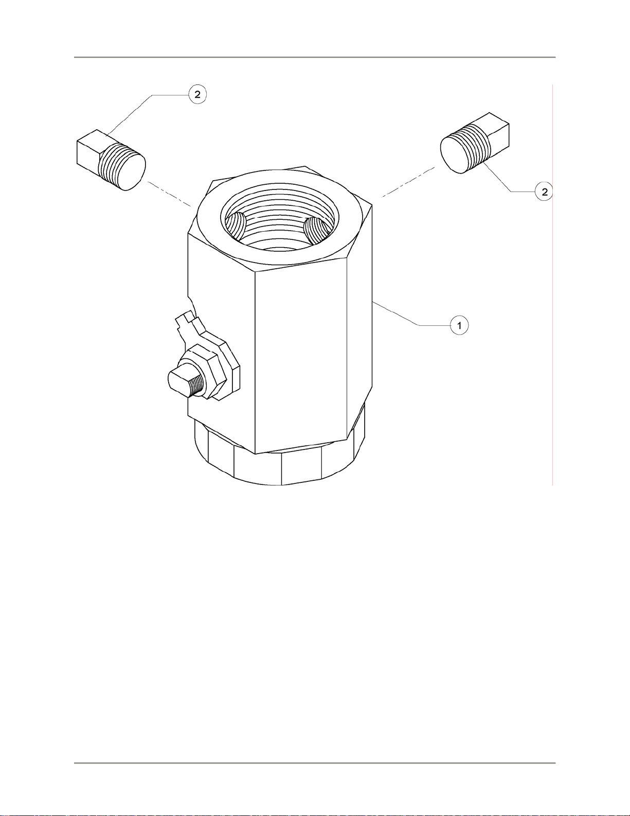
Figure 2. Drain Valve & Plugs
12
Page 15

Automatic Lift Fryer Replacement Parts
Table 2. Drain Valve & Plugs Parts
ITEM # PART # QTY DESCRIPTION
1 MB19101000 1 DRAIN VALVE REPLACEMENT
2 FT0243 2 PLUG, 3/8" SQ HEAD PIPE
13
Page 16

Automatic Lift Fryer Replacement Parts
Figure 3. Drain/Motor/Piping Assembly
14
Page 17

Automatic Lift Fryer Replacement Parts
Table 3. Drain/Motor/Piping Assembly Parts
ITEM # PART # QTY DESCRIPTION
1 MB19101000 1 DRAIN VALVE REPLACEMENT
2 FT0044 1 ELL, STREET 3/8 90 DEG BLACK
3 FT0412 2 NIPPLE, 3/8 NPT X 1 1/2 SCH 40
4 SB1314 1 BALL VALVE ASSY, FRYERS
5 FT0538 1 TEE, 1/2 X 1/2 X 3/8 BLK
6 FT0507 1 CONNECTOR, MALE 10FBU-S NKL PLTD
7 FT0536 3 COUPLING, 5/8 45¦ FLARE TO
8 FT0543 1 DRAIN VALVE BRACKET, FRYERS
9 TU0206 1 TUBING, 29" 1/2" ID
10 TU0205 1 TUBING, 12" 1/2" ID
11 P0070 1 PUMP ONLY FOR HAIGHT MOTOR
12 F0254 2 PIN, COTTER HAIRPIN #213
13 F0255 1 PIN, CLEVIS 3/16 X 1-1/4
14 F0253 1 PIN, CLEVIS 3/16 X 1 3/4
15 SP0014 2 SPACER, ALUM .5 X .125
16 SP0034 2 SPACER, DRAIN VALVE BRKT FRYERS
17 NUT253 2 NUT, 6-32 S/S 18-8 NYLON
18 F0158 1 BUSHING, BLK 1/2 HEYCO SNAP
19 LZ0130 1 SWITCH, ACT. COVER FKMA247
20 S0054 1 SWITCH, MICRO BZ-2RW822-A2
21 H0089 1 HANDLE SUPPORT PLATE
22 N0285 1 DECAL, BLF-F DRAIN HNDL PLATE
23 SCR194 2 SCREW, 6-32 X 1 SL RD HD MS
24 H0215 1 HANDLE, DRAIN VALVE BLF
25 C0672 1 COVER, DRAIN HANDLE RED
26 SCR006 3 SCREW, 8 X 1/2 PHIL PAN HEAD
27 MA19100508 1 FILL VALVE HANDLE, FRYERS
28 C0668 1 COVER, FILL HANDLE BLACK
29 P0081 1 PLUG, F-H4F4-7-7 QUIK DISCONN
30 B0851 1 BUSHING, BLK HEX REDUCING
31 MA19100800 1 TUBING, TEE TO DISCONNECT
32 FT0132 1 ELL, STREET 1/2 90 DEG BLACK
33 M0053 1 MOTOR, LEESON LESS CORD/PUMP
15
Page 18

Automatic Lift Fryer Replacement Parts
Figure 4. Front Panel BLF-F
Table 4. Front Panel BLF-F Parts
ITEM # PART # QTY DESCRIPTION
1 N0523 1 DECAL, CTL PNL BLF-F
2 S0127 1 SWITCH, ROCKER 2P,3 POS
3 S0104 1 SWITCH, RKR DPDT 15A 250V LAMP
4 TI0032 1 TIMER, 230V DIGITAL 4 BUTTON
5 PL0004 1 PILOT LIGHT, ROUND 250V
6 T0075 1 THERMOSTAT, SOLID STATE FRYER
7 K0040 1 KNOB, S/S STRAT T0075
16
Page 19

Automatic Lift Fryer Replacement Parts
Figure 5. Front Panel BLF-FC
Table 5. Front Panel BLF-FC Parts
ITEM # PART # QTY DESCRIPTION
1 N0525 1 DECAL, CTL PNL BLF-FC
2 S0127 1 SWITCH, ROCKER 2P, 3 POS
3 S0104 1 SWITCH, RKR DPDT 15A 250V LAMP
4 CP0039 1 CONTROLLER, VFD LESS HARNESS
17
Page 20

Automatic Lift Fryer Replacement Parts
Figure 6. Rear Panel BLF-F
Table 6. Rear Panel BLF-F Parts
ITEM # PART # QTY DESCRIPTION
1 T0036 1 THERMOSTAT, HI LIMIT 540 DEG
2 TB0064 1 TERM BLOCK 4 CONDUCTOR CTR
3 TB0065 2 TERM BLOCK 4 CONDUCTOR W/MTG FOOT
4 TB0068 1 TERM BLOCK END PLATE
5 TB0069 1 TERM BLOCK JUMPER BAR (not shown)
6 R0148 1 RELAY, 3 POLE 42CF35AG
7 F0158 1 BUSHING, BLK 1/2 HEYCO SNAP
8 F0097 2 FUSE, 15A 300V SC15 TIME DELAY
9 R0134 3 RELAY, MERCURY MDI 60NO220A
10 F0154 2 BUSHING, BLK 1-3/16 HEYCO SNAP
11 F0342 3 CLAMP, CABLE 3/16"
12 FH0001 2 FUSE HOLDER, 15A 300V HPF-EE
13 FT0080 1 CONNECTOR, BOX #7483 1"
14 FT0277 1 PLUG, HOLE 7/8" (1/2" CONDUIT)
15 R0131 2 RELAY. PLUG IN 3PDT 240V COIL
18
Page 21

Automatic Lift Fryer Replacement Parts
Figure 7. Rear Panel BLF-FC
Table 7. Rear Panel BLF-FC Parts
ITEM # PART # QTY DESCRIPTION
1 T0036 1 THERMOSTAT, HI LIMIT 540 DEG
2 R0148 1 RELAY, 3 POLE 42CF35AG
3 TB0064 1 TERM BLOCK 4 CONDUCTOR CTR
4 TB0065 2 TERM BLOCK 4 CONDUCTOR W/MTG FOOT
5 TB0068 1 TERM BLOCK END PLATE
6 R0134 3 RELAY, MERCURY MDI 60NO220A
7 W0054 1 TRANSFORMER ASSY 240V
8 TB0069 1 TERM BLOCK JUMPER BAR (not shown)
9 F0154 2 BUSHING, BLK 1-3/16 HEYCO SNAP
10 R0044 2 RELAY, X-40, SGL FRYER
11 F0097 2 FUSE, 15A 300V SC15 TIME DELAY
12 F0158 1 BUSHING, BLK 1/2 HEYCO SNAP
13 F0342 3 CLAMP, CABLE 3/16"
14 FH0001 2 FUSE HOLDER, 15A 300V HPF-EE
15 FT0080 1 CONNECTOR, BOX #7483 1"
16 FT0277 1 PLUG, HOLE 7/8" (1/2" CONDUIT)
17 R0131 2 RELAY. PLUG IN 3PDT 240V COIL
19
Page 22

Automatic Lift Fryer Replacement Parts
Figure 8. Oil Vat Assembly
20
Page 23

Automatic Lift Fryer Replacement Parts
Table 8. Oil Vat Assembly Parts
ITEM # PART # QTY DESCRIPTION
1 SB1991 1 QUIK DISCONNECT BRACKET WELDMENT
2 O0013 1 O-RING, FLUOROCARBON V680-70
3 WB16010400 1 FILTER VAT TUBE WELD, BLF
4 SB7659 1 FILTER SCREEN FITTING SPOTWELD
5 FS0003 1 FILTER SCREEN, TOP
6 FS0002 1 FILTER SCREEN, INTERCEPTOR
7 FS0001 1 FILTER SCREEN, BOTTOM
8 FC0004 1 NUT SCREEN RETAINING BLF-F &
9 WB16010600 1 FILTER VAT WELD QUIK DISC
10 FKMA357 1 COVER, FILTER VAT
11 N0395 1 DECAL, VAT COVER SAFETY WARN
12 SB7675 1 CRUMB BASKET WELD
Figure 9. Quick Disconnect Assembly
Table 9. Quick Disconnect Assembly Part s
ITEM # PART # QTY DESCRIPTION
1 B0996 1 BALL, 11/16" STEEL BEARING
2 FT0429 1 QUICK DISCONNECT, PUMP SIDE
3 FT0500 1 QUICK DISCONNECT, VAT SIDE
4 FT0536* 1 COUPLING, 5/8 45¦ FLARE TO
5 O0013 2 O-RING, FLUOROCARBON V680-70
6 O0014 1 O-RING, PARKER #2-124 LARGE
7 S0138 1 SPRING, FOR QUICK DISCONNECT
8 SCR453* 2 SCREW, #10 24X3/8" WASHERED
* - Not included with SB1997S
21
Page 24

Automatic Lift Fryer Replacement Parts
Figure 10. Terminal Block Assembly
Table 10. Terminal Block Assembly Parts
ITEM # PART # QTY DESCRIPTION
1 TB0044-N 4 TERM BLOCK TAGS "N"
2 TB0049 1 TERM BLOCK 2 POLE JUMPER
3 TB0048 1 TERM BLOCK GROUND BLOCK
4 TB0047 4 TERM BLOCK END PLATE WAP
5 TB0046 5 TERM BLOCK, WDU10 #102030
6 TB0044-G 2 TERM BLOCK TAGS PIC/GROUND
7 TB0044-C 2 TERM BLOCK TAGS "C"
8 TB0044-B 2 TERM BLOCK TAGS "B"
9 TB0044-A 2 TERM BLOCK TAGS "A"
10 MA10503700 1 RAIL CUT TO 3.94" TB0045
11 TB0051 1 TERM BLOCK END BRKT EW35
22
Page 25

Automatic Lift Fryer Replacement Parts
Accessories
Description Accessory # Figure # Item #
BASKET, BLF B0112 Figure 11 1
BRUSH, DRAIN (LONG WHITE) B0075 Figure 11 2
BRUSH, L TIPPED 40152 B0063 Figure 11 3
BRUSH, POT SCRUBBER, WHITE B0049 Figure 11 4
CORD SET, BLF-FC 7' SB7655 Figure 11 5
FILTER HOSE, FEMALE SOCKET SB2332 Figure 11 6
FILTER VAT DOLLY BLF-F SB7650 Figure 11 7
INSULATED MITT 13" G0052 Figure 11 8
FILTER, FKM-F 13.5 X 20.5 FI0007 Figure 11 9
STORAGE COVER AN16007300 Figure 12 Table 11
Figure 11. Accessories
1 2 3
4 5 6
7 8 9
23
Page 26

Automatic Lift Fryer Replacement Parts
Table 11. Storage Cover Assembly Parts
ITEM # PART # QTY DESCRIPTION
1 FB16009303 1 HANGER, FRY POT COVER BLF
2 SCR136 1 SCREW, 10-24 X 3/8 SLTD TRUSS
3 N0358 1 DECAL, BLF COVER CAUTION
4 K0044 1 KNOB, LARGE COVER, #3200
5 FB16007003 1 COVER, STORAGE BLF TOP
6 N0162 1 DECAL, CAUTION HOT SURFACES
7 SCR007 2 SCREW, 8 X 3/4 PHIL TRUSS HD
8 SCR005 1 SCREW, 8 X 1/2 PHIL TRUSS HD
Figure 12. Storage Cover Assembly
24
Page 27

Automatic Lift Fryer Replacement Parts
Components
Description Component # Figure # Item #
CALROD, 208V 5675W FKM-F
CALROD, 240V 5675W FKM-F
CASTER, W/TOP PLATE 5" C0406 Figure 13 2
CAPACITOR, 7.5 MFD 370 VAC CP0102 Figure 13 3
WASHER, TEFLON-FRYER CALROD FT0059 Figure 13 4
HINGE, SLIP WING RH H0051 Figure 13 5
HINGE, SLIP WING LH H0052 Figure 13 6
BRACKET, CALROD FKMA258 LZ0006 Figure 13 7
BRACKET BACK PLATE FKMA259 LZ0007 Figure 13 8
MOTOR, BALL DRIVE ACTUATOR M0084 Figure 13 9
NUT, 5/8-18 HEX NUT237 Figure 13 10
SWITCH 1A 250VAC SPDT S0353 Figure 13 11
PROBE ASSEMBLY KIT, COMPUTER SB1938 Figure 13 12
THERMISTER PROBE/FTGS ASSEMBLY SB7656 Figure 13 13
FILTER BAG CLIP FKM-F ST0015 Figure 13 14
COLLAR/LIFT ADJ WELD BLF WA16015600 Figure 13 15
BASKET LIFT ARM WELD, LINEAR ACTUATOR WB16015800 Figure 13 16
WASHER, 5/8 INT TOOTH LOCK WSH107 Figure 13 17
Figure 13. Components
C0030
C0031
Figure 13 1
1 2 3
4 5 6
25
Page 28

Automatic Lift Fryer Replacement Parts
7 8 9
10 11 12
13 14 15
16 17
26
Page 29

Automatic Lift Fryer Wiring Diagrams
Wiring Diagrams
Refer to the table below to find the wiring diagram associated with your unit.
Wiring Diagram Figure # Page #
Domestic BLF-F 208V/220V/240V Figure 14 28
European BLF-F 220V/380V, 230V/400V, 240V/415V Figure 15 32
Domestic BLF-FC 208V/220V/240V Figure 16 36
European BLF-FC 220V/380V, 230V/400V, 240V/415V Figure 17 40
27
Page 30

Automatic Lift Fryer Wiring Diagrams
Figure 14. Domestic BLF-F 208V/220V/240V (Sheet 1 of 4)
28
Page 31

Automatic Lift Fryer Wiring Diagrams
Figure 14. Domestic BLF-F 208V/220V/240V (Sheet 2 of 4)
29
Page 32

Automatic Lift Fryer Wiring Diagrams
Figure 14. Domestic BLF-F 208V/220V/240V (Sheet 3 of 4)
30
Page 33

Automatic Lift Fryer Wiring Diagrams
Figure 14. Domestic BLF-F 208V/220V/240V (Sheet 4 of 4)
31
Page 34

Automatic Lift Fryer Wiring Diagrams
Figure 15. European BLF-F 220V/380V, 230V/400V, 240V/415V (Sheet 1 of 4)
32
Page 35

Automatic Lift Fryer Wiring Diagrams
Figure 15. European BLF-F 220V/380V, 230V/400V, 240V/415V (Sheet 2 of 4)
33
Page 36

Automatic Lift Fryer Wiring Diagrams
Figure 15. European BLF-F 220V/380V, 230V/400V, 240V/415V (Sheet 3 of 4)
34
Page 37

Automatic Lift Fryer Wiring Diagrams
Figure 15. European BLF-F 220V/380V, 230V/400V, 240V/415V (Sheet 4 of 4)
35
Page 38

Automatic Lift Fryer Wiring Diagrams
Figure 16. Domestic BLF-FC 208V/220V/240V (Sheet 1 of 4)
36
Page 39

Automatic Lift Fryer Wiring Diagrams
Figure 16. Domestic BLF-FC 208V/220V/240V (Sheet 2 of 4)
37
Page 40

Automatic Lift Fryer Wiring Diagrams
Figure 16. Domestic BLF-FC 208V/220V/240V (Sheet 3 of 4)
38
Page 41

Automatic Lift Fryer Wiring Diagrams
Figure 16. Domestic BLF-FC 208V/220V/240V (Sheet 4 of 4)
39
Page 42

Automatic Lift Fryer Wiring Diagrams
Figure 17. European BLF-FC 220V/380V, 230V/400V, 240V/415V (Sheet 1 of 4)
40
Page 43

Automatic Lift Fryer Wiring Diagrams
Figure 17. European BLF-FC 220V/380V, 230V/400V, 240V/415V (Sheet 2 of 4)
41
Page 44

Automatic Lift Fryer Wiring Diagrams
Figure 17. European BLF-FC 220V/380V, 230V/400V, 240V/415V (Sheet 3 of 4)
42
Page 45

Automatic Lift Fryer Wiring Diagrams
Figure 17. European BLF-FC 220V/380V, 230V/400V, 240V/415V (Sheet 4 of 4)
43
Page 46

Automatic Lift Fryer Notes
Notes
44
Page 47

Automatic Lift Fryer Notes
45
Page 48

P.O. Box 80400, Simpsonville, S.C. 29680-0400, USA
http://www.bkideas.com
Made and printed in the U.S.A
LI0226/0106
 Loading...