

GUIDE TO INSTALLATION
OF THE
B&K
CK2.2 KEYPAD
SBIMPLY ETTER!
BK&
14322 081307

II
SBIMPLY ETTER!
BK
&
Thank you for choosing to install the B&K CK2.2
Keypad for this system!
Please use this manual as a guide to connecting and mounting the CK2.2 Keypad.
The CK2.2 keypad is preprogrammed at the factory to initially operate
B&K CT products. It can be re-programmed using a Windows PC and the
accompanying CD. See the CK2.2 Keypad Programming Manual on the CD for
instructions on programming.
B&K Components, Ltd. sells its products through authorized dealers.
Buying from an authorized B&K Components, Ltd. dealer insures that you
have a FACTORY WARRANTY on your B&K Components, Ltd. product. A
warranty on B&K Components, Ltd. products is NOT VALID if the products
have been purchased from an unauthorized dealer or an E-tailer or if the
factory serial number has been removed, defaced or replaced in any way.
Guide to Installation of the B&K CK2.2 Keypad
© 2007 B&K Components, Ltd. All rights reserved.
B & K Components, Ltd.
2100 Old Union Road
Buffalo, New York 14227
1.800.543.5252 In NY: 716.656.0026
Fax: 716.656.1291
E-mail: info@bkcomp.com
On the web: www.bkcomp.com
SBIMPLY ETTER!
BK&

III
SBIMPLY ETTER!
BK
&
Table of Contents
Table of Contents III
Features and Benefits IV
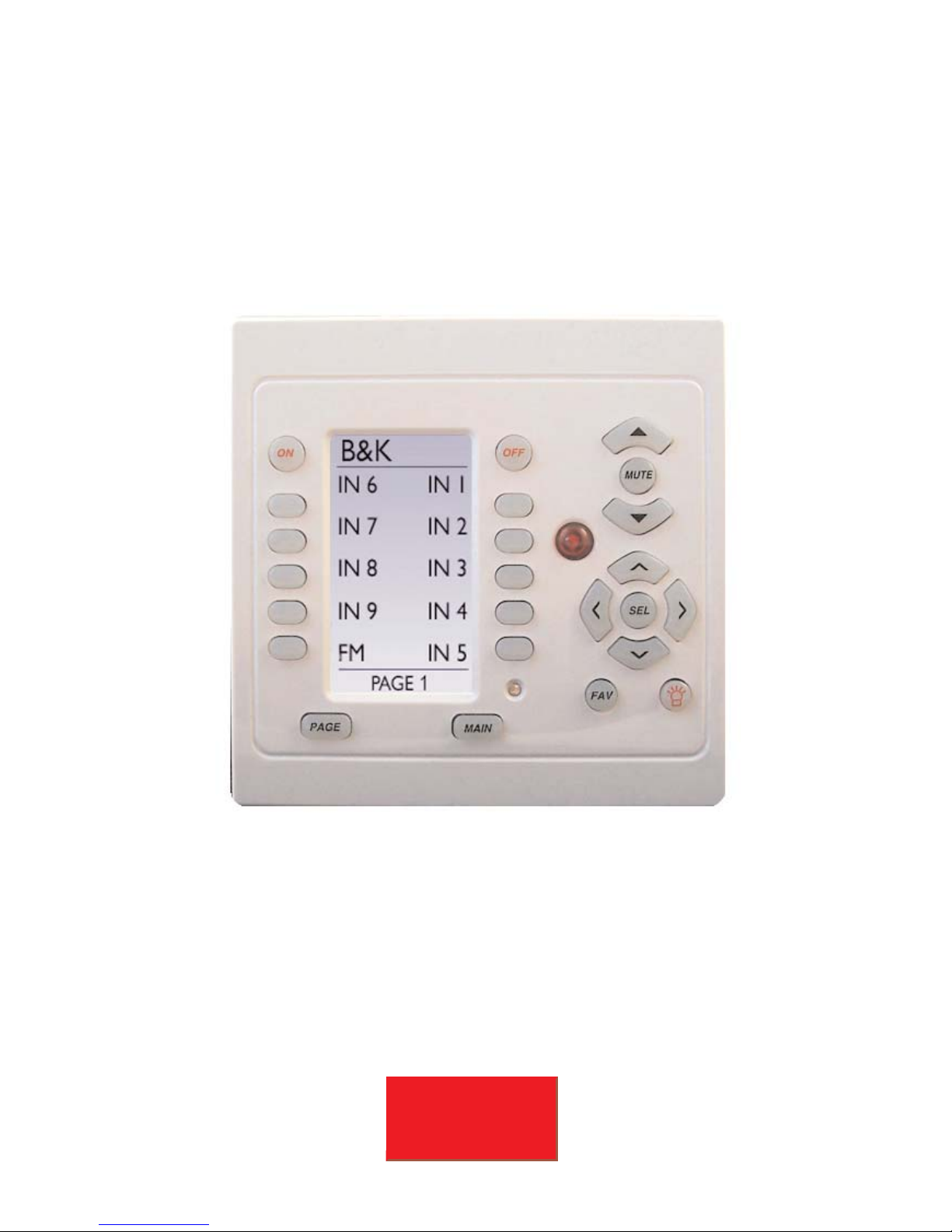
Basic Controls and Displays 1
Standard CT Receiver System 2
Connecting to a CT Receiver 2
Terminate RJ-45’s One to One 3
Keypad Total Power Consumption 3
Connecting Slave Keypads 4
The CK2.2 and B&K Home Theater 4
Connecting a Local Device 5
Using IR “Eyes” with the CK2.2 5
Programming 6
Programming Jack - Behind the Faceplate 6
Mounting 7
White and Beige Faceplates 7
Keypad Dimensions 7
Keypad Specifications 8

Features and Benefits
IV
SBIMPLY ETTER!
BK
&
Programming Capacity
The CK2.2 can be programmed with up to 1500 IR commands or macros,
which can span over 50 separate devices. The On and Off, Volume Up or
Down, and Navigation buttons can additionally be programmed with a command or macro per device. The soft button labels can be customized with
labels up to eleven characters, so the commands or macros will display
user friendly names that are easy to use.
One Touch Automated Operation
The On, Off and all of the soft buttons can be programmed with macros of
up to 190 steps, including IR commands or delays of .1 to 30 seconds.
Point Any Remote Control at the Keypad
The integrated IR pass through allows commands from infrared remotes to
pass through to the back panel and on to other sources using emitters. The
sensor can be disabled using the programming software.
Control Local TV’s and the Central System
By connecting a flasher directly to the keypad, you can program the IR
commands and Macros to control TV’s and other local components placed
in the room.
Two Way Communications With B&K Multi-Zone Receivers
The keypad displays the status of the zone it controls in two ways:
1. The blue status LED indicates when the zone is on or off with typical
CT/Keypad programming and wiring.
2. The keypad will display the current zone status including volume, tone,
input, and tuner band with frequency in real time when the backlight button
is pressed. The zone status key will scroll through the current parameters of
the zone the keypad is connected to.
Multiple Keypads within One Zone
You can daisy-chain multiple keypads within one zone. All keypads will correctly display the zone power status of the zone it is connected to.
Ultra-Fast Programming via PC Software
A vast database of more than one thousand brands instantly programs IR
codes for most components; B&K Batch Learning does the rest in a fraction
of the time of any other system.
Retains Programming through Power Failures
Your programming is safe in the event of a power failure of any length. The
Non-Volatile Flash Memory keeps the program intact.

1
Basic Controls and Displays
SBIMPLY ETTER!
BK
&
Soft Buttons
Drag and drop any command or macro from the
Universal IR Database.
Volume/Mute Buttons
Typically programmed for
control of the audio level.
Navigation Buttons
Backlight Button
Lights the keypad display
and recalls status feedback of the CT Receiver
on the bottom line of the
LCD display.
Power LED
Typically lights up when
the Zone/Room is on.
LCD Display
Labels on the screen
change depending on
what activity has been
selected.
Main Button
Takes the keypad back to
Main Page 1.
Fav Button
Takes the keypad to the
Favorites Page 1.
Page Button
Cycles through the pages
of commands or macros.
On/Off Buttons
Typically programmed for
a command or macro for
power of the Zone or
device.
Remote Control Target
Conceals an IR Sensor which relays commands from a
handheld IR remote to control the main system and
components connected to flahers.
Slave (Out)
Connects to the Master
(In) of any other zone
keypads via straight
CAT-5 cable terminated
with a RJ-45 connector.
Master (In)
Connects to the CT
Receiver Zone Control
I/O via straight CAT-5
cable terminated with
a RJ-45 connector.
Alternate Master In
Mirrors the connectors in
the Master (In) but
usable in a retro-fit
application.
Master Pin Out
1. +12V DC IN
2. KEYPAD IR DATA OUT
3. GROUND
4. N/C
5. RS-232 RECEIVE INPUT
6. GROUND
7. STATUS IN
8. +12VDC IN
Slave Pin Out
1. +12V DC IN
2. KEYPAD IR DATA OUT
3. GROUND
4. N/C
5. RS-232 OUTPUT
6. GROUND
7. STATUS IN
8. +12VDC IN

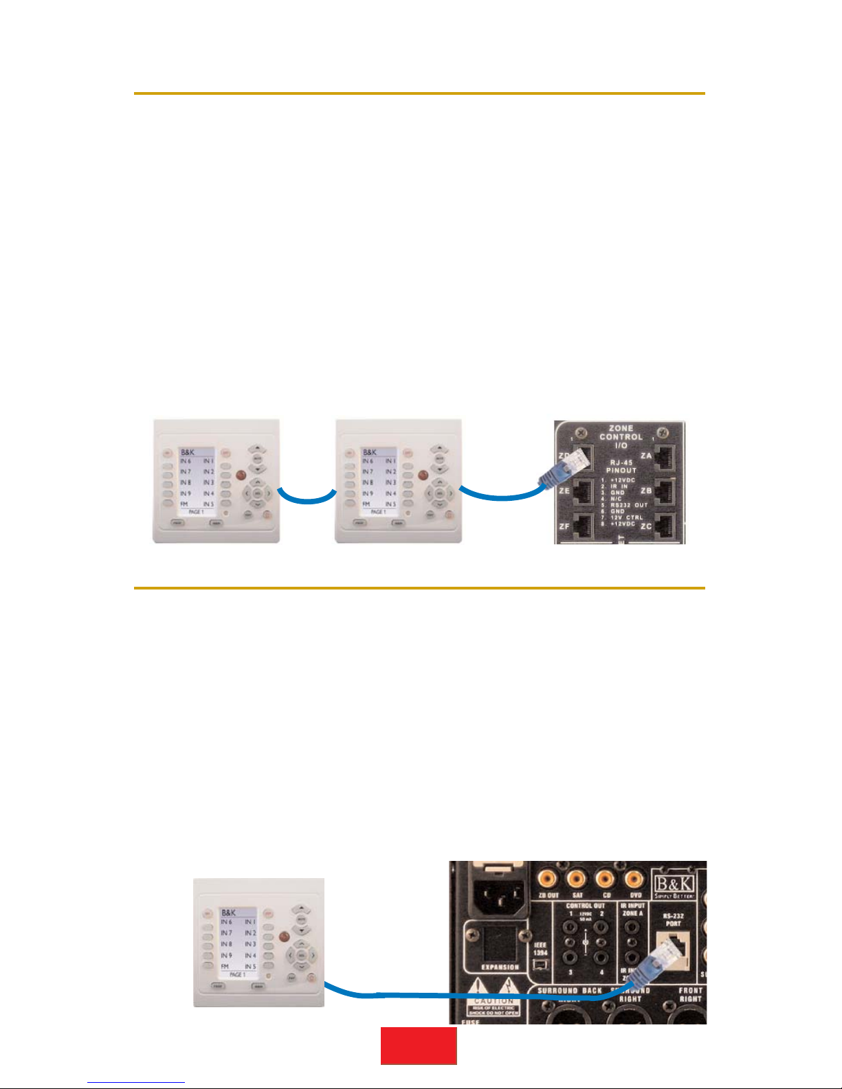
Connecting to a CT Receiver
Standard CT Receiver System
2
SBIMPLY ETTER!
BK
&
Keypads connect to the Zone Control Connectors on the CT Receiver
using CAT-5 cables. CK 2.2 keypads can be coupled with CK 1.1 keypads in any zone.
IR Flashers for A/V components
as connected to the IR output
corresponding to their A/V Input.
The CT Receiver
amplifier channels
connect to each
zone speakers via
speaker wire. Please
see the CT Receiver
manual for more
information.
Keypads connect to the CT Receiver using a straight CAT-5 at the
Zone Control RJ-45 ports. There is one port for each hardware zone,
labeled A through F on the CT 600.3/600.1 and A through C on the
CT300.3.
1. +12V DC IN
2. KEYPAD IR DATA OUT
3. GROUND
4. N/C
5. RS-232 RECEIVE INPUT
6. GROUND
7. STATUS IN
8. +12VDC IN
CT Receiver Zone I/O Ports (A-F)
CK 2.2 Master (In)

RJ-45 Pin Numbers
Keypad Total Power Consumption
Terminate RJ-45’s One to One
3
SBIMPLY ETTER!
BK
&
12
34
5
6
78
Pair 2
Orange
Pair 1
Blue
Pair 4
Brown
Pair 3 Green
EIA-568B Pinout
CK 2.2 MASTER (IN) T568B Standard CT Receiver Zone I/O
1. +12VDC In White/Orange 1. +12VDC Out (Extra)
2. IR Data Out Orange 2. IR Data In
3. Ground White/Green 3. Ground (Extra)
4. N/C Blue 4. N/C
5. RS-232 Receive White/Blue 5. RS-232 Transmit
6. Ground Green 6. Ground
7. Status In White/Brown 7. Control Out
8. +12VDC In Brown 8. +12VDC Out
The six zone CT Receiver 12VDC outputs support a maximum of 20
keypads total, ten keypads to each vertical array of three zone control
connections. Thus, a three zone CT Reciever can support a maximum
of 10 keypads. If power is being supplied to relays, screens or sensors,
these devices must be accounted for and would reduce the total number of potential keypads. Each CK 2.2 keypad consumes 75mA.
Terminate the RJ-45’s using any color code, just connect the cables
straight through, i.e. exactly the same color to pin on each end of the
cable. Standard pre-terminated LAN (Local Area Network) cables work
fine.
For convenience, the T568-B color scheme is listed and shown below. N/C is Not Connected.
Each of the zone/control cards of the CT600.3 are indentical to the single card of the CT
300.3. Zone/Control cards incorporate 3 zone keypad/sensor connectors and 1 common
control output. The total power consumption of all devices attached to one card
cannot exceed 1 amp.
4
SBIMPLY ETTER!
BK
&
The CK2.2 and B&K Home Theater
Connecting Slave Keypads
Each zone should have one CAT-5 cable home run to the CT Receiver.
When rooms interconnect and open to each other (for example interconnecting family room, kitchen, dining areas) you may opt to expand a
zone to include several rooms. Each room can have it’s own keypad.
Many keypads can be connected by a daisy chain configuration in any
zone. Daisy chained keypads can also operate as an independent zone
keypads if desired. Status feedback and power LED will reference the
zone to which it is connected, not the zone it is controlling.
The main system connects to the Master keypad via the MASTER (IN).
From the Master keypads SLAVE (OUT) connect to the Slave keypad’s
MASTER (IN). You can continue to daisy chain as many keypads as
necessary. However, keep in mind that each keypad consumes 75mA of
power. See page 3 for more information on Total Power Consumption.
The CK 2.2 can be easily programmed with the commands for all remote
controlled B&K receivers and preamps. The CK2.2 can be directly connected to the Home Theater product to integrate easily for second zone
or IR source control. When using the CK2.2 with B&K Home Theater
products, zone status will display the same way when the keypad is used
with CT Multi-Zone products.The CK2.2 keypad can be used separately
or be coupled with another keypad, including the CK1.1. Up to two keypads can be directly connected to the the RJ-45 connection on the Home
Theater product. If additional keypads are required, an additional 12VCD
power supply must be used.
Note: Not all features are applicable when keypad (s) are used in systems other than B&K.
To Main System
5
SBIMPLY ETTER!
BK
&
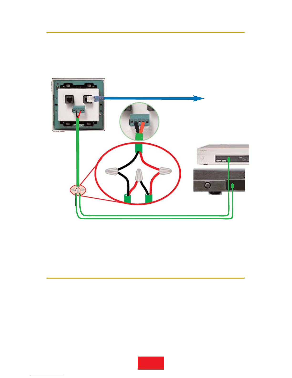
Using IR “Eyes” with the CK2.2
Connecting a Local Device
Every keypad can control a local IR source(s) by directly connecting IR
emitters from the keypad to the local source. A two conductor cable
should be run from the keypad location to the local component location.
Up to four infrared emitters can be wired to a keypad by connecting in
SERIES as shown below.
Multiple emitters shoudl connect in SERIES! When connecting emitters directly to the
keypad, multiple emitters should be connected in series. A maximum of 4 emitters can be
connected directly to the CK 2.2 keypad. Additional resistance is not necessary when
directly connecting emitters to the CK 2.2 keypad. Wire requirements for emitters vary.
Standard 2 conductor speaker wire is ideal for long runs from the keypad to a local
device. Utilizing CAT-5 cable will also work well.
Sometimes additional IR receivers are required in some rooms in addition to the CK 2.2 keypad. If additional IR recievers are used in a zone,
they should be treated like a slave keypad. Run a cable from the CK 2.2
to the IR receiver in the zone. The IR receiver should be pinned from
the Alternate Master (In) of the CK 2.2 keypad according to the connection figure below.
IR Receiver
CK 2.2 Alternate Master (In)
IR Data Pin 4
IR Data In
Ground Pin 2
Ground
+12VDC Pin 1
+12VDC
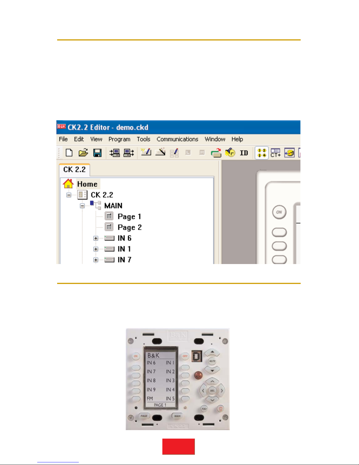
Programming Jack - Behind the Faceplate
Programming
6
SBIMPLY ETTER!
BK
&
Use the included CD-ROM to install B&K’s Keypad editor on your
Windows PC. The CK2.2 Editor runs on Windows 2000, XP, XP Pro and
Windows Vista. It is best to do all programming in front of the components with a CK2.2 connected to a laptop’s USB port. Each keypad
must have its own program downloaded to it. To program, simply open
the CK2.2 Editor, go to the Program Menu and work your way through
the programming steps. See the CK2.2 Programming Manual on the
included CD for more information.
The faceplate is removed by pulling the magnetic faceplate from the
base of the keypad. Once removed, the programming jack is revealed.
The CK 2.2 keypad is programmed using a USB port on a laptop with
the USB cable that is provided.

0.475”
Keypad Dimensions
White and Beige Faceplates
Mounting
7
SBIMPLY ETTER!
BK
&
Once programming is complete and downloaded to each keypad, finish
the installation by installing either the white or the beige faceplate. The
wall plate magnetically fits into place, first from the top and finishing with
the bottom.
After connections are made, the CK2.2 installs into a standard double
gang J-Box or an open backed double gang trim ring with the screws
provided. If you opt to use a closed J-Box, it must be a minimum of 2 3/4”
deep to accomodate standard RJ-45 plugs in the rear. It is easiest to
mount the keypad in an open backed trim ring as shown below.
Often the best solution to mounting a B & K keypad are the mounting plate brackets for Low
Voltage Class 2 devices made by Caddy, B-Line
etc. Of course, enclosed J-Boxes can be used,
they must be deep enough to accomodate the
depth of the RJ-45 connectors plugged into the
rear of the keypad (2 3/4”).
3.563”
2.875”
4.687”
4.75”
2.265”

SBIMPLY ETTER!
BK&
B &K Components, Ltd.
2100 Old Union Road
Buffalo, New York 14227
1.800.543.5252 In NY: 716.656.0026
Fax: 716.656.1291
E-mail: info@bkcomp.com
On the web: www.bkcomp.com
Compatible B& K products:
B&K Receivers, Preamp Processors
and Infrared controllable equipment.
Operating Voltage and Current: 12VDC @ 75mA
Master Input and Type:
1 RJ-45 and one 5-position phoenix
adapter (Alternate Master)
Slave Output and Type: 1 RJ-45
Front Panel IR Pass Yes
Local Emitter Capability: Yes
Included Faceplates: White and Beige
Available Faceplates: TBD
Installation Requirement Standard Double Gang
Keypad Dimensions
Height (Faceplate)
Width (Faceplate)
Depth
4.687”
4.75”
2.265”
Keypad Specifications
 Loading...