

Page 1

B&K Components, Ltd.
User Manual
R
EFERENCE 5 S2
Stereo Preamplifier Tuner
13742 0704
Page 2

ii
SB
IMPLY ETTER!
BK
&
USER MANUAL - REFERENCE 5 S2
© 2004 B&K Components Ltd. All rights reserved.
ACCESSORIES AND WARRANTY
The information in this manual is copyright protected. No part of this manual may be copied or reproduced in any form
without prior written consent from B&K Components, Ltd.
B&K Components Ltd. SHALL NOT BE LIABLE FOR OPERATIONAL, TECHNICALOR EDITORIAL
ERRORS/OMISSIONS MADE IN THIS MANUAL. The information in this manual may be subject to change
without prior notice.
Accessories Included
1 - Reference 5 S2
1 - User Manual
1 - Remote Control
1 - AM Antenna
1 - Power Cord
1 - Warranty Card
1 - FM Antenna
SIMPLYBETTER! is a registered trademark of B&K Components, Ltd. All other brand or product names are trademarks or registered trademarks of
their respective companies or organizations.
Limited Warranty
B &K Components Ltd., referred to herein as B&K, warrants your B&K equipment against all defects in material and workmanship for a period of five
years from the date of purchase. This warranty applies only to the original purchaser and only to equipment in normal residential use and service.
Defective equipment must be returned to B& K, prepaid, accompanied by proof of purchase and sufficient payment to cover the cost of return shipping
and handling, and will be repaired or replaced at the discretion of B &K whose decision as to the method of reparation will be final.
This warranty shall not apply to any equipment which is found to have been improperly installed, incorrectly fused, misused, abused, or subjected to
harmful elements, used in any way not in accordance with instructions supplied with the unit, or to have been modified, repaired or altered in any way
without the expressed, written consent of B& K. This warranty does not apply to the cabinet or appearance items such as the faceplate or control buttons, nor does it cover any expenses incurred in shipping the unit to and from the manufacturer's service department.
This warranty on B& K Components, Ltd. products is NOT VALID if the products have been purchased from an unauthorized dealer or an E-tailer or if
the original factory serial number has been removed, defaced or replaced in any way. B&K Components, Ltd. sells its products through authorized
dealers in order to insure that consumers obtain proper dealer service and support. Buying from an authorized B&K Components, Ltd. dealer insures
that you have a FACTORY WARRANTY on your B&K Components, Ltd. product. If you have any questions concerning your Factory Warranty call
B &K Components, Ltd. at 716-656-0026.
Upgradability: B& K is one the first manufacturers in the audio/video industry to consistently offer software and hardware upgrades to its processing of
audio signals. Through upgrades B&K delivers exceptional value to its customers. But what is "Upgradability"? Upgradability is not a guarantee; we
define it as a philosophy of designing and manufacturing products so that as audio technology evolves, B &K can provide enhancements and improvements to its products that are economically viable.
THE EXPRESS FACTORY WARRANTY HEREIN CONTAINED IS IN LIEU OF ANYAND ALL OTHER WARRANTIES, EXPRESSED OR IMPLIED,
INCLUDING ANY WARRANTY OF MERCHANTABILITY, UPGRADABILITY OR OF FITNESS FOR ANY PARTICULAR PURPOSE. B&K COMPONENTS, LTD. SHALLNOT UNDER ANY CIRCUMSTANCES BE LIABLE FOR DAMAGES, INCLUDING SPECIAL, INCIDENTAL, EXEMPLARY, PUNITIVE OR CONSEQUENTIAL DAMAGES ARISING OUT OF OR IN CONNECTION WITH THE PURCHASE, USE OR PERFORMANCE OF ANY B &K
PRODUCT
This warranty gives you specific legal right
limitation of incidental or consequential damages and the foregoing exclusions may not apply to you.
No agent, representative, dealer or employee of B &K has the authority to increase or alter the obligations or terms of this warranty.
.
our may also have other right
Y
s.
s which vary from State to State. Some States do not allow the exclusion or
Returning Equipment
No equipment may be returned to
ment to B &K, for any reason, a RETURN AUTHORIZATION (RA) number must be issued by B&K in respect of the equipment being returned. You
may request an RA
ready before you call.
1.
2. The model and serial number of the equipment being returned.
3. A description of the problem being experienced.
4. Your sales receipt.
Your call will be referred to a
returned for rep
number by calling B& K at the numbers below. We will need the following information to issue your RA number. Please have it
our name, address, and phone number
Y
, an RA
air
2100 Old Union Road Buf
B &K Components Ltd. without a RETURN AUTHORIZATION (RA). Should you find it necessary to return equip-
.
echnical Service Represent
T
number will be issued.
e-mail: info@bkcomp.com Web Site: www
ative who will work with you to resolve the problem. If it is determined that the unit must be
falo, NY 14227 1-800-543-5252 In NY: 716-656-0026 fax: 716-656-1291
.bkcomp.com
Page 3

TABLE OF CONTENTS
ACCESSORIES AND WARRANTY ii
TABLE OF CONTENTS 1
SAFETY PRECAUTIONS 2
PREAMPLIFIER FEATURES 3
FRONT PANEL DESCRIPTION 4
BACK PANEL DESCRIPTION 5
SYSTEM CONNECTIONS 6
SOURCE CONNECTIONS 6
SPEAKER CONNECTIONS 7
FIVE POSITION PHOENIX CONNECTOR 8
KEYPAD or IR SENSOR CONNECTION 8
AMPLIFIER CONTROL TRIGGER 8
UNIT OPERATION 9
POWER ON/OFF 9
ON/STANDBY 9
ADJUSTING VOLUME 9
CHOOSING ASOURCE 9
ADJUSTING BALANCE 9
ADJUSTING BASS, TREBLE and LOUDNESS 10
TUNER OPERATION 10
HEADPHONE MODE 10
BKcSuite SETUP SOFTWARE 11
PRESETS 11
1
THE MENU SYSTEM 12
DESCRIPTIONS OF MAIN MENU SELECTIONS 12
FACTORY RESET 13
MAIN SETUP MENU FLOW DIAGRAM 14
ADVANCED MENU 15
TROUBLESHOOTING 16
ADVANCED SETUP MENU FLOW DIAGRAM 1
SPECIFICATIONS Back
Page 4

2
CAUTION
R
ISKOFELECTRICSHOCK
D
ONOTOPEN
SAFETY PRECAUTIONS
Installation Considerations
PLEASE READ BEFORE INSTALLING
WARNING: To prevent fire or shock hazard, do not expose this unit to rain or moisture. Care should
be taken to prevent objects or liquid from entering the enclosure. Never handle the power cord with
wet hands.
··
The lightning flash with arrowhead, within an equilateral triangle, is intended to alert the user of the
presence of uninsulated "dangerous voltage" within the product's enclosure that may constitute a risk
of electric shock to you.
··
The exclamation point within an equilateral triangle is intended to alert the user of the presence of
important operating and maintenance (servicing) instructions in the literature accompanying the unit.
··
Caution: To prevent the risk of electric shock, do not remove cover. No user-serviceable parts
inside. Refer servicing to qualified service personnel.
··
Unplug the Preamplifier Tuner from the AC outlet when plugging in or unplugging cables, when left
unused for an extended period of time, when moving, or when you suspect lightning in your area.
··
Prevent damage to the power cord. Do not bend, pull, place objects on, alter, etc. Replace the
power cord if it becomes damaged. Always grasp the plug on the power cord when plugging in or
unplugging the Preamplifier Tuner from the AC outlet.
··
Your system may produce sound levels capable of causing permanent hearing loss. Do not operate
for extended periods of time at high volume levels.
··
Make sure the Preamplifier Tuner is placed on a level surface.
··
The Preamplifier Tuner is equipped with raised feet to provide ventilation, reduce acoustic feedback,
and provide protection against scratching the surface the unit is resting on. Do not remove them.
··
Do not stack anything on top of the preamplifier tuner (processor, source, etc.) Leave a minimum of
2" clearance from the top of the Preamplifier Tuner to the next shelf (or component) to insure proper
ventilation.
··
The Preamplifier
··
Do not perform any internal modifications to the Preamplifier Tuner.
··
Always connect the preamplifier power cord to a dedicated AC outlet for normal operation.
··
If young children are present, adult supervision should be provided until the children are capable of
Tuner should be located away from other sources that may be sensitive to heat.
following all rules for safe operation.
··
aking CONTROL OUTPUT or CONTROL INPUT connectors for audio/video inputs or outputs
Mist
may damage your Preamplifier or other components.
··
back music processed by the Preamplifier
handling not only the average power being delivered by the power amplifiers, but also the peak power
that is likely to be generated during strong passages. If you are unsure of your speaker's power rating,
contact the speaker manufacturer or the dealer where you purchased them.
··
Damage may occur to your speakers when the power rating of the driver is exceeded while playing
. Ensure that all the drivers in your system are cap
able of
The Preamplifier Tuner should be serviced by qualified personnel when:
A. The Preamplifier Tuner is not functioning properly.
B. The Preamplifier Tuner was exposed to rain or other type of moisture.
C.
The Preamplifier
Tuner was dropped, or the chassis is damaged.
Page 5

PREAMPLIFIER FEATURES
Your new Stereo Preamplifier Tuner is a versatile audio control center. The Preamplifier Tuner is designed to
sound sensational and be an attractive, easy-to-use addition to your audio system. The Reference 5 S2
makes an excellent addition to any home or office. B&K products are designed and hand assembled at the
facilities in Buffalo New York, USA.
Remote Control Operation - Easy control of your B&K Preamplifier Tuner.
CK1.2 Keypad Interface - One 5-pin phoenix plug allows a CK1.2 Keypad to control the Reference 5 S2.
Headphone Jack - 1/4” (6.3mm) headphone jack available for private listening time.
Front Panel Operation - Most functions can be controlled from the Preamplifier Tuner front panel.
Analog (RCA) Inputs/Outputs - Six audio source inputs. One full range output. One high pass output. One
low pass output (subwoofer). One summed left and right mono output. One tape loop output.
Balanced (XLR) Full range outputs - One pair of balanced outputs deliver the quietest and most accurate
signal path between the preamplifier and amplifier.
Gold Plated Connectors - Better sound quality with minimumized signal loss and degradation.
3
Presets - 40 user presets allow instant recall of any user setting including AM, FM or source input.
Loudness - May be used to add clarity to the audio signal for low to moderate listening levels.
Bass - May be adjusted for better room acoustics.
Treble - May be adjusted for better room acoustics.
Customized Input and Present Names - Assign names to presents, inputs, or the turn on message.
Internally Digitally Synthesized AM/FM Stereo Tuner
IR Output - One IR output allows integrating the Preamplifier Tuner with an infrared emitter control system.
Control I/O - A
power source, one Infrared data input signal, one RS-232 transmit for keypad status and one 12 VDC programmable trigger for amplifiers.
BKcSuite Integration - B&K setup software allows the user to configure and save user preferences and presets using a PC. BKcSuite software is availible online at www
RS-232 Controllable - RS-232 Two Way communication allows for enhanced system control, interface with
BKcSuite or an RS-232 controller.
single 5 pin plug-in Phoenix connector allows easy system access to the preamplifiers 12VDC
.bkcomp.com.
Available Faceplates
andard)
17” Black (S
17” Silver (Optional)
19” Black Rack Mount (Optional)
19” Silver Rack Mount (Optional)
t
Page 6
4
CD -30 DBCD -30 DB
M
ASTER
P
OWER
O
N/STANDBY PRESET
E
NTER
S
OURCE LOUDNESS
T
UNEDOWN
T
UNEUP
L
EVEL
S
AVE
S
2
B
&KCOMPONENTS,LTD.
STEREO PREAMPLIFIER
REFERENCE5
t
1
2
3 4 5
↵
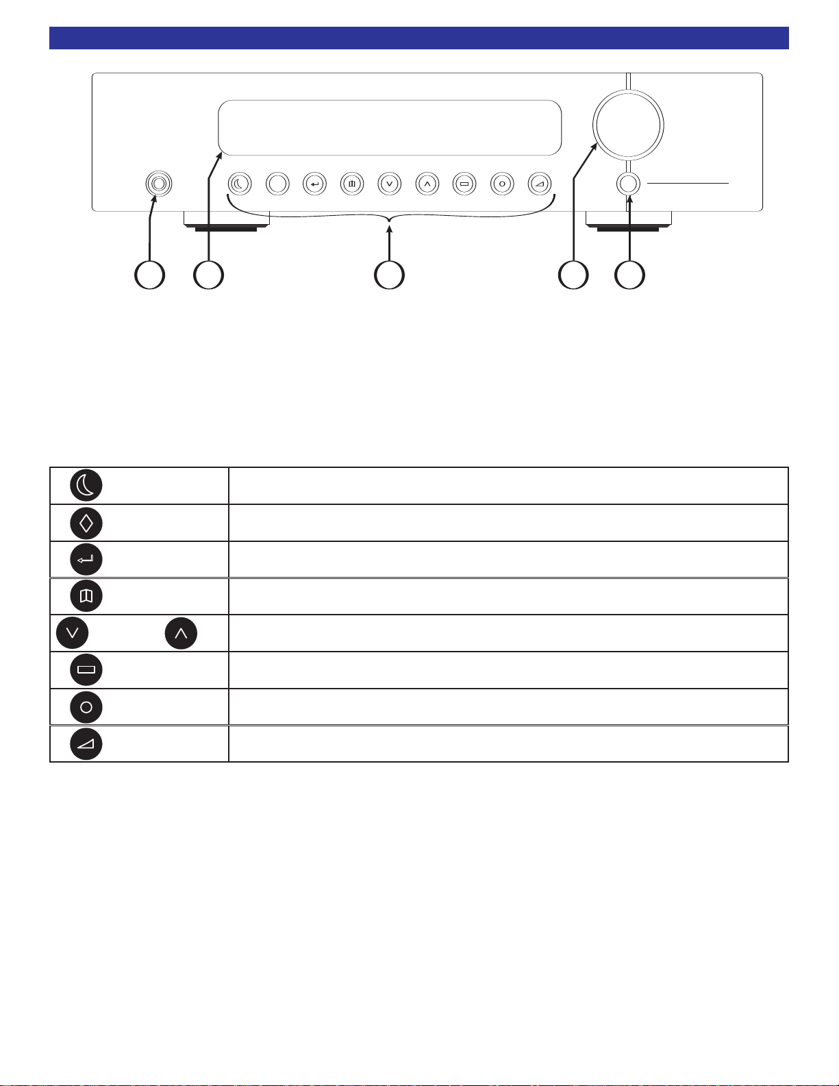
FRONT PANEL DESCRIPTION
1. Headphone Jack - Stereo headphones having a standard ¼” (6.3mm) stereo jack can be connected to the
headphone output. The Preamplifier Tuner must be on and in HEADPHONE Mode for proper headphone
operation.
2. Front panel Display - The Preamplifier Tuner display is a 16 character alphanumeric fluorescent display. It
will display current status of the Preamplifier Tuner and any changes being performed.
3. Front Panel Buttons - The following table outlines front panel button operation.
ON/STANDBY
PRESET
ENTER
SAVE
DOWN UP
SOURCE
LOUDNESS
LEVEL
Toggles the preamplifier in and out of standby mode, (ON or OFF).
Steps through audio presets for instant preset recall.
Press ENTER to recall preset.
Confirm Selection
Press ENTER and PRESET simultaneously to access the menu system.
Save a preset.
Press ENTER to confirm.
Allows radio tune - (down) or tune + (up) of the AM/FM tuner.
When in menu, steps through menus, sources or characters.
Steps through source inputs.
Engages a loudness curve (high and low boosted) for low level listening.
Selects VOLUME, BALANCE, BASS or TREBLE level to be adjusted via the
rotational encoder knob.
4. Volume control - For controlling system volume. Turning the rotational encoder control clockwise increas-
es the volume level, counterclockwise decreases the volume level. The volume knob is also used to change
uner and preamplifier settings when in the menu system.
T
other
5. Master power switch - Shuts off all power to the Preamplifier Tuner. Normal operation of the
Preamplifier Tuner requires the master power switch to remain on. Use the ON/STANDBY button for
daily ON and OFF. Only turn the Preamplifier Tuner off with the master power switch when not using it for an
extended period of time.
Page 7

BACK PANEL DESCRIPTION
V1V2TV
SOURCE INPUTS
DVD
CD
INPUT
OUTPUT
T
APE
PREAMP OUTPUTS
FULL
RANGE
HIGH
PASS
S
UB
M
ONO
L+R
Audio/Video Systems Hand-Made in the U.S.A.
BK
&
SB
IMPLY ETTER!
R
ISKOFELECTRICSHOCK
DONOTOPEN
CAUTION
A
NTENNA
AM
F
M
V
OLTAGE
RS-232
IR
OUTPUT
BALANCEDOUTPUT
FULLRANGE
L
EFT
R
IGHT
S
ERIAL #
G
R
O
U
N
D
R
S
2
3
2
T
R
A
N
S
M
I
T
I
R
D
A
T
A
I
N
P
U
T
C
O
N
T
R
O
L
O
U
T
+
1
2
V
A
C LINE
2
00 mA Max
C
urrent @ 12V
1 2 3 4 5 6 7 8 9 10 11
22
11
3
3
PIN1(GND)PIN 1 (G ND)
PIN3(-)PIN 3 (- )
PIN2(+)PIN
2 (+ )
BalancedInterconnectCable
12
3
PIN1(GND)PIN 1 (G ND)
PIN3(-)PIN
3 (- )
PIN2(+)PIN
2 (+ )
PreamplifierBalancedOutputConnector
The Preamplifier Tuner's back panel is organized into groups of inputs and outputs as shown above.
1. AC Input Receptacle - For attaching the supplied AC power cord to the Preamplifier Tuner. The
serial number of your unit is located below the AC input receptacle. AC line fuse rating - .5A 250V
2. RS-232 - RS-232 Two Way communication allows enhanced system control and BKcSuite interface.
3. IR output - IR signals received by your Preamplifier's front panel or the Infrared Data/Signal input
pin are repeated out this IR connector 1/8” (3.5mm) mono.
5
4. Control I/O - Allows connections to a zone keypad/IR sensor via a 5 pin plug-in Phoenix connector. Also
supplies a control voltage for an amplifier.
+12V - +12VDC Power to Keypad or IR Sensor
Ground - Common Ground
RS-232 Xmit - RS-232 One Way Transmit Out
Data In - Infrared Data Input
CTRL Out - 12VDC Programmable Control Out
5. FULL RANGE Balanced (XLR) output - Variable preamp outputs for driving an external power
amplifier.
Pin 1 - ground
Pin 2 - POS +
Pin 3 - NEG -
6. MONO L+R and SUB PREAMP (RCA) outputs - Variable level outputs for driving external power
amplifiers or powered speakers. Mono is the summation of the L+R full range audio signals. It is then
processed by a low-pass filter to reduce audio above 80 Hz to source the SUB output.
7. HIGH PASS (RCA) output - Variable preamp outputs for driving external power amplifiers or powered speakers.
80 Hz. Use these output
These outputs have been processed through a high pass filter to reduce audio below
s for small speakers or in a subwoofer / satellite system. Note: these output
s
are identical to the full range outputs with the addition of an 80 Hz 12 dB / Octave high-pass filter.
8. FULL
9. TAPE inputs and output - Line level input and fixed output for use with an audio recorder. Tape
Output supplies a return loop for the source input selected.
10. Source line input
11. Antenna inputs - Connections for the AM and FM antennas.
RANGE (RCA) output -Variable preamp outputs for driving external power amplifiers.
s -
t and right connections from your audio sources.
Lef
Red RCA jacks = Right analog audio
White RCA
jacks = Lef
t analog audio
Page 8

6
V1V2TV
SOURCE INPUTS
DVD
CD
ConnecttoCDPlayer
LeftandRightOutput
Reference5S2SourceInputs
051:23:45
V1V 2TV
SOURCE INPUTS
DVD
CD
INPUT
OUTPUT
TAPE
OUT to
tape
recorder
Source
Input(s)
Reference5S2 TapeLoop
MAKING THE CONNECTION
SYSTEM CONNECTIONS
It's tempting to plug in your new Preamplifier Tuner and have great sound pour out. Before you do that, take
a few minutes to plan out how you want the Preamplifier Tuner to fit into your audio system. Keep the following suggestions in mind:
··
List all components in your system and indicate which jacks of the Preamplifier Tuner each component will be connected to. Your Preamplifier Tuner has six sets of inputs. It is convenient to connect a
DVD player to the input labeled DVD or a VCR to the input labeled V1 or TAPE, etc. However, your
equipment may differ from the labeling on the back of your Preamplifier Tuner. In most cases you can
connect any type of source to any input. For example, if you have a satellite receiver you can connect
it to V2. You can also reprogram the source name that will appear on your Preamplifier Tuner's front
panel.
··
Also note the length of the cable for each component's connection and describe how it should be
routed. You may want to label each cable with a name or number at both ends. Use high quality connections to maintain high quality audio.
··
Think about the type and length of cable you need and obstacles in the cable's path (doorways, furniture, walkways, etc.). To decide which ones are right for you talk to your dealer about the various
cable products that are available.
··
For safety, keep all cables out of high traffic areas (hallways or doorways) and away from equipment that radiates power, including amplifiers, power cords, heaters, etc.
··
If you might expand your audio system later, keep these ideas in mind as you plan current cable runs.
··
To provide the best tuner reception, make sure the antenna is at least 6 ft away from the
Preamplifier Tuner and any other equipment that may produce high frequency interference such as
Personal computers, CD players, halogen lamps, etc.
SOURCE CONNECTIONS
To connect your analog sources to your Preamplifier Tuner, take a look at the back panel. You will notice that
the RCA-type audio input and output connectors are identified by colors, RED for right channel and WHITE
for the left channel audio.
Audio source Input - To connect a source such as a CD player
to the Preamplifier
outputs from the CD player. Attach one end of the audio interconnect
cable to the left (White) audio output on the CD player, then attach
the other end to the left (white) CD audio input on the Preamplifier
. Repeat for the right (red) audio connection. Use theses same
uner
T
instructions for connecting to other audio sources such as a DVD, tel
evision, satellite receiver, cable box, etc.
Tuner's analog inputs, use the analog left and right
-
TAPE or audio recorder - Connect a cassette deck or
other recording device to TAPE OUTPUT.
Attach one end of the audio interconnect cable to the left (white)
audio input on the TAPE recorder, then attach the other end to
the lef
Repeat for the right (red) audio connection. TAPE OUTPUT will
output only the audio source selected.
t (white)
TAPE audio output on the Preamplifier Tuner.
Page 9

SPEAKER CONNECTIONS
V
1V2TV
S
OURCE INPUTS
DVD
C
D
I
NPUT
O
UTPUT
T
APE
P
REAMP OUTPUTS
F
ULL
R
ANGE
H
IGH
PASS
SUB
M
ONO
L
+R
A
udio/Video Systems Hand-Made in the U.S.A.
BK
&
S
B
I
MPLY ETTER!
R
ISKOFELECTRICSHOCK
D
ONOTOPEN
CAUTION
ANTENNA
A
M
F
M
V
OLTAGE
R
S-232
I
R
OUTPUT
B
ALANCEDOUTPUT
FULLRANGE
L
EFT RIGHT
S
ERIAL #
G
R
O
U
N
D
R
S
2
3
2
T
R
A
N
S
M
I
T
I
R
D
A
T
A
I
N
P
U
T
C
O
N
T
R
O
L
O
U
T
+
1
2
V
AC LINE
2
00mA Max
C
urrent@ 12V
F
U
S
E
F
U
S
E
F
U
S
E
F
U
S
E
F
U
S
E
F
U
S
E
F
U
S
E
F
U
S
E
F
U
S
E
F
U
S
E
F
U
S
E
F
U
S
E
FUSE
CAUTION: FOR CONTINUED
PROTECTION AGAINST RISK
OF FIRE REPLACE ONLY WITH
S
AME TYPE AND RATING.
CHANNEL 2 OUTPUTCHANNEL 1 OUTPUT
CHANNEL 1 INPUT CHANNEL 2 INPUT
C
TRL
O
UT
12VDC
2
00mA
CONTROLINALL
OW
SAMPLIFIER
OPERA
TIONW
HENA5-24VSIGNAL
ISAPPLIEDW
ITHA3.5mmMINIJACK
X
LR (BALANCED)
RCA (UNBALANCED)
X
LR (BALANCED)
RCA (UNBALANCED)
R
CA INPUT
XLR INPUT
R
CA INPUT
BK
&
S
B
IMPLY ETTER!
S
ERIAL #
CTRL
I
N
CAUT ION
R
ISKOFELECTRICSHOCK
D
ONOTOPEN
R
ISKOFELECTR ICSHOCK
D
O
NOTO
PEN
AC LINE
P
OSITIVE
N
EGATIVE
P
OSITIVE
N
EGATIVE
C
ONTROL I/O
www.bkcomp.com
High Performance
Audio/Video Systems
Hand-Made in the U.S.A.
+
1
2
VL
O
WP
O
W
E
R
R
I
N
G
T
I
P
G
R
O
U
N
D
S
L
E
E
V
E
+
1
2
VC
T
R
LE
N
A
B
L
E
XLR INPUT
Reference200.2S2
Reference5S2
L
L
R
R
R
R
L
L
L
L
L
L
V
1V2TV
S
OURCE INPUTS
DVD
C
D
I
NPUT
O
UTPUT
T
APE
P
REAMP OUTPUTS
F
ULL
R
ANGE
H
IGH
P
ASS
SUB
M
ONO
L
+R
A
udio/Video Systems Hand-Made in the U.S.A.
BK
&
SB
I
MPLY ETTER!
R
ISKOFELECTRICSHOCK
D
ONOTOPEN
C
AUTION
ANTENNA
A
M
F
M
V
OLTAGE
RS-232
I
R
O
UTPUT
B
ALANCEDOUTPUT
FULLRANGE
L
EFT RIGHT
S
ERIAL #
G
R
O
U
N
D
R
S
2
3
2
T
R
A
N
S
M
I
T
I
R
D
A
T
A
I
N
P
U
T
C
O
N
T
R
O
L
O
U
T
+
1
2
V
A
C LINE
2
00mA Max
C
urrent@ 12V
F
U
S
E
F
U
S
E
F
U
S
E
F
U
S
E
F
U
S
E
F
U
S
E
F
U
S
E
F
U
S
E
F
U
S
E
F
U
S
E
F
U
S
E
F
U
S
E
FUSE
C
AUTION: FOR CONTINUED
P
ROTECTION AGAINST RISK
OF FIRE REPLACE ONLY WITH
S
AME TYPE AND RATING.
CHANNEL 2 OUTPUTCHANNEL 1 OUTPUT
C
HANNEL 1 INPUT CHANNEL 2 INPUT
C
TRL
O
UT
1
2VDC
2
00mA
CONTROLINALL
OW
SAMPLIFIER
OPERA
TIONW
HENA5-24VSIGNAL
ISAPPLIEDW
ITHA3.5mmMINIJACK
X
LR (BALANCED)
RCA (UNBALANCED)
X
LR (BALANCED)
RCA (UNBALANCED)
R
CA INPUT
X
LR INPUT
R
CA INPUT
BK
&
SB
I
MPLY ETTER!
S
ERIAL #
C
TRL
I
N
CAUT ION
R
ISKOFELECTRICSHOCK
D
ONOTOPEN
R
ISKOFELECTR ICSHOCK
D
O
NOTO
PEN
A
C LINE
POSITIVE
N
EGATIVE
POSITIVE
N
EGATIVE
CONTROL I/O
www.bkcomp.com
H
igh Performance
A
udio/Video Systems
Hand-Made in the U.S.A.
+
1
2
VL
O
WP
O
W
E
R
R
I
N
G
T
I
P
G
R
O
U
N
D
S
L
E
E
V
E
+
1
2
VC
T
R
LE
N
A
B
L
E
X
LR INPUT
Reference200.2S2
Reference5S2
L
L
V1V2T V
SOURCE INPUTS
D
VD
CD
I
NPUT
OUTPUT
T
APE
PREAMP OUTPUTS
FULL
RANGE
HIGH
PASS
S
UB
MONO
L+R
Audio/Video Systems Hand-Made in the U.S.A.
BK
&
S
B
IMPLY ETTER!
RISKOFELECTRICSHOCK
D
ONOTOPEN
C
AUTION
A
NTENNA
A
M
F
M
VOLTAGE
R
S-232
IR
OUTPUT
BALANCEDOUTPUT
FULLRANGE
L
EFT RIGHT
SERIAL #
G
R
O
U
N
D
R
S
2
3
2
T
R
A
N
S
M
I
T
I
R
D
A
T
A
I
N
P
U
T
C
O
N
T
R
O
L
O
U
T
+
1
2
V
AC LINE
2
00mA Max
C
urrent@ 12V
F
U
S
E
F
U
S
E
F
U
S
E
F
U
S
E
F
U
S
E
F
U
S
E
F
U
S
E
F
U
S
E
F
U
S
E
F
U
S
E
F
U
S
E
F
U
S
E
FUSE
C
AUTION: FOR CONTINUED
PROTECTION AGAINST RISK
O
F FIRE REPLACE ONLY WITH
S
AME TYPE AND RATING.
CHANNEL 2 OUTPUTCHANNEL 1 OUTPUT
CHANNEL 1 INPUT CHANNEL 2 INPUT
CTRL
OUT
12VDC
200mA
CONTROLINALL
OW
SAMPLIFIER
OPERA
TIONW
HENA5-24VSIGNAL
ISAPPLIEDW
ITHA3.5mmMINIJACK
X
LR (BALANCED)
R
CA (UNBALANCED)
X
LR (BALANCED)
R
CA (UNBALANCED)
RCA INPUT
XLR INPUT
R
CA INPUT
BK
&
SB
IMPLY ETTER!
S
ERIAL #
CTRL
IN
CAU T ION
R
ISKOFELECTRICSHOCK
DONOTOPEN
R
ISKOFELECT RICSHOCK
DO
NOT OPEN
AC LINE
P
OSITIVE
NEGATIVE
P
OSITIVE
NEGATIVE
CONTROL I/O
www.bkcomp.com
High Performance
Audio/Video Systems
Hand-Made in the U.S.A.
+
1
2
VL
O
WP
O
W
E
R
R
I
N
G
T
I
P
G
R
O
U
N
D
S
L
E
E
V
E
+
1
2
VC
T
R
LE
N
A
B
L
E
XLR INPUT
Reference200.2S2
Subwoofer
Reference5S2
ININ
O
UTOUT
AC LineAC Li ne
ONON
OFFOFF
I
O
USING FULL RANGE SPEAKERS
To connect the Preamplifier outputs to your external amplifier(s) or powered speakers use EITHER the balanced (XLR) connections OR
unbalanced (RCA) connections. Do not connect both!
Shown below is a typical Preamplifier output setup for use with large (full range) speakers:
Note: The use of a subwoofer is optional.
Balanced (XLR) Connection Unbalanced (RCA) Connection
OR
7
USING SMALL SPEAKERS AND SUBWOOFER
To connect the Preamplifier outputs to your external amplifier(s) or powered speakers, use an RCAconnection
from the high pass outputs.
Shown below is a typical Preamplifier output setup for use with small speakers. Use the RCA connections for
small speakers.
Note: The use of a subwoofer is not optional and is needed to reproduce low frequency audio material.
SUB output connection - Connect an RCA cable from the Preamplifier Tuner's SUB output. If your subwoofer does not contain its own amplifier you will need to purchase an external amplifier from B &K. Connect
the Preamplifier
internal crossover, connect to the Preamplifier Tuner's MONO L+R output.
s SUB output to the audio input of the external sub.
’
If you prefer to use your subwoofer's
Page 10

8
V1V2T V
S
OURCE INPUTS
DVD
CD
I
NPUT
OUTPUT
TAPE
P
REAMP OUTPUTS
F
ULL
R
ANGE
HIGH
PASS
SUB
M
ONO
L
+R
Audio/Video Systems Hand-Made in the U.S.A.
BK
&
SB
I
MPLY ETTER!
R
ISKOFELECTRICSHOCK
DONOTOPEN
C
AUTION
ANTENNA
A
M
F
M
VOLTAGE
RS-232
IR
OUTPUT
BALANCEDOUTPUT
F
ULLRANGE
LEFT RIGHT
SERIAL #
G
R
O
U
N
D
R
S
2
3
2
T
R
A
N
S
M
I
T
I
R
D
A
T
A
I
N
P
U
T
C
O
N
T
R
O
L
O
U
T
+
1
2
V
A
C LINE
200mA Max
C
urrent@ 12V
UsingaEIA-T568BCat-5Cable
RJ-45terminationononeend
andbarewireontheother
CK1.2KeypadConnection
PlugthemaleRJ-45connectorintothe
portontheCK1.2Keypad. Additional
keypadsinazonecanberunoutoftheSlave[OUT].
Master
[IN]RJ-45
Reference5S2Connection
Insertandtightenthewiresintothe
ControlI/OPortfivepinphoenixconnector.
GRR
S
2
I
R
FirstColorisPrimaryColor(Secondary)
IROUTPUT - SolidOrange
GROUND-Green/White Stripe&(SolidGreen)
RS232XMIT -White/Blue Stripe
+12V-Orange/WhiteStripe&(SolidBrown)
12VControl-White/Brown Stripe
SolidBlue=N/C
F
U
S
E
F
U
S
E
F
U
S
E
F
U
S
E
F
U
S
E
F
U
S
E
F
U
S
E
F
U
S
E
F
U
S
E
F
U
S
E
F
U
S
E
F
U
S
E
FUSE
CAUTION: FOR CONTINUED
PROTECTION AGAINST RISK
OF FIRE REPLACE ONLY WITH
SAME TYPE AND RATING.
CHANNEL 2 OUTPUTCHANNEL 1 OUTPUT
CHANNEL 1 INPUT CHANNEL 2 INPUT
CTRL
OUT
12VDC
200mA
CONTROLINALL
OW
SAMPLIFIER
OPERA
TIONW
HENA5-24VSIGNAL
ISAPPLIEDW
ITHA3.5mmMINIJACK
XLR (BALANCED)
RCA (UNBALANCED)
XLR (BALANCED)
RCA (UNBALANCED)
RCA INPUT
XLR INPUT
RCA INPUT
BK
&
SB
IMPLY ETTER!
SERIAL #
CTRL
IN
CAUT ION
RISKOFELECTRICSHOCK
DONOTOPEN
RISK OF ELECTR ICSH OCK
DO
NOT OPEN
AC LINE
POSITIVE
NEGATIVE
POSITIVE
NEGATIVE
CONTROL I/O
www.bkcomp.com
High Performance
Audio/Video Systems
Hand-Made in the U.S.A.
+
1
2
VLOWPOW
E
R
R
I
N
G
TI
P
GROUND
SLEEV
E
+
1
2
VC
T
RLE
NA
BL
E
XLR INPUT
Reference200.2S2
V1V2TV
SOURCE INPUTS
DVD
CD
INPUT
OUTPUT
TAPE
PREAMP OUTPUTS
FULL
RANGE
HIGH
PASS
SUB
MONO
L+R
Audio/Video Systems Hand-Made in the U.S.A.
BK
&
B K
&
SB
IMPLY ETTER!
R
ISKOFELECTRICSHOCK
D
ONOTOPEN
R
ISK OFE
LECT RICSHOCK
D
O
NOTO
PEN
CAUTIONCAU TION
ANTENNA
AM
FM
VOLTAGE
RS-232
IR
OUTPUT
BALANCEDOUTPUT
FULLRANGE
LEFT RIGHT
SERIAL #
G
R
O
U
N
D
R
S
2
3
2
T
R
A
N
S
M
I
T
I
R
D
A
T
A
I
N
P
U
T
C
O
N
T
R
O
L
O
U
T
+
1
2
V
AC LINE
200mA Max
Current@ 12V
200 mAMax
Current @1 2V
Reference5S2
L
L
ACCESSORIES
FIVE POSITION PHOENIX CONNECTOR
Control I/O - The five pin phoenix connector can be used when interfacing other equipment with the
Reference 5 S2. Equipment such as CK1.2 Keypads, an external amplifier, or devices that require a +12VDC
trigger.
+12VDC - +12VDC power supply for keypad or IR sensor
Ground - Common ground
RS-232 Xmit - RS-232 one-way transmit out
Data In - Infrared Data/Signal input
CTRL Out - 12VDC programmable trigger out
Note - The entire control output is capable of suppling a maximum
that the device(s) being connected to the control require 200 mA or less current.
of 12VDC @ 200 mA. Check to see
KEYPAD or IR SENSOR CONNECTION
To connect a CK1.2 Keypad to the Reference 5 S2, simply run a straight through CAT5 wire from the keypad
location to the Reference 5 S2. The keypad end of the CAT5 can be terminated into RJ-45. The keypad end
can also be terminated into the five position phoenix on the back of the keypad. Terminate the Reference 5
S2 end of the CAT5 cable manually into the phoenix connector. You can also order a RJ-45 to phoenix adaptor part number 21419 from B&K. See diagram below. If an IR sensor will be used, use the +12VDC GND
and IR Data to the IR sensor. RS-232 keypad status feedback is not functional on a Reference 5 S2.
Note: If an IR sensor is
going to be used, only
P/N - 21419
+12VDC, GND and IR DATA
need to be connected
AMPLIFIER CONTROL TRIGGER
If it is desired to use an amplifier control trigger to remotely control an external amp, then the +12VDC and
GROUND should be terminated into an 1/8” (3.5mm) mono mini jack. Plug the mini jack into the amplifier
Control IN that is going to be controlled. If a keypad is also connected to the Reference 5 S2, the amplifier
control trigger can be connected in parallel with the control trigger. See diagram below.
Page 11

UNIT OPERATION
The following pages outline the normal day-to-day operation of your Preamplifier Tuner. The Reference 5 S2
can be controlled either from the supplied IR remote controller or directly from the front panel buttons.
POWER ON/OFF
The master power switch located on the front panel of your Preamplifier Tuner must be “ON” (pressed in) for
the Preamplifier Tuner to operate. When this switch is OFF (pressed out) all power is removed from your
Preamplifier Tuner. This will prevent turning it back on with the remote control or keypad. For normal day to
day operation, leave the master power switch in the ON position. Use the ON/STANDBY function for daily
power on and off. This will allow the Preamplifier Tuner to be turned on and off from the remote control or
keypad.
Whenever turning on the master power switch, you must wait approximately 10 seconds while your
Preamplifier Tuner restores its internal memory and initialize system parameters. You may want to turn off the
master power switch only when your Preamplifier Tuner will be idle for extended periods of time or during
periods of power line fluctuations. Your Preamplifier Tuner will not lose its memory while the master power
switch is off.
ON/STANDBY
For normal day to day operation, you will put your Preamplifier Tuner in STANDBY when not in use. Standby
mode keeps a bare minimum of functions running in order to allow a remote control or keypad to quickly
power up the unit. Note that the front panel ON/STANDBY button is lit while your Preamplifier Tuner is in
standby and is not lit when your Preamplifier Tuner is operating. The front panel alphanumeric display is off
during standby. Also note that the supplied IR remote's POWER button is a toggle. The remote control or keypad additionally has discrete power OFF and ON buttons.
9
ADJUSTING VOLUME
The front panel “VOLUME” control knob is known as an encoder. This is because it also has the ability to
control functions other than volume. Other functions include, BASS, TREBLE, BALANCE, etc. Normally the
encoder knob will control volume. Volume can also be adjusted using the remote control or a keypad. The
volume can be adjusted up or down.
CHOOSING A SOURCE
The Reference 5 S2 has the ability to select any of the eight possible source inputs. The names of the
sources are default labeled for V1, V2,
changed using either the BKcSuite setup software or the Reference 5 S2 front panel. FM and AM cannot be
changed. Even though the inputs are specifically labeled for source names, it does not matter what source is
connected to each input. The label (name) of the input can be changed (See page 13 for label change procedure). Asource can be selected from the remote control or a keypad if it is connected. A source can also
be selected from the front panel using the source button. The source button will step through each of the
source inputs.
If a recording device (such as a tape recorder) will be used to record audio material, it should be connected
to the
selected to listen to. This way an analog audio “tape” recording can be made of any device connected to the
Reference 5 S2.
TAPE OUT RCA connectors. The TAPE OUT will output only the audio source that the user has been
TV, DVD, CD, FM, AM and TAPE. These labels can be adjusted and
ADJUSTING BALANCE
The audio balance can be adjusted left to right or visa versa using the BAL (L) or BAL (R) on the remote
control. The balance adjustment will adjust the gain per each side (left or right) of the stereo output.
Page 12

10
UNIT OPERATION
ADJUSTING BASS, TREBLE AND LOUDNESS
Bass, treble and loudness can be adjusted using the remote control supplied or the front panel. To adjust the
level using the front panel, press the LEVEL button to cycle through the selections. BASS increases or
decreases the low frequency content in 2 dB increments with a range of +/- 12 dB. Treble increases or
decreases the high frequency content in 2 dB increments with a range of +/- 12 dB. Loudness may be used
to further shape the audio signal for increased clarity and intelligibility at low
desired selection is displayed, rotate the encoder right or left to adjust the level up or down. The loudness
can be adjusted using either the remote control or the front panel button.
listening levels. When the
TUNER OPERATION
All TUNER operations require the Preamplifier Tuner's source be set to TUNER.
Manual Tuning - press TUNE + or TUNE - on the remote control to tune the frequency UP or DOWN in
single 10 kHz steps for AM or 200 kHz steps for FM. (9 kHz and 100 kHz steps for European version.) If tuning from the front panel is desired, use the UP and DOWN arrow buttons to step through the frequencies.
When the tuner is selected.
Direct Frequency Entry Tuning - To directly recall a tuner frequency, press the TUNER button, then
enter the frequency of the station. However, once any tuner operation (TUNER, BAND, AM, FM or TUNE+/-)
is performed, you may directly enter a frequency from the remote control's numeric keypad. The Reference 5
S2 will only “look” for a direct frequency entry for three seconds after one of the tuner operation commands is
received by the unit.
Example - button press steps for directly entering the radio station for 103.3 FM = FM - 1 - 0 - 3 - 3
Seek Tuning - Holding the remote TUNE +/- button will cause the tuner to SEEK (tune up or down auto-
matically stopping on strong stations). Once the tuner has started seeking you can release the button. In
strong signal areas the tuner may stop one step above or below the true frequency. Unless you are sure of
the station's frequency, check to see that the signal might be better one step above or below the frequency
that SEEK has found. In weak signal areas the tuner may continue to seek all the way to the end of the band.
To stop this simply press the opposite TUNE +/- button. Seeking can also be done from the front panel by
holding the UP or DOWN arrows until the tuner starts to seek.
Remote Control Commands
BAND - toggles between the AM and FM frequency bands.
AM - selects and allows tuning of the AM frequency band.
FM - select
ST/M - allows selecting of S
nel to S
to Mono will force the channel to mono regardless of the broadcast. Use mono to reduce background
noise on weak channels.
s and allows tuning of the FM frequency band.
tereo and Mono in the FM frequency band. Setting / Programming a chan-
tereo will play the channel in stereo if it is broadcast in stereo. Setting/Programming a channel
HEADPHONE MODE
phone Mode allows you to operate your Preamplifier Tuner using a set of headphones. The headphone
Head
jack uses a 1/4” (6.3mm) stereo jack. To select the headphone mode, press the MODE button on the remote
control. MODE will toggle between Headphone ON and Headphone OFF. When in headphone mode, the
CONTROL OUT is set to off. This feature allows your Preamplifier Tuner to turn off external amplifiers or powered sub woofers with comp
.
1
age 1
preset. See
p
atible 12VDC CONTROL inputs. Headphone mode can also be set up using a
Page 13

UNIT OPERATION
10 FM 106 5 -40.10 FM 10 6 5 -40. SAVING SETTINGSSAV I N G SE T T INGS
PresetNumber
PresetName
PressSEL orENTER
whenthepresetnameiscomplete
MASTER
POWER
ON/STANDBY PRESET
ENTER
SOURCE LOUDNESS
TUNEDOWN
TUNEUP
LEVEL
SAVE
S
2
B&KCOMPONENTS,LTD.
STEREO PREAMPLIFIER
REFERENCE5
t
RECALLING PRESETREC A LLI N G PR ESE T
Bktask.lnk
BKcSuite SETUP SOFTWARE
B&K offers setup software that allows the user to completely configure the the Reference 5
S2 using a personal computer (PC). BKcSuite can be downloaded from the B&K website at
www.bkcomp.com. BKcSuite provides fast and easy setup of the user presets and system
settings. You can save your BKcSuite setup files as a backup. Directions on how to install
the software are available online. Once the software is installed on your computer, connect
BKcSuite
a straight through CAT5 cable between the serial port of the PC to the main RJ-45 of the
Reference 5 S2. Typically you will need the serial (DB-9) to RJ-45 adapter in order to establish the connection. Some laptops may require the use of a USB to serial adapter. If you wish to use the BKcSuite and you
require assistance, please contact B&K customer service at 716-656-0026 M-F 8:30 - 5:30 EST.
PRESETS
Presets allow you to save your favorite settings and recall them instantly. Your Preamplifier Tuner can store
forty presets. Most Preamplifier Tuner's only allow saving of tuner stations. With B&K presets, you can save
the tuner station the volume, bass, treble, balance, loudness, and headphone mode. You have the option
whether or not a specific volume will be recalled as well. This allows you, for example, to save a music station with enhanced bass and a talk station with enhanced treble. You are not limited to 20 AM stations and 20
FM stations. You can save 1 AM station and 39 FM stations, 1 FM and 39 AM or anything in between.
Presets are not limited to Tuner stations. You can save custom settings for any source. A convenient set of 9
presets come preprogrammed with your Preamplifier Tuner.
11
Saving a preset (from the remote) - To save a preset is to take a “snapshot” of the unit settings. To
save a preset, first set the unit for the input or tuner station, bass, treble, volume and loudness level that is
desired to be saved. Next, press the SAVE button on the remote control or the front panel. The front panel
will display the two digit preset number and 11 character preset name. Since 9 presets are preprogrammed
into the Reference 5 S2, preset 10 is the next empty slot. To overwrite a pre-programmed preset, simply
select the preset number from the remote control once the preset number and name are displayed. The
name of the preset can be adjusted by using the arrow pad on the remote control. The UP and DOWN
arrows will step through the alphabet. The LEFT and RIGHT arrows will step left or right to the next character. The preset name can be a maximum of 11 characters long. Once the desired preset name has been created, press the ENTER or SEL button to confirm the setting. The front panel will display as follows:
Recalling a Preset - To recall a preset from the remote control, press the number of the preset desired,
then press the ENTER button. From the front panel, step through the presets using the PRESET
button.
The titles of the preset will display
is found. Once the enter button is pressed, the front p
. Press the ENTER button once the preset that is desired
anel will display: Recalling Preset.
Page 14

12
MENU DESCRIPTION
THE MENU SYSTEM
The menu system is used for adjusting the personal settings of your Reference 5 S2. The setup of your
Preamplifier Tuner can be done by navigating through the menu system via the front panel or remote control.
If you desire to use a PC to setup your Reference 5 S2, BKcSuite setup software can be downloaded from
our website at www
tem is located on page 14 of this manual. The following are general instructions for using the menu system
through the front panel or remote control.
MENU button - The MENU button on the remote control will activate the menu system. Pressing simultaneously the PRESET and ENTER buttons from the front panel will also activate the menu. Once you are in the
menu system, the MENU button will step you back to the next higher-level menu. If you are already at the
highest level, the MENU button will exit from the menu system. From the front panel, press the PRESET and
ENTER buttons simultaneously will step you back to the next higher-level menu.
UP / DOWN ARROWS - Once you are in the menu system, use the UP / DOWN arrows from the remote or
front panel to step through the menu selections.
SELECT (remote) or ENTER (remote or front panel) - Some menu selections allow the next level of the
menu to be accessed. Pressing SELECT or ENTER will activate the next menu level.
LEFT / RIGHT ARROWS (remote) or Volume Knob (front panel) - To change menu parameters, press the
LEFT or RIGHT arrows to change the setting. There are no LEFT or RIGHT arrows on the front panel. Use
the Volume Knob when operating the menu from the front panel. The volume knob acts as the LEFT or
RIGHT arrows.
.bkcomp.com/support. The main menu navigational flow chart diagram for the menu sys-
TEXT EDITING - Some menu selections will require you to edit text. Use the UP / DOWN arrows to change
the current (blinking) character. Use the LEFT / RIGHT arrows (or Volume Knob) to move to another character position.
DESCRIPTIONS OF MAIN MENU SELECTIONS
HEADPHONE ON / OFF
The MAIN MENU Headphone selection activates or deactivates headphone mode. The preamplifier is default
set so when the unit is in headphone mode, the 12VDC control is off, therefore turning off the external amplifier. The mode button on the remote control will also toggle headphone mode ON or OFF.
HELP
The HELP GUIDE summarizes the basic menu operations described herein. The guide will automatically
scroll through each line.
PRODUCT-INFO
The PRODUCT INFORMATION selection that provides basic information on your Preamplifier Tuner. The
information will automatically scroll through each line.
SETUP
The SETUP
selection allows the user to select from:
··
Favorite Preset
··
Source Names
··
Source Levels
··
Preset Operation
··
Display Setup
··
Memory Options
··
Advanced Setup
s
Page 15

MENU DESCRIPTION
Favorite Presets
The Reference 5 S2 has the ability to store up to 40 presets. If a preset is selected as a “favorite preset”, the
preset (PRE) +/- button will only scroll through the presets that are set up as favorites. To set a preset as a
favorite, select Favorite Presets under Setup. The UP and Down arrows cycle through presets 0-39. Right
and Left toggle each preset between YES and NO. If YES, the preset is a favorite, if NO, the preset is not a
favorite.
Source Names
The source names are default labeled V1, V2, TV, DVD, CD, TAPE & TUNER. Each source name can be renamed using a maximum of 5 characters per each name. TUNER CANNOT BE RELABELED. To adjust the
source names, select Source Name under Setup. Choose the source you wish to relabel by selecting the
source with the remote control or by cycling through the sources using the source button on the front panel.
The UP and Down arrows will step through the alphabet. Once you have completed relabeling the source
input, press the MENU button to back out of the menu.
Source Levels
Each source input can be adjusted for input gain. The available options are 0 (line level) or -6dB per input.
This adjustment is useful if one source sounds louder than other sources at the same volume level. To adjust
the gain, select Source Levels from the menu, select the source you wish to adjust by selecting the appropriate source input with the remote control. The sources can also be cycled through using the source button on
the front panel. To adjust the gain, use the Left and Right arrows to toggle between 0 or -6dB. Once you
have completed the adjustment, press the MENU button to back out of the menu.
13
Preset Operation
In the preset operation selection, you are able to adjust how your presets are recalled. You have the ability to
select preset volume recall and preset auto naming. If you desire the volume level to be recalled when a preset is recalled, set this selection to PRESET. Otherwise when set to CURRENT, the volume will stay at the
current level when the preset is recalled. When a preset is created, auto-naming will generate a generic
name for the preset. The generic name will use the source input label and the volume level. If you wish to
customize the name of your presets, select NO for Auto Naming.
Display Setup
Display setup describes the brightness of the front panel display. The options are BRIGHT, MED,and DIM.
Memory Options
Memory options allows you to back up all the customized settings you have made to the Reference 5 S2.
options in this selection are BACKUP
will not
settings have been set. These settings are then stored on an internal EEPROM. Select RESTORE, if you
desire to recall the memory backup at any time.
be lost during normal day to day power on and off. It is a good idea to create a backup once all the
Note: A Factory Reset will erase the memory backup.
and RESTORE. Even if a backup is not made, the customized settings
The
Advanced Setup
The advanced menu is described on page 15 of this manual.
FACTORY RESET
Sometimes a factory reset is necessary in order to clear problematic symptoms sometimes experienced in
the field. A factory reset will clear all system settings, and all presets. A factory reset will also clear any information backed up onto the EEPROM that may have been accomplished by a Memory Backup.
o perform a Factory Reset On a Reference 5 S2,
T
Simult
Once you see "Format Filesys" on the front panel you can release the buttons. A reset will take
aneously press and release the ON/STANDBY, DOWN and LEVEL buttons.
approximately 60 seconds to execute.
Page 16

14
HE AD PHO NE O FFHE AD PHO NE O FF
ME NU O N / BAC KME NU O N / BAC K
UP / D OW N ROW T XTUP / D OW N ROW T XT
BK R EF ERE NC E 5 S2BK R EF ERE NC E 5 S2
VO L + / - DE C / INCVO L + / - DE C / INC
TU NE R PRE AM PTU NE R PRE AM P
PR OG RAM MA BL EPR OG RA MMA BL E
SE L TO S ELC EC TSEL T O SE LCE CT
FA VO RIT E PR ES ET SFA VO RIT E
PR ES ETS
DI SP LAY S ET UPDI SP LAY
SE TU P
US ER C ONT RO LSUS ER C ONT RO LS
EN TE R TO SE LE CTEN TE R TO SE LE CT
SO UR CE NA ME SSO UR CE
NA ME S
ME MO RY OP TI ON SME MO RY
OP TI ONS
AD VA NCE D SE TU PA DV ANC ED
SE TU P
PE RS ONA L PR ES ET SPER SON AL P RE SET S
ME NU T O EXI TME NU T O EXI T
SO UR CE LE VE LSSOU RCE
LE VE LS
MA DE I N USAMA DE I N USA
PR ES ET OP ER AT IO NPR ES ET OP ER AT IO N
HE LPHEL P
PR OD UCT - I NF OP RO DUC T - IN FO
SE TU PSE TU P
MENU
BUTTON
HE AD PHO NE O NH EAD PH ON E ON
0 TV - 40 Y ES0 T V -4 0 YE S
V1 1VV1 1V
V1 V 1 0D BV1 V1 0D B
PR ES ET VO LU MEP RES ET V OL UM E
AU TO N AMI NG Y ESAU TO N AMI NG Y ES
DI SP LAY B RI GH TDI SP LAY B RI GH T
BA CK UP ME MO RYBAC KU P ME MOR Y
SEEADVANCEDMENU
STRUCTUREONPAGE15
SEE
ADVANCED MENU
STRUCTURE
ON PAGE 15
RE ST ORE M EM OR YRE ST ORE M EM OR Y
CU RR ENT V OL UM ECU RRE NT V OL UME
AU TO N AMI NG N OA UT O
NA MI NG NO
MAIN SETUP MENU FLOW DIAGRAM
REFERENCE 5 S2 MAIN MENU FLOW DIAGRAM
Page 17

ADVANCED MENU
ADVANCED MENU DESCRIPTIONS
The advanced setup menu allows the user to adjust the following features. An advanced menu navigational
flow chart is located on page 17 of this manual.
··
Maximum volume level.
··
IR code-set the unit will operate on.
··
Power on titles.
··
+12VDC control trigger output.
··
User Security
··
RS-232 port.
From the factory, the advanced menu is hidden from user access. To un-hide the advanced menu,
simultaneously press the UP, DOWN and ON/STANDBY buttons. “ADVANCED VISIBLE” will flash on the
screen indicating the advanced menu is unhidden. If the memory or front panel has been locked, this button
press sequence will unlock the memory.
Maximum Volume Level
The maximum volume level can be limited on the Reference 5 S2. The absolute maximum volume level
is +8dB. Line level volume level is 0dB (zero).
Product ID (Code-Set)
The product ID (IR code set) can be adjusted if operation with other B&K is gear is required. The default ID
is 002 (zero zero two). The Reference 5 S2 can be assigned to any ID (B&K code-set) between 001 and
016. This allows sixteen different Reference 5 S2’s to operate independently using different remote controls.
This feature is typically useful if multiple Reference 5 S2’s are used in the same system (whole house audio
systems). NOTE: If the code set of the preamplifier is changed, you will need a learning or programmable
remote control to operate the unit via IR. B&K offers the SR10.1 programming remote, the CK1.2 Keypad or
MZ-128 remote if different code-set operation is required. For more information on code-sets, see the B&K
CT610/310/600 Mulit-Zone Receiver User Manual.
15
Power On Titles
When the Reference 5 S2 powers up it will flash two lines of power on titles. These lines can be customized
for your own preferences. Each line for power on titles contains 16 customizable characters.
Control Setup (+12VDC trigger)
The single +12VDC control trigger can be programmed to be on or off depending on the dif
the Preamplifier Tuner is used for. The control trigger can be setup for each input of the Reference 5 S2.
Each input has the following options:
OFF = When the input is selected, the control output is off.
ON = When the input is selected, the control output is on.
PHONES = (Headphones) When the input is selected and headphone mode is selected, the
control will turn off, therefore turning off an external amplifier.
REMOTE = When the input is selected, IR will pass-through the 12VDC control out. IR will pass-
through either from a keyp
connected to the +12VDC output and the common ground.
RS-232 = When the input is selected, the control output can be controlled with RS-232.
Typically, the +12VDC trigger will be used for controlling an external amplifier. When the 12 volts is on, the
amp is on, when the 12 volts is off, the amp is off. The amplifier must be equipped with a control trigger. All
amps are equipped with control triggers. The Preamplifier has the 12VDC trigger default set for head-
B&K
The control will remain on during normal listening (amp on), when head
phone on all input
selected, the 12VDC control is off (amp off).
s.
ad/IR sensor or the front panel. The emitter can be
ferent situations
phone mode is
Page 18

16
ADVANCED MENU
Security
The Reference 5 S2 has the capability to lock the front panel buttons, turn off the front panel IR receiver, and
lock the memory so it cannot be changed. If the front panel IR receiver is turned off, it will also disable a keypad or IR sensor if a keypad or IR sensor is being used.
Selection
Memory Lock - YES or NO = Locks all personal settings from being changed.
Front Lock - YES or NO = Locks all front panel operation.
IR Lock - YES or NO = Disables all IR communication to the preamplifier
Options Definitions
RS-232
The main RJ-45 jack can be enabled or disabled. The baud rate can be adjusted. For best operation the
baud rate should be left at 9600. The Echo/Update feature can be toggled on or off. Echo and Update will
either echo an RS-232 message received or send out an update message indicating the unit has made a
change. The transmit and receive ID’s can be adjusted for operating with RS-232 controllers. B&K provides
all RS-232 serial codes for use with RS-232 controllers. These documents in .pdf format can be found on our
website at www
.bkcomp.com/support.
TROUBLESHOOTING
PROBLEM POSSIBLE CAUSE POSSIBLE SOLUTION
No sound
Display will not light.
1. Power cord not plugged in.
2. Power off at AC source.
3. AC power inlet fuse blown or
faulty. Power switch in off position
(out).
4. Blown line fuse.
1. Reconnect power cord.
2. Check AC switch or fuse.
3. Push in power switch.
4. Replace line fuse with .5A 250V Fast Blow
fuse.
No sound
Display on.
1. Preamplifier is in mute.
2.
Note: If Preamplifier continues to blow fuses DO NOT REPLACE WITH HIGHER VALUE!. Contact B&K
customer service.
Page 19

ADVANCED SETUP MENU FLOW DIAGRAM
AD VA NC ED V IS IB LEA DV AN CE D VI SI BL E
ME MO RY L OC K NOM E MO RY L OC K NO
FR ON T LO CK N OFR ON T LO CK N O
BA UD R AT E 96 00BA UD R AT E 96 00
IR L OC K NOIR LO CK NO
EC HO E NA BL EDE CH O EN AB LE D
UP DA TE E NA BL EDUP DA T E EN AB LE D
RE CE IV E ID 0RE CE IV E
ID 0
TR AN SM IT I D 0TR A NS MI T
ID 0
AD VA NC ED S ET UPAD VA NC ED
SE TU P
MA X LE VE L +8 DBMA X LE VE L + 8D B
PR OD UC T ID 2PR OD UC T ID 2
PO RT E NA BL EDPOR T EN AB LE D
B K C OM PO NE NT S LT D&B K C OM PO NE NT S L TD&
MA DE I N US AMA DE I N US A
MI SC EL LA NE OU SM IS CE LL A NE OU S
PO WE R ON T IT LE SPO WE R ON T IT LE S
CO NT RO L SE TU PCO NT RO L SE TU P
SE CU RI TY O PT IO NSSE CU RI TY O PT IO NS
RS 23 2 PO RTR S2 32 P OR T
FROMSETUP
SELECT TO ACCESS
PO WE R ON L IN E 1PO WE R ON L IN E 1
PO WE R ON L IN E 2P OW ER O N LI NE 2
C1 T UN ER P HO NE SC1 TU NE R P HO NE S
17
REFERENCE 5 S2 ADVANCED MENU FLOW DIAGRAM
Page 20

SPECIFICATIONS
REFERENCE 5 S2 STEREO PREAMPLIFIER TUNER
Frequency Response 5 - 45kHz
Input Sensitivity 63 mV
Signal to Noise Ratio 89 dB
Input Impedance
Output Impedance
Maximum Output Level 8V
50 K W
221 W
Tuner Specifications FM AM
Frequency Range 87.5 - 107.9 MHz 520 - 1670 kHz
Total harmonic Distortion Less than .25% Less than .3%
Frequency Response 20 - 15 kHz 20 - 15 kHz
Alternate Channel Selectivity 65 dB 30 dB
Signal to Noise Ratio 70 dB 70 dB
Antenna Input Impedance
IHF (Usable) Sensitivity 12dBf 28 dBf
Capture Ratio 2 dB -
Mono / Stereo Sensitivity 15 / 35 dBf User Presets 40
High Pass / Low Pass Crossover (RCA output) 80 Hz non-adjustable
75 W 300 W
Full Range output (RCA) Yes
Keypad or IR sensor connections Yes
Unbalanced (RCA) audio inputs 6
Balanced (XLR) outputs 1 full range pair
Tape loop output 1
RS-232 Controllable Yes
IR output (pass-through) 5V
AC Line Voltage 120 / 220 / 240 VAC (optional / switchable)
Control Output 10 - 12VDC @ 200mA
Dimensions in Inches Width
(Cutout Dimensions) Height
Depth
Shipping Weight 16 lbs
Power Consumption 30 watts maximum
Replacement Fuses AC Line - .5 Amp / 250 Volt Fast Blow
*Specifications subject to change without notice
17.00 (17.12)
3.83 (3.95)
9.50 (10.62)
 Loading...