

Page 1
08s
Jolcnpuoclluos
Jolsol
V
lonpord
NVOSVNAO lo
NOpVUOdUOC
ggtg
.
.rll
puepoC
.
'lS
'olecgqg
sloullll
Sggllg
Sctud
00'93
Page 2
uoJ
lVnNVUlr NOlrCnUrSNl
g
?
NOlSlClUd-y
13co1,ll
otg
uorcnoNoilruss
u3rsil
NV)SVNAO
o9r9
fserv\
Nolrvuoduo)
PuoluoJ
faarts
sloullll'o5or1q1
gt999
Page 3
I
i
i
iI'IgVI
SINEINOJ dO
1
i
I
t
I
I
t
I
i
'v
'g
'3
'C
'g
'v
'g
'c
'q
'g
.V
.g
'3
.C
.g
'V
'g
'c
{
Cgrug
SINIH
QNV
OI SCNIHI
S'IOUINOJ
IIHI CNISN
lrncrrJ-ul
s.ucs
sopolc
sJgc
sepol(
s.ucs
O€S'IgCOru
lsal
u.rBC
4
4
XICNTIddV
lBreuec
rulodrg
sopoKl
NOIIJNCOUINI
SgUNIVgd TVIJAdS
SNOIIVCIdIClIdS
I.UVWWnS
gO
S)NDI
AION)T
(INV
OTS TIICOW
Eu4se;
srolsrsrrsrl
prr?
luenpurolul
lncrrC-Jo-lno
srolsFrr?rl
rlclp\S
peg/pooC
}sel
fryncrl3
!I JNVNIIINTVW
llncrrc
prBog'c'd
pw
rolslsrrurl
pr?prnls
8ur1se;
Eur1sal
sepon nusz
1se1
u \op>luorgleEqerl
.{r1rncrr3
(INV
qeg/eEe4url
oJrares
SI^RMI CO ,tr.UVSSO'IC
sJols$rr?rl
qoqu{g
uorl?rqgJeJ otsz retery
oo
-ITIA|
O€S TIIOOW
, ' ,
ots IIHJ MA\
IIHI IrIOgV
SUOIVJICNI
s.Igd
Eu4sa;.JJO-spuBH,,
frlrncrr3
lsel
..i. '
NOIJ"dTJS!I( II.NJUIJ
fr]rncnJ
NOIIWSITVJ
.- :r{jlf;}Hifit,'$,$fr I
.-
uorl?rqIPc
'
sernpocord
sopolc nutz
suollurnEguo3
roJ
roleu?J?d roJ
rolcnpuocFues
: :
suolllugoq
sesneq
a8e4
,
n
s
9
9
L
6
OI
OI
OI
II
II
II
SI
LT
LT
LI
8I
gI
OC,
E(,
ST,
9Z
: : : : : : : :: : : : : :: : : : : :: :
9Z
LZ
LZ
8Z
6Z
It
I
g
z€
Et,
Vt
gt
8€ NOIIVNV-IdXg
AINVIruVAI
UVA
IINO CSIIWIT
AINYUUVA\
ON SNOIICNUISNI IICIAUIIS
€
.^OC
Page 4
INTRODUCTION
The B&K-hecision
signed for
with special f'eatures
out-of-circuit. It uses a high-current, low duty-cycle
technique
circuitry.
user to identify
in-ciicuit tests and all
the frequency at
in-circuit
to test
and a low-current
An exceptional
Model 530 Semiconductor
out-of-circuit semiconductor
and
for
nraking
transistors
the
ternrinals
out-of-circuit
feature is
which
transistor
additional tests on
presence
the
in
drive systern which enables the
of the
checks.
provision
for rleasurement
gain
is one or unity.
Tester
testing,
devices
of shunting
device in
is de-
pulse
most
of
This
fr rating
the
is
devices.
For out-of-circuit
gm,
FET
provides for testing high current
to 2 amperes,
instrument is
The
control
devices.
manipulation,
for a transistor
the low
without
measurements
duty-cycle,
over-dissipation.
designed
facilitating
is applied
and
of transistor
high-power
devices
for a minimum
at
rapid
pulse
rated
testing
to
bipolar
and
beta
technique
current,
amount
of most
up
of
SPECIAL
l. Patented
successful
low shunt irnpedances
device under test.
Six-position TEST
device
nraking it unnecessary to
identification. Can be
additional tests
position.
3.
Base
operated when
transistor are identified
Gate lead is identified on
4.
Autornatic
bipolar
5. A-udible tone tells when the device under
good
testins
linrited-energy
use of in-circuit testing
tested in all
being
can be
gate
or
-
lead
identified by color as Test Switch is
testing
polarity
devices
no need to take eyes
hard-to-set-at devices.
and
pulse
circuit
with
complete safety for the
switch
indication to identify
N-channel
sequentially
possible
know
left
GOOD
in
made without
with HI
when
testing with LO drive.
FET's.
or
off
permits
presence
in the
connects
configurations
the device terminal
position
memorizing
drive. All leads
NPN
P-channel
circuit
for
board
highly
the
that
so
test
PNP
or
FET's.
test is
while
FEATURES
6.
of
7.
8.
of
9.
10.
n.
t2.
Measures beta of low-power
in two
high-current
for accurate
overdissipation.
Measures
sistors.
Measures gm of low-power
Both depletion-mode
FET's
Measures
age
prevents
Has a
wide
Clip-on
in difficult locations.
further tests.
Choice
out-of-circuit
ranges. A special
(1. = 2 arnp for
ttsting of
(gain-Uandwidth
&
be tested.
can
voltage
ratings up to
damage to devices
compressed
leakage current
test leads make
of
breakdown
test leads
tests.
100V. Automatic current
leakage
300
power
enchancement-mode
and
under
meter
on a
range
positive
Frees operator's hands
or
high-power
and
pSEC
0
product)
and
and
single meter.
front
l%
,
=
scale, which
connections
pulsing
200)
transistors
of
high-power
reverse voltage leak'
test.
panel sockets
transistors
duty-cycle,
circuit
without
bipolar
FET's.
power
limiting
displays
to devices
to make
tran'
a
for
fi
I
il
-{
{
Page 5
SNOIIVJIdIf,EdS
i
l
:
)
i
?
o
o
o
.
o
o
o
o
.
o
o
.
:IINJUIJ.NI
seunuepl
d
ro
rolslsuurl
seurtuapl
'eAIJp
seulluapl
sagrluapl
p30l
sern$an
serns?en
roy
sornseol4l
AVg/COOC,
lset
roJ
sB
rolsrsusrl
'leuuBrlJ
ele8 seurtuapl
p1)
Ip
IIB
:IINJUIJ.CO-INO
CVS/OOOC
lsel
elu8 sag4uapl
IIB
sreur}uepl
'roloc
s.uJs
'srolsrsuerl
esra^er
'srolsrsuurl
SS(I1
Jo
peel
(arup
Jo
speol
Jo
spsel
,{1ue1od
roJ
'n
,orrrruntTrffi"$: o
Jo
puel
Jo
spBol
u/nop{Berq
ptrB
s.UJS
puu
puu
'srolsrsuert
NdN
ro
IEC
rotsrsuerl
'uf,s
'sepory;o
'srolsrsuerl
NdN
ro
tEg
fq
efellol
sepop
ECVXVgT
'sepory
e8u4uel ale8
dNd
ro
dNd
tsel
ro rolsrsuurl
dn
ruoU
go
's(IEC
puB
esuq
s6IgC
pu'
puol
ol
S'0
's.IgC
ro
ro
UJS
Vr/
IEC
s3
psel
Sutsn ueq^\
IEC
s?
'ro1oc
,{q
A00I
ol
's,U)S
N
Jo
{
61
's,UJS
N
1sa1
roJ
vru S
.
.
.
i,lrg
tu|
CNIIIWI'I
(vs/oooc
1sa1
lsel
1se;
4
.[
4
=
.Z
4
=
.t.
pue
-qBfH)
puu--qBIH)
,ananJl
tuerrnc
IINJUIJ.NI
:rssr
:ecuBlsrseu
:ecuelrcedu3
:SINSIAIiIUNSVEIAI
:a8u11ol
]uerrnc
:sa8uur
0
=
ot
0
ot
0
ot
AJWNJJV
lueluaJns?aH
01 u.,r\oo
o} u/r\o(]
sI
01 dn
t.
dn
o}
(paxU)
00I
00S
00SI
CO
ISgI
@
(reno4-mo1
.
(remo4-no1
.
INNHS
0I
{S'I
pJur
pJru
g
'sllo^
OI
.VUJ
}sa}
izHW
iz11y,q
1sa1
i211141
Jecldf;
o9(,
'J
%L
%L
%br
%0r
SflN'IVA
UOC
srur{o
rlll^\
r{1!r\
@
IH
r{}!r\
W!lr\
suqo
IH
o-I
-.,{cuanbarg
,{cuenber;1sa1
-
,{cuanbar;
-
ogC
@
'J
%0r
%0r
%02
objz
OI'IVA
'e^lrp
O-I
'e^lrp
'a^lrp
'o^up
I
1
'ZHI
91
'zHIN
69
'zHW
SINIII4IITUNSVIII4I
pealuur?nC
o0s-0
'f,
obgr
%sr
%sz
%0t
.
.
.
.
o
ISgI
(IflI'IddV
%V
tv
1se;
9)
(yru
Slsarnseery
roJ
ernspol4l
roJ
tuE
4
serns?eni
(srolsrsuurl
dn
0OZ
:e^rrp es?g
:e^lr(I ro}cello]
uorlleday
0I
puu
isnonurluoc
fiapurxordde
prrB
-^to[
pue
-^\ol
S'I
ol
'01c,{c-,,{1np
aEellon osre^og
A
e^rrq es?g ?teg
o61
'zHC
:SINflUUNf,
IH) Vru
00I
vru
}?
2:e]BU
nd
00I
ol
:luorrnJ
UAld HCIH
e1c,tc-,{1np
rarvrod-q8H
(erup
ro
%v
'puoJos
OOt) A
it\OT
@
0I
'
'srolslsrr?r1
renod-qEg
's.IgC
lcnpord-qlpl/npueq-up6)
go
'a1c,{c-,{1np
0
:lsel eEe>pr1 roJ
'(Vr,
UA\d
Ol) Vtu 1
ol
@
0I
paslnd yur
rulodrq
(anpp
A
Vr,gS
te
.
o
:gzls
:IHSISM
:sgruossilJJv
}set
oerql
UoqS
lsol
g-4g o
,,glt-tI
x
tt)
6's
urc
L.g(,x
tqd'sqr
speel
speel
roJ
tuc
x
'(Ex
qt!$
4
eqor4 xageu,{q
,,?
x,,8/I'0I
'
Z'0I
{col-pFu
sdrrc
'(puorldo)
('urc
'pagddns
'peqddns'slueruarns?eru
Page 6
Determines
1.
or out-of-circuit.
Determines
2.
Identifies
3.
Identifies
4.
5. Indicates
channel).
Identifies
6.
Measures
7.
transistors.
BRIEF
good
good
Emitter-Base-Collector
gate
lead
polarity
Cathode-Gate-Anode
all breakdown
or bad
or bad
FET.
of
good
of
transistors,
in' or
diodes
leads
devices
leads
leakage
and
SUMMARY
or SCR's,
FET's
out'of-circuit. -
of transistors.
(NPN
PNP;
or
of SCR's.
parameters
OF
in-
or P
N
HINTS
WHAT
of
AND
THE
Measures
8.
Measures
9.
100
Measures
10.
Measures
1 1.
0-100
Determines
12.
Will
13.
depletion
KINKS
WILL
530
lpg5 and
BVggg
v.
reverse leakage
fr of
0-500
MHz,
whether
new
test
types.
DO
gate
leakage
transistors
of
current
bipolar
MHz,0-1500
device
FET's, both
power
FET's.
of
PIV
and
of diodes.
transistors,
MHz.
transistor,
a
is
enhancement
of diodes
ranges:
3
in
or SCR.
FET
up
to
and
{
I
i
I
l
{
t
t
T
il
,ru
IDENTIFYING TRANSISTORS
Nearly all
1.
2.
3. The T0-66
4. The base
5. Most
the tubular
either
standard
Power
TO-3 can
and
packages
usually, but
and
continuity
mounting
either
facing the flat
case,
when
source in
nearly
interchanged
TO-5
transistors in stud
three-digit
the center
leail
the center
the collector
plastic FET's
facing the flat side
all
germanium
package.
either
be
2N-numbers are
power
are nearly
not always, connected
check
tab.
of most modern
the middle, but
junction
with no adverse
transistors come
type with flexible
packages
germanium,
transistors
always
lead. This
between
lead
side with the
lead
FET's, the source and drain can be
always
or the
is in the
have the
with the leads down and
DIODES
AND
in
.rnetal
or
leads,
or in the TO-5
siliCon
mostly
and the
silicon. The collector
the collector
plastic-type
right-hand
leads down.
middle.
gate
there are
effects.
or FET. Two-
germanium.
power
plastic
to the mounting
verified by a
be
can
lead
pin
and
transistors
lead
In the latter
on the right side
exceptions.
cases,
the
in
or
tab
tab
the
when
the
In
transistors
All
6.
emitter
and
Darlingtons.
gain
some
have
will
leads interchanged,
with
with
the
the collector
exception
of
{
{
Germanium
7.
their
four
Silicon
light-sensitivg
tiftrt.
is
is
can be
Power
8.
configurations
following comparisons
The APPENDIX
9.
schematic symbols
the
530. This
device
10.
extensive list
An
parameters
signal
transparent
bands,
color
diodes
fne
either
FET's
prior
usually
urd must
"moose"
germanium or silicon.
in
similar
FET
Drain
Gate
Source
information
to testing.
provided
is
hollow
glass
or type
are
be
types,
packages
TO-3
to
bipolar
:
instruction
this
to
for
should be
of semiconductor
the APPENDIX
in
usually
diodes
can
cases
numbers
painted
protected
such as
Transistor
Collector
Base
Emitter
devices
recognized
be
with
either
printed
because
from
the'stud
generally have lead
transistors,
(case)
manual
tested by
used to identify
test
the
and
also.
by
three or
on them.
silicon
operating
is
ambient
package,
the
with
provides
Model
the
4
k
fl
*id
"d
{
'q
&
{
"
*,j
s
f,
J
.:1
j
.'{
{
{
I
il
il
il
Page 7
i-
:
I
i
,1.
t
t:
i.r
a
i"
i
t
I
t
I
I
I
i
I
!
I
I
t-
I
i
I
I
I
I
I
'I
.Z
.E
.t
'S
uI
sr
uI
ur
0I
IH
om1
qBnI
OqI
eql
JoC
ilBr.us
.lsal
,{1np
?leq
eft aroql
srolsrsuBrl
'scurrl
srolsrsu?r}
rolJelloc
flpueq
.,fuaa
OT
,{1uo
'peurtuepr
s.IgC
'arogereqg
uorlcunf
oql ueq/r\
IH
remod-no1
rod
'Vtu
er{lJo
ureuoc
qcruA\
scurp
ptru
lsoru,elup
luecetpv
lsel
a^?q
prre
Jo
'papnqs
aril
',ro1
.;gfr',rt#itTttlffirXi
lsoru
'alup
$e;-.,auo
..Blog
asrarrer,,
suorlrsod qrll/r\S
uorl?curluepl p?e.J
aq u?c s.IgC
pelsol
e qtp\
,{B1q
o]
aq1
's.ggg
eJr^ap
Iepow
0€s
o^rrp
'pu8rs
.a1cfc
'uorlrsod
flaleurrxordde
lse}
?}eq
lncric-ur-.(ueur
ranod-q8nr
ro; paqnd
asnucag
rolconoc pe^rosqo
0cn0p
0ts
eql
epolp
's.,{urru
srolsrsrr?Jl
qclp\S
auos
unE
eru
rellFue
oql
rolsrsu?r]
",
srolsrsrrerl
r{ctlus
sro}srsuur1 .(cuanbarg-q3q
lsal
.{eur
eql Euneq
'^\opur1\
as?q aq1 ,{1uo'1n!".1sb1
pBel
w
reqlro
rulrr
ulE
g,,-ernsq
iIAruC
Suraq
uorlcelep
Jolsrsuerl ra,trod-zl\ol
'Vr,0S
sr
e
pesodrulredns
'suorlrpuoJ
tuarrnc
repun
'lsel
SCNIHI
ro}cnpuocruos
lur{l
-asJe^eJ,,
[rA\
raql,,
Jo
p11e^
sr
petsal
1ou
(cI)
socl^ep
touuor
lsel
'suorlrsod
asralar)
..?^}aq
Jo
lsel
eql
'asec
luql
lsel
'uorlrsod
sJolsrsu?rl ro
orw ur
pooE
auus
sl srql
eql
OT
IH
ro
lsel
poo8
qc4 \s
lrncJrJ
sr
aszq's1se1 e}eq
luulsuoc
l.sel
Jnuuur{p
JC
uodn
lsnf
e
Bloq rolsrsu?rl
699
,,{leluurxordde
e^up esuq eq}
(91)
sr
selru^
OI
}Br{}
poo?
sFII
(utaq
eqlJI'pa8uegcrelp
0r{l
ur
poo8
MON)
{ool
esoql'l,sel
1ym
q
eu
:apnlcu
os op
utn
osnpJeq
ueq/r\
eql
ltncrtc
sf
Jolslsu?Jl
auo [1uo
u'c lolsrsrr'rl
os op
grm poo?
eqlos uJ
a&rur
',sesuc
.{lunsnun q}l^\
ESVg
IUls
?
lrp
q
tsat
peq/p-oo8
0q
plnoqs
ol u^\oDI
Oror.u
(sulq
orl?ls
91
's1sat
QgSrt
lsol tueJutpe
aql'ul roloc
plle^
poo?
eq uuc rolsrsu?r]
1nq'e
,{1uo
O-I,
'o^lrp
ItB,
roJ
IH
les
ol
e eq
'IgC
e
uI
llrsuos
}uoJJnc
(t{l)
q
eq]^
'oslv 'luaJJnc
arenbs)
'elelr\
Eurlulnurs
CC
qre8
lnoqu
sr
%I
pue
er{}'luelsuoc
Surprocce
eql o]
INOSV
EHI
uI
.9
fq
oq
Jo
.Ell
ordl
.l
suo^
JI
er{}
eql
.g
OC
OI
NV
1l
sl
.s.IEC
luerrns
r.oJ
ranod
B]eq
(s.Igd
peue^uoc
ul
.ue1
spuo{serroc
Z
peF]ep
secnep
ol
.Bur1rurq
eJr^ep
repun
}uerJnt
sr
eqt
uorlcunl
el?Jrpur
a8e11o,r
ecl^ep
[m
]uerrnc
aEello^
oI
.uorlur.u
NIVC/iICV
i,i|]l;}l
ION
AHI
actrxvilT
'ITOSflU
OTS
-IEOOI,II
Burturo;red
elaq
elqrssod
o1
rerrrod
ecueloJol
ol
olecs
sr
r'uarrnc roiiopoc
repun
repun
repun
rog)
aql
.}sel
ol
pn}Je
reqlo
0002
o1
1ICVXVET
lsel
sr
el?u1u[e
'lsel
}uorrnc
sr
u/y\op q?erq
Eurllas
eql;o
$parq
lou
peecxe
yo
apcs
umlqo
u f,q parrrasqo
uoppns
raleu
IINVET
IIJIAEC
SNOIINOUUII
urC pue
stsel
aurrurelep
secr^ep
lBuoruodord
(srolsrsuerl
ro
00tr-0
elurs
saredur?ilIur
IlnJ
eql
,spro^\
'seredru?ryIur
S.IOUJNOJ,,
lset
peplaord
1se1
peuu{
IInJ
00I
'Vrt
lcexe
ANy
e8e11o,r
qll^\
o1
pelnurt
o1
uol ^\olaq
'apcs
ECVXVg]
0I
e^oq?
lorluoc
asuerrur
ro
'Surpuer
NIV9/ECV)Vg-I
SITOA
eq}
ol dn
?
{gecrluuro}ne
,(laleuxordde
u^\op
eql
eql
tuarrnc
!ION
gHJ
UEJEI^I
STVNII^NIII
:lNgluEunsvgru
ACVXVg'I
Jo
aq]
lsol
eql rapun
NIVC/:ICVXVE-I
01
a{l
ururp
Jo
or{t
{q
?
epcs
7
ro
elBcs reletu
leql
Jo
,{lgrqrssod
aEu11o,r
S
,vrro0l
'sllo^
SITO1
sllo^
leu?d
sr
u^\op>luerq
e
ssorc? percouqo}:TtJt,i"1il
ar{}
srolsrsu?rl
ro rolcelloc
'retotu
luarrno
IH
Jo
Eurpuer
's[elap
sr
crl?ruolnp
a8uu?p
0I Jo
'Vur
JI
3
eql
relotu
Jo
sselpru8ar
eql
u?
aEueqc
ur
puu
ururp
'suorlrpuoJ
IH
oql
Jo
lunotuu
ro;)
obuur
u?c
uor1ecld11lnu
002
ol reJay_'sdutu
..SUOI-VJIONI
roJ
o1
pallddu
JuerJno
-
o1
u
sllo^
aql
0I
e^oqv
'3cr^ep
IIIiy\
eql
'1uau1sn[p?
pel?crpu
-xordde
su
'a8u_11o^
-XVE^I
ecuapedul-€H
Jo
sruu*urel
-
CgIJANNOf,
CNIUNC
EHI
'asIA\ugHJo
AVh[ CNIOVEU
:
{
I
I
I
I
I
-r..
.l
Page 8
,;
f{
'o
{-)
G'
()
.-
#
tr
C\€
(t
FO
.d
Ftr
cg
(n
F
v
Lr
#
Fa
A
L)
ca
111
-
q)
€
A
1
i
1
I
.{
#
k
,t
eiil
.1.
;".
i
H
I
I
I
\qi
l
{*
ft
,1
t
l
{:
-F
.Tr
cb
&.-
t
I
I
:
,i
{
I
T
Page 9
.I
L
'€
't
's
'9
.L
'8
'6
'0I
slqBIT
'poo8
'pooE
^\op
$eI
slcoles
slceles
NeI
esaql
ecpeo
eJr^ap
slceleg
'slsel
O.I
slcales
HJ'N/NdN
ueqikr
rr?
HJ-d/dNd
\ slq8n
? uer{
sorJrluepl
spuel
eff
pa,{e>1
'qclprs
'uorlBcurluepr
il^ruo
s1a>1cog
'qcil,rs
o^lrp
pBe"J
egl
q}I/Y\ pep$
uorlecurluepr
'sIBUrruJel
NaI
lrncrrc-Jo-lno
sr,ql o}ur
,tlpuralur
'(9)
No-uiDlvilds
perrnbar
lsel
.IqEN
NdN
'rq8n
dNd
uoll8clJlluepl pBe.I
Jo
o1
esoql
ecnep redord
sle^el
'sle{cos
aru sle{cos
'lrun
^topuvy\
'la{cos
s]se]
'le{cos
ur
palceuuoc
'qclprrs
lsel
Ui{d IH/UMd
$eI
suorlrpuoc
ecr^ep
Jo
parrnbor
(t)
aq
wc.
eql
ffIC/VIgg UOISISNWI
roJ
rolsrsrar]
ro
ro rolsrsuurl
',r\opq^{
ropun
tsel
oql
suorlcouuoc
eql rog
selc?ldacor
roJ
srolor er{I
or3
roJ
Iellared
qlp\
ow erq?sp ,"oilJt.f,i;'Htti.oi{
uf
pa;
suorlrpuoc
rolceles
JoJ
aql
pafo4
esoql
erqpru
'qrl!,r\S
ro renod-/$ol
Ieuu?qc-d
lsol
sF{lJo sl?urturel
rolceles
S'IOUINOJ
leuu?rlc-N
lgd
slsol
lgc
slsel
0q1 ur sroloJ'lsel
-ur^\
slelcos puoT
'(9)
Eurlsal
pue
puel
uollucll4uopl
'slsel
spual
-ord
eqt o1
psol
Jo
uortecgpuepl
Jo
rolsrsrrer1 roJ
lo>lcos
lsel
1se1
'qcllr\S
ro
ectlrep
aq1 Eu4rosut l(q porurograd
erB
p?e.l
larrs
IgC
remod-qEq
ONV
o1 re;aA)
'qg
.II
'71
.nl
'sI
'gI
'l,I
'8I
'6I
(t
rJ
suJnl
s1q3[
a8u
srql
pesn
dNd
NdN
posn
pesn
SUOIVJIONI
sF4J
.seJr^ap
's.rgc
No-uilMod
lrun
ueq \ dn
dNd/NdN
slcelag
puB
s uorlrsod
aql
pelq8[
q
\s
qclr
aEelprr
gCVXVIIT
ilcvxvgl
lsnfpu
ol
u^\op{Borq
ro; pesserdap
4
roJ pesn
4
roJ
4
sepr^ord
uI
zHI^l'flcNvu
roJ rolecrpuJ
slcoles
o1 sa[dde
qcrp\s
uo ralrod
ro
1run
sl
NeI
1sa1
radord
ure8
puq-pooE
Isglol-Hsnd'€I
lsnu
eq
urnopryeiq
SITO1
sI.IoA
lsol
eq]
stsel
$aI
rolslsuB{
rols$uB{
oSuer fcuenber3
IInSuIJ-go-Ino
uorlJunluoc
NIVg/gCVXVgr
11e
eeg)'sluetuernsueru
'JJo
peurnl
rolcales
peururelep
'qclp\S
suorlrpuoJ
'sluotuernsBeru
l(q
'lsel
'rlrll,r\s
Iolluoc
'lorluoJ
e8ellol
'(uorlucuddu
le{cos
roJ
Jo
slueueJns?eru
le{cos NeI
roJ
Jo
sluouerns?eu
roJ rlclp$s
'{
4
JoJ
'ralel'\l
roJ uorl?Jlpul
a8uer
qlft\
('Z'Elg
orII
'uo
roJ
aql
qrlq/h
'lq8[
o1
passerdep
sluotuernsuoru
\
'(lt)
ISSI-OI-HS1fl
'{
dNd
'4
NdN
t)
qclp\s
IxJ-Jo-Ino
'relel4t
lrncrrc-Jo-lno
[o,r\
sp srolslsu?r1 relodrq
luacefpu
s?
Jol?crpur
llncrlc-Jo-lno
-ryel
r{c}l/l\s perrnber
(t)
ro
q
'(U)
eSapel umtqo
tsntu
',{1uo
'fpo
pue
et{t E_u1sn
eEe11o,r
aq
ueq
eEuleal roJ
pue
qcllr\S
sJolsrsrreJl
srolsrsrr?rl
'slueruoJnsueru
lsel
Jepun rolsrsrrsrl
uoq^\
'(f
aEnpal
UFE prrs
I
t
I
I
I
I
t
I
I
I
I
I
t.
t-
i.=
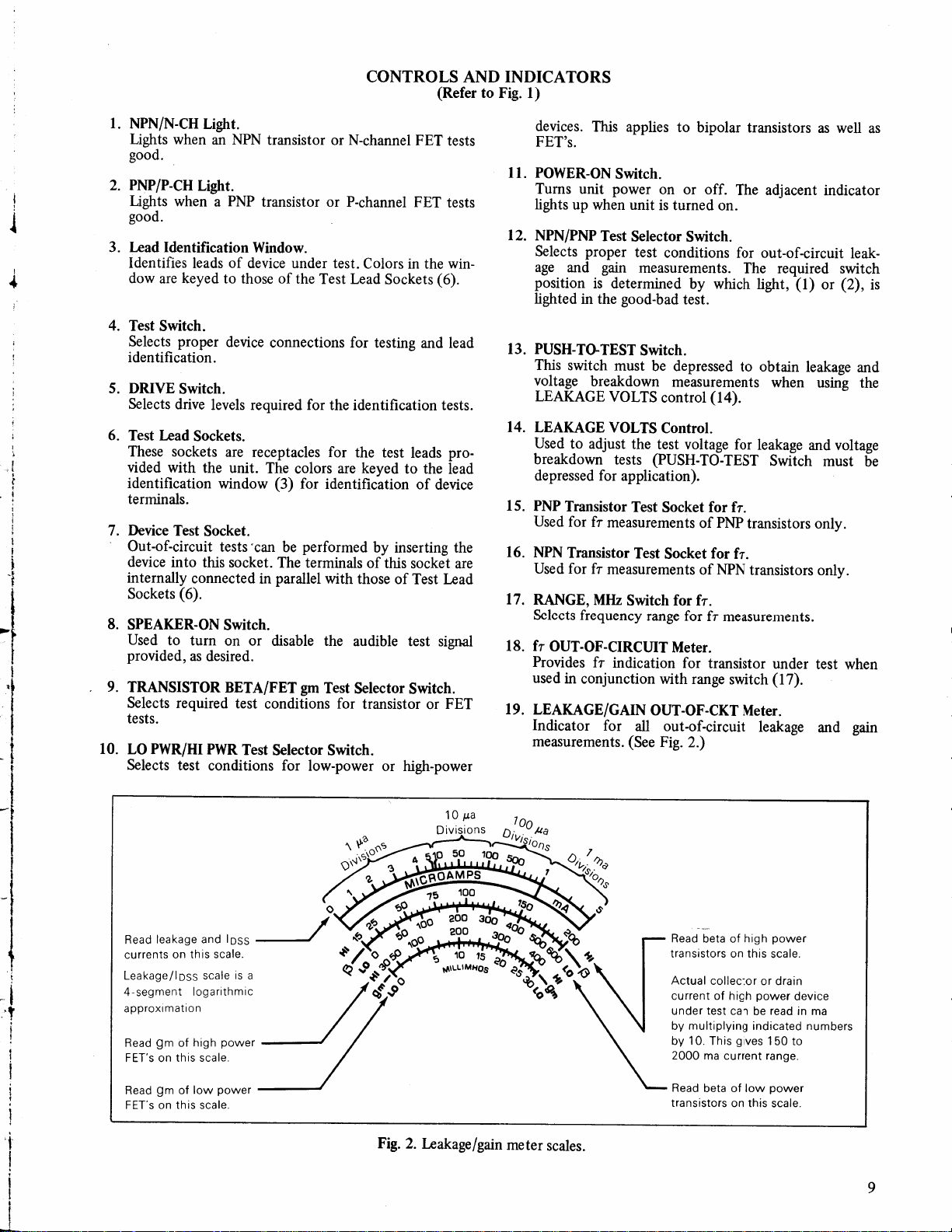
peag
peag
peag
u$
u$
uo s,IlJ
e6eleal
sltll
uo sluolJnc
SSal/aOe)eal
luar.uOas-y
uorleurxordde
'o
q0!q
srql uo s,Ill
'alecs
lo
od
r',lol
stql
'olecs
SSol pue
'alecs
e sr aleos
crurqlrre0ol
rennod
rs^
.tld
.Z
umE/atqerl
retatu
'sel?rs
Aq
Aq
peag
lenlsv
luollnc
Japun
'01
OOOZ
eu
peoU
'o
etaq
q6lq
slolstsuell
srrll uo
q0lLl
lsal
6urAldrtlnu
sentO srql
luollnc
lo
elaq
lo lolcollos
aq uec
Mol
srql uo sJolsrsuell
lo
rennod
'alecs
ureJp
lannod
ur
peol
polecrpur
0g I
ol
'e6ue:
lennod
'ale3s
ocrnap
eur
sraqurnu
Page 10
USING
MODEL 530
THE
I
{
IN-CIRCIIT
Make
TESTING
sure
being tested,
charged.
A. Transistors
1. Set the DRIVE
2. Connect the
the three leads of the device
test leads must
color Test kad Sockets
Move
3.
positions
glows.
Switch
whether the device is
P
channel.
good
will do so in only
"THINGS
(see
this
Test Switch
transistor
Identification
good
positions
IBad Identification Window
the
cally all
BASE
4. If
there is
lamps
moved througlr its six
the device under test
Device
a.
(-uy
b. Device with
Device
c.
"SPECIFICATIONS").
FET
d.
5. Re-test the
transistors
most
adjacent Test
BASE
Window.
then be identified.
If
6.
the device tests
4(d)
above
If
the device
7.
position,
circuit
cedures.
SCR'S:
B.
the DRIVE switch
Set
1.
CAI.]"fION
all
power
is turned
off
in the
circuit
and that all capacitors are dis-
FET's:
and
Switch
three
be
(5)
test
leads
plugged
to the LO
you
into their
position.
(in
any manner) to
wish to test. The
respective
(6).
the Test
Switch
until one of the two red
A tone also will be
(8)
is ON. The lamp that
In LO
TO KNOW
(4)
NPN
drive,
most transistors
one
ABOUT
position,
through
slowly
lamps
(1)
heard if SPEAKER
glows
(l)
or PNP
indicates
(2)
that test
Test
Switch
THE 530").
all the leads of the
can be identified as shown in the I-ead
(LO
or
having
junction
color indicated is
Window
good
no
glows)
as
with high
not function
(3).
HI
drive)
the
FET's
indication
Most FET's
in
same BASE
are
gate
the
(neither
the Test Switch
positions,
of
is one
the
leakage
properly
two
Test Switch
color shown in
will test
(3),
since
symmetrical. The
Iead of the
of the two
(a)
is slowly
in LO drive, then
following:
or very low
in
circuit).
open/shorted elements.
with excessive
that
will
device,
that test
Switch
shown
color
Only the
be true.
could
does not
HI
in
drive,
not test with
using HI
base
good
circuit shunting
LO drive.
drive. In
good
positions
in the kad
lead of the
using HI
test
lemove
drive, then 4(a) or
good
in any Test Switch
the
HI
will do
so in
having the same
Identification
transistor
from the
device
and re-test using OUT-OF-CIRCUIT
(5)
to the
position.
HI
its six
(2),
or
or N oi
position
In
practi-
FET.
gain
(see
drive,
/wo
can
pro-
2. Connect
the tfuee
3. Move
the three
leads of the
the Test Switch
positions until the
position and
position
the
4.
The SCR
b. One
are
a. One
haying
Identification
Lead
is
obtained:
NPN.
PNP,
good
NOTE: indications
IDENTIFICATION:
LEAD
a. The BASE color
Window
tion
NPN lamp
BASE color
Window
tion
(2)
PNP
the SCR
the
circuit
lamp
tests
5.
b. The
If
from
to excessive shunting
procedures.
circuit
Diodes:
C.
l. Set
LEAKAGE
2. Set Test Switch
identification).
3. Set
4. Connect
NPN/PNP Switch
the
to
diode
be
tested.
blue
5. Adjust the LEAKAGE
approximately
panel.
trol
6.
7.
Depress
while
Switch
(Green
While
the
keeping
(a)
to each
identification.)
base
performing
LEAKAGE/GAIN
approximately
be
will
Test Switch
Switch
Test
the shunting
on
position
ihe diode
having
cation
full-scale
heavily
example,
-or
relay
should
re-tested
(
will
giving
under
the collector
Window
readings
shunted
transient
a
solenoid
a
be disconnected
using
(in
leads
test
you
(4)
wish to
slowly
SCR
NPN lamp
PNP lamp
a different
(2)
BASE
Window
following indications
the
if
only
is
the
same BASE
in the
gate
must
not have
shown
(3)
(1) glows.
in the
shown
cathode lead when
is the
glows.
should be
bad, then
and
it
tested again
in-circuit),
VOLTS control
(a)
to top
(12)
yellow
and
(14)
position
to PNP.
test leads across
VOLTS Control
l0 volts, as
indicated on
PUSH-TO-TEST
this switch
while
)
give
the highest
test
(3).
by
depressed,
of
step
Meter
upper
the
6, observe
(19).
full scale
other
the
a lower
effect of
the circuitry.
reading,
is connected
(C)
color
If
both
the diode
low-resistance
The
for one
reading, depending
in the
is either
suppressor
In this case
coil.
from
OUT-OF-CIRCUIT
any manner)
test.
through
(l)
glows
glows
in
as shown in
color
(3).
color.
ldentifica'
kad
when
lead
ldentifica'
kad
removed
(muy
be
using
to zero.
(Green
the
Switch
(13)
rotate
two
results
the
the
positions.
meter
position of
position of
cuthode of
the
test lead
to the
positions
Lead
Identifi'
produce
shorted
circuitry;
across
diode
the diode
the circuit
procedures.
to
its six
in one
another
the
the
subjebt
out'of-
base
the
(1a)
to
con'
and,
lest
on
reading
the
In the
or
for
and
:
:
I
{
I
I
I
{
I
,!
't
J
t
?
#
\
.
a
t0
Page 11
6.JJO
eql
ol
o^u
T I
luel
eq1
luel
spuE{,,
,{q
.euo
enlq
'euol
1sol
e
Euloq
.eJr^ep
'pr3oq
I}un
pcrs,,{qd
InJesn
'slueuod
'pegrluopr
aq;
.uorlrsod
'flaarlcedsar
sr Jolsrsu?Jl
sp?al rel}nue
spu?H,,
elqrssodur
ol
'petset
qloq
.sp?al
(puo4do)
o1
luelllrurelq'iI
ar{} uaUO
palcadsns
eql
arn
'uorlrsod
s1sa1
trua}lrture}ur
V
'euol
roy
'O
ri;
I
-ti
{
'e
.q
'c
:sJolslsuB{
p?g-poog
}oS
lJasul
'(1)
qsr^\
o}ul
'(q)
e^o4
xn
(t)
ro
ro
1sa1
gHI
JI
'alup
'v
'I
.:
i
I
i
l
:
I
I
I
:3uJ1se1
peol
agt
'pooE
6JJO
Jo
euo
spu?q
Jo
lsel
aqt Sullcauuoc
spuol no11a,{ pw
eluq ,{uru
o1
poqleu
IIB
}ceuuoJ
p?el
ru,!\
slq}
oQ
sr
aseq eet ueqrt\
e^ual
aql
requnu
JI
qllA\
uolsrrerd-)
1sel
lepory
srolsrsu?Jl
sr euo}
u?c
IINf,UIJ.dO-INO
er{t
eql
ro
(rauueu
ol
Jreql
oqt
aUa
pooS
spBol 0q}
,t1no1s
:Euurrolog
socr^ep
:Eu11sa1
0€S
uec
B ur
srolsrsrr?r1
Jolsrsu?Jl
s?
qcns
o}
UgXViIdS
ru/I\
rolsrsu?rl
Jo
Surprrrord
9NIISgI
qsag
iIAruO
lceuuoc
or{I
'}sol
lso1,
suorlrsod
plun
'snop '(Z)
sot?crpur srnop
uI
'(Z)
1p,r
eas) uorlrsod
uI
'(.,0€S
Jo
er{l
oqt ur rr \oqs
oa sr eror{l
eq] ueql
oq
'lrncJrc
rarnod)
eqt
oerql eql
a,ulcadsor
y
OT
sIItr
pooE
secnop
Suraq
uuc srolsrsuurl
uearE
oql o1
ouo] olqryn?
sJolsrsu?Jl
oer; eq
'arnluag
xlncvN^C
'uar{I 'prBor{
eq
lsot
qcll,us
euo
ur os op
se (smo1E sduel olrr1
qEnorgl po^oru
ocnop
u1 gJl,r\S
eq uaql
puel
[r/r\
eql
'r{luuorsecc6
InJesn
u ur
speel aefl{l
aq u?J
ol
Taoow
uorJ
reqlle
o}
pasn
lcauuoJ
e
otu pu?
eq uec
'Eurleaq'Eurddel
lu?lsuJ,,
pue
qclp\S
pet?cpur
ploJ
yo Surlooc prdur
ptfrs
(S)
o]
olq rolsrsu?rl
tsel
eorql
Jo
spuel
eq}
spuel
}sol
roloc
(t)
Jo
eql
ouol
osle
\
st (g) r{c}!r\S
'NO
orll
reqleq^\
}soru'elrrp
.,(1uo
SCNIHL,
lsol
rolsrsu?rl
u?J
uorlecrptn
}sol
eq}
slr
xrs
repun
petsel
eql
paqord
aql ol
rolcoiloc
puu
11a1
no,t
Jolcelloc
paEueqrrelw
1r
sr
uer{^\
ro
'lrncrrc
eql ol
paddrlc
aql eqord
uuc no,{
Jo
oprs
eql
{g11uap1
lsel
aql
ISSI
eql
eql 8unue1
pelcalqns
ro
u? ,{q
..furdg
OT
oqt
}sel
Ocnec
lsntu
eq
p?oT
f1no1s
o^u
per
III
eq
eqJ
sr
ocr,rop
$eL
auo
A\ON)I OI
qclrng
0q
uorl?cglluepl pBrI
lsel
ots
q
elorcsrp
'(srolsrsuerl
ur) sp?el
rolsrsu?rl
durel
NaN
srotslsu?rt
aropul1\
Jo
roqlleu)
I{rll^\S
q'suorlrsod
euo $
eq wc
lsourreddn
-r(q-euo
eql
puu'esuq
're11nua
oqt uaq/t\
pu?
u acnpord o1
frusseceu
lr
sI
ueql\
echep
oql otuo
Eururuurer
eql esn osIB
Egoud s-dc
'J'd
-truralu
sp?al
01
qcllr\S
sF{}
snorJ?A o1
uy
'Eurlooc
-lrturelul
ellnb sr
-tuoc
'uorlrsod
10{Jos
fue
no.,{
paEEnld
slo{cos
sg
qEnorql
'sdurul
Jr
pr?eq
1uq1
(t)
IBI{1
qcll/r\s
JnOgV
ge
'uorlrsod
s3
pourluepl
'(g)
er11
(t)
q
O-I
0rl1Jo
)
.e
(f
@)
(g)
@)
sr
V
8lefl
:slsel
}oS
Jo
ec?ld
r{Jlrl,tl
er{t
eculd
isuorl
.e
.q
.c
-Jifi
rols-rsu?rJ
uruE
,{utu)
'(tFc
ecneq
IEC
1?q1
sr ecueC
u
sarrnbar
11
tursn
e
t rolsrsuurl
roJ
pe}?nlB^e
tsel
eqt
IIB
'peurtuapr
palecrpur
O.I
oqt
elupdordde
rolsrsu?r]
alqBIrsAB
aas
pcrs,(qd
roJ
pepuolur
gr
paEuuep
q}r,n
1ou
qlpn
[Lr\
lou
erogaq,tJgaA
ra^\od
es?q
qEyq
reUB
'elup
'uol8urpuq
slsel qcrq
4
pu?
'eleg
(t)
qctpr\S
rolsrsuurl
dNd/NdN
tqBU
lsa1
poo7,{q
IH/U1r\d
UA\d
'uorlrsod
eq ol
or{t roJ
'ssepreEar
pelsel
fiT,i
'pe1s01
,(lpraueE
ro rerrrod-q8p1
er{}
ur
qloq
e8e>1ual qEF{
ro
uoqounJ
palroqs/uado
lset
'Eurpaacord
uofuqruq
e^lrp
poo8
aEulloa
aqt
q
spual
(Zt) r{cll^S
t)
(
to
Eulpuadap
ouJI
rolsrsusrl
selBcrpur
ro]srstruJl
1
;
a
i,",i:lll-';L
?
q
fre,r
w
,{padord
.stuauele
ol
qlp\
'a8u11on
1eq1
Eur.,{ylro^
eq u?c
er?
eql ol
'(O
(Ot) r{cll^S
q
aq1 uo
ropun
'lsel
Jer{leq/y\
relrod-lro1
[r
\
lou
u1
'suollrSod
1
I
s e
uu c
rrrol
-rrc
'a^rrp
qJlqrr\'ad.,{1
'1sa1-og
ecl^ap
raqlJnJ
'u/r\op{?erq
uortrsod
ur
,,{pedord
uorlrsod
aql
ad,{1
sI uorlBruroJul
0q1
1r
sr
-ecrlddu
eq
e'1ceg
e
q
"i"t'?H:
UINI
uorl
.(61)
uleq
6.p,,
eql ul
0s3q
pue.l
o^res
aql
esJeler
e sv
IOpoW
IAC
qcrps
EI{I
(o)
prru
aqt
peag
(d) elaq
elecs
or{} roqtarfr\
go
'.,t1elr1cadsar
sr
Eurpuar
sr areq}
,{ue
'uorl?cgrluepr
oloqu
puu
luecufpu
roloc
uoJsISNwr
eqt
Bleq
;o
uorlrsod
uo4rsod
'IEC
lgc
lsel
?1eq
'(peEuuqc
raqunJ
pF
0€S
sl
ur peurulqo
dols
JI
B
UOJSISNVuT
ruE
eql
pue
elurrdorddu
tuE
eqr ol
Jo
O.I
ual6
Surpuar raq8q
eq1 EunF
um8
'p
JI
eql
l
e
eql
B
UOISISNYUI
egl o^resqo
ureE rolsrsu?rt
(61) relau
IH
U/1d
ro
(Ot)
qctprs
tQnop
aql alou
uortrBcurtuepl
Eurpeor
qctns
ro1ca11oc)
.,p,,
JI
Eurpuer
,uolllsod
ro
Jo
alecs
sr
uo ,{ncerlp
tnoqu
rqt
?laq
er{l eculd ueql
uorlrsod
qcrq^r
s?
uorl?culluepl
nopurll
tgg/vrilg
uE
VIES UOISISNVUI
peurulqo
spuodsarroc
eqJ
'(l)
?leq
reaol
puu
orr^€p ul
luql
os patfrsep
eql
sI
eql
ecr^ap
lgg/vrgg
uE
ocr^ep
sl
'tuE
oql
ISC/VIES
uorslsNvur
er{l uo
UA\d
rlsBe
EurDear
tsoJ,
wq
'(g)
uorysod
uo
}sel
ou
peulBlqo
L..d
vrEg
-ls9d
NIVC/ACVXVSI
ralel4J
OT
IH
ro
Surpuedep
uodn
'uo111sod
at1l
'pe}celos
'alBcs
radord
puel
;o
dels
(t)
qclpts
eql
etu?s
aql ul
pe^I3sqo
oql
ploH
(6)
ut
qcrlr\s
puu
-qo
relau
'(61)
eql ol
radord
r{rll/r\s
sl
oql
Eurpeer
rallrua
-Jelur
eql
'uoll?culluepr
sr
Surpeer
lsel
repun
sl
aql
qll/y\
(6)
ur
qrtrl(s
1!e1
repun
sl
eql uo
po^rosqo
NIVC/gCVXVAT
II
j
Page 12
(19).
meter
fr Tests:
3.
Measurement
transistors
A detailed
provided in the appendix
of the
is
complex
explanation
parameters of bipolar
fr
theory and
in
of
of this manual.
performance.
fr measurements
position
uppermost
position
Switch
cation
Connections
provided
is
Socket
indicated
required,
for
position
for
positions
[rad
in
can
the device
or
(7).
The
an
by
"NC"
is
have
ldentification
be
"X".
entered.
I and
Both
2.
the
made
can
required
Where no connection
the adjacent
of
green
base
Window
the
to
inserted
be
connections
these
identifi-
test
into
Test
(3).
leads
Test
are
is
When
measuring
some transistors.
with
may occur
and the G500
is
always
numerical
the 0-500 rimge
To obtain reliable
a.
frequency characteristics
under test, the
of the device
previous
the
Insert
b.
appropriate
transistor leads must
socket
be made
the three-lead
connections
additional
the accuracy
three-lead adapter
absolutely necessary.
the fr
Set
c.
1500 range
0meter
If the reading
d.
the transistor
of
fr, it is
on two
the range
value
lead designations.
(18)
ranges, such
MHz ranges.
reading
(in
this
applies).
lead identification
must
tests.
the transistor under
test socket
fr
to fit into
adapter
the
to
lead length
of
RANGE
and read
the
on
greater
is
under
important to
the same meter deflection
The fr of the transistor
that
example,
information
known
be
properly
If
the socket
provided to
transistor.
can be detrimental
this test; therefore,
should be
MHz Switch
the
MHz
1500
than 300, this is the
test.
know that,
as the 0-100
gives
the highest
the reading on
regarding
of the
(15)
the device
transistor
polarity
and
as determined
into the
test
(16).
or
match
cannot
provided,
make
Note that any
used only
(17)
to the
value on the fr
scale.
MHz
the
The
the
use
the
to
the
in
i
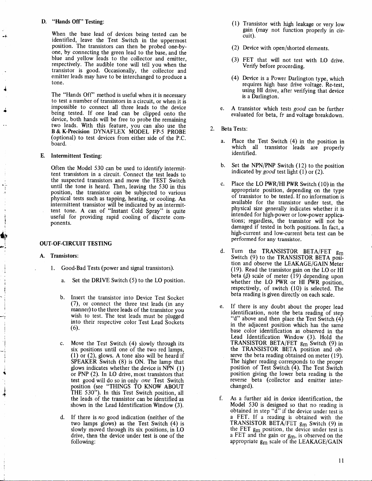
NUMBER
LEAD COLOR
TEST
(3)
Yellow
Device
Tests
BVCES,
BVCEO,
ICpS
ICEO
BVCBO,tCgO
BVCpS
4.
With Base
a.
b.
c.
IgCS
Ip,CO
Ig,gO
BVECS,
BVECO,
BVEBO,
if
fr
Emitter
X
X
NC
X
X
X
(Collector-Emitter
Shorted
Connect
into the
Make
position.
Move the
which
dicated by
transistor
test socket
the DRIVE
sure
Test Switch
produces a
the
AND
(2)
Green
Base
X
NC
X
X
NC
X
to Emitter):
to the
(7).
switch
good
polarity
lights
(l)
Blue
Collector
X
X
X
X
X
NC
Breakdown
test leads or
(5)
is in the
(4)
to the
indication,
(l)
or
(2).
Test
Switch
Position
I
I
I
2
2
2
Voltage
plug
LO
position
in-
as
it
1
!
I
{
I
l
e. If the observed
the RANGE,
and observe
range
reading
transistor
If
f .
the observed
RANGE,
and observe
the transistor
of
readings
If
E.
All
eliminate the
identification
when the device lead
the following
required for
positions
there
ranges
absolute
NOTE
voltage and
of
MHz
greater than
is
under
MHz
meter
below 5 on
is a difference
the scales
where
value for
ON
BREAKDOWN
breakdown
need to
when
beginning
table
the
device
Test Switch
less than 300, set
reading
test.
reading
switch
under
VOLTAGE AND
identification
indicates
is
switch
(18).
fr is the
know
(4)
(17)
the
meter
50,
this
is less than
(17)
to the
This
test. The accuracy
range is
this
in readings
overlap,
most accurate.
TESTS
tests outlined here
the device lead
test.
the
the connections
tests. The indicated
correspond
to the 0'500
(18).
If
the
is the fr of
0-100 range
is the fr reading
questionable.
the
In
is known,
to the
the
50, set the
of
on two
largest
cases
good-bad
If the
good
rn a
of
identified
test
to about
and move
positions which
the lowest
GAIN
transistor
d. Set
e. Set
indication
Test Switch
by observations
as follows:
o
Set the
10 volts.
o
Depress
the Test
r
Test Switch
The
indicated
(19)
Meter
leads can
the NPN/PM
corresponding
which lights.
the LEAKAGE
zero.
NOTE
paragraph
of
test
in two adjacent
(4),
the collector
LEAKAGE
PUSH-TO-TEST
the
gave a
is
VOLTS
Switch
be identified.
(4)
good
(4)
position
current
position in.which
the
Switch
to the
"A-1"
results
positions
can
during
indication.
VOLTS Control
the leakage
Control
Switch
between
LEAKAGE/
on
(12)
polarity
the
which
to
light
(14)
(13)
two
gives
the
(1)
be
all
position
(2)
or
(l
to
)
t2
Page 13
l
'S
snIJ
'e
'q
't
'p
i
I
I
:
-rd
'a
l
gilAt
'B
I
I
I
i
I
5
.L
'q
'c
OlIJ1
IoJl
ra1a61
st
\
qll
er{t
ecl^ep
S3J1
peporls
'e8u11ol
:s/t\olloJ
e^e{
eq1 u1
aql
aql
Jt
1ICV
tos
aql
lsol
e8e
t{}t1\
peleo
aq1
OlIJng
reUV
qct1lrrs
Jr
p?ol
}o{cos
les
,(1nop
Iorl
aEueqc
NIVC
aq1
:(uod6
ssardaq
aqt
e
plun
tuorrnc
sr
'(61)
aql
uB roC
}ceuuoJ
u
rolcalloc
Jopun
pelceuuoc
]uerrnc
sr
u
JI
lsel
snonard
{1uo
eql
'perrnber
lsel lcexo
acuepedur
aq] sserdaq
eql
pourJads
}ceuuocsrq
e{r
'posserd
uo
S!IJ1
:(uadg osu_g
(t)
ur
ossq eq}
'p?ol
os
pu? p?ol
(D
aqt sserdeq
(y1)
ur
ralaur
leuud
q
eqt oseercw ,tprols
druqs
es?q oql
lcuxe
pw
oo
'lse}
oql rag?
rallltuE-Io1ca1o3)
:(ra11nug ol
paglcads
senle^ esaq]
(l)
qcrprs
snoherd
'lsel
'lsol
lauud
lorluoJ SJ.IOA
sr aEellol
Jo
slBur(urel Jolcelloc
lsol
ar{l
Jo
enlu^
aqt Sululuuelep
roq}lo
'palceuuoJ
Ewlresur
l?ql
os
er? sp?el JolJelloc
saop
poal paicauuolun
gCVXVg"I
egl aseercur
plun
luorrnc
sr
'(61)
eqt
re]lrug'ro1ca1o3)
ISEI-OI-HS1d
ECV)VE-I
eseoJcur
uo
pe^Iesqo
aEu11o,r oql
rollrue-rolcoiloc
01 peuoqs
lou
eft
aluunxordds ue
'aEu11o,r
luetuaJns?atu luarrnc
,{q
oql
rcu
oql
OEJng
petuorpur
eql
Jo
lueruernseoru
acuepadtul-r{EFl
rallnue
aEulloA
luerrnJ
lu lpu[
u
'umom1
tsat
eqt ul
eJ? suorlceuuoJ Jolsrswr}
e3e11ol
Jo
uorlurqrpc
(p1)
oq u?c
'parrsap
oql ol releullo^
achap eql
ISgI-OI-HS1d
gr
're1aru11ol
IIrl\
eq
UI
ISiII-OI-HS1d
eEqeal eql o^resqo
NIVC/ACVXV1I'I
ralau
ocnop er{l
ropun
redord
,,7,,rqdvtflurud
'aloqe
eqt ,(po
ag'polceuuoc
qJnoi
1or1uof, SJTO1
ISgI-OI-HS1d
uo
pe^resqo
eEe11o^
'onTB^
tuorrnJ
(€1)
uo11nq
uo
rellrue
sr,ql
sl?ur.urel
0q1 o^?el
aql
loeuuoc
repun
uo11ng
IortuoJ SI'IOA ECV11Vg'I
'pasn
luerrno
'(61)
'lsol
u/y\op{?org ret}nug-ro1cago3)
uorysod
Eurlcauuocsp
ur rolsrsuurl
atns
aql
(p1)
gllA\
puu
SJTO1
-uo3
a8ueqc ueppns ro
ur
NIVC/ECV)VS'I
lauud
oqt
aEelloir u^\op{Barq
'(."n9)
't_p^tJlon.
ssoJcu rolatullol
Jo
el{l
roletullo^
'lueuernseau
eseg
qll1\
]se]
pourcods
sE
peecord
uorlrsod
pesn
sB auES ar{}
ur
sr
uor]Btrpur
,XVST
JI
er{}
'pesn
p
-qEfq
rellnuo
pu?
'lsel
(81)
pw
(tI)
ol
eql
reu?
oq} esr^\rer{}o ilas uaaq seq eEu11o^
-{Bel
'JOJre
(et) uolnq
-ap
sB
-rpur
st
s1ql
eEellon
Jo
lsol
lceuuocsrp
lsel
eql
eseq er{l Eurpuaq ,tq ro
lsel
eql
rallnue
pu?
lotu
aw
'1aund
ot
'olez
(t1) uo11nq
pue
SIIOA 1ICV)VgT
-uoc
uappns ro osuercur dreqs e
/gCVXVgT
uo
pet?crpur
esug
sFII
'e
'q
'c
'p
'e
l
'8
'e
'q
'c
'6
OBJI
sruJ
'q
JJ
'e3u11orr
:S1Y\olloJ
e^Bal
eql ul
aql
aql
31
louxe
les
etll
tsel
a8e
'passard
'lsel
OUJnI
Jennuir
qclprs
ro
'o1
ta{cos
las
er{t
'otez
sserdaq
Iorl
aEueqc
NIVC
eql
luerrnc
JI
.a8e11ol
:s^rolloJ
e^?e.I
oq1 ur
eqJ
oql
JI
ECV
luerrnc
B sr
tsel
snonard
snonard
aq1
'parrnbar
SI'IO1 ACV
1sel
ecuupadurr
rolceiloc
aql ssardeq
1se1
pagrcads
lcouuocsrq
eql
oW r{}tA\
uo
petecrpur
eql sr sn{I
:(uado
ilesul
er{l
(l)
os
erB spsel
aq1
lllun
(tt)
ur
ralau
laued
er{} sl
os?B-ro1ce11o3)
B sr
tsel
snorlard
snonerd
uu ,(Iuo
eql
'parrnbor
1se1 lcuxe
Jo
slBrrture}
pagrceds
senpl asaql
(t)
qctpns
.lsel
'lsa1
lauud
lorluor
aEellorr
sr
Jo
slBurrure}
'a8u11o,r
ueaq suq a8u11o^
el:esqo
enIB^
O!IJ1
eq1
Eunnutrelop reUV
tprl}
{po
'pelceuuoc
ACV)VE.I
oql esBercur ,,{1mo1s
luorrnJ
sr
'(61)
OBhg
pegrceds
senpl oseql
ere
(l)
qclprs
'lsol
'lsel
leuud
lorluoc SI'IOA
sr aEellol
l?
ilurll
u
oJc
q
eleurxordde uu ,{po
(71)
'relaurllol
llas
luotueJnseoru luarrnc
ISEI-OI-HSnd
rqdvtterud ur (t)
aq1
luerrnJ
(p1)
'urnou4
1sa1
oq1
suorlceuuoc JolsrsuBJl
Jo
eql ul
er{l eJB
aEellol
Jo
uorlurqrpc
oq
u?r
'parrsep
oql ol relaullo^
ecr^ap 0r{}
ISgI-OI-HS1d
;t
'pasn
[Lr\
eq
ul
uounq
eEu>1ua1 or{l
NIVC/iICVXVE'I
radord
,,7,,
Jepun JolsrsrrsJl
ISgI-OI-HS1d
gcv)vgT
uo
pa^resqo
eEullol eql
.enIB^
1B llru11
e
'umou4
tsel
aEellorr eluuxordde
Jo
uort?rqrl?c
eq
wc
'parrsap
os?q oql ol rolotullo^ acuepedur
ropun ecr^ep 0r{}
']sel
peurJads
uortrsod
I
eql
JI
'pesn
lceuuoc
e
rellnue
ropun
(€1)
uo11nq
Iorluoc sI'IoA llcvxvET
relJu
eq} esLt\reqlo
'JoJJo
t)
(E
luorJnc
releu
ocr^ep eqt
Jo
uorlrsod
'aloqu
1s0l
olur
rotcalloc
puu
Iortuor SJ-IOA
(tI)
(€1)
uo11nq
sJTon
ro esuarcur dreqs B
pat?crpur
pogrcads
peocord
uonrsod
e|'uss 0rl1 eJ? suorl"OuuoJ rolsrsuBrl
uorlucrpur
eql
lceuuoc
?
prru
lsel
sB
peocoJd
posn
s? er.uBs
uI
sI uorl?crpur
-XVE
eql
-q8q
puu
'}se]
pu?
eql 01
eql
-{uel
-ep
sB
'(61)
rapun
r{1l1\ aEello1 u^\op{BeIg esug'ro1ca11o3l
lsol
lcauuoJ
lsel
oseq
ol
pu?
-uoc
ueppns
/SCVXVET
uo
:(uadgrolgurg qll1(
lsel
sB
pesn
w s?
sr
-XVin
eqlJI'posn
-q8fq
roloelloo
€I
Page 14
Depress
d.
set the LEAKAGE VOLTS
specified
PUSH-TO-TEST
the
test voltage.
button
control
(13)
(14)
and
to the
e.
Disconnect the voltmeter, if used, after the
test
voltage has been
age
current
measurement will
set; otherwise the
in error.
be
leak-
Disconnect
test voltage
age current
With'the
f.
pressed,
indicated on
This
test.
10. BVB3O
With
Collector
a.
Set the LEAKAGE VOLTS
zeto,
Set the
b.
adjacent
paragraph
indication
Disconnect
c.
connecting
bending the
transistor
emitter
Depress
d.
adjust the
until a
current is
meter
device
measured accurately
impedance voltmeter
emitter
not leave the
voltage is
the voltmeter, if used, after the
been set; otherwise the leak-
has
measurement
PUSH-TO-TEST
observe
LEAKAGE/GAIN meter
1699
is the
(Reverse
Emitter-Base
Open):
Test Switch
to that
"2"
which
in kad Identification
the
collector lead, either
the test lead if
collector lead and
in Test Socket
and base leads are
the PUSH-TO-TEST
LEAKAGE VOLTS
increase
sharp
observed on LEAKAGE/GAIN
(19).
This is
under test. This voltage
terminals of the
voltmeter
adjusted.
will
the leakage
value of the device
Breakdown
(4)
used for the BV6'ps
has the
so
(7)
connected.
or
the BVegO voltage
by
connecting a
across the
device under test.
connected after the
in error.
be
button
sudden change in
(13)
de-
current
Control
to
the
sarne*Firr
Window
connected, or by
inserting the
so that
switch
Control
as
(19).
under
Voltage
(la)
to
position
test of
color
(3).
by
dis-
the
only
(13)
and
(14)
of the
can be
high-
base and
Do
With
pressed,
dicated
is
the
12. BVBCO
Volfage With
a. Set
zeto.
Set the Test Switch
b.
adjacent to
paiagfaph
indication in I-ead Identification Window
Disconnect the
c.
necting the test lead if so
bending the base
sistor in Test Socket
emitter and
Depress the
adjust the LEAKAGE VOLTS
until
current is observed on LEAKAGE/GAIN
meter
device under test. This voltage
measured accurately
impedance
emitter terminals of the
not
voltage
I3CO
13.
Base
Open):
PUSH-TO-TEST
the
observe
LEAKAGE/GAIN meter
on
IpgO
value of
(Reverse
Base Open):
LEAKAGE VOLTS
the
that
"2"
which has the same-Fise
collector
PUSH-TO-TEST
a sharp
(19).
leave the
is adjusted.
(Reverse
increase or
This is the BVECO voltage
voltmeter across the
voltmeter
Emitter-Collector
the leakage current as
the
button
device under
Emitter-Collector
(13)
(19).
test.
Breakdown
Control
(4)
to the
used for the BV6'pg test
lead, either
base
lead
connected, or by
and inserting the tran-
(7)
so that
leads are
switch
sudden change in
by connecting a
device
connected
position
by discon-
only
connected.
(13)
control
can be
collector and
under test. Do
after
Current
de-
This
(14)
color
and
(14)
of
high-
With
in-
to
of
(3).
the
the
the
l4
(Reverse
IBgg
11.
tor
Open):
This
current
voltage.
follows:
a. Leave
in the
The transistor
b.
the
If
c.
required, the
AGE VOLTS
exact test
impedance voltmeter
base
d. Depress the
set the
specified
Emitter-Base
is
a specified limit at a
If
these values are known,
Test Switch
previous
previous
only an approximate voltage indication
terminals
LEAKAGE VOLTS
test.
connections
test.
panel
control
voltage is desired, connect a high-
of the device
PUSH-TO-TEST
test voltage.
Current With Collec-
specified test
proceed
(4)
in
the
calibration of the LEAK-
(14)
to the emitter and
position
test
are the
can
under test.
control
same as in
be used.
button
(14)
(13)
to the
used
If the
as
is
and
This
current is a specified limit
voltage. If
follows:
Leave
a.
in
The
b.
the
If
required,
AGE VOLTS
exact test
impedance
collector terminals
Depress
d.
set the
specified test voltage.
e.
Disconnect
test
age
these values
Test
Switch
previous
the
transistor
previous
only
voltage
current measurement
test.
an approximate voltage
the panel
control
voltage is
voltmeter to
PUSH-TO-TEST
the
LEAKAGE VOLTS
the voltmeter,
has
at a specified
arc known,
(a)
in the
test.
connections are
calibration of the LEAK-
of the
been
test
the same as in
(14)
can be used.
desired, connect a
the emitter
device under test.
button
control
used, after the
if
set;
otherwise the leak-
will
in error.
be
proceed
position
indication
(13)
(14)
used
If
high-
to the
test
as
is
the
and
and
Page 15
arlr
qqA;J
'pesserd
uo
pelecrp
sl
eql
.e
.q
SJllng
\
a8ullon
qtl
las
eqt
'orez
tes
er{t
luecufp?
I
.Vl
,,
I
I
)
.
.c
.p
lsnfpu
Irlun
Ietetu
ecr^ep
lou
e8u11o,r
e
luerrnc
rellnuo
anle^
OJII1
asranag)
osug
}sel
]sq1
o1
,,7,,
qdetaeJf.;d
ul uorl?crpur
lrT*:#Lj
aql ssardeq
or{t
sr
.(6I)
repun
perns?oru
ecuepadurr
e^Bel
sr
sl?urturel
eq]
p?a-l
sl sFII
'palsnfpe
JSEI-OI-HSpd
eql elJesqo
Jo
eql
01
peuor{S
ECVXViI-I
(l)
qcq/r\S
roJ pesn
s?q
qcF{rt\
gCV)VE.I
os?ercur druqs
uo
pe^resqo
eql
'lsel
flalernccu
,{q
Jolorullo^
Jo
ew
r01etu1[o^
a8u>1ua1
NIVC/ECVXVg"I
ecr^op
SITOA
eql
eql
aql ", f3il3"T,",t
ISgI-OI-HS1d
Ocr^Op
t)
(e
uopnq
relau
repun
rotrelioJ-ropnuA
:(ro1ca11o3
ar{t ot
uorl?rulluepl
lser
qcly'rs
SI'IO1
ueppns ro
sJcng
eEu11gl._slqJ
eql ssorJe
repun
-op
lueJJnc
s?
-ur
stqJ
'(61)
'1sel
IoItuoJ
(tI)
lsel
scJng
eSPq^eIu?S
lropurlA
spuer
(tI)
lorluoc
a8uuqc
Jo
eaullor
u Sullcauuoc
'lsel
'g
.l
u^\op{?arg
ot
uoyllsod
Jo
Joloc
'(E)
Bnld ro
puu
(71)
ur
NIyC/ECy)VET
eql
eq uec^
-qaq
puu rolJolloc
oo
aq] relJ? pelcouuoc
'7
:S.IEC
'e
'q
'c
'p
'e
JI
V
tuE
tsal
pug-pooC
tes
aql
lceuuoJ
ru,!\
}q3[
U1I)VEdS
s.IgC-f
lsel
ESVg
ESVS
eql
uorl
ou
lgc
rapun
IEC
pelunlu^e
eJoJeg
,{1Fu1od
11)
srUEI
:slseJ
fi
i
:t^:t
reaod)
ruC
eql
(q)
sta{cos p?e.l
tsel
e^ou ,(pro1g
setecrpul gtg
u
B
puu
qclvrts
illr\
lsot{)
'roloc
(t)
s!
/Y\opurA,\
lsel
sr
qcq^\
se
s?q
uaeq
to
.(Z)
J
:,XT
IUUBIS
pu?
(g)
r{clr^\s gn
ecl^ep
eql ol
lrosur
ro
pooE
(g)
e]BJrpur
uorlrsod qcllr\s
aqt
slsat
'Surpaacord
ur
(l)
qclprs
'IEC
il1lrr
ouol
st
'NO
poo8
s.IEg-f
aql
u^\oqs rolor
ur
'a1n7
sr
uorl?Jrpur pooE
'e^rlcaJep
pooS
aql ul
petucrpu
e>[?tu
peurure}ep
i?j?yr,:l
;
"
aql ot
lsal
lse;
[tun
duel
eq
o&r1 uI
are
p?{
'panrecar
s?
od'
11 rs
:(s.JEC
IH
spsel
lelcoS
eql
(1)
to
JI
preer{
eql e^Br.l rl3lq,tl
eq u?c
3urno11o3
eql eJns
uo
'uorlrsod
lsel 1?
'(l)
Ieporu
(Z)
al{l
luecefpu
ar.u?s
'(pculauru,ts
-Bcurtuopl
eqt ueql
reqpnJ
'sdals
acrlop
{q pelecryw
r{cl,{^,
tes
eculd
Jo
azn
roJ
i;Hfij
tuE
uorlcunf
esre^or puB
]noqll
flluaueurrad
.papoeJxe
op
,ed.,{1
Eurrnoloy
pegrluepr
pu?
t$i
erl]
,{1Fe1od
eql
,lnrr*do'iain
JEC
alqupz,ru
,ssalpruEer
ur palsel
rqt pn.g
epcs
s.IEg
.e8etu?p
oI
,(lelrysod
lou
.slsel
tii tttr
1
.g
SJIII
eseg
srql
'a8u11ol
:s^\olloJ
.v
.q
JI
.c
.p
ros
.o
lsol
e3e
J
sl
]uerrnc
Jl
3H#
,(tuo
operrnbar
ACV
lcuxo
rolcailoc
eql
pagrcads
ovr qll/tt
,passard
potecrp
oqt
esre,rag)
o] pepoqs
B sr
esoqtr
uu
aqt
SJTOA
lsel
ecuepedurr
slBurturel
aql sserdeq
EOVXVgT
1so1
lceuuocsn
aril
eEu11o^
suq
luarrnc
uo
SJ!I1
Jo
onIB^
:(ro1ca11o3
rotrolloJ-roprug
]Full
pegrceds
sonp^
(rfiXiffiT,Ti
laued
lorluoo
sr e8u11oa
reloullo^
Jo
'e8u11ol
ueaq
l?
e
eJB
1sa1
oql
q
suorlcouu;Tiilil,Ht'itril3
e,n
eluuxordde
eql
]uotueJns?eru
e8ullol
uorlerqrlBc
(p1)
'perrsep
of
oql
ecnep
JSAJ-OI-HS1d
sJToA
gr
'ra1eu11ol
iles
[Lr\
aq
rsar-or-Hsnd
e{t elJosqo
aEu4uel
NIVC/gC\1XV1IT
eql
ecr^ep
tuarrnJ
'unou4
eql
Jo
eql
eq uuc
lceuuoc
?
rellrue
repun
lorluor
(71)
'pesn
asl&\rorllo
eql
UI
'JOJJa
luaJJnc
relotu
'(6I)
repun
'lsol
tltl1\
lsol
paurceds
su poecold
uorrrsod
pesn
s? a.,,?s
ur
sr uorl?crpur
-XVIIT
eqlJI'posn
-qEg
pqu
'1s01
(t1) uo11nq
pu?
ol
eql
eql
ratJu
-ryel
(Et) uoltnq
'ep
sB
-ur
sgql
'q
.c
.p
.o
\
ere
lou
si
SOlt
Tt. ;Yl
dNd/NdN
O.I
ol
eq
oq} i6y
.{lpreuaE
ralrrod-.lgF{
eql
qt;d
eq uuc
Jr
pa8uurup
peecxo
erar{A{
lsel
rart
g,r
(zt) qctp[s
(t)
t9
U/t\d
Euryuedep
ou
repun
'lsat
lr
ror{leq^\
rarrrod-noI
lou
eq
uJ
rser
*a
or
tq8n
{q pelecrpur
IH/UA\d
.uorlrsod
J-l
.pelsol
IgC
satucrpur
to
il1,!\.
ecpep
.suorlrsod
rurr'r*.E-c^iffi'q
rEg/vrfi'X';i#3^#ff:ii.1,1''l
JAf
rqiroi,itF
s?
pourluapr
oql
sr Blup
1
p.
uo
NIVO/aOV)VE'I;o
NOI.INVJ
uo^rJp
olur
,tq uiy\op>leorq
eql
s.IEd ggyg
u^\opluerq'
e8uurup pro^u
s o1
e
0I
sllo^
ur
sr ecr^ep
'elqslTp^e
s? s r r',
o
eqt
tatau
lepory
'ralamoq
IEC
,(ue
eqt
eql
'(7)
(Ot) qcrprs
uo
aq1
eql
sr
e
'1ce1
eq u'c
uB
'(6t)
uorlJnpuoc
'0tS
uor
eq
saEellol
r{cF{^\
ad.(1 uorlJunf
ro
3_o
aqt
,{gadord
eJl^o_p
r p eu rrr n
u
ocl^ep
eql q
ad,{1
sr_ uorl?ruroJql
pcrs,{qd
pepuolq
isuorlecrlddu
JJ
poderuup
-Uaq
-rqd
rrclr^\s
aluudordd?
SI
Page 16

3. IpSS
Current:
Currents
l0 volts;
up
the
microamps
the Ip55
values
to 5
current
when
milliamps
testing
for
drain-to-source.voltages
values
obtained
considered
characteristic
Fig.
(Sqf.
full-scale
considerably
reading
value
is
geater
is
measured
between
accurate
usually is
3). Most power
readings
higher
obtained
than 5
accurately
can
be
indication
above
10 volts.
many J-FET's
above
l0 volts,
5
and l0
because
the
constant
FET's
because
than 5
the IpSS
milliamps. If
below 5 volts,
milliamps
with
the Model
measured
is
limited
Although
are
specified
the Ip55
volts
drain
above
a few
will
values
a
full-scale
the
actual IOSS
and
cannot
530.
below
to 100
at
cariSe
current
volts
provide
are
be
microamperes
some cases
FET
4.
Gate
to-Gate lrakage.
Note
a.
in the GOOD test.
b. Set
polarity
Set LEAKAGE
c.
volts,
age,
to several
will be
l-eakage:
the
Drain-to-Gate and/or Source-
polarity
the NPN/PNP
that indicated in
of
VOLTS Adjust
approximately,
if known.
milliamperes,
limited
to 5 mA.
indicated by
(12)
Switch
(a).
or the desired
lights
to the
(14)
and in
(1)
(2)
or
opposite
l0
to
test volt-
I
I
a
s
F3
z
Llj
(E
E
l
=.
-il
G
o
I
Fig. 3.
a.
b.
c.
e.
f.
'cs=0
/
l,/
t/
It
a
f,
17
I
I
7
246810
Vs5-
DRAIN SOURCE
Typical
Set
zeto.
Move Test
produces a good
Set the NPN/PNP switch
indicated by GOOD
Depress the
Increase LEAKAGE
observe LEAKAGE/GAIN meter
exceed
parameters
meter can be connected
source of
the exact voltage corresponding
served
rent exceeds 5
exceeds 100
panel
cause of
The LEAIGGE/GAIN meter
IpSS.
depletion
mode
the LEAKAGE
Switch
(4)
indication.
test lights
PUSH-TO-TEST
VOLTS
volts unless
10
known. A
are
the
device
IOSS
reading. Once
milliamps
microamps
voltage calibration does
the
IpSS
built-in
of
current limiting circuitry.
FET's
T--------
(VOLTS)
VOLTAGE
FET
VOLTS
to a
(12)
button
FET
the
high-impedance
across the drain
test to
under
the observed cur-
below
above l0 volts, the
range from
can
I
V
I
-0
2v
-0
4v
I
-0
6v
i
-0
8v
I
10V
I
-r
,y
-------
t4v
I
characteristics.
or
(14)
which
position
(2).
control
position
to the
(l)
(13).
(14)
control
(19).
type and
and
Do not
test
volt-
and
determine
to an ob-
10 volts or
not
apply be-
(19)
will read
a few
to
d. Depress the
(13)
six
meter
will
Test Switch
FET
5.
(Junction
a. With the
inserted in
Switch
Switch
La*p
Note
b.
Identification
connection
c.
Set LEAKAGE
d.
Set the
polarity
e. Pqsition
associated with
the
Window
f.
Depress
slowly
(14)
until a sudden
indicated on LEAKAGE/GAIN
The
have
FET's:
MOS-FET:
Depletion
6.
PUSH-TO-TEST
and move
positions
(19).
the Test Switch
and watch
If
the device
indicate zero current
positions.
Drain-to-Gate
or Source-to-Gate
Diodes):
FET connected
test socket
(5)
in
(4)
until
(2)
(l)
or
the base
position
HI
the
good
a
will light.
which appears
color
Window
gate
to the
VOLTS
NPN/PNP
indicated
the
Test
switch
by lights
Switch
the
collector lead
in the
(3).
the PUSH-TO-TEST
adjust the
starting
LEAKAGE VOLTS
zero
at
increase
current and the
following
the
J-FET:
Forward
for
meaning for
gate-to-channel
the
tion.
The Breakdown
combined
channel
leakage
protection
device.
Mode
FET's
(low-power):
button
(4)
switch
through all
LEAKAGE/GAIN
good,
is
in two
the meter
the six
of
Leakage
place
leads or
DRIVE
to the test
(7)
and operate
indication
is obtained.
in the
(3).
This identifies
FET under test.
of the
(12)
to
(l)
or
so that the
lead
is
Lead
ldentification
switch
(14)
to z.ero.
match the.
(2).
indicated
(13)
control
(4)
gate
control
gradually
and
in
leakage
increasing
current is
meter
corresponding voltage
two
types of
bias
current
and
voltage
P-N
voltage for
of
currents
the
gate-to-
current and the
diode
if present on
,
Test
l*ad
the
color
as
and
(19).
junc-
the
t6
Page 17

;o
louuuc
sF{}
eplt\
se eol
alu8 eql
opon
epou
srolstsuerl
eq
'stlo^
ontq aql
ogr sserdaq
lsel
1ISVB
Eurpear opcs
apop
roloc
pBrI
ontq or{1
eql
qctyos
p?ol
dNd/NdN
'sllo^
uI
aql suoylrsod
sr
B
peleclpw
o} spuodserroc
eql
roJ plorlserr{l
aEulual
eq
sarpber
eq]
aEqeel
er{J :uorlBcurluepl
'peurluepr
AIIuvTod
gCVITOA
pue
(t)
qrllhrs
uo
apoqpr
pal?cryur
epop
oql ol (t)
qcllr\S
ISAI-OI-HS1d
(t)
qcll/ils
eseq aerE) suorlrsod
Jo
ouo
pal?clpu
're/l\ol
(t)
qcll/hs
ralou
or{}
'epop
pernsuatu
acnep
'sluarrnc
qcurd pm
qderEered)
apouB
^\oilef
ol
il
uortBculluapl
/l\ollef pue
Iopun
'(uorluclpul
(Zt)
MVC/ACV)IVAT
eq}
q
flqrnt,
teql
1cafqns
sr areg acuepadul alu8
'ggo
psg-poo3) s.IgC
eq wc s.Iac
pelsel
'(..1-V,,
puB
qclp\s
lolluoc ISnf11V
lsel
ISSI-OJ-HS1d
0r{l s?
]sel
'lsel
tsourreddn
[oltuoc SJTOA 1ICVXVgT
eqt
ueo^ueq
'(uorlucrpur
relou
}sal
o^U
luerrno
sl
lsol
oql
orczro rumuruFu er{} ;Sfp
SI.IOA 1ICVXV1IT
lorluoc
es?eJcur ueppns
Euppear
u \op>l?orq
,tuy
ecrnos-ol-u1prq
s.IgC epou
lepow
aqt
aluE
dn>1crd
Euunssu
l
'L
I
'I
'(,
etu?s
:sePolo
pErI
Jo
eql
'E
'q
'c
'p
'e
'q
'c
'p
'o
l
'E
'q
les
tes
1s0]
tos
tes
1sa1
eql
er{t
I
I
I
t
'f,
f
s?
'0€S
pos?Iq-asre^ar
puel
ro/puu
,(1auerlxe
qEq
teql
tueuecu?qug
lueuacu?quE
se
fu,r
u?c epop
eqr
'uorlrsod
aql
s
lnoqB
lcouuoJ
apop
'sp30l
er{} alotu
uaart o/hl
eqJ,
.(6I)
p?e[
eq1 u1(c)
:eEe4er1
}ceuuoS
Jo
spue
o/hl
tsel les
asuq
uaerE)
'uorlrsod
eW
s
lnogB
sserdeq
1se1
olurado
e^rasqo
luql
elou
lr
rer{lo
lsel
e^?rl
i:iiX
lsnlpv
lrlun
esp\
uorlaldap ralrod-lro1
aql ,{q
eq ew? oql
tutlceuuocstp .,(lerepi'Euqsal
ferls o1
eql
qlF\ pu?
fe,r
ou
qEg
go
:(1seg
eql
uI
epoqlBc
sp?el
dNd
eql ol
(?I)
or
eqt ot spuel
qcll^\S
'(et)
Jo
egt
re^oqcnr \
secnpord suorlsod
ue
-dn
NM/ACy;1V1IT
releu
oql ol
pelcauuor
uoISa"ITOJ
'(E),noput^l
eql ot sp?o[
uo4rsod
dNd
etlr ol
(tI)
o1
(et) uollnq
puu
reddn
on1
(0t)
pu?
I{Jlt/y\s
ul
pue
uorlrsod
uo Ewpee r
(71)
-{colc
ur eEueqc ro
sFII
'srncco
luerrnc
aEe11o,r
-?crput
'o
'I
'Z
'II
.I
'7,
.E
pBrI
'e
'q
'p
'0
nusz
'B
'q
\
'p
:s.uJs
tos
eqt
e^ory
oql
uorl
aql
epoTp
:sapol( $uez
lceuuoJ
sp?e[ o^u
las
er{r
'uorlrsod
tes
eql
s
lnoq?
sserdaq
epl/tr
Jo
suort
eqr
eql /$oN
Jollruo
lsauuo3
spsel o^u
]oS
oqt
s
lnoq?
lJolas
qcllr\s
e{r
q}t
'passard
Iorl
(p1)
eEueqc
NM
0w
Eumuar
oql
epop
oql
lceuuo3
oql
eerql
eql
suortrsod
uorlrsod
pue
uollsod
p?e-I
eqt
q
:uorl8cgrluopl
enlq eql
Jo
eql
.sllo^
eql
lsol
eql
uorlucgrluopl
o1Eumuod
JoloJ
:o8e11on
ontq oql
Jo
aql
'sllo^
aq1 aleredg
Jo
eql
euo
(l)
luq}
;$tlJifiH
glun
ralaur
ocnap
'slsunure]
A11aC
eoql
Jo
sp?el
}sol
F}un
ar{t
oql
u Eunuq
luerrnc
'(61)
repun
'polecrptn
qcll^\s
ern
dNd
uorluclllluepl
ur
lcuxo
eql aolaq pelucrpur
a8zluel
'apop
dNd/NdN
gCVXVgl
NIVC/gCVXVg1
eq u?c spsol
,'r\opur1\
ro1ca11oc
luerrnJ
/r\o[e,{ pue
qcrprs
SJ'IO1
ISiII-OI-HSnd
eql uee^Ueq Euquuralp
rlcllr\s
'(7)
eq1 sea6 uorlrsod rIJll^\S
rorau
'(€)
aqt
(c)
q
01
eql
spuodserroc
^\oilar( puu
'apop
ISSI-OI-HS1d
dol o^u
a{t salF
uo pe^rasqo
rsilJ-or-Hsnd
orf] es?ercul
sr
(S)
lsol
935
NdN
luoroJJrD
1s01
spel
(t) r{c1^S
duel
pe^resqo
pu?
eg uec etellol teuez
acuepedul-qEFl u Eutlcauuoc
IH
aW ol
ur)
no,(
,{1no1s
(3)
gsvg
nopurlr
'(g)
(t) durt
lsel
(ZI)
alou
'(0t)
peurluepr
eql
lsel
suollrsod
gcvxvgT
esuarcur dreqs e
tevez eql st sF11
le
,,(uu
ol qsF\
snolt
roloc
u rop{?orq
eql roJ
eqt ot
IoIluoJ
(€t)
tlcl,ns
do1 o/hl
qrFl/r\
,tq
eql
roloc
epoql?c
pu?
'epouu
[oIruoJ SJ'IOA 1ICV)VA'I
(tt)
rtc4,nS
Jo
oql
t)
(e
qcrns
slTon
ro
0{t
relerullo^
'uorlrsod
'lsol
q8norqt
snop
ul
s3
lurod
go
'ecr^ap
eql 01 spsel
dNd
(tI)
01
'puB
-tsod
lsal
uo turpuer rar{6Fl
pBe-I
-sorroc
eqt
ew ol spBel
(tI)
o1
puu
lsel
luerrnc lse/r\ol
Nrvc/ac\rxvin
-ep
-uoc
uoppns
/gC\fXVg'I,uo
a8ullor
go
luejJnc
fq
paururralop
eql ol
(reuuuur
o1
-
str
xrs
euo ur
raqtou?
w u/r\or{s
LT
Page 18

PNP
good
indication.
4. The
SCR is
obtained.
a. One NPN indication.
b. One
Indications
c.
only
must not have same BASE color.
all
if
the following are
LEAD IDENTIFICATION:
a.
The BASE
tion
NPN
b. The
tion Window is the cathode
PNP
color shown
Window
lamp
BASE
lamp
(3)
(l)
color shown in the kad
(2)
is the
glows.
glows.
in the I*ad
gate
lead
lead
ldeptifica-
when the
ldentifica-
when the
A. Test
B. Good/Bad Test Circuitry
Switch
The 530
l.
lever switch
front
device being
testing.
positions,
the three test leads or
is
further testing.
"normal"
connected
the testing
test leads are
emitter
for
In two
2.
device is
circuitry. This is true since all bipolar transistors
have
collector and
junction
switch
display the same
tion Window
good
In LO
3.
only one test switch
drive and lower detection sensitivity allow the
detector to test
gain
single test switch
properly
530.
l. The
generators
to test
second. These short, high-current
applied to the
for testing NPN/N-CH devices, followed
negative
During
polarity
which
saturation.
semiconductor tester uses a six-position
located
panel.
This switch
tested
this test switch is
As
the device that is
connected
FET's).
gain,
device.
drive,
connection.
Model 530
a device
these
drives
in all
The
connection,
in the standard triangle
circuits and
connected
circuits
positions
is applied to
respectively
of the six
connected
although usually very
emitter
FET's
are symmetrical. These
whenever
a transistor should indicate
the device
for further
produce
that
periodically,
collector
pulse
for testing
pulses,
the
(See
Fig. 4,
MODEL 530 CIRCUIT
at the top right
is used
in the
plugged
possible
uppermost
that
the
to the
positions,
properly
interchanged,
are
are always adjacent and always
base color
A device that indicates
position
test circuitry
collector
the 530
position
as
in LO drive is
gain
testing with the
a series of
(drain);
shorter
a
the
base
(drain)
pulses
to
correct'
moved
connected
into the test socket
configurations
position
is
test
the
configuration
green
blue,
collector, base, and
(drain, gate
using
for the
little,
in the lBad Identifica-
is
since limited
good
only
uses two
pulses
about
seven
the first is
PM/P-CH
pulse
(gate)
of the device,
voltage toward
A and B.)
of the
corner
connect
manner
through its
either to
is the
socket is
yellow
and
and source
HI
drive, the
basic
when the
and most
two
indicating
good
in its
good
connected
Model
clock
designed
times
pulses
positive
by
devices.
of the
the
for
for
test
test
base
high
in a
per
are
same
to
DESCRIPTION
Taking
refer
which
test
I and flip-flop 2.
mately 500 Hz
circuits.
2.
The
toggles
sequence
circuit, and the
The
circuits arc
which
+5V
A
3.
will see
The
the
waveform'B'.
Note
a
in
a
collector
first
If
collector
its
going
action
and
of
If a PNP
transition
form
This
and the
latch flip-flop
Of
output, since
similarly
gating
reaching flipflops I and
indications.
The input to
a closer look at the
Fig.
to
runs
period
pulse-forming
collector
can deliver several
and
properly
collector
base
that during
negative
the device
base
transition,
is
the signal
Fig.
'A'
transition
course,
4 and schematic.
at approximately 7
while simultaneously resetting flip-flop
and RS
pulses for
of
base
(drain)
level-shifting
-5V,
or return to zerovolts.
connected
both waveforms
(drain)
(gate)
of the
(drain)
and
being tested is
(drain)
(gate)
is
present
produced
4.
or P-channel
occurs during the
Fig.
of
produced
2 of
other
all
differentiated, but the synchronized
circuits
prevent
flip-flop
basic test
The slow
llz,
initiates each
fast
The
and controls
circuit uses a
flip-flop to
the collector
(gate)
drive
and the base
hundred
NPN or N-channel
'A'
will
device under test
positive
the
voltage, the base
positive.
then
voltage
(a
4,
(positive-going)
pulses
voltage
will drop
positive.
driven
which will only occur if
good
device), is differentiated
is
device is tested, the turn-on
and in
signal is inverted
Fig.4.
appear at the
transitions of
the unwanted
2, thus eliminating wrong
I is enabled only during the
runs
clock
produce
complementary drivers
and
see
waveform
NPN
used
second half
the opposite
at approxi-
pulse-forming
the
combination
the
(drain)
circuit.
(gate)
milliamperes
'B'
of
excursion of
(gate)
or N-channel,
abruptly when
This negative-
to latch flip-f[op 1
is differentiated
and
differentiator
pulsg
pulses
circuitry,
clock,
of
proper
drive
drive
at
device
(Fig.
a).
'A',
and
will see
the
is driven
the
gain
of
wave-
direction.
used to
'A'
are
from
l8
Page 19
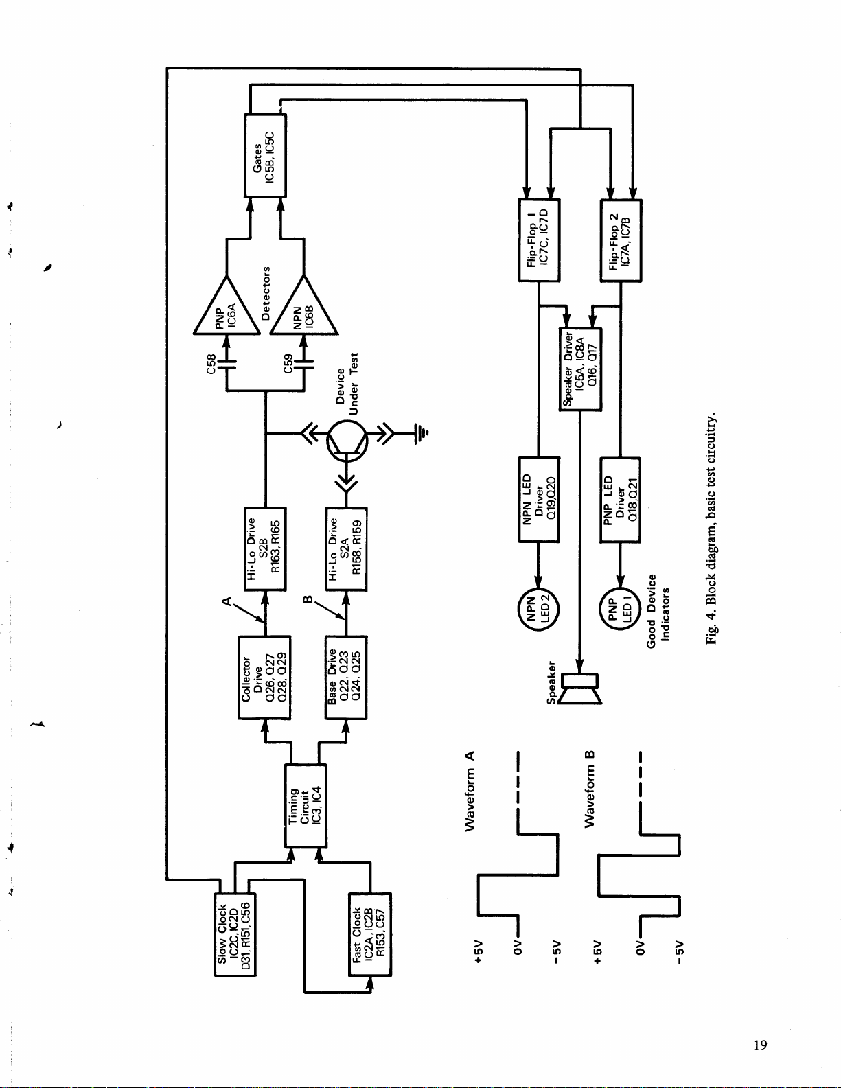
o
uo
=O
wo
('to
o
@
ol
c)
F+
3
g
o
o
o
o
o
o
0
('|d
O, ='
r@o
--N
uicno
HF
AT'
E\q
oo5I
.ts.H
oo
o
a=
)t
@
E
o
o
rH
EP
lo
a
ET
lDo
.$gF
1+
orcrb
NN'.
o09
.NN
oos
9-
g€-
o+
-iE
8-
g
EF=
o
F
o,
o
3FF
3ga
-R
g
@N
a€-
FT
N-
3F3
o:.
3=, F9
qe
;0
a9
*
g
C)
o
ut
(D
C)
v,
e)
;
!l
FJ
@
F'
A
7ro
C)o
o
E
:.
5
qe
31 =8'
lo
3
F=a
831
I
I
I
:ro
rid
aO
x{
)o
_a
j
r
I
!.u
,t)
(,lN
,o
oc
.o
E}
,,9
3[
,o
.
-tl
-
o
o
o
€
(,to(,r
t+
tj
ts
IP
t:
I
-1
I
);
(ro
I
6l
Page 20

period
time
be detected
can
only when a
detected.
the type
4.
The outputs
+5V
or
tested was a
P-channel. The output
a LED
drives
current
indicator,
P-channel
When either flip-flop
driver is activated
through the
Leakage/Breakdown
c.
1. The
2. Taking a
530 leakage/breakdown
externally
an
and. current
feedback, the
external load
A four-stage amplifier circuit
driver which in turn drives
meter
to 5 mA non-linear scale.
voltage
in which a
and similarly
PNP or
Only the flip-flop
of device being
of flip-flops
-
5V,
depending
good
DRIVER
to turn on
the
LED.
speaker,
closer
circuitry,
the
NPN/N-channel
I or 2 is latched,
and
indicating a
Circuitry
Test
controlled
sensors
voltage regulator that
(See
Fig. 5
look
refer to
NPN or N-channel device
flip-flop
P-channel device can
which corresponds
tested
can
I and2 of
on whether
MN/P-channel
from
the activated
which
corresponding
audible
voltage
power
DC
control
and schematic).
at the leakage/breakdown
Fig. 5
2 is enabled
latched.
be
Fig. 4 are either
the device
PIIP/
or
produces
good
automatically,
is used
the
and schematic.
flip-flop
enough
panel
front
or the
tone is heard
circuitry
supply.
PNP/
the speaker
device.
Voltage
feeds
to
drive
on a 0
meter,
be
to
uses
the
via
voltage-adjust
A
power
DC
panel
front
regulated circuit,
series
100V. The voltage
to
voltage and current
contrbl
external
The
3.
to the
switch
TEST
TO-TEST
When
panel
can
the
impedance drops,
fed
starts to
through
and constant
the
lOV. If
external
voltage
a
indicated current
will increase to
Further
complete
zeto-. The
can deliver
the
load.
external load
voltage
(NPN
SWITCH,
the LEAKAGE
is turned clockwise,
go
up to
load current
through
back
reduce
the load.
voltage across
the
voltage below
current-limiting
reduction
potentiometer is
supply.
switch is
short,
vbltage
This
LEAKAGE
regulator
sensors,
voltage
N-channel/PNP
current
load
only
and current
(device
regulator
is activated
and
pressed.
DC, but
100V
100
is
the
the voltage
the voltage
This
of
the external
impedance
on
5 milliamperes.
of the load
will
regulator
5 mA
potentiometer which
VOLTS
and
under
VOLTS control
the external
pA
voltage
output
100
about
circuit
the LEAKAGE/GAIN
reduce
to the
connected
control,
vary
it
can
is fed back
automatically
which
outputs
test)
is
through
P-channel),
this is
or
to maintain
pA
is reduced
is currentJimited
external load.
the
when
on
load
ture as
less. As
regulator
and current
voltage
will
continue
drops
load
the
to lower the
10
volts,
over and
takes
impedance,
load
to a
the
is
drives
zero
from
through
the
to
connected
polarity
the lever
PUSH-
the
front
the
voltage
long as
the load
which
sensors,
pA
100
reduction
until
to about
low
the
the
meter
up to
voltage
to
and
a
.ir
I
n
c
.l
is
a
Fig.
Voltage
Adjust
R72
5. Block
diagram,
Voltage
Regulator
o11,
o10,
o12
og,o12
R70,R77
Amp
Stage
tc10, D14
D15,
leakage/breakdown circuitry.
D16,
D17
External
Device
Under
Load
Test
q
20
Page 21

aq;
'v
aq1
tI
seq
puu
*
slql
l
eql
Eur
sr e^oq?
{1ecr1eu
ecnep
plnoqs
{po
{J?ru A0I
re^qep
dn
Iorluoc
sr
lBnlcs
eql o1
luorrno
sl
'srncco
prcads
Euraq ruo4
]uerrnc
aql
patfrsep
lsal
Jepun
eq
lorluoc SJ.IOA
pe]Frll
uoes
S
o1
pauJnl
luor;
00I
aEu11o,r
pue
u/r\op{?erq/e8urya1
o1
'paEeuup
er{t slorluoc
eqt
,(Q
aqt uo
laued
Vrt
ro
[BuJolur
luorrnc
a6e11ol
tcelord
aql
sm
rellod
eJBs eJnsue ol
lur{}
pazrsuqdue
lor]uoc
re^o
leura]xe
Iorluoc SITOA !ICVXVg'I
luou
'1euud
eql uaq/tyvru
aloq?
'asun4colc
aql ssorcs a3e11o,r
pBol
se
'Surxreu
'ssel
lrncJrc
zfu1rncr1c
echep
'Eurlsel
eqt
er{} uo releuorlualod
eql
'p?ol
}es
$
eql
eql
ilr/r\
Euol
sloJluoc
pore^{ap
[En]cB
1ICV)VST
esrr
Jo
scrlsrrelcsreqc
peqlrcsap
lsel
repun
,{1ddns ranod
-olnu
arn
o1
gCV)Vin
lauud
luo{
a8ellor
se 3uo1 sV
el{l /holeq
lrncrrc
u?J
SI-IOA
ngl
'4nur
-proccB
eql se
puol
u^\op)perq re^eueqtq
er{} eplJrelo
.S
eql
eq
eqJ
aql
r{c?g
IBuU
luo{
SI-IOA
laued
luor3
lenlcu
aql
'1aued
eq uuc
Fn}cB
lsel
rapun
aEu>1ue1
tuerrnc
aEuls-rnog
uaIEI^l
Jo
eql
IIBrus
}lnseJ
luerrnJ
laued
'raleu
uorlrod
e8ullol
Iorluoc
a8e11o^
ssel
,{lqeraprsuoc
lunlce
luerrnc
eq u?c
qSnorqt
'ragndue
ug^Iuc
r
Jo
eql
sl
u
'rol?crpul
les
aq z(utu
Jo
ueas
uuql
aEellol
B
uo ueas
oqt
SFII
qcrq
seEels rnoJ
00t
q8norql
eql
Jo
uorl?crpul
qll/t\ perns?eu
aqJ
'lorluoc
uo
eqt ,{q
ssorc?
oJr^ep
urnl uI
eql
do1 relaru
,(leluauEes
'7\00I
Vrr
l?urolxe
pel?crpur
eql
acuepadurl-q8fq
ar{t
p?ol
al?cs do1
repun
ragndtue
os
'e1ucs
qll^\
lurnurxur.u
puol
er{} uo
Iuurelxa
ro
Jo
eW
lsel
so^rrp
rrp
eqt sa^Fp
leql
SC\;XVE-I
eql
1nq
.{eu
luor;
psol
'releullo^
echep
0€S
e
eqt se
'raleu
? sa^up raglduru
eql
aEuur-aprlr rueu{
SiIION
+
t
17,
Page 22
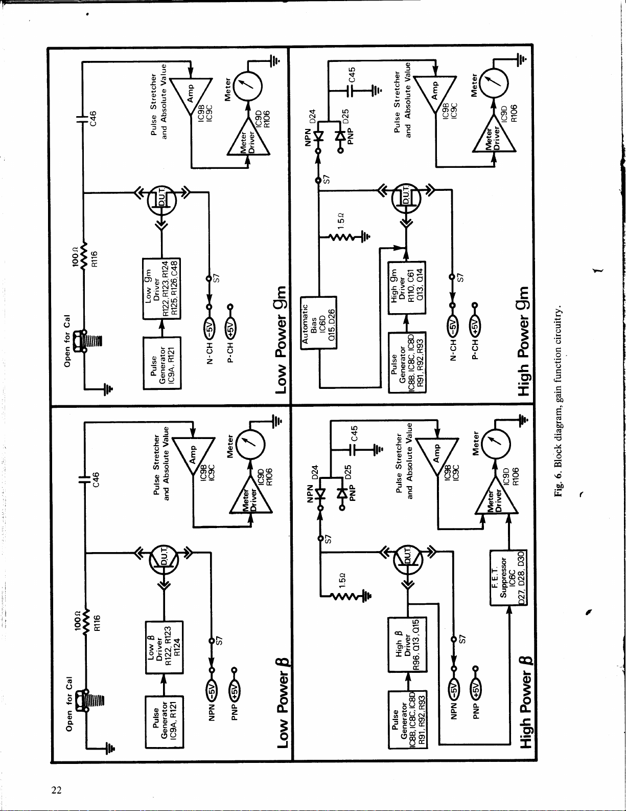
a
q)
h6
i>
9o
e7
o6
3<
E:
bEE
E
o)
E
C)
o
tr
q)
o
o
OO
Zo-
L
o
3
I
3
o
J
2oc'i
6Ea
E
O)
L
o
3
I
?
-
.9
T
()
(J
o
bo
o)
OG
c)
9o
g5
oa
ar!
g<
f-
0-E
c)
Es
9E
6E
!€
o-E
ro
bo
€
)l
o
E
\o
bt)
tr(
q
cf)
q
G
o
o
g
o
ct
o
9:
6g
E8
o-B
o
J
22
Page 23
lse1,
uluC
'(I
0€9
eql
Jo
sJolcuJ
d
apnlcul
B JoC
9
t'
'C
t
oql
pus
'I
urnl
qclql\
eql
prr?
'Vr,gS
a8e11o,r
enp^
aql
sr
pear
eql
aqnd
peqrrcs
A\OT
eql
eql
les
oql
eql
tu8
eql
U00I
3ur
eqt
[r1rncr13
lsel
utu8
eql
puu ranod'no1
lool
rasolc
rello;-,no1
gf
qcFl,t\ ro}
rolerauaE
las
oJe
'lBnlrBru
pelceuuoc
sI
rolcolloo
'tolstsat
sasodtut
seluraua8
Jo
,{lqtqedec
paldnoc
ulllgw
NIVc/gcv
cnueu,{p
,(llcerlp
ra,no4-rtro'I
ur
pud
*E
IEC
ropun
IEC
sl
e
qSnorql
'[Bnu?t'u
palcouuoc
sr
ururp
'rolsrser
lgg
a8ellon-o1eg
UgAruC
ul?rp
'ro]slser
aql uo
sr a8ellol
anp^ elnlosqu
UEIIIru
,<ncrtc
Japun sesl^ep
(..elag,,)
roJ
pleu roJ (..ecue1cnpuo3
}B
aql
'crl?ueqcs
5|
re,rod-lrol aqJ
1e
sunr
essq eql se^lrp
repun rolslsuerl eql
e
q8norql ,{rltncrtc
aql o}
-
uorlecgudr.ue
repun rolslsu?r] eql
qclq^\ re^o
lvrr le^el
aq}
eql ol
'ragqdure
ulIAIuo
IUE
ramod-rnol
urE
roluraueE
1
uEAIuo
1sa1
Jo
seues
ol Surproccu
eql ot
-
uorlecgqdu? puu
^\o[ repun
uI?r(I
luaJJnc
ureE
peldnoc
lceJJe
rairrod-q8ru
ureE
e sasn
eq} se^lrp
Jo
lsal
sI
seues
ol Surproccu
Jellltue aqJ
AS
ol
pelrouuoc
paldnoc-3v puB
rtrlrncrrc
'
d
^\ol
eql
g1 8ur1es1nd e
'Vr/
ssorcu a8ullozr
'.,trel
'rolslsuurl
eql
qcH \
Bleq-t\ol
er{l uo
roJ
pesn
'(aroqe
qcF{r!\
eag)
ol
pelcouuoc
luou
aW
Jo
ecrnos eql
AS
ol
pelceuuoc
paldnoc-3v pu?
'frlrncrrc
tu8
]uoIrnJ
eleE oql se^up
aEe11o,r sul
,{11pqudec
UIIAIUC
NIVc/gcvxv[IT
aql
sernseeru
aseql
'lsol
lsel
Jo
Jo
,tlddns
aql
pue
'stolstsuutl
'socr^ep
,(laluurxordde
pelcouuoc
luor;
eq]
Jesn
NdN
uu
ng+)
punor8
,nol eq] o1
lse]
B suq
u00I
er{I
reqclerls aslnd
puu
pagqdue
uB
lsrolstsuerl
ggg
UE1IUC d mOf
ol
leuud
rog
d
uo Eurpuadap
rolcalloJ
saslnd
ulnl uI
llnJulf,'co-Ino
'Iele(u
Jo
ralourered
u1
gf
passorduroc
eql sosn
aql
sgql
eql
laued
rrB
',t1ddns
eql ol
lsot
sl
selureueE
te^el
Jo
eslnd eql ol
or{J'regqduu
qcF{,l\
rolereue8
eqt
pr.ru g'Elg
}sel
tu8
suollcnrlstn Jesn
leuuBqc-N
AS+)
roJ
/l\ol
tuE
roJ
pes?Iq
pu?
'(SSO1)
qlrm
ern
'IgC
pagqdu?
rInJuIS-do-Ino
uorlucgrlduu
sluauoJns?au
-iuer1,,)
qloq roJ
ol
regar'r{rlrncJlc
'EIC
aslnd elulr\-eJunbs
rolcalloJ eql
eql se^lrp
ranod-nol
-eraua8
sF{I
'zH
ur r{Jrq^\
ropun JolsrsrrBJl eql
'lsel
d
lsal
aql
'saqcluns
suorlcrulsur
ur
sr
JolsrsrrBJl
ar{I
'(dNd
U00I
q8nonll
uorlsalep
Jo
s?Iq
poxlJ
UEAIUC d mO-1
-radns
luerrnc
sql
'rolslsor
ar{l
ure8
sr a8ullol
etnlosqu erlt
eq]
paeJ
-)vET
rolsrsuurl aql
'elBJS
elen-arenbs otuus
d
-ep)
oqt se^lrp
;o
elu8 eql se^lrp urnt ut
'(c4euaqcs
,{rlrncrrc
eJ? r{cTrl/rl'seqcluns
s1ql
uI
JEC
$
'(lauueqc-d
?J00I
q8norql punor8
uorlJolep
orez sll
A\O-I
eqt
Euqeqnd u
'7y7'
oqt ssorcu a8ellol
-puadop'fier[I/y\
ar{I
ul?rp
oqt
puu raqclarts
soEnd
peeJ
eql se^lrp urnl ut
'Ieletu
-n
eq;
Ig;H;
q3rg
'€
eqJ
qcFl/r\
u Suuruq
008
JiISrt
ur
Jo
eql
rr?
Jo
ar?
ur
Jo
oI
t
o1
eqf
eI{I
les
er{I
oql
osp
eql
oql
oI
aag)
AS+)
lq8laq
aqt
erll
B re^e
'CCA
lncrrc
'(aloqu
repun
aslnd
'e1cr(c
lsn[,
rapun
'ng1+
9
'Erg
pelceuuoc
luor;
NdN
roJ
ru^\
II1JUIJ
elqesrp
uorlcunf
rolsrsrrurl
oq}
e^rlcoJep E
lualerd
la,no;-q8g
roJ pasn
UEAruC
IgC
e
q8norql
'pnu?tu
esrnos
AS-
polcouuoc
IEd
Eurleqnd
aq;
US'I
r{6norql
..uo
'1sa1
uo
A\ol
cruuu,{p
rl
5|
ra,rol
ranod-q3q
g
}B
suru
%I
'\np
eslnd
UOIVUEN:IC
0r{1 so^rrp urn}
eqt
puu
d
oq} o}
laued
suorlcnJlsur Jesn
sr rolsrsuerl
aql
'(arua
e
qSnorql punor8
',{rel
'rolsrsrruJl
o1
pegqduru
IAC
sr
u
aW
sHI
q
o}
qEnorql
luerueJuuque
peoJ
se^rrp urnl
aqr
eql'ratetu
sr rolsrsuurl
sr
uossauddns
aql
'a8u11ol
9'
:f,CA
:rolsrsu?rl
eqt sesserddns
Joletu
tuE
ronod-qEq
tuE
qElq
qclq/y\
9
aeg)'lsel
'Etg
Jo
seuas
01 Sutprocce
Jo
u?
',!ddns
raqJlerls
pu?
rapun
66p
ulurp
lrolsrser
uo Sutpuedap ,{rul
SVIS JIIVru
lmcrlJ
'4cuqpaeg
'uorlrpuoc
srql
do1
z(1lcar1p puar
sesn
B
,{laleuxorddu
'a1c,tc
0t
,{raaa
aql sa^trp
Jo
esBq
aql
lso}
soqclrl\s
sF{l
w
?JS'1
oql
aql
snoeuorJe fue
pelse}
lrncrrc
lecrdrtt
JI
sql
lsol
repun ecr^op
eql
puB
U1IIEI4I
'uorl?trpur
al{l sosn
d
renod
rolereue8
urnt ur
oql
pue
ol
palceuuoc
}uor;
eW
resn
leuu?rlJ-N
AS+)
IoJ
urnruuure8 u
qSfq
LUE
ecrnos-o]-ele?
lueJrnc
3u4sa1 redord arnsw
rarrrod epou
sosuas
gsnfpu
a8e11o,r serq
aql
qc1l/r\ go
acuelsnpuocsu?Jl
eql uo
iISTnd
gg
'zH
qcFl,r\
d ttgUf
'('crluueqcs
,{r11ncr1c
eJ? qJrq^\
pelJeuuoJ
rolce[oc
pelur8alur
uiIIEI^l
,,t11car1p p?or
relotu
sF{} w
asuq
sr
oql so^lrp
oq]
laued
lgc
qEnorr{l punorE
epop
anp^ olnlosq?
lsel
eql
'JESur
eql
los
aql'Fnwru
eql ol
-
sr
aq} uo Eurpuedep
NIVC/ACV)VAI
Bleq-q8g{ crureu,,{p
aql uo
'uorlsod
eql sesues
osBq
rellnuo
s e3u11ol
,{lqugord
IEc
UE1IUC
aspd elues
poqlrcsep)
orlt sa^Irp
alu8
go
lsal
tuE
sor{J}IA\s
suollcnrlsul
sr
'(leuueqc-d
uS'I
eql
ol
1u
'atu11ol
aslnd aEellor srql
,,t1ryqeduc u.reE oql
qloq go
uB
's.IgC
ur?rp eql
alu8 eql
uroJJ ,{re,r uec
HCIH
uE
qllr
UEAIUC
AS
H
suorlucrpur
u
ur
'('crluuoqcs
'ragqdure
uo^rrp sl
aql uo Eurpuedaq
-
JO
Ibler.usred
o-I
pessarduror
tu8
UOIVUAN1IC
saslnd
ol spuodsarroc
B
ESTnd
rlrlrl,r\
Jepun rolsrsusrl
'lsel
sr
rolsrsu?r1
seuas
e qSnorql
o1 EuryrocJe
Jo
rellrue
,,(1ddns
o1
potceuuor
aEulloa srql'rolslser
aslnd
.{1ryqeduc um8
saslnd Jolcailoc
qcFl,r\'ugnluc
-gO-JnO
ralaurered
d
'eluos
-uerlt\
IEC
e
r0l1rl.u0
ugo dorp
uuql raq8gq
IgC
ro
uossguddns
ragndue
rolurauaE
E
pud
HCIH
I'uE
Igd
eqt
.(rlrncrrc
er?
qcnl^\
sFIl
q
o1
polJeuuos
sl
u1plp aql
puu
'rolsrsor
q81q
uB
?
,,(q
%I
finp
ssorJ? a8ullol salereueE
mlrr
lqEleq
al{lJo
'IAC
uorleldep
pu?
-OIgV
luerrnc
'puu
aEellorr
B roJ
eJr^ap
AI
I
01
UAAIUq1
EZ
Page 24
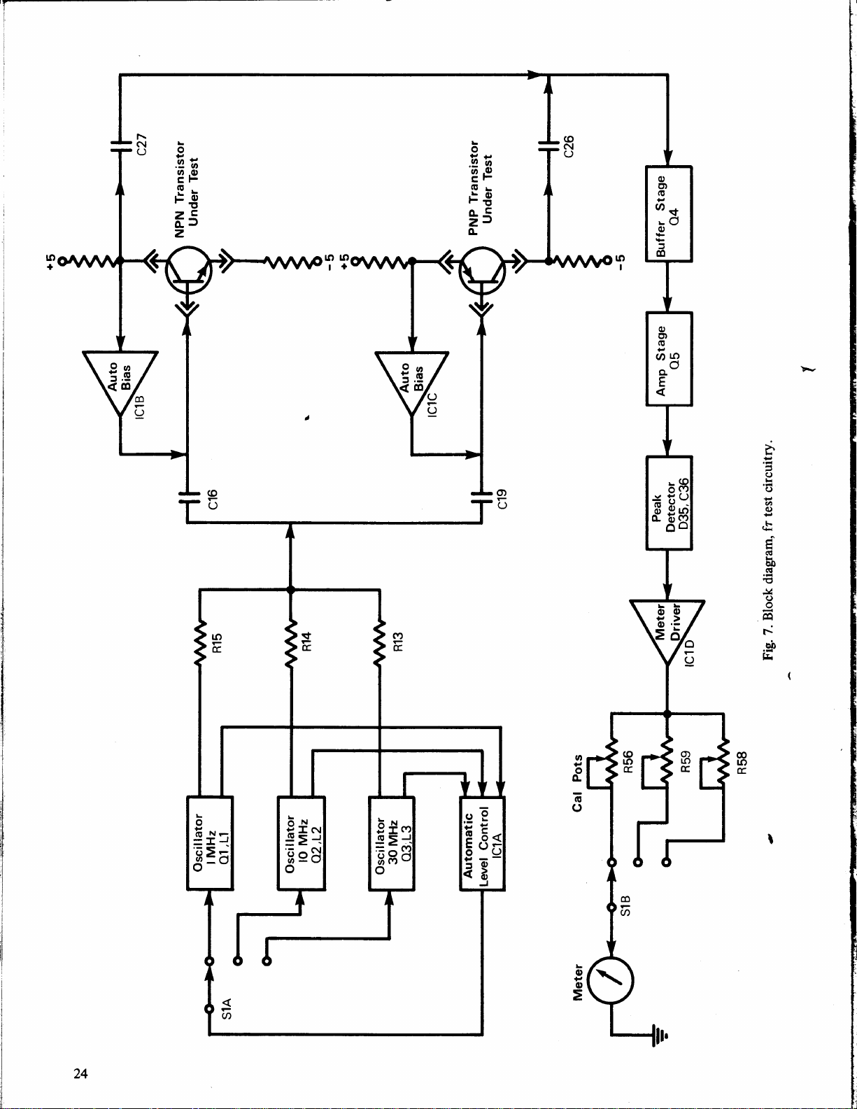
8E
-o
.2
o.o
CF
€
EO
'!t
ZE
cJ
z
b
EA
trF
Gs
F€
aS
zJ
o.
=
(J
O
a
o)
,t-
tr
c\t
oo
ctt
E
J1
O
o
o
r-
ob
tr
24
b
E+=
E=u'
t=r
HeB
o
@
ro
E.
E
c
o
O
o
B
Page 25
sasodurradns
'aEe11ol
aq;
eqt
IAd
sl
6tS
lcnpord
eeq}
resolc
fr1Jnc43.4
go
{ool
'crlBtuaqcs
'!l
aql
polurSalur
q8rq cruruufp
uo
puer
4
relodrq
Jo
cr}suelcBJ?I{c
fcuanber; aleredes
qJll,{s
lB
eln
4
LL'V'aLU
ulerp
u!IAIU( uglgw
IH
eqt
tu8
frltncrtc
1s1ale1
pu?
oql
suotltsod
are saqnd
uI
qcF{^r
'apcs
'srols$tr?r1
$ sJolsISuBJl
'{rlrncrrc
urnl
IINJUIJ.dO.INO NIVC/gCVXVAT
ecuBlcnpuocsrr?rl
e{t sorn$otu
sqt
q8q
roletu aanll
ol
reJer
01
pagqdtuu
Jo
raleruered
perns?eu
of
puodsarroc qcu/h
t
pu?
'ttt
acrnos-ol-a1eE Eurluqnd
peal
eql se^llp
EqI'IA}Etu
aW
qlprmpuuq-ureE
fcuenberg
een{l uo
eql
B
rog'selecs
eql
Jo
'lsel
uv
er{}
eql
eql
roJ
eeql
:sarcuanb
eql
Eurldnoc
e^rrp eseq
'ECVJS
uglc
4
aql
poun}
0I
'I
louINoJ
eqt alulnEer
svlg olnv
0I
roJ
pegnduru
o1 rolrceduc
eql
'gCVIs
UgIgW
0€
prrs
u ol slndtno
sl osn
ur rol?iltcso
eql
o1
rolrcuduc
lrncrrc
}sol
Jopun Jolsrsu?r}
vur
Fr.6ls
reJJnq
orIJ
UOIJ1IIEC )Vgd
puB
'Ugnru(J
uV'zHW
pexg
peJ
aseq
puu
rolceiloc
sl
prfrs rolce[oc
Fp
CC
aqt
w
qcFl,t\
aEuer eql uo anp^
Jo
aEu11olo1-luarrnc u
eqt so
pu8rs pagqduru
'pesn
aarql elureuaE sro}?ilrcso
eql'le^al
q8norql
aql
'luerrnc
sr
a8ullor
urnl
4
es?q
JIIVWOI1V
rolcelloc eql sesues
,{lecrleuoln?
qEnorql peJ
reuo^uoc
rolsrslr?rt
le^el
-er;
'Igngl
ol srol?flrcso eql ol >lc?qpeeJ saprrrord
1nd1no
pt6ls
B
Jolsrser u
puu
repun
rolsrsrr?rl
Jo
luerrnc
eql selJs^
Eurldnoc e
UgCCng
-I'IdWV
erll
ul
peurlcer
o1
sr
peJ
eql se^lrp
relatu
SiIION
s(,
Page 26

MAINTENANCE
AND
CALIBRATION
A.
I*akage/Gain
1.
2.
J.
4.
TEST
SWITCH
"Zero"
Meter
Turn the
GAIN
suitable
meter
Turn the
GAIN
proceed
(19) does not
<iff,
panel
bottom
Plug
zero
driver
trimpot
With power
(10)
BETA/FET
BETA"
should read zero
bottom
Model
(19)
meter
Screwdriver
and adjust it to
Model
530
(19)
meter
to step
unplug the
by
panel
in the unit
control trimpot R-87
so that
location.
"LO
to
(4)
H.lf
indicate
unit
removing
and
meter is at zero.
on, set the HI PWR/LO
PWR" position.
Bm
position.
panel
of
TERMINAL
Calibration
power
530
does not
in the hole
power
indicates zero
the LEAKAGE/GAIN
and remove
the
two on
and turn
switch
LEAKAGE/GAIN
on top scale;
the 530
off.
indicate zero,
indicate zrjro
on, if
zero,
turn the 530 power
the 530
five screws
panel).
back
power
with
Refer to Fig. 8
Turn
(9)
to
and adjust zero
STRIP TRANSFORMER
If
LEAKAGE/
just
the LEAKAGE/
on.
suitable screw-
"TRANSISTOR
if not, remove
insert a
below the
on top
on top
TRANSISTOR
scale.
scale,
meter
bbttom
(three
Adjust the
PWR
switch
meter
p
on
for
(19)
CAL
trimpot R-106
holding
(9)
in
the LEAKAGE/GAIN
top
scale. Refer
B.
Leakage
l. LEAKAGE/GAN
2. Plug
3.
4.
5.
Circuitry
calibrated
the Model
power
on.
Set
Test switch
NPN/PNP
Connect a 5.1
milliamp
sockets
connected
meter).
Press
Model
adjust front panel
so that
with
the
TRANSISTOR
"TRANSISTOR
Calibration
per
as
switch
meter, to the
(6)
of the 530.
to
the
530 PUSH-TO-TEST
the
external
suitable screwdriver
to Fig. 8
KO resistor
meter
meter
section
530
into
(a)
to the
(12)
to
positive
LEAKAGE
meter reads
SPEAKER
(while
BETA/FET gm
BETA" position)
(19)
for trimpot
(19)
"A"
power
top-most
"NPN/P-CH"position.
blue
(Blue
lead
reads
should
above.
source
in series
yellow
an
socket
of the
switch
VOLTS
0.9
milliamp
switch
so that
zero
location.
be zero
and turn
position.
with a DC
test
should
external
(13)
control
Set
lead
and
(14)
DC.
on
I
be
MAIN P. C.
26
BOARD
FRONT PANEL
Fig.
8.
Bottom
view
of Model
TEST
SCREW
530, with
bottom
#1
panel
removed.
F7 P,
C. BOARD
Page 27

.J
'9
'L
'I
'Z
't
'n
's
'9
.L
S#
ul
eql
puar
En6
006
..C,,
les
'0€S
1se;
unt
ulBtu
Of
d
€0I-U
lauud
plln8
'ElC
retuoc
'g '3lg
tulod
'(g-af)
IH
gctptts
Jo .,J,,
plnoqs
lepo4
gtg
006
puer plnoqs
006
'Vrt
tuopoq
'1aued
6Eg
aq1
os
Vrt
'uorl?col
tuE/u1ag,no'1
Enldun
Luolloq
6
e^Ilslser
Z
ol
lcetruoJ
paE8nld
oqt Sntd
..VIgg
..VIAB
lceuuoJ
e^I]sISeI
,.VIgg
olq
qllA1.
l?ql
dol uo
uolloes rad
'66V,,
eql
,iq)
Iauyd
pu?
;lasrnof
u
'(s1oduF1
UOot
oql e^oueg
tuorg rer{s?/h
lxeu
ol
l3ouuoJ
4romlau
:(3-41)
(6
'EI.{)
ol
reJa1
eql
ot (Zt)
(7)
qcll'ts
olur
e
I}sISar
ro,uod
IgC/VIgg
I'uB
p?er
'J'd
re^up^\elcs
IiId/VIgg
urE
'epcs
>[ro^\]eu
IAC/VISS
tu8
Vrr
do1 uo
eql
Enldun
ramod aql
alqelrns
'epcs
uop?rqllB3
releu ureE/eEu4er1
lapoq
'0€S
Eunourar
uo o^u
elduts
paxu fq reqlte)
u099
e4lslsau'o'49
l1etus
Jo
1mq
egl
p?ol u
(6
'Etg)
osp
ulutu
pu?
'g'Elg
U/t\d O-I/UA\d
OT,,
'uo_Jqpod
'(uotltsod
..964
0I0
eq
plnoqs
lsel
onlq eqt
lset
enlq aqt
{rolueu
0€S lapo1,t1
olq
t)
(t
qctp*s
qclpr\s
os
01 roJag
uo
qcll^\s
'Etg
tsel
qclms
oql
Of
lBrll
'S
.,0S,,
prsoq
opq/rt)
anlq eql
'ugg1lsod
loduul
NIVC/ECV)VA'I
JI
'elucs
0€S
pue
acrnos
pue
'rallrp,rarcs
NIVC/ECVXVE-I
ralau
8
ot reJeg
'3lC
puu
e^U egl
lced
e^Ilslser
srolslser
onz aq
'(1aued
ro
1ro9
plnoqs
'{ro/rueu
ISgI
SurpunorE
uTetu
'C'd
uollngqsnd tqt
}ulod
uoel\leq
pu?
lceuuoc
B
peel
pr?oq
'J'd
qctpt\s
eln
q
'pBe[
peel
eql
'uo
d
Sqptoq
(O)
ol
p?e[
urnJ,'(O'Etg)
Jo
'(Ot)
tos
'uolltsod
..HJ-N/NdN,,
qcFI^\
la{cos
'(O '8lg)
renod
urnl
ot (O)
NIVC/gCVXV1IT
JI
'el?JS
IzI'u
oqt
ut
Jelou eql
lulod
eql
ot (e)
(0t)
releu
lou
saop
reletu
roJ
's,r.erJs
{ro^\}eu
^\arcs
'(qclvrrs
lsal
lsotu-dol
qlp\
etlt alotuer
luadar
dals
lodruul lsnfpu
sp?ar (61)
lodurrl
s?
pelurqllec
uotloq eql a^ouer
uo eaql
u/r\or{s s3
Eu4sn[pu,(q
I#
pue
le)
aqr
pr?oq
ol
reJeg
Jo ..V,,
ar{l
lsel
preoq'C'd u.Iptu
lurod
uee^Ueq
E
lutod
Iapory
eIIl
dNd/NdN
re^{I
'uor}tsod
'uor11sod
eq
ptnoqs
lurod
ot'(9)
ocrnos
prr?
UOISISNVUI
UOISISNVUL,
(Ot)
Ioletu
1snlpe
'lou
olqBllns
UOISISNVUI
UOISISNVUL,
uo..0S,, spuoJ
Jo ..8,,
oql
UOISISNVUI
UOISISNVUL,
NIVC/ACVXV15
Ieloru
'o
'I
'Z
'€
'v
's
'9
,L
{ilH
teql
pu?
pn
les
ro
(61)
pr8oq
raJeg
roqs?^\
01 (0I)
S-OI
qSnoq]
qrll,t\s
repun
'1awd
uruS
uInI
eqt ol
'(ot
tqsn
pue}xg
IH,,
d
'e1ecs
oq)
suo[]
En14
plnoqs
lodurrrl
ot
'g '3lg
lceuuocsD
sll ol
utETeeU
su uoll?Jglluc
..O-L,
ol spsel
eEelcud
..qgOC,,
pue
'(lq8q
'uorltsod
dNd/NdN
..(IOOC,,
,!puap1
'lsel
p?o[ rolcefioc
}ceuuo3
l?]uozlroq
13o
'adocsogtcso
'qC
'0I
qderE
peprocar)
q
uolloesre]ul
9,,
pertnber
..'TVJ
Enldun
laued
uronoq
1ou
pu?
aq1
IInJ
p?er
IIB
NIVC/gCVXVET
red
t{cly'ts re,|od urnl
rerrrod 3
acuop
..HJ'd/dNd,,
qg1
sll ot (0I)
Jo
doairrs
eslnd
ur
Jo
palcalord ueqrrr
..0|
JI
o1
lepory
lopory
uorslsNvur
'elecs
I0I-u
qtl^\
NIVC/ACVXV15
oqt
Enldun
'spBel
FUFFo
uollurqlp3
Ietetu
uollcas
I)
uo (I
'uorlrsod
illt\
'(op
suolltsod sll
re^el e^?el
(ZI)
qctpt\s
'uotlsod
.,(1uu1od
..dAld
IH,,
rolcelloJ aql
lcouuoJ
ue
adocsolpcso
adocsolllrso)
'('aP/t1o,t
UOISISNVUI
proceu
'EIc
dels
pclue E
leq]
uo
oql
Jo eAotuer
gES
0€S
pFoqs
0I Jo
UOISISNVUL,
aslnd
a8ulloir
I
'I
uo
'(S
eu[
oq}
opcs
Jerfiorr?
lopory
lasdn
lorluoc
otuJ
rgc/vrag
speer
Ielotu
0€S
lepo4
1se1
aceldag
'uorlrsod
(Ot)
'..V,,
oql
pu?
lcouuo3
,(ue) ro1s1su?Jl
}sol
e^ow
[]un
eqt
HJ-N/Nd$
ro
lsol
reelle
ol
s?
IH
les
'uotltsod
Jo l?unurel
adocsogtcso
ranod eql
peel punorE
tes
eq
'AIC/CgStu
tgg/Vlgg
uE
..VIgg
a8ullor'
putJ
eql
}BtIl
tuor; eql
eql
qlr/$
srx?
pcIlJeA
'Sutpear
sr
enpl
pu?
gtg
palurrd eql esodxe
lsel
'sEqttes
ramod eql
uF
lsnfpe'touJI
ro^rrp^\ercs elqBllns
IInJ
tuog
I#
/r\erJs
ot raJog
'g 'Elg
eq
plnoqs
aorql aql
rerrrod
t{cil/t\s
l1un
HC-d/dNd
(t)
qctprs
q
fq
pal?cryu
oql
rapun ecl^ep
eq}
ol
JC
o1
pu?
qcll^\s
'uotltsod
tqEleq
(n)
'sruroJe^?n
rqSlaq
eslnd al{l
lBluoztrol{
'1utod
puoE?p
ppol{s
procau
uo
qcrl,t\s
fH,,
or{}
e^oruer
lmcrlc
rolstsuuri
'eornos
0l (o)
'J'duI-BuI
os
'el?cs
ranod
prrB
otez
qctr^\s gnruC
lsol
rolsrsrrsJl
(t)
sel?crpu
durel
t?qt
,.HJ-N/Nd1q,,
eql
U/t\d O-I/UA\d
rolsrsrrBrl
eql 01 aqord
'lsel
{c?q
qll/r\
Iecrlre^
(0)
o^resqo
'8tg)
(u0
'sIXp
eI{I
auq
oql oq
enp,r sFIl
..d
aW
'pr?oq
-ceuuoc
urnl
eql
17,
Page 28

Hi I Meter
Scale
Fig.
"TRANSISTOR
pot
R-92 with
AGE/GAIN
value
CAL"
of the LEAKAGE/GAIN
p
11.
Hi
calibration
BETA"
position,
suitable screwdriver
(19)
meter
(found
reads
step 6) on
in
meter
chart.
and adjust trim-
so that LEAK-
the recorded
the
"HI
p"
(19).
Pulse
Height
in
Volts
"HI
scale
p
{V}
Fig.
(d)
Adjust R-22
milliamperes
(e)
Remove
sistor
with
lead
be
between 9
operation.
NPN
12.
Field
NPN
into front
current
(See
Fig.
PNP
Socket
B
calibration,
for
a
(See
Fig.
Transistor
panel
meter in
l3).
Current
1l
and
Socket
fr
circuit.
collector
8
current of l0
for
location of R-22).
and insert PNP
socket
labeled PNP
series with
measured
milliamperes
the
for
Tran-
(15)
collector
should
proper
E.
fr
Circuit Calibration
1.
Tum Model
meter
screwdriver
adjust
2. Remove
the
two on
3.
Turn Model
plugged
meter
on the RANGE,
(18)
zero
4.
Calibration
Equipment
(a)
(b)
(c)
(18)
does
in
530
it to
indicate zero
the Model
five
screws
the
back
530 power
into fr
(18)
reading
does
not read
reading
(Fig.
of
Automatic
Required:
.
o
good
4ny
hecision
Any known
sistors.
Tum Model
Insert NPN
sistor
socket
Place
current
(See
lead.
Fig.
off.
If fr
not indicate zero,
530
just
below
on
the
bottom
on the
the hole
(three
panel).
on. Without
sockets
MHz
(15)
of zero
Switch
zero,
or
for
(17).
adjust
8).
Bias
Circuit.
quality
Model
530
Transistor
labeled
meter in
digital Voltmeter (B
2S0).
good
NPN
power
on.
into front panel
(16).
NPN
series with
12.)
OUT-OF-CIRCUIT
insert
a suitable
the
meter
top
scale.
panel
bottom
any
(16),
each
range
If
R-55
by
check
the fr
to obtain
and
removing
panel
and
transistors
for
fr
selected
meter
& K-
and PNP
Tran-
tran-
the
collector
Fig.
13.
Field
calibration,
5.
Calibration
a
oscillators.
Equipment
.
of I MHz, l0
Required:
Frequency
Counter
at frequency up
Precision
.
Any
Model 1801).
NPN
transistor with an fr
fr
circuit.
MHz,
and 30 MHz
-
100
mV sensitivity
to 30 MHz
(B
of
K-
&
greater
than 500 MHz.
.
Non-metalliccoil-adjustingtool.
(a)
Tum
Model
(b)
Insert
NPJrl
labeled
ments
location
NPN
are
of
TP-4
530 power
transistor
(16).
taken
at
and
on.
into
front panel
All
frequency
TP-4.
oscillator
measure-
See Fig.
coils.
socket
8
for
28
Page 29

adocsoglpsg
'Etg
1og
les
r
i$
.zHI
oEueX
a8usg
6r4pter
(c)
(p)
ro;
t"r
l
'9
ruaurdlnbg
'
j:
roleg.nsg
e^B^r eqs
9TfS3;
?J)I
trc
%S+
7J029
IteuuoC
o^$
u! u'roqs
Jo
uoF?3ol
e6urg
(8)
1ql
'
'
roJ
1oS
t"l
9s'u
(p)
- .
(a)
G)
Cl
(q)
lsnlw
1€S
1ag
eqlJo olo's
oEurg
lndrno los
lndlno
e8urg
4
Jo
A9.Jo
(ft)
qclu.S
qcrytS
\laq
JEaIll4Jo uoIrBlqIPJ
or
or (lt)
8'6
uaa
ifri"i$*H*'",i"i
sel"cs
'00I-0
zHtrl g6' uea,nloq Er4pear e ro;
pue
'005-0
zHIr{
ptrB
TJ[,i'&
:parmbeg
q{'r{ edocsolJ.Itso
, $|"{f1lil?
elqeduc
w
ql! \
'bs+
NaIN 0€9 IspoItI
'tI 'EJd
'9S-U
qcrlts
o
3o
ll?'{t/I
6S-d
or (lt)
[rmlxruIru
uo!s!rard_)
1nd1no
Iopow
,."r*rr-"
na^-tll
rolslsor
salres u! srolslsel
pltB
rorsFrrgrl
ra'nod ulnJ,
'so
pue
'ml'o
*^T$*:#""1*li.",lltll3
99 3o
3 roJ
qql'tls
qcry*'5
Eulpter
rel3tu
'(8I)
ol (rI)
'005-0
I l?uJalxa
zHI4l
pso
.{?od-ol-)pod
o, *
,r$l}jtJtHr'li$rr"ri6$
or0t)
'00st-o
p1a1g
'71
rsnhv
'4lt\l?O'l
1snfpy
'zHVl,Z'Ol
;Ti,fffi
PuBq
qlPL{
z4rr rapow
e Eulcnpord
AI ;o
rolslsar
rqtos
'(8S-d
uo
4;'1 1
-or-ped
,o
gol€g
euo
pu?
^,,^ -,
lJeuuos
ol
-(9-I)
s3
L'Eg:"sl
,or
rorerrrcso
dol 3q1 uo
JoJ Jol?
.qr
dol
,J
'uoltsrqllec
'I
'tmrrlr
(1) I'I
(D Z1
pJEog
'J'd 'd
6
("1
.
.
.
(q)
f"l
(p)
t"l
G)
.
.
.
1nd1no
lsnfpV
aleJs
Jo I?^oura1
iql
u[)
ruo.r;
tt'i[
Eq
urE
urnl
eql
earql
'rarl?d
ulstu
rndrno lag
go
;o
n9'
8S-U
Jo
aJwas
rrr?{u
s ruc
tffi
./ar\
dNldr/Ndn
.no*., 6l
lorluoc 91194
rnu
lsal
"oo-.-, iiff"i
uror;
oql
'dnpwd
.qr-"^o."li
\3JJs
o^otxou
xrs oqt
W1,rr
pegpuepl)
E roJ
relaur .4 orn
'(91)
seJnparord
PIEoq'C'd
6u1,nogog aq1
qcry,rs
.(s)
uA\d Ilr/u,na
rser
qorq
'(91)
aq1
qclr,ns rolcalas
0€S lapot{
loued lolluoc
,1"rq .q1 u1 JiJ.ti
'J'd
pa]Bcol prvoq'J'd
rzou srnarcs o,n;
s,na.s aarr{J
ruau
reou ^\errs eu6
I Furolx.
zHI^t
'4ead-o1-4eed
Eulpuer
gg;o
roJ
rolcaros
pu? qoorl
'(6)
Je^o
1e'ud
lceq
'a?rals6
aqr
ruorg nlnclpuodred sduc orlt
:ssqclpns
rsal
ruoU
os
u$op ece;
lsuud*6iroir
uolloq aql uI s
pr€oq
1uor3
prlrrral
qrl!^rs
eqr
aql a^ouar
ll t?q]
pw
xq
1sa-reau
(8 Eyg u11s1ra1sz ue
:sao[[oJ sE
'1euzd
.laued
'dgts
rolral.s
'(zI)
sall
4orirar
Prrs lewo
Sullunou
roJ rot?Ilrso
dol oql uo
:h;;;";F;ih;';;ii;;tp;1"""
(Taued
qcrgs
aCvxvil'I
-tunour
IflC/VISS UOfSId(Vifi
qlla
rrlolloq eqt
oqra
o^rl
uoroq eql
s,{errs
eqlruo{
6Z
Page 30

(h)
2.
(g)
Being
careful not to
front
edge
toward
the transformer.
board with
in the vertical position
components.
To replace
previous
Removal
(u)
On the
and
RANGE
(b)
Turn
the
panel
of the
the
front
the front
the
steps for removal.
of fr P.C.
control panel,
remove
the Model
control
up,
MHz
panel
the
switch
main
so that
Next,
main
board
mounting
530 over
face
break
any wires,
P.C.
board
the
rotate
edge
up with
for
full
P.C.
board, reverse
for
service.
pull
to remove
(17).
so that
down
and
back
edge
the
main P.C.
the
access to
nut from
it lies with
and the
raise
the
slide it
clears
board
all
the
the knob
the
bottom
NOTES
(.)
Remove
three
screws
screws
panel.
(d)
Remove
(identified
fr P.C.
board
o
Two
o
Two
(e)
Lift the
suitable position
ponents.
(f)
To
replace
previous
the
bottom panel
in
the
in
the
back
the four P.C.
with
located
screws
screws
fr
board out
the fr P.C.
steps for removal.
bottom panel
panel
board
an asterick
as follows:
near
back
near front
for
access
by removing
nearest
panel.
panel.
and
board,
mounting
in Fig.
rotate
to
service
reverse
the
8)
and-
bottom
screws
fiom
it to
com-
the
two
the
a
the
30
Page 31

Jo
Jo
\roJ
ul
e
'ePouB
rulodtq
tnoq
sB
po^res
cI}SIIel
]uaJJnc
'epoqlBr
'epoJlcele
3
pJBA\JoJ
prB
stlnser
altlpod
esJeAeJ
esreaer
s}lnsor
altllsod
scI}sIJe}
:cllsuolcu
ocIAOp
cllslro}
:.IVuSNEC
oql
eql
uF{}l^\ s/!\ou
opouB
--
V
'JelslsuuJl
'setltrelod
V
'uA\opIBeJq
JolJnpuocltuos
s
01
ecuelslsor
e
uu JoJ acuulslseJ
u^\op1eerq
u^\opleerq
ul
eql uqlll\
'uopar
puo^eq
'aEullo^
u
oql
'ocrlop
uV
Jolcnpuocllu0s
oql
'sulq
pJB/Y\JoJ eql ul
+
'uoFceJlp
uoq^\
p11uo1od
oql
'sBIq
osJoAeJ Oql
'uollce4p
eql ueq^\
Iultuatod
JolJnpuocltuos
'JOICnpUOCItUeS
JolcnpuoJlues
'epo1p
puu sFullure}
s?q
qcrq^\
'ecl^op
preA\JoJ
rolslsueJl
uouetuouaqd
oql
'uollJu{tl
B tuor; uoIlISuBr}
Jo
uot8er
EutseoJcul
y
epn1ru8uu Sutseorcut
uor8er
;o
eq;
ul\op>leeJq
o1 oporlcolo
JoC
luclr}oole
pue
'ocIAOp
qclq^\ sBIq
'uollcoJlp
I
edfl-4 el{l
qcH,!\ sulq
'uorlcoJrp
I
eql
adr{1-51
v
'ecFep
{q
peurerroS eJu
V
Sugltqn{xe
e
eql
aputs
e
,{q pegnduexe
qJII{^\ tuou eporlcale
opoqlec
luOrJns
luql
flurluelsqns
opnlrySuu
Jo
orll
Jo
uoIl?I}IuI 0q}
esrelel
'luoJJnJ
a8ellol
'uo6ar
0q]
qcFI^\
ees'ruer8elp
Ieclwr{cotu
spual
Jo
uollcorlp eql
oql ol o^IlBIer
edfl-51
spual
----+
Jo
uollceJlp
edfl-4
eI{} o} o^I}EIer
/y\ou eql
JO
Osoq^\
0cl^0p
rolcnpuocltuos
J?ou{uou
polclJlsoJ elolu u1
'a8usn
pclilaururfse
p-4
eql
pre^uoJ
sezrTrln
ut Sutrrncco
B
Jo
uorl?rlrul
go uo6er
Jo
qcII{^\
q81q
osJoAeJ
eredue-11o^
lB
pornseou
pru/NoJ
6('opoue,,
luerrnc
lceluoc
ol
B
ecnpord o1
luOJJtlC
+--
luerlnc
rolcnpuocltues
1(OU
A\oU
uo6er
sr
'uo6er
oCnpord o1
lUOJJnc
A\OU
luerrnJ
i!\ou
uot8er
rolcnpuoolues
'uo€er
lBlluesse
sJeIJJsC eSrUqc
luerrnc-a8e11ol
e
luerrnc-e3?]lo^
'uotlcunf
luorrnc
srerJJec e8ruqc
gl
pasurq-esJeneJ
sl
-qo
puSrs-1eus
pu8rs-gutus relr\ol
'lueJrnc
-cereqc
u?
JoJ u/y\op{eoJq
pegrcads B
s^\oIJ
uo6ar
luorrnc
^\oU
qclq/t\
]u
B
lUaJrnC
1y\OU
qclq/r\
lB
B
sr
-J?J?qC
uFlll/y\
orrrl
Surrreq ocllep
-r?r{c
Jolcnpuocttuos
-cBJ?qJ
xtcNlddv
SI
IUET
.{O AUVSSO'IC
C1
pJB/(JOJ
esre^er
0SJ0A0J
0r{1 ul
UV'IOdIS
uouruoc
rog
v
'(q 'g)
Jo
ro}cailoc
'pelcefut
ro1ce11oc
e8reqc
rallture
'(e 'g)
JJolnc
no1
pagtcads
uollJsuerl
prB^\JoJ
ol selul
Jo
or{1
prelrrroJ
1u0ruornsPotu
(oJq)
red
fcuenber;
orl?r
roJsuur}
rllsls
'(la11nue
luerrnc
01
1nd1no
J(I
c1
-
IBuILurol
'(r '3)
sreIJJec
'a^ulJo
]B
'luerJnc
1
I;
{
'd1
UA
-
aseq
are
-
aql
-
leqt
gp
-
iIJq
"Jq
-
'ECq
'o11ur
(rpnt
lndut
-
opq{
'J1
pm^uoJ
'lUOJJnC
JOICnpUOCITUO_S
'JO 'aEu11o,r
uotlcunf ro]cnpuocnuos
'3q 'a8ullo^
UOtlCUn[
qC[qA\
'uorlcaJrp
:SUOISISNVUI
Jalllue
IIBtus
pu8rs
uo6er
V
V
sJoIJJeJ ,{ltroutru
]uerrns-pr?/y\roJ
lueJJnc
JV
qcFI/"\
Jo}sISuBJ} ?
pue
uo6er
oql seleol
'eseq
uofar
er{] uI
ospq
eql
'fcuanbar;
;o
(apnlru8utu) snlnpour
roJsuurl
oll3r
fcuenbar;
lueJrnc
oql
'fipn
luorrnc
ollur JeJsuBJl
ollpr
roJsuerl
uoq^\
Sursearcep sr
qll^\
flpn go fcuanbe{
qclq^\
ro]lltuo-uoturuoc
ol1?r eq;
pu8ts-1prus
pJ&t\roJ
Jo
oq}
prfrslutus
er$
'lBulturel-iel{ul1
'(;ep1ue-uoruruoc)
puSrs-lplus
ot
pelrncrlc-lroqs
'JV
lueJrnr
roJ
0nl3^
oql
eqt
fQ
polsrlput
or{J
polBlcossB
f,C
or{I
SeSn?C
'urcE
g/'uotlerado
soII
olut
JO
rog
=
qclq,t\
e8ellol
wlm
e8e11o,r
aql
3q
'eJr{
ue uoo^uoq
qJrq/y\ qSnorqt
qcF{,!\ tuo4
aru
pelcoluy
}so^\ol
ot{l
sI
1
,(pnsn) ,{cuenber;
fcuenbe{ ro
Jo
lcnpord
re}}rtue-uoruruoc
'(eJq)
Acu0nb04 slql
edols
B
luerrnc
pu8rs-1ptus
Jo
L0[0
sll
ro zH{
'(sse1
1u
pu8rs-1ptus
el{l
pue
JeJsuuJl
'oIlBJ
lIncJIJ-uoqs
ol
possorcop seq'(tJ.I)
luerJnc
JC
llncJlJ-uoqs
3y
Jo
',{}run
JeJsuBJl
1nd1no
prB \JoJ
Jo
orler eql
aq]
orll
'lBulurel-as?q
JC
ollur
}uerrnc
]uorrnc lndur
'ldrrcsqns
ssorce
e
Jo
,r\ou oql
of
u
parldde
lUeJJnC
1y\OU Ol
5|'uorleredo
-
rellruo
3
puB
sJorJJBc ,,{ltrouttu
Jo
^\oU
,treurrd ?
lerll
1e
oru
'esuq
JeJsuBJl
rIcF{^\
srolrrec aEreqc
oql olur
luarrnc-prulrro;'ltncnc-1roqs'leu8ts-11utus
,{cuenboJJ
lrncrrr-lroqs
]B
enle^
e
pu8rsleus qclq \
(ra111ue-uounuoc)
snlnpou eqt
AIluelrlJJns sI
(apn1ru8eu) snlnpou oql
pr?l\JoJ
luerJnc
f,V
luelrnc
-oderlxa
-L6eu)
lrncrrc-lror{s
go
,(cuenbe4
os
rfdlll
9
,{leleruxordde go
lse^\ol
oql
Jo
orll
luerJnc
-uouuroc)
f,C
oI{} ot
JeJsuBJl
lndtno
eql
qll^\
'l?ulurel-rolrelloc
oql olul
I€
Page 32

FIELD-EFFECT
-
common
Bm
drain
current to
mode.
channel.
current
A
layer, or
by the type of
P-channel
depletion-mode
transistor
zero
current.
depletion-type
sistor having
gate-source
increased
applied
drain
from
enhancement-mode
effect
from
drain
enhancement-type
transistor
for
be
appropriate
field-effect
is due
conduction
from
terminals.
gaie
which
effective.
insulated-gate
having
insulated from
junction
effect
form
metal-oxide-semiconductor
sistor. An insulated-gate
the
channel
N-channel
that has
A
flow
channel
to
a finite value
gate-source
(D,
the
transistor
zero
current.
gate-source
zero
increased
entirely
a
(G,'g).
'the
one
fiunction-gate)
transistor
P-N
insulating
is
an N-type
TRANSISTORS
source
gate-to-source
region
may
bulk material.
or
such that
or
d).
channel.
to a finite
having
polarity.
transistor.
channel
voltage
The electrode
electric
or
junction(s)
oxide
field-effect
of
is influenced
physically
majority
N-channel.
operation.
changing the
field-effect
appreciable
voltage;
decreased
voltage.
region
A
operation.
such that
field-effect
substantially
voltage;
by the
application of
A transistor
to the
controlled
applied
field due
field-effect
gate
more
the
channel.
that uses one
with
layer
between each
material.
transistor. A
conduction
transfer
semiconductor
The
decreases
the
according
into which
value
flow
transistor.
electrodes
field-effect
the
field-effect
conductance.
voltage
by
a transverse
be an inversion
type of
carriers
operation
The
the"magnitude
transistor.
channel
channel
The
changing the
increases
transistor.
zero
the
channel
of
majority
by an electric field
between
associated
to the
or
channel.
(MOS)
channel.
in
material
channel
during
gate-source
A field-effect
conductivity for
conductivity
to the
majority
operation
gate-source
the magnitude
channel
gate-source
a
in which
the
with
control voltage
field-effe
A
which
transistor. A field-
more
field-effect
transistor
gate
electrode
field-effect
Ratio of
common
electrical
layer,
is determined
conduction;i.e.,
of
a field-effect
voltage
of
polarity
carriers flow
of
field-effect
A
conductivity
conductivity
the
conduition
carriers through
gate
and source
the region
ct transistor
electrically
are
gate
regions
AC
source
in which
field.
a diffused
from
the drain
tran-
zero
may
of
the
field-
a
voltage
of
t[e
may
voltage of
arising
that
tran-
which
in
and the
transistor
be
a
in
is
substrate
insulated-gate
material
which
substrate
ing
the
electrodes.
tetrode
having
active
of other
this definition.
triode field-effect
a
Ip
terminal.
IOSS
into the drain
zero.
an
15
terminal.
ICSS reverse
source. The direct
junction-gate
is reverse-biased
the drain terminal
nal.
15
terminal.
VBGSS
voltage
drain
Note:
glte
VBGSSp'
having
V-BCSSp
breakdown
with
terminal
V-BCSSn
breakdown
with
terminal
(U,
u) of
that
contains
may
be connected to
-
of
material that
insulating
gate,
-
drain current,
This is an
off-state
-
gate
-
source
field-effect
a
a
a thin-film field-effect
field-effect
two independent
substrate terminated
elements
a
source, and a drain.
zerc-gate-voltage
current in
current,
field-effect transistor when
current,
-
gtesource
between
terminal
symbol
Jh9
should
shunting
-
forward
voltage
forward gate-source
short-circuited
reverse gate-source
voltage
reverse
short-circuited
vcsR.
VDD,
VG_G,
source.
connected
VSS
The DC
to
the reference
junction
a
field-effect
a channel, a
a terminal.
supports the
layer,
and
transistor. A
gates,
is
considered a
transistor. A
DC. The
terminal when
on-state
short-circuited
diodes or
gate-source
drain current. The direct
current
enhancement-type
an
DC. The
gate
current,
curient
with respect
is short-circuited
The direct
DC.
breakdown
gate
the
VB65g
transistors.
be used with
supply voltage
and
is
similar voltage-limiting
gate-source
between
voltage
to
the
between
voltage
to the
DC
supply
terminal.
field-effect
transistor.
thin semiconductor
the
source,
a source,
externally
gate
field-effect
direct
the
in a depletion-type
direct
drain short-circuited
into the
to the
voltage. The breakdown
source
to
primarily
The
insulated-gate
breakdown
gate
the
source
breakdown
gate
the
voltage
transistor or
A semiconductor
source, and a drain
transistor. An insulat-
gate,
field-effect
and a
and independently
for
the
transistor having
current into
gate-source
device.
current into
gate
terminal of
gate
the
source terminal
to the
source
current into the
terminals
the
source
used
symbols
applied
applied
source
applied
with
VBCSSR
and
terminal.
and
voltage.
source
and the
voltage.
source terminals
and
terminal.
for
drain,
to
and
layer,
drain
and
transistor
drain.
An
purpose
the
drain
current
voltage
device,
gate
the
terminal
and
termi-
source
with
the
terminal.
junction-
tiansistors
devices.
The
terminals
drain
V65p.
See
The
the
drain
See
gate,
a ciicuit
an
of
is
to
a
or
P-channel
that has a P-type
source
into the
32
field-effect
(S,
r). A
channel.
transistor. A
conduction
region
from
field-effect
channel.
which
majority
transistor
carriers
flow
VOC
drain
VOS
drain
-
drain-gate
gate
and
-
drain-source
and source
voltage.
terminals.
voltage.
terminals.
The DC voltage
The DC
voltage
between
between
the
the
Page 33

21
Jo
JC
rauaz
-
'luaunc
q8norql s^\og
uo6er uh\op>leerq
sB crlsualcsJuqc
enpl oql
epop aql
l?
B
puu
:s^\olloJ
lr
ueqa
sr
lurod
esJeAeJ
pos?rq
slr uo
l?ql luerJnc
ul eleredo ol
sll
luerrnc-a8ullol
SiIION
{1
U1
Z;
se
SCn
ale8
-
0q1
-
0q1
sll
:21
e
:)lZ1
:VlZ1
]B
pu?
-
sfl(Iolc
slr\olJ
e
e
'renod
reuaz
lI
ueq^\ opop
u
:srtolloJ
puu
pJB \JoJ
qEnorql
pJu,,r\JoJ
esJeAeJ
q8norql s^\ou
esre^eJ
epop Jeuez
}uerrnc-o8ellol
o1 pos?Iq uoq^\
.rnrnr'rtJ,i$
pagtceds
lurod
pegrceds
pagtceds
'eEe11ol
sI
pesulq
lurod
pegrceds
'Zlt":Zn
ecrnos-e1eE
ecJnos
'lueJJnJ
?
uollceJlp
'
'luerJnc
u
'uorlcoJrp
pesplq ,{leurou
B sletrltuJol
el?rodo
turod
Surleredo
eql
reau
lurod
peseq
Jo
enl?^ eql
sll u1
aleredo
f,C
oqJ
ol
'eEu11o,r
'spultuJel
sgoolo uilNgz oNv
oql
eql
ut aleredo o}
crqdurg'e8uur
epory
rolcnpuocnues
rolcnpuoclues
ecueJeJer-eEu11o,t
puu cIlsIJe}JuJuqJ
;o
e8ellol acueJeJeJ
lnoqSnoJql
1oqru,{s
)lZl
uao/tuoq
u/$opluorq
oq1 uo
JO
'epolp
e8ullon
s}I uI
lueJrnc-e8u11ol
Jo
onp^ errtlcedser
ro
Jo
onFA entlcadser
raurlcer Jo epory
v
epolp
pegtcods
pegrcads u
rog
pue
'J{Zl
'eou>I
palur-utrrnturxuru
eql
ssorre
uofer
ul\op{?eJq
crlsrrolceruqc
oqt uooitueq e8ullon
lBql
tueJJnc
ul
eporp JerJrlceJ
leql
lueJrnc
ur eporp
sr
qcq/!\
Jo
sll
uo6ar u^\op{?erq aq}
ssoJcu
sdolorrop t{c1qrr\
'.,{cernccu
luorrnc
prre
ocuereJar-e8u11ol
eSJeAeJ
1UOJJnC
@
opoq]?J
tt,
Page 34

TERM
DEFINITION
+
V(NPN)
-
(PNP)
V
BVcps
IcEs
BVcno
Icgo
BVcpo
IcEo
Collector-emitter
current
Collector-emitter
emitter.
Collector-base
rent (Iggg)
Collector-base current
Collector-emitter
current
Collector-emitter
(lCgS)
(ICgO)
breakdown voltage
with
current with
breakdown
with the emitter open.
breakdown
with
current
the
with
the
base
shorted to emitter.
the
voltage
base
with
at a specified cur-
emitter
the
voltage
open.
the base open.
at a
specified
base
shorted to
open.
at a specified
+V (NPN)
+V(NPN)
-V
(PNP)
-V(PNP)
Bvpcs
IEcs
BvBco
Inco
Bvpgo
IBgo
Reverse emitter-collector
specified
collector.
Emitter-collector
collector
Reverse emitter-collector
specified
Emitter-collector
reverse
Reverse emitter-base
current
Emitter-base
reverse
current
and
current
voltage.
(IfgO)
voltage.
(1865)
current
reverse voltage.
(IpCO)
with
current with
with
current
breakdown voltage
the
collector
breakdown
with
the
with
the
breakdown voltage
the
with
the
voltage
base shorted
base shorted
open.
base
the
base
at a specified
open.
collector
open
open
at a
to
to
at
and
and
+V(NPN
)
+V(NPN)
+V(NPN
)
-V(PNP)
-V(PNP)
-V(PNP)
34
Page 35

SAION
st
Page 36
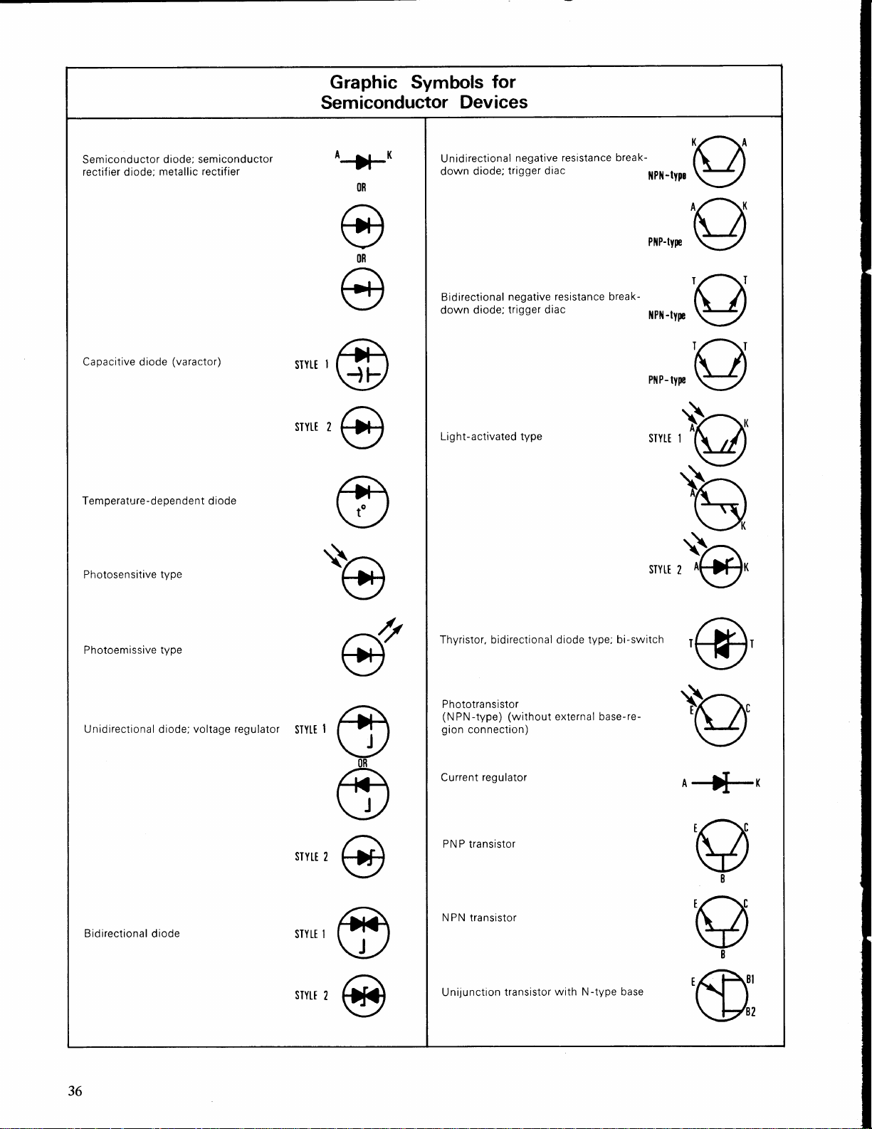
Graphic Symbols
Semiconductor
Devices
for
semiconductor
Semiconductor
rectifier diode;
Capacitive diode
Temperature-dependent d iode
Photosensitive
diode;
metallic
(varactor)
type
rectifier
A{-K
(]R
@
tlR
@
sTYrEr@
STYTE'O
O
\'^r
ry
Unidirectional
diode;
down
Bidirectional
down diode;
Light-activated type
negative
trigger
negative
trigger
resistance
diac
resistance break-
diac
break-
ilpil-typo
g
^g
PilP-type
ilpil_type
pi{p-typeg
,tr,r,@
b
$,-t
sTYrE2ou*
Photoemissive
Unidirectional
Bidirectional
diode
type
voltage regulator
diode;
a-r,
Q7
sTYr.Ero
OR
O
sTYrE2@
STYLET
o
sTYu2
@
Thyristor, bidirectional
Phototra
(N
gion
Current
PN P
N PN transistor
Unijunction
nsistor
-type)
PN
connection)
regulator
transistor
transistor
(without
diode
external base-re-
with N-type base
type; bi-switch
,@,
p
o4F
g
I
g
I
'O::
36
Page 37
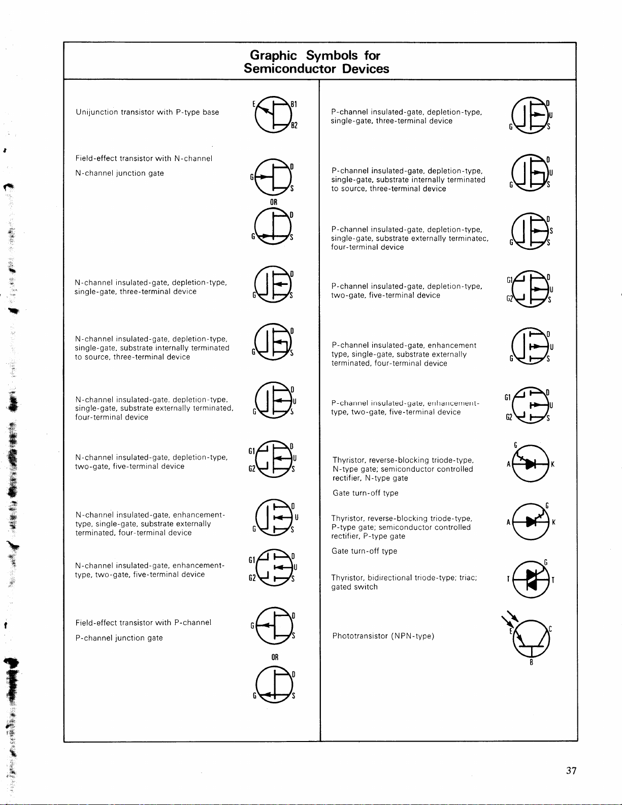
crqderg
rolcnpuocruas
qoqu^s
rol
saclneo
{hr
i.
.rW
r.l
E
,{h
.T;
*
;
#
l#
'..*.i:,.
frF
#.
ffi
.d*:
{,8
#
r@
s
.,,ffi.
q
i$.,i.'
,k,
ol
N
f"
-
;euueqc-5
l0uueqc-N
lauueqc-N
louu
pr.lc
| [J.]ra]-Jno]
louueqc-N
louueqc-[.
lauueqc-
Jolsrsuerl uorlcunftul
lco]lo-plotJ
leu
rolsrsueJl
aleJlsq
ns'a1e6-e; 0urs
nsur
palel
acrAap
leu
rullol-aArI'ele0-onnl
rur.ral-rnol'poleurura]
qlrnn
N
qtlnn
aleO uorlcunt
leurullal-aarq]'ale0-a;0urs
leuru|al-aajL,ll'ocjnos
acrAap
alerlsqns'aieO-el0urs'edAl
I
eu
leururol-oA!]'ateO-onn'adAt
eseq edAy-6
lauueqc-
'adAl-uorleldap'a1e0-patelnsur
acrAap
'edAl-uorleldap'ete0-polelnsur
uria] A1; euralur
a3rAop
A; ; euralxa alerlsqns'41e6-a10uts
acrAap
paleur
uorlepdap'ate0-
'adAl-
I ulral
'paleu
'adAl-uorla;dap'ate0-palelnsur
-luaulacueque'e1e0-palelnsur
Alleuralxe
-luauracuequa'e1e6-pelelnsut
acrlap
ol
p
a;
6u rs
tulla]
ateg
edAl-4
oleg
pate0
lauueqc-d
lauueqc-d
'a3lnos
lauueqo-d
ns'a1e0-a10urs
leuruila]-JnoJ
louueqc-d
rJ
'ate0-onnt
lauueqc-d
louueqc-d
'larlrlcal
go-urnl
'rarlrlcol
1;o-urn]
Llc]rMs
leurulla]-oatqt'ete6-e;6urs
acrnap
;
u.uo]
euralu
alerlsq ns'a1e0-
r
leutujial-aatql
alellsq
acrnop
leurural-an
alerlsqns'e1e6-e;0urs'adA1
I
eurujlol-Jno]'paleu
0ur1co;q-osranar'rolsrrAql
ate0 adAl-N
adAl
0ur1co1q-asraner'roisuAql
iolcnpuoorures :aleO
ale0 edAl-;
adAl
leuotlcaJrprq'rolstJAqI
l
A;
ocrnop
u;ral
A;1eure1xe
uorlaldap'a1e6-palelnsur
acrnap
A1;euralxa
acrAop
leulurel-anrl'e1e0-onnt'adAt
ocrnap
.rolcnpuocrr.res :aleO adAl-
'adA]-uorlaldap'age0-palelnsur
'adAl-uorleldap'a1e6-palplnsut
paleu
'edAl-uorleldap'ate0-pelelnsur
'paleur
'adAl-
lua[!acueL]ua'e1e6-pa]elnsur
-IUarrtocueLlua'e1e0-palelnsur
'edA1-eporrl
pallolluoc
'adAt-apor.rt
pallorluoc
:cerJl :odAl-opoul
'O;
'o'-'^t
j
{'
is
.
'a.
s
fr
1ff
*.
.:i:i::
**,
'i*:
'*d.f
$;
.t:
-,."q
:,w
]ca]]o-plall
lauueqc-3
uotlcunt
tllrM rolslsue.rl
eleO
l0uueL4c-d
togstsu erlolor..ld
6 5 )
(adAt- p
q
u
LT
Page 38
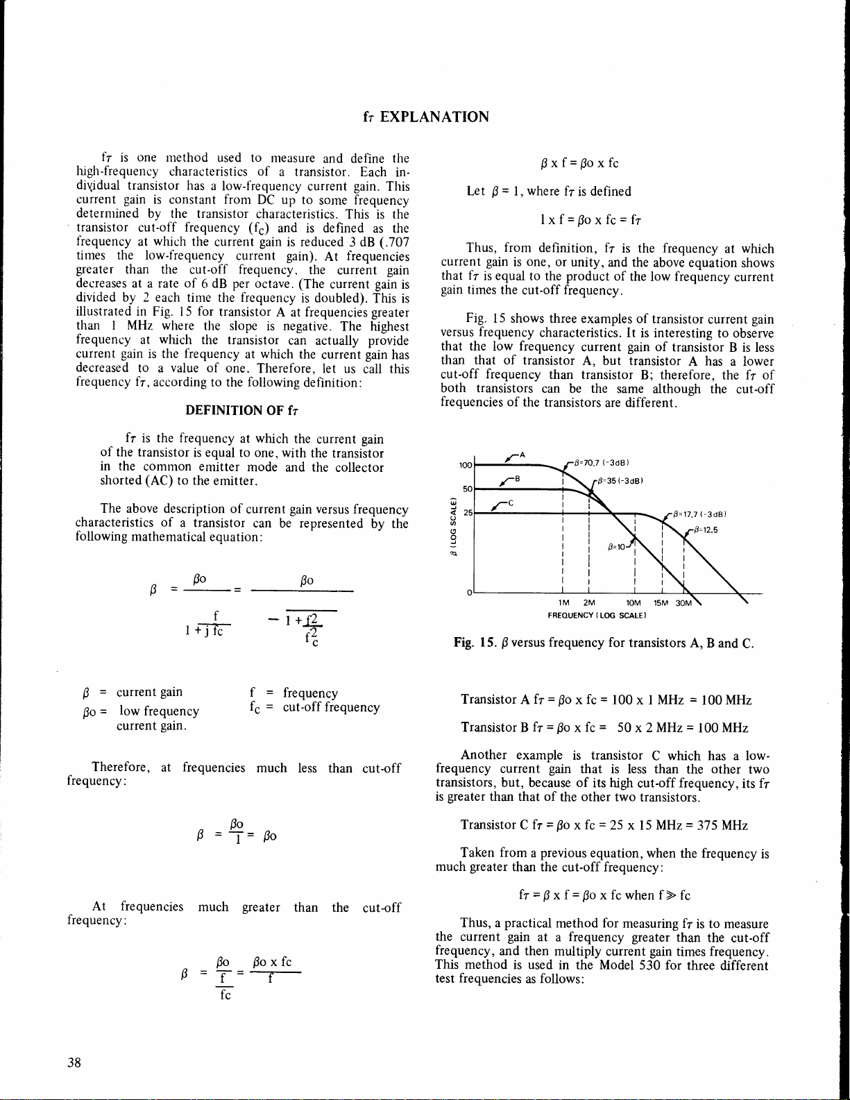
tr
one
high-frequency
diyidual
current
deternrined
transistor
frequency
tinres the low-frequency
greater
decreases
divided
illustrated
than I MHz where
frequency
current
decreased
frequency
characteristics of
following
is
gain
by 2
gain
of
the
in the
shorted
The above description
rnethod
transistor
than the
fr
characteristics
has
is constant from
by the transistor
cut-off
at
at a rate of
in Fig.
at
to
fr,
is the frequency
transistor
common emitter
mathematical
frequency (fc)
which
the
cut-off
each
tirue
l5
which
frequency
is the
value
a
according
DEFINITION
(AC)
to the
a transistor
6
for
the slope
the transistor
is equal
used
a
low-frequency
current
dB
the
transistor
of
to the
emitter.
equation :
to nleasure
of
a transistor.
DC up
characteristics.
and is defined
gain
current
frequency.
per
octave.
frequency
A at
is negative.
which
at
one.
Therefore, let
following
OF fr
which
at
one,
to
of
with
mode
current
can be
and the
and define
current
to
some
reduced
is
gain).
At
the
current
(The
current
is doubled).
frequencies
can
the
gain
The highest
actually
the
current
us
definition:
current
the transistor
collector
versus
represented
fr EXPLANATION
tl're
Each
in-
gain.
This
frequency
is the
This
as the
(.707
dB
3
frequencies
gain
gain
This is
greater
provide
gain
has
this
call
gain
frequency
by the
current
that
is
gain
versus frequency
that the
than that of
cut-off
both transistors
frequencies
U
J
(,
Thus,
fr
tirnes
Fig.
Let
P=',*Jt*;ffi:t'
lxf=poxfc=fr
from
gain
is equal
frequency
one,
is
to the product
the
cut-off
l5 shows
frequency
low
transistor
of
the transistors
definition,
or
three examples
characteristics.
than transistor
can
fr
unity,
and
frequency.
be
of
current
A, but transistor
the
are
is the frequency
the above
the
of
It is interesting
gain
B; therefore,
same
different.
equation
frequency
low
transistor
of
transistor
A has a
although the
l-3dB)
9=17.7
which
at
shows
current
current
to observe
B is less
lower
fr of
the
cut-oif
gain
=
p
current
=
low
go
current
Therefore,
frequency:
frequencies
At
frequency:
alJ
frequency
po
+-lT-
r
gain
gain.
frequencies
at
t)-
,J
f
=
P
much
Ao
f
f,
f
fc
Bo
-T=
greater
poxfc
-T--
-
-@
-
=
much
Po
po
!)
l'c
frequency
frequency
cut-off
less
than
than
the
cut-off
cut-off
15. p versus frequency
Fig.
TransistorAfr=poxfc=
TransistorB
Another example
frequency
transistors,
greater
is
much
the
frequency,
This method
test
than
Transistor C fr
Taken
greater
Thus, a
current
frequencies
fr=0o
current
but, because of
from
practical
and
gain
of
that
=po
previous
a
than
the
fr=0xf=0oxfcwhenflfc
gain
at a frequency
then
multiply
is used
follows:
as
ro,
l00x l
=
fc
x
is transistor
the
x
cut-off
method
in
the
50x2MHz
that is less than
its high
other
two
=25
fc
equation,
frequency:
for
measuring fr
current
Model
tjinrirtors
MHz
which has a low-
C
frequency,
cut-off
transistors.
x
MHz
15
when
greater
than
gain
times frequency.
530 for
A,
B and
C.
=
l00MHz
=
100MHz
other
the
=
375MHz
the frequency
is to measure
the
three
two
its
cut-off
different
fr
is
38
Page 39

I
I
i
ffi
ffi
ffi
$u
,&
,#
{ir.
,tr
d:r
w
ffi
#
ffi
#
puB
tsa;
tse;
rog
suoq
ol?JnccB
JI
00t
-0=O[Brs
I
eql
saprnord
4
00s
-0=elB3s
0
t
zHI^l
sJolsrs
puu
4
-0=opcs
I 0t
sJolsrs
pue
4
4
S? 0J? Suoll
O
-
O
-
O
-
aql
pcrlcerd
lsnru
OOI
OOS
OOSI
oql o1 e8ueqc
l?q}
:ZHIAI
1-fcuenbautsel
sr ZHIAJ
luarrnJ
uruS
sr
4
unr.uxeu u
00I
x
-'xBru
:zHI^l
t
= ,{cuenbarg
g1
sl
pesn
oql
sepr^ord qcqn
'xsru
,{cuanbar;
zHI
eql
seprlord qrlq^\
'x?ru
aq
:s/Y\olloJ
iI'IVJS
lxeu
luarrnc
e
0s
x
zHW00sI
gg
-
sr
luerrnc
0s
x
-
'suosueJ
loru
roJ
'luetuarnsBetu
ZHI^I
ZHIAI
ZHW
tuntururu
ro^\ol
'zHI4l
JoJ pesn
Jo
I
'zHI
roJ
urc3
{unuxur.u
0t
'zHl4tr
roJ pesn
4
unurxeru u
0t
qcee
aseql
'opcs
pernseeru
dn
00t
'zHW
00[
= zHhl
st
Jo 4
00S
00s
= zHhtr
sr uru8
Jo
00sl
= zH]\tr
oJB oJoq]
ur oleJs
uorloogep roler,u
01
zHW
'zHW
zHIl[
00S I
ZHIAI
runruruil.u
S
0S
00t
loutrec
qcq/r\
,tcuanbarJ-urnpo{u
-uer1
0S
ol
dn p2.tn5seru
.(cuanber3-req81q
-uer1
0S
o1
dn pernsueu
'zHIl1I
Joletu tunuruttu
ol JOpJo
r010I'U
NNIAIINIIAI
ZHW
zI,{H
zHW
oq
sJolsrsusJl ,{cuenberJ-A\ol
001
-c0u0p
uu aprlord
-couep
'paumlqo
(t
I
I
m
=
o
f,
o
-{
m
?-
r
I
m
ar(
raleruurud
'suorlBc
lJ
u
po^lo^ur
Surpuar
alenlule
,{puruy
Surluredo
ot
eq
plnoqs
uuc srelaurerud
0z
'9I 'EIC
Surrnseau
e8ueqc
fcernccu
lou
seop srelauured
ol
oq
soJr^ep
01 ocueraJou'suor}
'8lc
uorler.uJoJur
er{l'uorleuro3ur
eq uec sJolsrsusJl
09
]u?lsuoJ
e8ellorr
's,r
eql uFlll^\ sonp^
l?q}
poraquouor
puB
tJ
erlt
rg
salldde
,{1uo
leql
wotu
s^{oqs
gl
eql
'umorp
eq uur suorlrpuoc
olrl?ler
'peurur0l0p
0t
0z
UOtC:ttOC-31
4
sa^rnc
rolcelloo
'(srolsrsuerl
,tcerncce
eroql
leqt
'Supeer
le
]sol
aql
repun pesn
leq}
'pelcrpard
luerrno
or{t
pel?ts
q
ore
eqg
eql
louuuc
eq
Jo
esn
,{q
ecuewro;red
ue^E
001 09
Vtu-lN:lUUn3
nlodrq)
-r3rceds
solqurru^,{ueu
lsel
oql ut se8uuqc
4
tetll tcuJ
eql
lset
pargrceds
ol
pesn
Eurleredo rer{lo
-IpuoJ
erll
o^rnc
w
Jotllo
lnoqlr^\
sql
Jo
ecuuuro;red,(cuenber;-q8q
oog
rellttuo-rolcolloo roJ
ffi
$
#
.f
ffi
$
V
g
sHtr
serq
gES
u?
sV
aqt
rteldsrp
rolslsrrB{
'snq1,
runuru[u
aq1 3un6
}ue}rodur
u?
sepmord
esneceq
'luorJnc
e8ellol
0I
pu? sllo^
'oroJereql
ogl
onp^ o}nlosqu
lseluar8
0q1 ocurs
.,{ueru
sllo^
? sept,rord
eql
eq}
'alduexo
00I-0
IL
s7, 3
lsotu
pouwlqo
uor]Jeuep Jolel,u
'onlu^.lg
rolselloc
solqulre^
serq crl?ruoln?
pu8rs
elduexa uV
uI u^\oqs st
lsoru
roJ
8 l?tmuou
pernsBel.u
00s-0
00I 0S
jsz
olurncJu
tuory
.{ue
senF^
sBrq
Jo
0I
srolsrsuurl
4 Jo
'91 '8lC
4
s11o^
enlB^
srolsrsuerl eerr{l
00I 00I
00I
sLt,
enlu^
roJ
epcs
aru
luerrnc
sr
Euruturalep roJ
'4
JoJ
etu
opllord
lIJn
s
lICn
4 Jo
ur
:elucs rlcue uo Surpuar Surnogo3
4
roJ
SI
'8ld
00sI-0
ou)
(pooE
ou)
(poo8
oql
sl
peptnord
uo
popoecxe
Jo
Ouo
eql
Oql
o{t
Iopow
Jolcoiloc
lsoq8q
Jolcolloo snsJel
,{1ensn
eqJ
'sluel.uornsseru
$
p[u^ sl
plno^\
rI
00r
00r
SLE
lse8rel
l?q}
oql
0[3cs 0q]
lsol'u
gss
'luerrnc
w
t!
lueJrnc
pu?
S
uoe^Ueq
Iepow
Supnwor.u
'-ry
osaql
6E
Page 40

WARRANTY SERVICE
INSTRUCTIONS
Refer
1.
2.
3. lf
If
your
to the
adjustments
Defgctive parts
period.
should
state the model
date the
terms
of
the
above-mentioned
your
with
Enclose
or ship
agency
your
a letter
PREPAID
(see
list of authorized B & K-Precision
local
distributor for
MAINTENANCE
may
that
was
unit
Warranty.
the
unit,
list enclosed with unit).
be applicable.
removed
be sent
and serial number
pack
describing the
from units which are within the One
PREPAID
purchased.
procedures
it securely
([IPS
preferred)
name
the
B &
DYNASCAN
2815
your
section of
to the
of the
parts
These
not
do
(preferably
problem
of
Service Deportment
K-Precision Product
Chicago, Illinois 60618
and
the
to
your
CORPORATION
West
Irving
B & K-Precision
Service Department
unit from which the
will
service
nearest service agency,
exchanged
be
correct
in the original
include
nearest B &
agencies
Group
Park Road
instruction
Year
listed below.
parts
at
problem you
the
your
carton
name and address.
K-Precision
has
been
or write to:
manual for
Limited
were removed and
no
charge,
or
authorized
misplaced,
Warranty
Be
under the
experiencing
are
double-packed).
Deliver
sure to
to,
service
contact
40
Page 41

I
*
$
i
,-l'
:?l
$N
:l
#{
.r.
$
lcnpord
Jo
elsp or{} ruor3
11
.,{ue
seluls etuos
futu uotsnloxe ro uorlulnul e^oqe eq] os
lrun
g pezrroq}ne
st
op
pue
}Jeluoc
ol
eql ol
ee{ aq
ro nedar
oiup oql
'NVJSVNAC
eql u! {1dde
lou
lou
eq] o] no{ reJer u8c Jo
g
UVAA-ENO
uor3
lp
'eceldar
Jo
}sntu
g
plo^
rno,i
aq
?
'eseqcrnd
Jo
lua^e
J!
aql
leyluanbesuoc
,/r\olp
o1 fldde
,{eu no{
g
lsaJuou
pro^e ot pe8elced
eseqcrnd
osl€
(IAIIHII'I
NVf,SVNAA
eq1
pue
'lcnpord
u
ecnres
srouql
llnser
eluls
01
louuuc
go porred
lueuoduroc
pesolruo
Jo
'pa^oruer
se8euep
'sa8uuep
srq;
rog
pozuoq}nE
eq
ure}qo oI
99909
'elEls
rno{
o}
ruaf euo
NVf,SVNAC
'luetulredep
ftuurrsln
:suorsnpxg
Suqlnser
peurc]qo
luauoduroc
tuor;
'ru/\{
,{luerrern
S)
o^U urqlkr\
slrll
pezrJoqlnsun
II€r{s NVf,SVNA61
ssol uorj
salt8
{luerrern
srreder e{Bu
'f1pco1
srouqll'o8ecrq3'peo1
NOIIVUOdUOJ
slred
Jo
el?p oql
lnoqlp\
ue ot {renrlep uodn slred
fq
peueduocce
'eSuranoc
uorlerlsder
preo
(sfsp
,$uerru,n
}ou
Jo
'asn
o/r\ ccuoruo^uoc
esuald
sluerre^\
ru/t\
'JoeJeql
'esuqcrnd
'e8reqc
Jo
goord
srq}
ol
lou
saop
ro suorluJalle
'srndal
olqet1 eq
roJ
slq8u crjrceds no{
1se33ns
nof
aq]
pues
{pedord'8I909
AINVUUVM
reseqcrnd put8uo
uI slJeJep
sll
NOISIf,:IUd-X T
ectnres
ul
,{q
paralst8ar
asnslu
IBIras
'se8eurup
Jo
uorlclnuq
'nof
o^eq
eJrAJes
NOISIJaUd-) ?
ut e8euep
leql
stl
g
dtqsueulrol\
'uorldo
Jo
uJoJ eq]
e
'O'd 'NOISIJSUd-)
Jo
asnqu ro
sI
Joqunu
Surpnlcur
slq8tr raqlo
NOISlf,ggd-) 1
ll
'ro}J[J]uoJ
'luotudrqs
pue
e^rlcoJop
ro ro}cer}uo3
seps
'ldtecer
Sutlalduoc
puu
xog
'080S8
aql
Ielueprcur
sISZ'arl^res
lcnpord
'paralp
]noqtl^\
Jo
,{ren qclq,ttr
'JolllqlJ}slp
tsc^\
NOISIJSUd-) ?
slulJeluu
roJ
lcnpord
ro
Aroice; er{l
eq] Suureru
'o3ectq3
s ss ro
ro
pacqap
uorlulnurl
lutluanbasuoc
utorg
aq ,(uut oq,tr
aJIAras ,{luurre,,n
Vu6
3unr1
Page 42

NVf,SVNAq
NO|lVUOdUOf,
I00-6-902{8t
09t9
'rVl
-':{|q6':J"
-
,o6?rj.{f,*.
'l
sloullll
PuDluoJ
teerls
98909
Page 43

B
& K.PRECISION
MODEL
488-195-9-OO3
530 PAR.TS
LIST
SCHEMATIC
SYMBOL
R85
R79
R83,
81
Rl21
R101,
55
R22,97
R72
R92,
106
R56,59
RI03,58
c44
c42
c39,39,40,41
c20',25
c56,
57
,47,
50,49
c56,46
c43
L1
L2
L3
DESCRIPTION
RESISTORS
g-lKo,
!2%,r/qw,
y2%,y;W,
L3Ko,
!2%,y4W,
18KO,
199_KO,. ?0%, /eW,Horizontal
qg!{o,
$9Vo,laW,Horizontal
lg$sffl, P9Vo,
30Ksl,
I_0_0KQ,- P.0
?!ta,P0_V9,lcW,Honzontal
IKdl,,!20%,/cW,Horizontal
W,
+\07o,r/zW,Linear
7.o'_!:Y,
& CONTROIS
Deposited
Deposited
Deposited
Hotizontal
C:rbon
Horizontal
CAPACITORS
@I,iOVDC
lQy.f
l9Q{r@_10VDC
@25VDC
1Q09qr
47p,t@6.3vDcTantalum.orur
|
250vDc
@
.9474@?J0V
.|pt@l00VPolyester..
Electrolytic
Electrolytic
Electrolytic
polyester
Polyester
coIIs
Oscillator,
Oscillator,
Oscillator,30MHz
I
MHz
lg
MHz
Carbon
Carbon
C:rbon
Mount
Mount
Mount
Pot . .
Mount
Mount
Mount
Linear
Trimpot
Linear
Trimpbt . .009-224-i{0
Linear
Trimirot .
Linear
Linear
Linear
.....
Trimpot .
Trimpot
Trimiot .
B&K
PART NO.
002-039-9{0
002{40-9{0
002{41-9{0
.
008-2
1 6-9-00
.
008-241-9-00
.
.008-301-9{0
008-286-9{0
. . .
00g-297-9-00
. .008-289-9{0
.
021{40-9{01
.
022{50_t{0i
022084-ri0r
...027-013-9{01
.
.025427-9-001
....025-096-9{01
....025-I2O-gOOi
....044-035-9{01
. .
.044{36-t{0i
...044{39-g{Oi
coltrPosrrE
499-n4-9-ml
Page 44

MODEL
530
PARTS
UST
SCTIEMATIC
SYMBOL
Dl4,
15,
16,
r7,24,25
D19,20,21,22,
23,3I,33,34,
35,
1,2,3,
13,18,32
8D4,5,6,7rL0,
It,27,28,30
D9,
10
D12,26
Q9,10,
Ir,12
Q4,5
2,
3,14,
Ql,
17,18,19,
22,24,29
Q13,20,21,23,
25,26,27,
28, 16
Qls
IC1, IC6, ICg,
rc3
ICl0
lc2,rc4,Ic7,Icg
IC5
DESCRIPIION
DIODES
IN695,GermaniumDiode
l
IN4148,
Rectifier
l
5.1V,
{Vo,IW Zener
l2V,!5%,1W
2N5550
MPS
2369 NPN
MPS
6515 NPN
MPS
6519 PNP Transistor
)
SPS-2306
AND
Silicon
Diode
Diode
Zener
NPNTransistor
Transistor
Transistor
NPNTransistor.
INTEGRATED
LM324,
4013,
4011,
40z3,Triple
Quad
Dud
Quad
OP-Amp
D Flip-Flop
2Input
Nand
3Input
TRANSISTORS
Diode
Diode
.
.
CIRCI,IITS
Gate
Nand
Gate
B&K
PART
NO.
...150{02-9{01
.
151-038-9{01
.
151{50-9{01
.
152-030-9-001
. .
152{39-9{01
....176133-9{01
. . tZ6{49-9O01
. .
126-050-9{01
. . .
t77-OtS-9-001
...t76{.29-9-001
307-060-9{01
307-062-9{01
. . . .
307-063-9-001
...307470-9{01
S9
s4
S1
s3
S8
s2
s6
s7
S5
SWITCHES
Iradldentification,hver
Spring Return,
fr
Range,
SPDT,
DPDT,
DPDT,
i$|T:
Momentary4-Pole,Push-Button
Rotary
.
MHz
(Speaker
Slide
(Power
Slide
PC
33!il$!
(Drive
Slide,
S'*l/H'*,' : : : :
ON/OFF)
ON/OFF)
LO/HI)
: : . : : :
....080{02-9401
. . .084-001-9{01
. . . .084{01-9{03
. . . .
: : : : : : :
:1084{4se{01
...088-029-9-001
.083-195-9-001
.083-205-9{01
084{43-9-001
Page 45

ots
IlI(Ion
sf,rtvd
rsI'I
I-'Id
Ic
II
IJ,
In[
ZTN
JI.IVNgHJS
l0sn^s
r-urds
z-(JitrI'I{aT
,esng
reaod
reaod
'u1Cg
pal{Dls
NeI
enlg
uearg
^roile1
durl uoep
g/1
,dury
IepI^[rJ
""
u3're4uedg,,g
rlclFt\s re^e.I
r
qoux par+ls
r?g
sde3 rouqg
elqeJ
p?e.I
susueg
Busuug
stteu?g
proJeun
aroJalFrac
rolsrsuurl
NOtrdrulsl!rc
U)00I//t\
,ASSU
urt'etu1er1
qoux
qll
qoux
qlFr\
IcBlg.uollngqclFtrs
Ic?f
Icsf
{c?f
....dlqSluuturel
rolsrca1
/troIB-oIS
z609,L07l.raruro;suer;
relel4l
"""':
ralulod
rslulod
flqutassv
' '
flquassy tn14
SdXIY'I UOIYCICNI
Hld/dNd'HlN/NdN'cgTpeu
"'
'
S{IOIItrnn'IICSIRI
I1el8td
'
' '
..
4t0g/0s,L0vzlozl.reruroJsuur;
. .
. . . .
" "
'
'
' '
' ' '
"'
"'
:::::::::::::::::,a{cos'o}srsu?rr
'
'
' '
' '
' '
x?g
ruvd
'oN
I0&5-ZI08SI
20gr,6-I96rl0t''
006-110€6I
0O6-3II-590'
ou6-6cl-gg0
006-9ro0ce"'
OU6-LLV0C€
006-S0008S"'
0&6-8II-IS/,
0G6-g€I-IS L'
006-6€I-IS L'
0G6-€I0F?8€
006-SI0t8€
3ffflrf?t
€00-6-I00?LL'
t006-I0OtLL'
9005-I0et LL'
I006-0I&0(,t...
I00.6-c0D01g'..
I006-9UgrStE"'
I0Gd-8rI-€(,5'
Page 46

NOTE:
Standard value
schematic
previous
Advance
ordering
B
diagram.
open
remittance
replacement
& K-PRECISION.
Minimum
account
must cover
parts.
resistors
and capacitors
charge
arrangements
postage
DYNAIrcAN
$5.00
have
CORP.
are
per
invoice.
been
or
express
o
646014r.
listed.
not
Orders
made
charges.
Cortland
Values
will
or remittance
b€
Specify serial
o
St.
616*,
may be obtained
shipped
C.O.D. unless
accompanies
number
Illinois
60035
from
order.
when
Page 47

l-;l
t>l
tEl
L:.1
ox
;i
Or
6
=
d
@
t
I Fl
lql
tlj
3
|
'l
t3l
tEl
I 'llzl
EI
LEJ,P4
VY
vtv
YI\/
laol
L-/s-{<v$-J
33 33
P
qP
EJ
+
Fil
lEis
e
Eq
Fi;l€l
r
-
-T1
Qx\
h-8.-{
6El
;t
!t!t Et;
-1 :l
i
*lf-'
38
+
FX
sx
cd
3E
l=l
lal
L:J
|.;I
t=l
lrl
tol
al
tG I
IUI
tYl
t< i
IU I
tc I
b5t
[il
s
tl.-r
rl^
N(9
t
I
|
t'
I
inrJ wlcl!
;l
::
Et
i
!
----;-i
t.(u,
illll;
t!.rJ
,
frrn |rrn i
=;l
t--t
t't6l
a:i
s|
| x I
h_s_rl
tjl
t-l
tdl
Aa
Iff
ls
E-.
ooi
i
I
I
9
a
+
a,
o;
a'
!
t
\
I
bc
E9
@
o,
=
D
.T
I
F
a
EN
L:J
E exl
e,
!0
,r-1F-'r
i
Est
sL6
l,rFN----
c
o
;:
=>?6
l4
F
(?)G
e
I
I
I
o
l
In ;t/t
E=
\
o
Page 48

EI
EJ
{o
lq
gt
-@
bo
!t
'{o
:t
6q
a!
i6
oo
:t
5@
'rH
gl
5'
;.
3
!
{lC-to
d3
T
5t
9r
r8
g3
o
o-t goo
:d
63
oo
a
l6
E3
o- x
o=
o
5s
It
xa
-6
Tg
j
b9
-U
gt
fts
;c
2a
i1
IOoT
1
E;
;
o
:o
YE
I
ci
be
l-:-l
=t
t t-*t
eI
lF-)F--r
,rH
q
€
{
!o
o€q:6r
@@nIz
icq
l-r
Aa
r^{
a6z
!i
Ezz
o
-J<
l!l
Al=J
e-t)-->
I
l**---k
Eg
;d+ I
,a
16
oa
FE
t3
c4z
2ra
EA-
oE
sE?
{H
qg
i
n
o!
dg
e8
.o
oq
{Hl-
I
.IHF
b8
{H
tr8
li:
e
!
,rr-
V
39n
2>=
8dg
3i
c
>=4
@==
a2z
tol
tcl
lrl
r;l
l{l
I
A
I
rh
z
:o>
691
;o-
.=l
9:r
az-
oI2
!F
e
e=F
E9{
'l
lol
I,I
tol
=lql
tl
tet I
5
p
3ei
r69
E
@
tcl
lfl
U
I
\'
'o
qiE
I
L@
{.
Ees
FS
oB
90
4Z
,
*g
3
n
-
oni
=1
rrX
i8
o
z
FI
o
€=.i
:a,
<62
w
i\z
rc
LA
RI
lql
K
XE
Yl.i
N
q
K
R
o
-@6t
2
z
a
=
-
lsl
K
 Loading...