

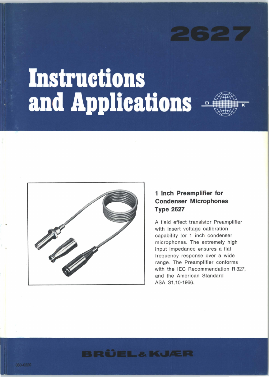
1 Inch Preamplifier for
Condenser Microphones
Type 2627
A field
with insert voltage calibration
with the
effect
transistor Preamplifier
capability
microphones. The
input impedance ensures a
frequency response over a wide
range. The
and the American Standard
ASA 81.10-1966.
for
1 inch condenser
extremely high
flat
Preamplifier conforms
IEC Recommendation R
327,

MICROPHONE PREAMPLI Fl
TYPE 2627
ER
September 1971

CONTENTS
1.
INTRODUCTION
1.
1.
Genera I . . . . . . . . . . . . . . . . . . . . . . . . . . . . . . . . . . . . 5
Preamplifier Requirements . . . . . . . . . . . . . . . . . . . . . 5
1.2.
2.
DESCRIPTION . . . . . . . . . . . . . . . . . . . . . . . . . . . . . . . . . . . . . . . 8
2.
1.
General . . . . . . . . . . . . . . . . . . . . . . . . . . . . . . . . . . . . 8
2.2. Characteristics
Input
Output
Frequency
Attenuation
Distortion
Noise
2.3.
Environmental Sensitivity
Temperature
Hu!Jlidity
Vibration
Acoustic Sensitivity . . . . . . . . . . . . . . . . . . . . . . . . . . 16
Magnetic
Shock Sensitivity . . . . . . . . . . . . . . . . . . . . . . . . . . . . 16
. . . . . . . . . . . . . . . . . . . . . . . . . . . . . . . . . . . . . 5
................
;
...........
Characteristics . . . . . . . . . . . . . . . . . . . . . . . . . .
Characteristics
Response
........................
..........................
. . . . . . . . . . . . . . . . . . . . . . . . . . . . . . . . 14
..................................
..................
.
..................
......................
................................
..................................
..................................
Field . . . . . . . . . . . . . . . . . . . . . . . . . . . . . . 16
~
.
11
11
12
13
14
14
15
15
15
15
3.
INSERT
VOLTAGE
3.
1.
General . . . . . . . . . . . . . . . . . . . . . . . . . . . . . . . . . . . . 17
Principle
3.2.
Use
with
Calibration
Insert Voltage Junction Box ZH 0007
3.3. System Calibration
CALIBRATION
of
The Insert Voltage Method
8 & K equipment
Facility
......................
with
...........................
...........................
...........
Insert Voltage
............
17
17
18
21
23

4.
USE
WITH OTHER EQUIPMENT
........................
24
5.
SPECIFICATIONS
4.1. Microphones
Accelerometers . . . . . . . . . . . . . . . . . . . . . . . . . . . . . . 25
4.2.
4.3. Microphone Power Supplies
4.4. Extension Cables
................................
....................
............................
....................................
5.1. 2627 Preamplifier
5.2.
Junction Box ZH 0007
............................
........................
24
25
26
27
27
28
1.
INTRODUCTION
1.1.
GENERAL
The
Type
2627 Preamplifier
& K Condenser Microphone Cartridges
B
features the capability
Preamplifier may also
impedance
B
& K Measuring
is
required. The Preamplifier may
for
be
Amplifiers
is
especially designed
calibration using the insert voltage method. The
used
when impedance matching
and Analyzers,
Power Supplies.
The
input
configuration
of
the Preamplifier
Recommendation R-237.
Type
be
or
from
for
use
with
the 1 inch
4144, 4145,
powered
and
from
high
directly
the B & K Microphone
is
in accordance
4146.
to
from
with
It
low
the
IEC
PREAMPLIFIER
1.2.
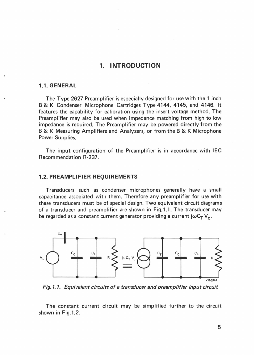
Transducers
capacitance associated
these transducers must
of
a transducer and preamp I ifier
be
regarded
as
a constant current generator providing a current
REQUIREMENTS
such
as
with
be
Fig.1.1. Equivalent circuits
The constant current
shown in Fig.1.2.
condenser microphones generally
them. Therefore any preamplifier
of
special design.
are
R
of
a transducer
circuit
may
Two
equivalent
shown in Fig. 1.1.
and
preamplifier
be
simplified
The
further
have
a small
for
use
with
circuit
diagrams
transducer may
the
.
V
0
R
circuit
circuit
jwCr
input
to
5
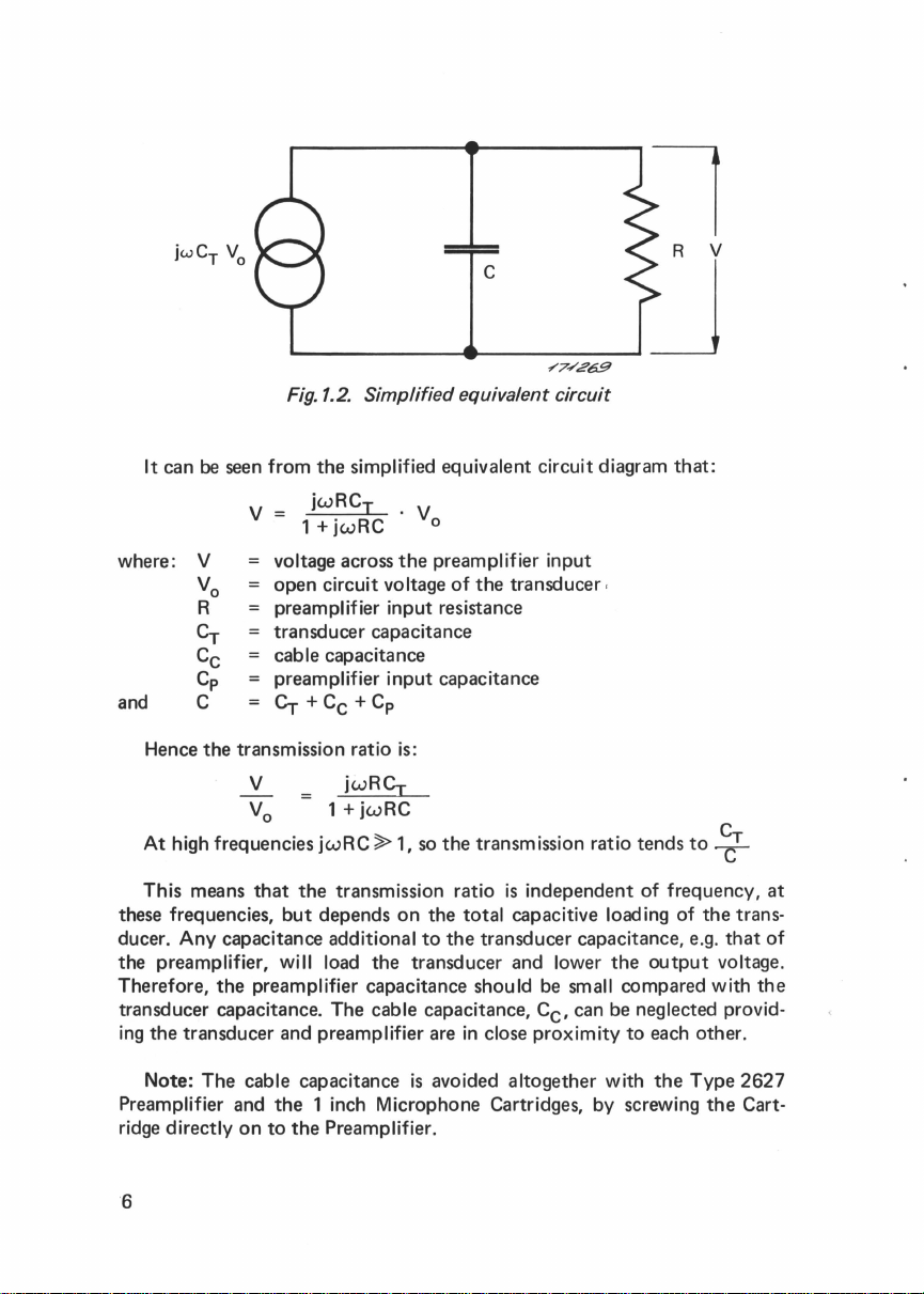
It can
be
Fig.1.2. Simplified equivalent circuit
seen
from
the
simplified equivalent circuit diagram
c
.,....7....-'£69
that:
v
where: V
vo
R
Cr
Cc
Cp
and
these frequencies,
ducer.
the
Therefore,
transducer
ing
Preamplifier
ridge
C
Hence
the
transmission ratio is:
V
V
0
At
high frequencies
This
means
that
Any
capacitance additional
preamplifier, will load
the
preamplifier capacitance
capacitance.
the
transducer
Note:
The
cable capacitance
and
directly
on
to
jwRCI
1 +
jwRC
voltage across
open
circuit voltage
preamplifier
transducer
cable capacitance
preamplifier
Cr
+
Cc
1+jwRC
jwRC
the
transmission ratio
but
depends
The
and
preamplifier are
the
1 inch Microphone Cartridges, by screwing
the
Preamplifier.
. V
0
the
preamplifier input
of
input
resistance
capacitance
input
capacitance
+ Cp
jwRCr
~
1, so
the
on
the
total
to
the
the
transducer
cable capacitance,
in
is
avoided
the
transducer
transmission ratio
is
independent
capacitive loading
transducer
and lower
should
Cc,
close
proximity
altogether
,
capacitance, e.g.
be small
can be neglected provid-
with
tends
of
frequency,
the
output
compared
to
each
the
to~
of
the
trans-
that
voltage.
with
other.
Type
2627
the
Cart-
at
of
the
6
Now, if
jwRC~
gain
off
1.
of 6 dB
The
cut-off
frequency,
the
response
So
the
transmission ratio
per
octave
frequency
f, = 1/(27TRC).
at
low frequencies is considered, it can be seen
tends
to
(20
dB
(-3
per
decade) as
dB
point)
is
where
jwRCr.
the
This
frequency
wRC
= 1. Hence
gives a
decreases.
drop
the
that
in
cut-
A lower
capacitance,
transducer.
preamplifier
quired.
cut-off
C.
Therefore
to
frequency
However, this
it
be as high as possible, if a low
could
would
is
necessary for
be
obtained
reduce
the
by
the
signa I
input
frequency
increasing
output
resistance, R, of
the
from
response
total
the
the
is
re-
7
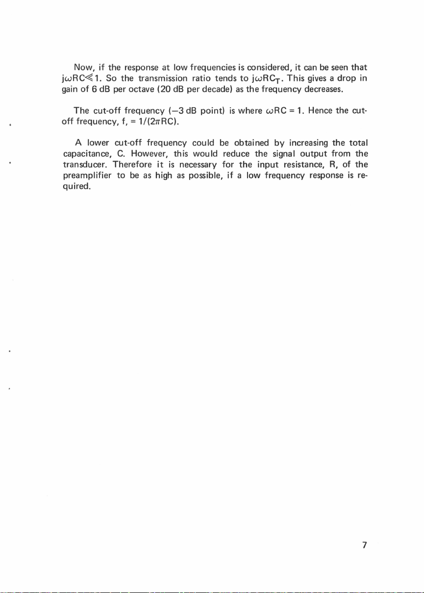
2.1. GENERAL
The
Type
2627 Preamplifier
tains the
and
for
Preamplifier,
a small screwdriver
storage
of
a B & K microphone cartridge in its
2.
DESCRIPTION
an
Input
OA
0001. Provision
is
supplied in a mahogany
Adapter
JJ
2612
is
made in
for
own
case
which con-
a B & K plug
the
Preamplifier
case,
see
Fig.2.1.
JP
0101,
case
1.
The
Fig.2.
The physical dimensions
a B & K 1 inch microphone cartridge,
is
fitted
with
Microphone plug
Preamplifier Type
of
the preamplifier alone, and when
a 2 metre long cable, which
JP
0701,
see
Figs.2.2
8
2627
and mahogany
are
shown in Fig.2.2. The preamplifier
is
terminated in a B & K 7
and
2.3.
case
fitted
with
pin
 Loading...