

Page 1

CAST IRON
SINGLE PHASE
S1500C-F
316 STAINLESS STEEL
SINGLE PHASE
SX750CSS-F
SX1500CSS-F
INSTALLATION, OPERATION & MAINTENANCE MANUAL
FARHENHEIT
™
S-F& SX-F SERIES
SIDE DISCHARGE
Electric Submersible Pumps
Single Phase
115V & 230V
Read this manual carefully before installing, operating or servicing these pump models.
Observe all safety information. Failure to comply with instructions may result in personal
injury and/or property damage. Please retain these instructions.
Version 2/12/2014
Page 2

Page 3

TABLE OF CONTENTS
INTRODUCTION ........................................................................................................................................... 4
SAFETY ........................................................................................................................................................ 5
INSPECTION ................................................................................................................................................ 6
PRE-INSTALLATION INSPECTION ........................................................................................................ 6
OIL FILL QUANTITY/TYPE ...................................................................................................................... 6
PUMP INSTALLATION ............................................................................................................................. 7
POSITIONING THE PUMP ....................................................................................................................... 7
PUMP ROTATION .................................................................................................................................... 8
TYPICAL MANUAL WASTEWATER INSTALLATION ................................................................................. 9
TYPICAL AUTOMATIC WASTEWATER INSTALLATION ......................................................................... 10
STOPPING ............................................................................................................................................. 10
CONTROL PANELS CONNECTION OPTIONS ......................................................................................... 10
OPTIONAL FLOAT CONNECTION ........................................................................................................ 12
TROUBLE SHOOTING ............................................................................................................................... 12
PUMP WILL NOT RUN ........................................................................................................................... 12
PUMP RUNS BUT DOES NOT DELIVER RATED CAPACITY ............................................................. 13
SERVICING YOUR SUBMERSIBLE PUMP .......................................................................................... 13
MAINTAINING YOUR PUMP ................................................................................................................. 13
CHANGING SEAL OIL ........................................................................................................................... 13
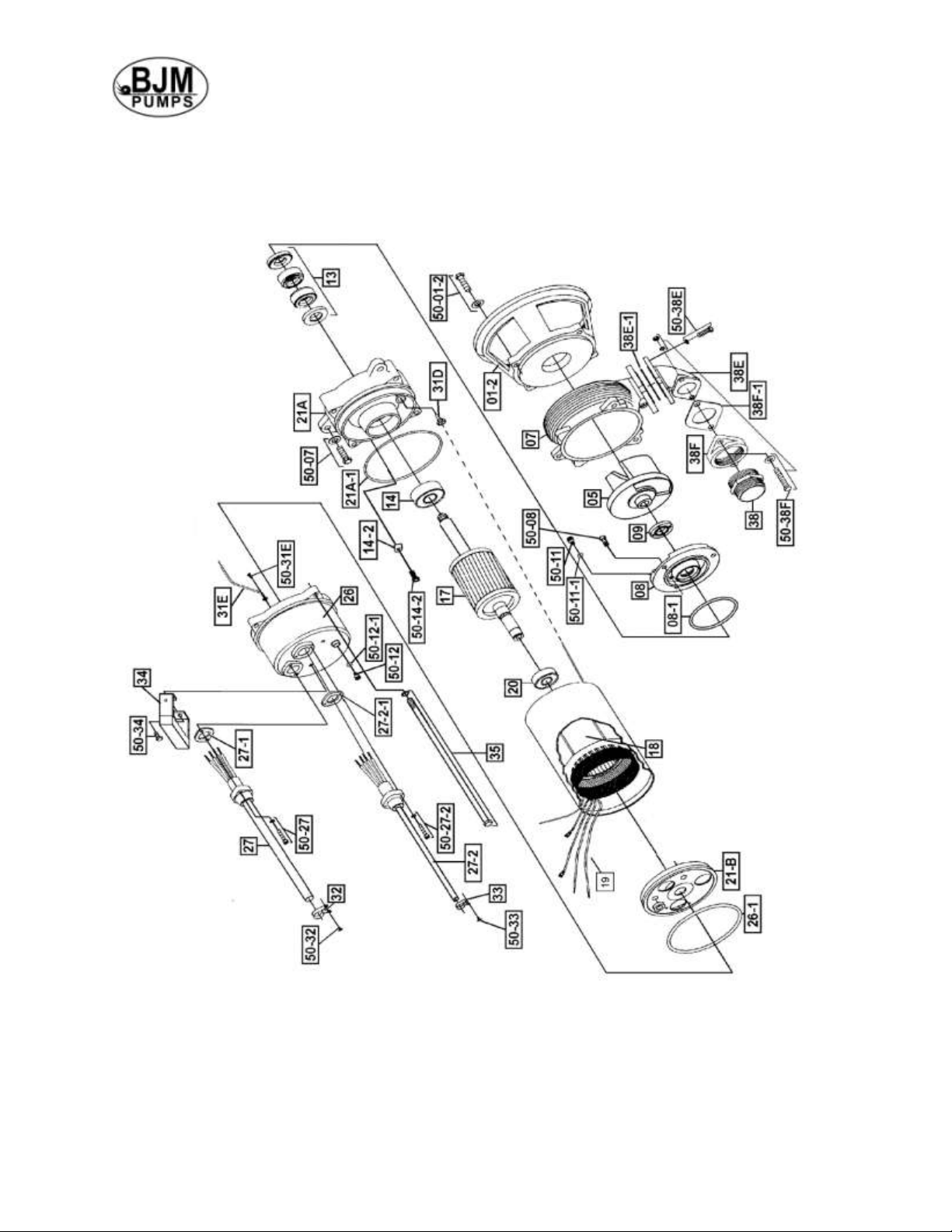
EXPLODED VIEW OF S1500C-F ............................................................................................................... 15
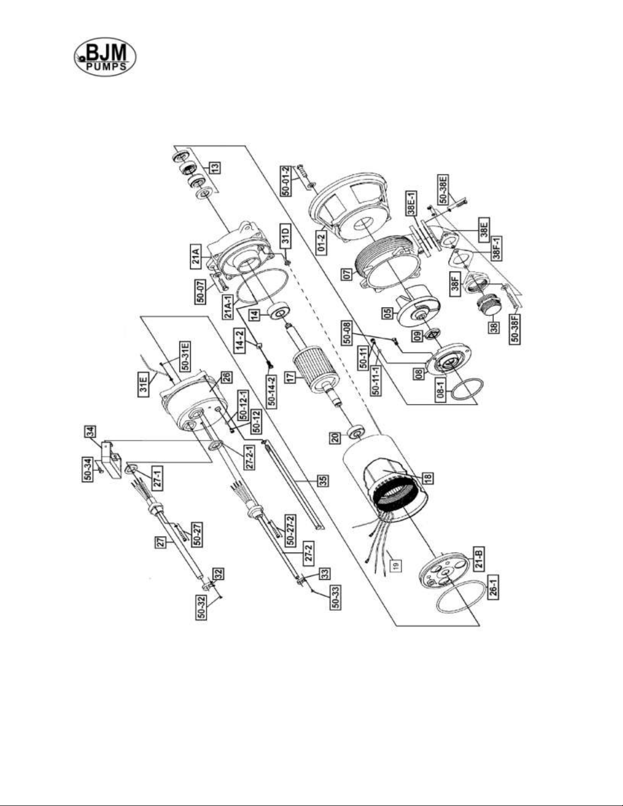
EXPLODED VIEW OF SX750CSS-F AND SX1500CSS-F ........................................................................ 16
S-F SERIES PARTS LIST ........................................................................................................................... 17
SX-F SERIES PARTS LIST ........................................................................................................................ 18
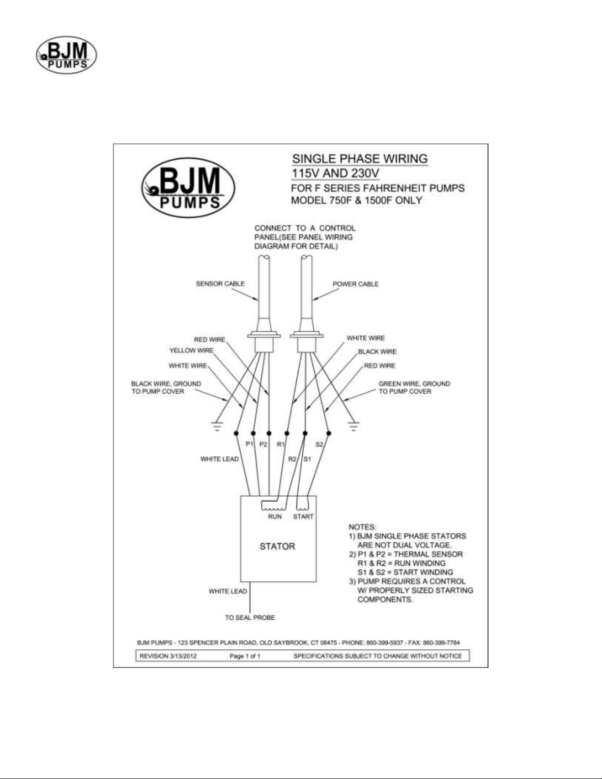
SINGLE PHASE WIRING DIAGRAM ......................................................................................................... 19
115V & 230V ........................................................................................................................................... 19
MODELS S1500CF, SX750CSSF & SX1500CSSF ........................................................................... 19
SEAL MINDER® - THERMAL MOTOR SENSOR SWITCH ....................................................................... 20
WARRANTY AND LIMITATION OF LIABILITY .......................................................................................... 21
START-UP REPORT FORM ....................................................................................................................... 22
NOTES: ....................................................................................................................................................... 25
Page 4
4
INTRODUCTION
This Installation, Operation and Maintenance manual provides important information on
safety and the proper inspection, disassembly, assembly and testing of the BJM
Pumps® S-F & SX-F Series submersible pump. This manual also contains information
to optimize performance and longevity of your BJM Pumps submersible pump. The F
Series FARHRENHEIT™ pumps are engineered to pump water based liquids up to 200°
Fahrenheit (93°C).
The submersible S-F Series pumps are designed to pump water and wastewater.
The SX-F Series pumps are designed to pump corrosive liquids in concentrations
chemically compatible with 316SS and FKM. The S-F & SX-F Series pumps are not
explosion-proof. They are not designed to pump volatile or flammable liquids.
Note: Consult a chemical resistance chart for compatibility between pump
materials and liquid before operating pump. Consult BJM engineering if there is a
question on chemical compatibility.
If you have any questions regarding the inspection, disassembly, assembly or testing
please contact your BJM Pumps distributor, or BJM Pumps, LLC.
BJM Pumps, LLC
123 Spencer Plain Rd
Old Saybrook, CT 06475, USA
Phone: 877-256-7867
Phone: 860-399-5937
Fax: 860-399-7784
Information, including pump data sheets and performance curves, is also available on
our web site: www.bjmpumps.com
For assistance with your electric power source, please contact a certified electrician.
Please pay attention to the following alert notifications. They are used to notify
operators and maintenance personnel to pay special attention to procedures, to avoid
causing damage to the equipment, and to avoid situations that could be dangerous to
personnel.
NOTE: Instructions to aid in installation, operation, and maintenance or which
clarify a procedure.
Immediate hazards that WILL result in severe personal injury or
death. These instructions describe the procedure required and the injury which will
result from failure to follow the procedure.
Hazards or unsafe practices that COULD result in severe personal
injury or death. These instructions describe the procedure required, and the injury which
could result from failure to follow the procedure.
Page 5
5
Hazards or unsafe practices which COULD result in personal injury
or product or property damage. These instructions describe the procedure required and
the possible damage which could result from failure to follow the procedure.
SAFETY
Pump installations are seldom identical. Each installation and application can vary due
to many different factors. It is the owner/service mechanics responsibility to repair,
service, and test to ensure that the pump integrity is not compromised according to this
manual.
Risk of electric shock – this pump has not been investigated for use
in swimming pool areas.
Do not pump flammable or volatile liquids. Death or serious
injury will result.
Before attempting to open or service the pump:
1) Familiarize yourself with this manual.
2) Unplug or disconnect the pump power cable to ensure that the pump will remain
inoperative.
3) Allow the pump to cool if overheated.
Do not operate the pump with a worn or damaged electric power
cable. Death or serious injury could occur.
Never attempt to alter the length or repair any power cable with a
splice. The pump motor and pump motor and cable must be completely waterproof.
Damage to the pump or personal injury may result from alterations.
After the pump has been installed, make sure that the pump and all
piping are secure before operation.
Do not lift the pump by the power cable piping or discharge hose.
Attach proper lifting equipment to the lifting handle (or lifting rings) fitted to the pump. Do
not suspend the pump by the power cable.
Obtain the services of a qualified electrician to troubleshoot, test
and/or service the electrical components of this pump.
Pumps and related equipment must be installed and operated
according to all national, local and industry standards.
Page 6

6
OIL IN SEAL CHAMBER
MODEL
U.S. FL. OZ.
CC.
TYPE OF OIL
S1500C-F
7.8
230
ISO 32 NSF Food Grade Mineral Oil
OIL IN SEAL CHAMBER
MODEL
U.S. FL. OZ.
CC.
TYPE OF OIL
SX750CSS-F
10.1
300
ISO 32 NSF Food Grade Mineral Oil
SX1500CSS-F
10.1
300
ISO 32 NSF Food Grade Mineral Oil
INSPECTION
Review all safety information before servicing pump.
The following are recommended installation practices/procedures for the pump. If there
are questions in regards to your specific application, contact your local BJM Pumps
distributor or BJM Pumps, LLC.
PRE-INSTALLATION INSPECTION
1) Check the pump for damage that may have occurred during shipment.
2) Inspect the pump for any cracks, dents, damaged threads, etc.
3) Check power cable and sensor cable for any cuts or damage.
4) Check for, and tighten any hardware that appears loose.
5) Carefully read all tags, decals and markings on the pump.
6) Important: Always verify that the pump nameplate, amps, voltage, phase, and
HP ratings match your control panel and power supply.
Warranty does not cover damage caused by connecting pumps and controls to an
incorrect power source (voltage/phase supply). Record the model numbers and serial
numbers from the pumps and control panel on the front of this instruction manual for
future reference. Give it to the owner or affix it to the control panel when finished with
the installation.
If anything appears to be abnormal, contact your BJM Pumps distributor or BJM
Pumps, LLC. If damaged, the pump may need to be repaired before use. Do not install
or use the pump until appropriate action has been taken.
Lubrication:
No additional lubrication is necessary. The shaft seal and bearings are fully lubricated
from the factory. Seal oil should be checked once per year. See table below.
NOTE: The stator on this model is oil filled. This needs to be changed annually when the seal oil is
changed. With the power cable entry removed, fill the motor chamber with oil to a level that
insures the oil is covering the motor windings by ½”, and that will be above the upper bearing. Do
not overfill, an air gap of 10-15% must be maintained for heat expansion.
OIL FILL QUANTITY/TYPE
Page 7
7
PUMP INSTALLATION
S-F & SX-F Series pumps have been evaluated for use with water or water based
solutions. Please contact the manufacturer for additional information.
Risk of electric shock. Three phase pumps do not come with
electric plug connectors. To reduce the risk of electric shock, be certain that it is
connected only to a properly grounded, grounding-type receptacle.
Lifting:
Attach a rope or lifting chain (not included) to the handle (or lifting rings) on the top of
the pump.
Do not lift the pump by the power cable or discharge hose/piping.
Proper lifting equipment (rope/chain) must be used.
POSITIONING THE PUMP
BJM Pumps, S-F & SX-F Series pumps are designed to operate fully submerged.
Data sheets can be obtained online at www.bjmpumps.com or by calling BJM Pumps,
LLC at 860-399-5937.
Do not run the pump dry.
Pump liquid should not exceed a maximum temperature of 200°F (93°C).
Never place the pump on loose or soft ground. The pump may sink, preventing
water from reaching the impeller. Place on a solid surface or suspend the pump
with a lifting rope/chain. The S-F & SX-F Series pumps are provided with a
suction strainer to prevent large solids from clogging the impeller. Any spherical
solids which pass through the strainer should pass through the pump.
For maximum pumping capacity, use the proper size non-collapsible hose or rigid
piping. A check valve may be installed after the discharge to prevent back flow
when the pump is shut off.
Page 8
8
PUMP ROTATION
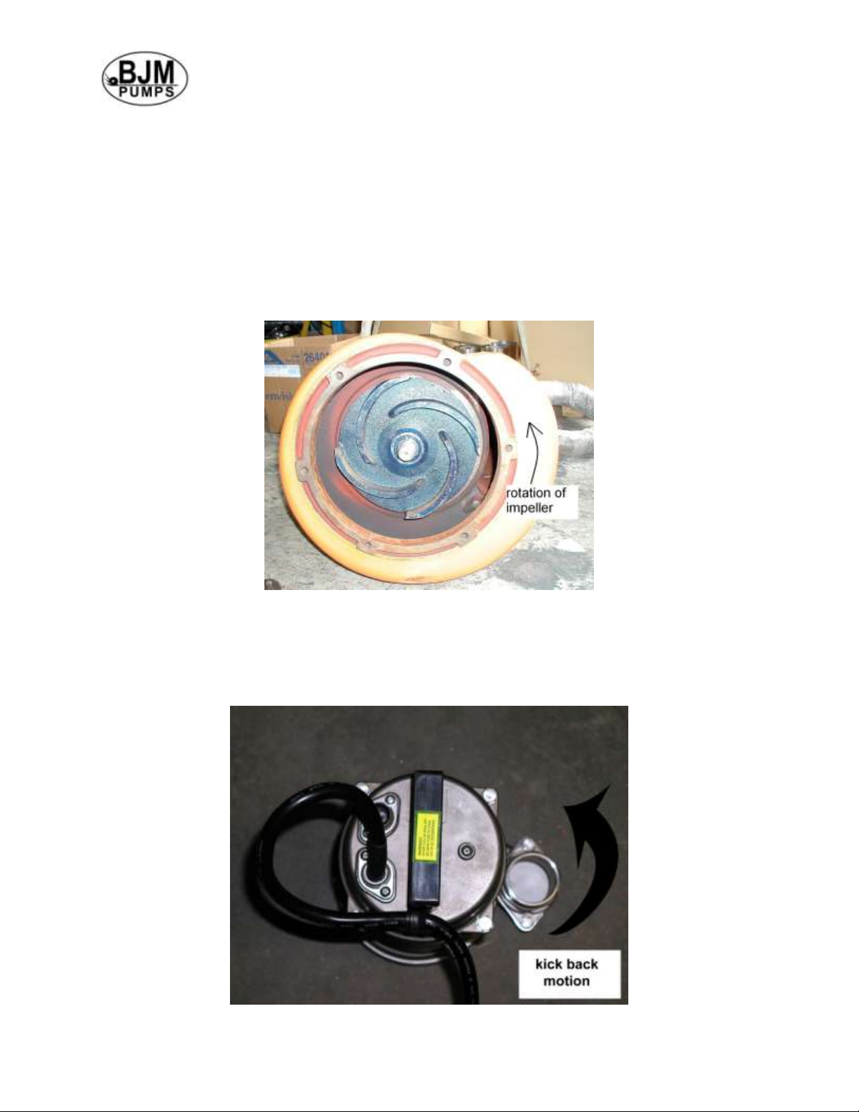
If wired properly to the control, the single phase BJM Pumps S-F and SX-F Series pump
should operate with the correct pumping rotation. Verification is recommended prior to
installing into the sump basin.
Two ways to check the correct pump rotation:
1. By looking at the impeller; the rotation of the impeller should be counter
clockwise as shown in the picture below.
2. By looking from the top of the pump. Since the impeller cannot be seen, the best
way to check the rotation is to check the kick back motion of the pump when the
pump just starts. The kick back motion of the pump should be counter clockwise
as shown in the picture below.
Page 9
9
PUMP OPERATION
This pump is designed to handle dirty water that contains some
solids. It is not designed to pump volatile or flammable liquids. Do not attempt to pump
any liquids which may damage the pump or endanger personnel as a result of pump
failure.
Do not operate this pump where explosive vapors or
flammable material exist. Death or Serious injury may result.
TYPICAL MANUAL WASTEWATER INSTALLATION
NOTE: Maximum recommended starts should not exceed 10 times per hour.
All S-F & SX-F models are provided with a 50’ (15 m) power cable. NEVER splice the
power cable due to safety and warranty considerations. Always keep the lead end dry.
Note: 208V, 230V, 460V & 575V three phase units do not have a plug and have to be
provided separately.
Do not alter the length or repair any power cable with a splice. The
pump motor and cable must be completely waterproof. Damage to the pump or
personal injury may result from alterations.
The BJM Pumps, S-F and SX-F series pumps require a special control that contains the
starting components, thermal sensor and Seal Minder connections. These pumps
cannot be directly connected to a power source.
Page 10
10
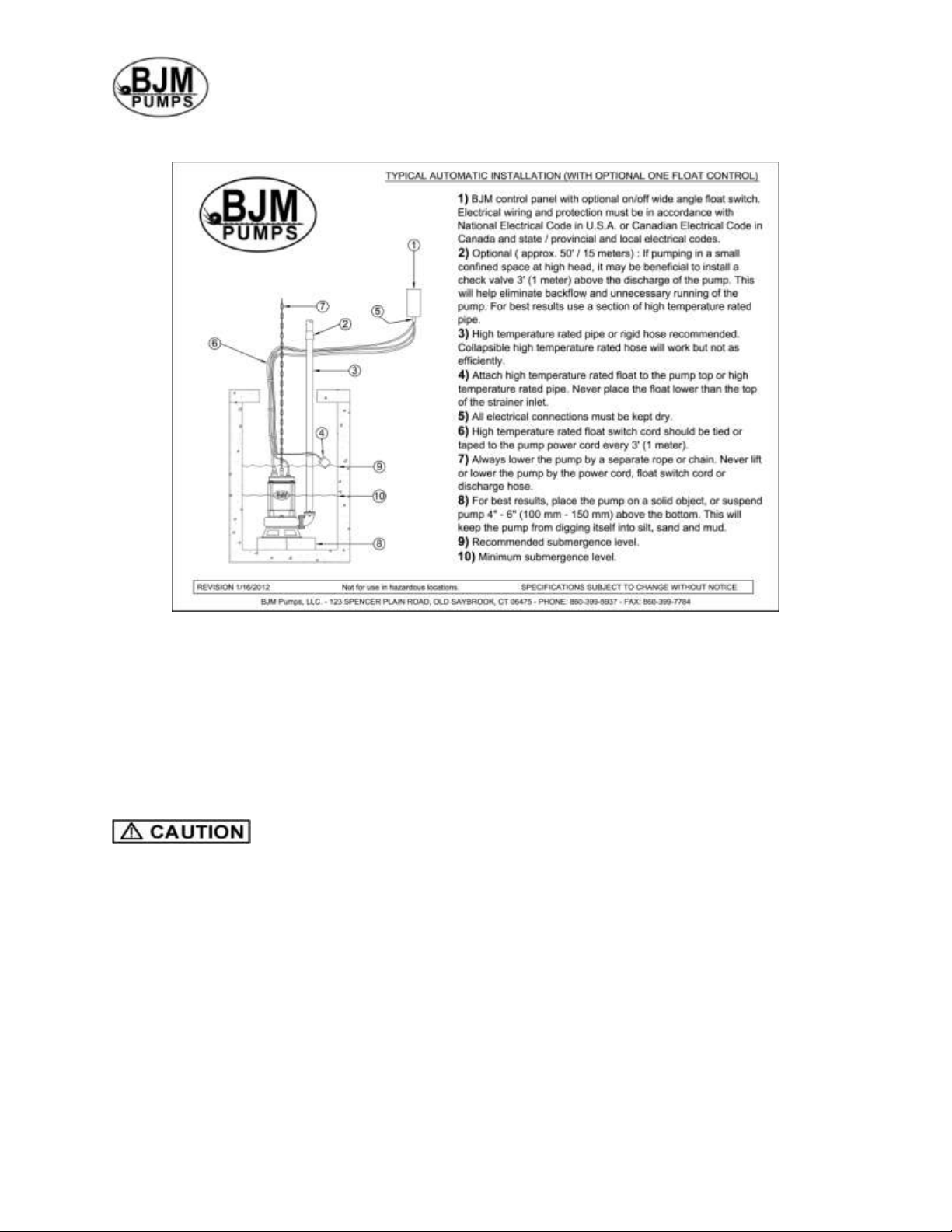
TYPICAL AUTOMATIC WASTEWATER INSTALLATION
NOTE: Maximum recommended starts should not exceed 10 times per hour.
STOPPING
To stop the pump (manual and automatic mode), unplug it from the power source, turn
off the breaker, or turn the power source off (generator).
CONTROL PANELS CONNECTION OPTIONS
Use with approved motor control that matches motor input in full
load amperes. “UTILLISER UN DÉMARREAR APPROUVÉ CONVENANT AU
COURANT Á PLEINE CHARGE DU MOTEUR.”
BJM Pumps has been evaluated for use with water or water based solutions. Please
contact the manufacturer for additional information.
Page 11
11
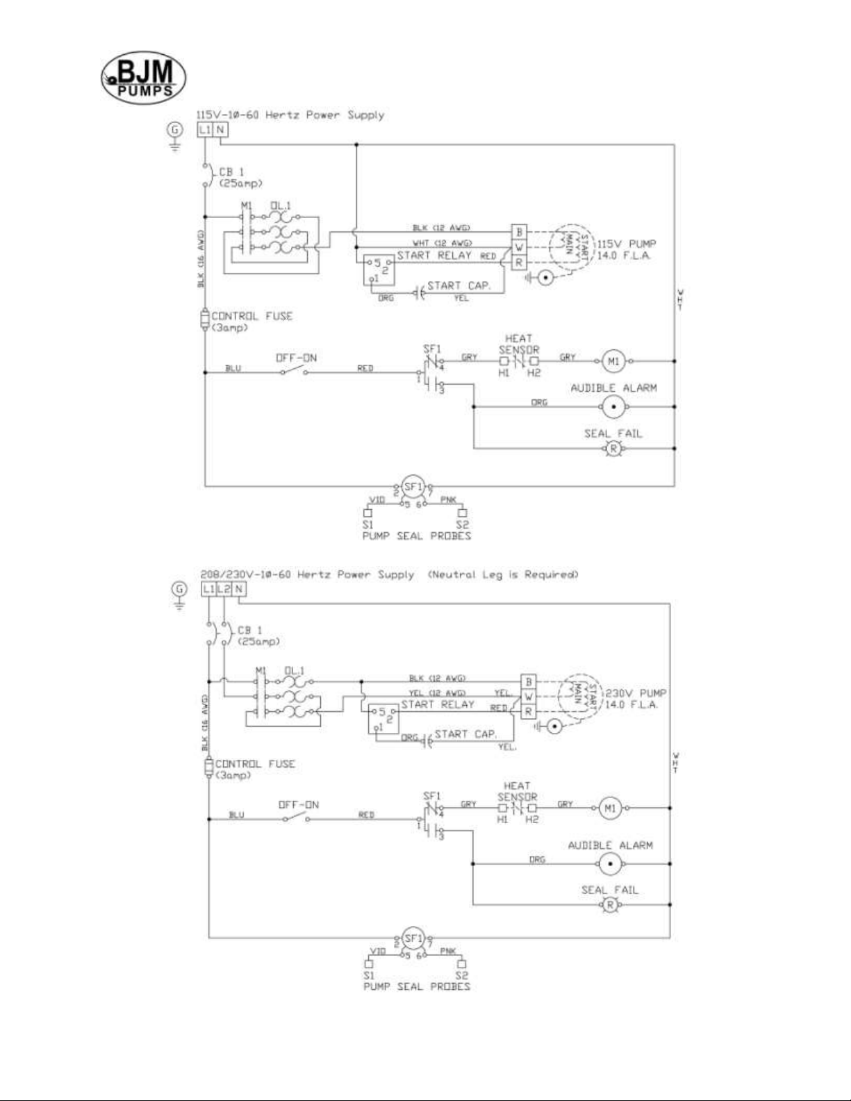
Figure 1 SX750F-115 control
Figure 2 SX750F-230, S1500F-230 and SX1500F-230 control
Page 12
12
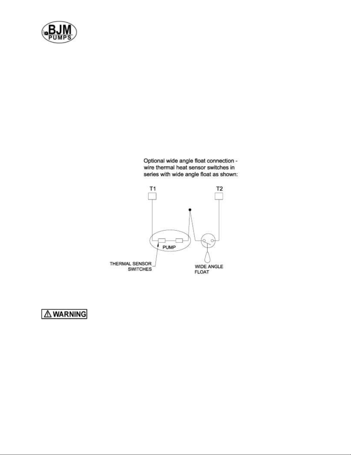
OPTIONAL FLOAT CONNECTION
BJM Pumps utilizes a control for all of the single phase “F” series pumps. The wiring
diagram included in this manual (and with the control) should be followed to properly
connect the pump power and sensor leads to the control, and the power supply to the
control. Care should be taken to make sure all of the connections are proper and that
the system is properly grounded. The control can be utilized as a portable control or as
a permanently mounted control enclosure. All Connections should be done to meet the
National Electric Code and all applicable local codes and ordinances.
The BJM Pumps control is supplied as a manual ON/OFF control. A wide angle float
can be wired in series with the thermal sensors to allow the pumps to operate in an
automatic mode. See the wiring diagram provided in this manual for proper connection.
A separate alarm control with float is available as an option from BJM Pumps.
TROUBLE SHOOTING
Disconnect the power source to the pump BEFORE attempting
any type of trouble shooting, service or repair.
PUMP WILL NOT RUN
1. Check power supply (fuses, breaker). Reset power.
2. Blocked impeller. Remove strainer, check and clean.
3. Defective cable or incorrect wiring.
4. Strainer clogged. Check and clean as necessary.
5. Float switch tangled/obstructed. Clean and free float switch from obstruction.
6. Float switch defective. Replace float switch.
7. Capacitor or start relay in control failed.
8. Thermal sensor switch is open/or failed.
Page 13
13
PUMP RUNS BUT DOES NOT DELIVER RATED CAPACITY
1. Discharge line clogged, restricted or hose kinked. Check discharge hose/pipe.
2. Worn impeller and/or suction cover. Inspect and replace as necessary.
3. Pump overloaded due to liquid pumped being too thick.
4. Pumping air. Check liquid level and position of pump.
5. Excessive voltage drops due to long cables.
6. Pump running backwards, check rotation.
SERVICING YOUR SUBMERSIBLE PUMP
Pump should be disconnected from the electric power supply before proceeding to do
any service or maintenance.
The design of the “F” series high temperature pump models is unique and
requires specific knowledge to perform the proper assembly. BJM Pumps
recommends that all electrical service work be performed at the factory, or by a
factory trained and certified repair technician, to insure that the materials and
assembly methods meet BJM standards.
MAINTAINING YOUR PUMP
Pump should be disconnected from the electric power supply before proceeding
to do any service or maintenance.
Pump should be inspected at regular intervals (At least 2 times per year).
More frequent inspections are required if the pump is used in a harsh
environment.
Preventative maintenance should be performed to reduce the chance of
premature failure.
Worn impellers and lip seals should be replaced.
Cut or cracked power cables must be replaced. (Never operate a pump with a
cut, cracked or damaged power cable.)
Seal oil should be checked once per year.
Maintenance should always be done when taking a pump out of service before
storage.
1) Clean pump of dirt and other build up.
2) Check condition of oil around the shaft seals.
3) Check hydraulic parts: check for wear.
4) Inspect power cable. Make sure that it is free of nicks or cuts.
CHANGING SEAL OIL
Changing the seal oil in the S-F & SX-F Series pumps is very easy.
1) Make sure that the pump is de-energized and locked out for service.
2) Lay the pump down on its side.
Page 14
14
3) Remove the screws that hold the bottom plate in place.
4) Remove bottom plate.
5) Remove screws holding the suction cover.
6) Remove the suction cover.
7) Remove the impeller.
8) Remove the inspection screw for the oil chamber (pos#50-08). Pour
out a small sample of the oil. If it is milky white, or contains water, then
the oil and possible, the mechanical seal, should be changed. If an oil
change is needed:
9) Remove the screws that hold the oil chamber cover in place & remove
the oil.
10) Replace the mechanical seal if necessary.
11) Replace the oil.
12) Assemble the pump.
STATOR REPLACEMENT OR ELECTRICAL REPAIR
The BJM Pumps “F” Series designed pumps utilize unique construction methods and
materials. The inner connection of all wiring requires use of a BJM wire connection kit.
Included in this kit are specific instructions on how a qualified factory trained and
certified repair technician can perform this work properly. No other materials or methods
should be used on this product.
Page 15
15
EXPLODED VIEW OF S1500C-F
Page 16
16
EXPLODED VIEW OF SX750CSS-F AND SX1500CSS-F
Page 17

17
Pump Model
S1500CF
Pos. No. Part Description
Item #
01-2 Stand 201986
05 Impeller 202098
07 Pump Housing 203008
08 Oil Chamber Cover 202213
08-1 O-Ring (Kit Only) Kit
09 Lip Seal FKM 202232
13 Mechanical Seal FKM** 200500
14 Lower Ball Bearing 200958
14-2 Lower Bearing Retainer Clip 202279
17 Rotor w/ Shaft 230V, 1PH 204111
18 Stator w/ Casing 230V, 1PH (High-Temp) 201040
19 Wire Connection Kit* 204211
20 Upper Ball Bearing 200967
21A Oil Chamber/Motor Housing 202196
21A-1 O-Ring (Kit Only) Kit
21B Motor Cover Upper 202368
26 Pump Top Cover (W/ Sensor opening) 202433
26-1 O-Ring (Kit Only) Kit
27 Power Cable w/ Gland-230V,1PH (High-Temp) 202783
27-1 O-Ring (Kit Only) Kit
27-2 Sensor Cable (High-Temp) 201743
27-2-1 O-Ring Kit Only Kit
31D Oil Sensor w/Wire and Ring Term. 202408
31E Ground Wire w/Ring Term. 203145
32 Power Cord Line Clip / Strain Relief 203161
33 Sensor Cord Line Clip 203163
34 Handle / Chain Handle 202517
35 Rod Bolts 202668
38 Discharge Nipple 3" 202534
38E Discharge Elbow 202558
38E-1 Gasket, Discharge Elbow FKM 203209
38F Discharge Flange 3" 202545
38F-1 Gasket, Discharge Flange FKM 202660
50-01-2 Bolt for Strainer/Stand 203228
50-07 Screw for Oil Chamber/Motor Housing 203228
50-08 Screw for Oil Chamber Cover 203219
50-11 Screw for Oil Fill 203218
50-11-1 O-Ring (Kit Only) Kit
50-12 Bolt - Suction Cover 203218
50-12-1 O-Ring (Kit Only) Kit
50-14-2 Screw 203219
50-27 Screw for Power Cord 203216
50-27-2 Screw for Sensor Cord 203216
50-31E Screw for Ground Wire 202692
50-32/50-33 Screw for Line Clip 203214
50-34 Screw for Handle 203219
50-38E Bolt for Discharge Elbow 203255
50-38F Bolt for Discharge Flange 203289
203197
O-Ring Kit - FKM
* "F" Series High Temperature Pumps Only
S-F SERIES PARTS LIST
Page 18

18
Pump Model SX750CSSF SX1500CSSF
Pos. No. Part Description
Item # Item #
01-2 Stand 201985 201987
05 Impeller 202095 202097
07 Pump Housing 202176 202172
07-1 O-Ring (Kit Only) Kit Kit
08 Oil Chamber Cover 202214 202214
08-1 O-Ring (Kit Only) Kit Kit
09 Lip Seal FKM 202232 202232
13 Mechanical Seal FKM** 200500 200500
14 Lower Ball Bearing 200958 200958
14-2 Lower Bearing Retainer 202279 202279
17 Rotor w/ Shaft 115/230V, 1PH 204061 204110
18 Stator w/ Casing 115V, 1PH (High-Temp) 201038 -
18 Stator w/ Casing 230V, 1PH (High-Temp) 201039 201041
19 Wire Connection Kit* 204211 204211
20 Upper Ball Bearing 200967 200967
21A Oil Chamber/Motor Housing 202197 202197
21A-1 O-Ring (Kit Only) Kit Kit
21B Motor Cover Upper 202368 202368
26 Pump Top Cover (W/ Sensor opening) 202434 202434
26-1 O-Ring (Kit Only) Kit Kit
27 Power Cable w/ Gland- 115V,1PH (High-Temp) 202783 -
27 Power Cable w/ Gland-230V, 1PH (High-Temp) 202784 202783
27-1 O-Ring (Kit Only) Kit Kit
27-2 Sensor Cable (High-Temp) 201743 201743
27-2-1 O-Ring Kit Only Kit Kit
31D Oil Sensor w/Wire and Ring Term. 202408 202408
31E Ground Wire w/Ring Term. 203145 203145
32 Power Cord Line Clip / Strain Relief 203166 203166
33 Sensor Cord Line Clip 203163 203163
34 Handle / Chain Handle 202517 202517
35 Rod Bolts 202682 202683
38 Discharge Nippple 2" 202532 -
38 Discharge Nipple 3" - 202535
38E Discharge Elbow 202571 202559
38E-1
O-Ring, Discharge Elbow FKM
203326 203327
38F Discharge Flange 2" 202563 -
38F Discharge Flange 3" - 202546
38F-1 O-Ring, 2" Discharge Flange FKM 202723 -
38F-1 Bolt - Suction Cover - 202724
50-01-2 Bolt for Strainer/Stand 203228 203228
50-07 Screw for Oil Chamber/Motor Housing 203296 203296
50-08 Screw for Oil Chamber Cover 203219 203219
50-11 Screw for Oil Fill 203218 203218
50-11-1 O-Ring (Kit Only) Kit Kit
50-12 Screw for Pressure Check 203218 203218
50-12-1 O-Ring (Kit Only) Kit Kit
50-14-2 Screw for Bearing Retainer 203219 203219
50-27 Screw for Power Cord 203295 203295
50-27-2 Screw for Sensor Cord 203295 203295
50-31E Screw for Ground Wire 202692 202692
50-32/50-33 Screw for Line Clip 203214 203214
50-34 Screw for Handle 203219 203219
50-38E Bolt for Discharge Elbow 203294 203271
50-38F Bolt for Discharge Flange 203229 203294
202630 202630
O-Ring Kit - FKM
* "F" Series High Temperature Pumps Only
SX-F SERIES PARTS LIST
Page 19
19
SINGLE PHASE WIRING DIAGRAM
115V & 230V
MODELS S1500CF, SX750CSSF & SX1500CSSF
Page 20
20
SEAL MINDER® - THERMAL MOTOR SENSOR SWITCH
(For high temperature single phase pump models)
Seal Minder:
Also known as a seal failure circuit (or moisture detection circuit) is designed to inform the pump
operator that there is moisture within the oil chamber. This early warning can allow the operator to
schedule repair & inspection on the pump. The Seal Minder sensor probe is inside the oil chamber.
(The oil chamber houses the mechanical seals that are cooled & lubricated by oil). The Seal Minder,
when properly connected to a control panel, can help indicate seal failure. The Seal Minder cable
requires a seal fail circuit in control panel for warning signal.
Along, with the Seal Minder, the Fahrenheit™ Series high temperature pumps also feature
thermal temperature sensor switches that are imbedded into the motor stator windings. Two switches
are imbedded into the stator windings and wired in series. The leads are connected to the pump
control panel through the sensor cable. If the windings would see a temperature above 300 degrees
F, then the switch(s) would open and cut power to the pump. Once the temperature dropped below
300 degrees F, the switch(s) would reset, and the pump would be returned to a state of operation.
This feature is designed to prevent damage to the stator winding and allow for longer pump life.
The sensor cable consists of four leads, two are connected to the Seal Minder, and two are
connected to the thermal sensor switches located in the stator windings (Note on 400 models the
sensor and power are in a single cable).These four leads run to the pump control panel and connect
to the proper connections points for seal alarm and thermal cut off. The black and white wires on 7501500 models, black with white stripes and white with black stripes on 400 models; are for the Seal
Minder connections and the thermal sensors will be connected to the yellow and red wires on 7501500 models, yellow and red with yellow stripes on 400 models (see details on wiring diagram). The
single phase wiring diagram shown earlier in the manual will give a guide to the connections in the
control panel. The manual for the control panel should be consulted for the exact connections.
The sensor cable with Seal Minder and thermal sensor switch connections is standard on all
Fahrenheit™ Series high temperature pumps (Note the 400 models have a different wire color
code in the single cable design). The cable is designed for a high temperature environment. The
proper replacement part can be found parts list found in this manual. BJM Pumps, can supply a
control with the Seal Minder and Thermal sensor switch option. BJM Pumps requires the Seal Minder
and thermal sensor switches be used. Failure to connect or misuse of these devices will void
warranty.
Page 21

21
BJM PUMPS, LLC
123 Spencer Plain Road
Old Saybrook, CT 06475, U.S.A.
WARRANTY AND LIMITATION OF LIABILITY
Unless otherwise expressly authorized in writing, specifying a longer or shorter period, BJM
Pumps, LLC warrants for a period of eighteen (18) months from the date of shipment from the
Point of Shipment, or one (1) year from the date of installation, whichever occurs first, that all
products or parts thereof furnished by BJM Pumps, LLC under the brand name BJM Pumps,
hereinafter referred to as the “Product” are free from defects in materials and workmanship and
conform to the applicable specification.
BJM Pumps, LLC’s liability for any breach of this warranty shall be limited solely to replacement
or repair, at the sole option of BJM Pumps, LLC, of any part or parts of the Product found to be
defective during the warranty period, provided the Product is properly installed and is being
used as originally intended. Any breach of this warranty must be reported to BJM Pumps, LLC
or BJM Pumps, LLC’s authorized service representative within the aforementioned warranty
period, and defective Product or parts thereof must be shipped to BJM Pumps, LLC or BJM
Pumps, LLC’s authorized representative, transportation charges prepaid. Any cost associated
with removal or installation of a defective Product or part is excluded.
IT IS EXPRESSLY AGREED THAT THIS SHALL BE THE SOLE AND EXCLUSIVE REMEDY
OF BJM PUMPS, LLC’S DISTRIBUTORS AND CUSTOMERS. UNDER NO CIRCUMSTANCES
SHALL BJM PUMPS, LLC BE LIABLE FOR ANY COSTS, LOSS, EXPENSE, DAMAGES,
SPECIAL DAMAGES, INCIDENTAL DAMAGES OR CONSEQUENTIAL DAMAGES ARISING
DIRECTLY OR INDIRECTLY FROM THE DESIGN, MANUFACTURE, SALE, USE OR REPAIR
OF THE PRODUCT, WHETHER BASED ON WARRANTY, CONTRACT, NEGLIGENCE, OR
STRICT LIABILITY. IN NO EVENT WILL LIABILITY EXCEED THE PURCHASE PRICE OF
THE PRODUCT.
THE WARRANTY AND LIMITS OF LIABILITY CONTAINED HEREIN ARE IN LIEU OF ALL
OTHER WARRANTIES AND LIABILITIES, EXPRESSED OR IMPLIED. ALL IMPLIED
WARRANTIES OF MERCHANTABILITY AND FITNESS FOR A PARTICULAR PURPOSE ARE
HEREBY DISCLAIMED BY BJM PUMPS, LLC AND EXCLUDED FROM THIS WARRANTY.
BJM Pumps, LLC neither assumes, nor authorizes any person to assume for it, any other
warranty obligation in connection with the sale of the Product. This warranty shall not apply to
any Product or parts of Product which have (a) been repaired or altered outside of BJM Pumps,
LLC’s facilities unless such repair was authorized in advance by BJM Pumps, LLC or by its
authorized representative; or (b) have been subject to misuse, negligence or accident; or (c)
have been used in a manner contrary to BJM Pumps, LLC’s instruction.
In any case of products not manufactured and sold under the BJM Pumps, LLC brand name,
there is no warranty from BJM Pumps, LLC; however BJM Pumps, LLC will extend any warranty
received from BJM Pumps, LLC’s supplier of such products.
Page 22
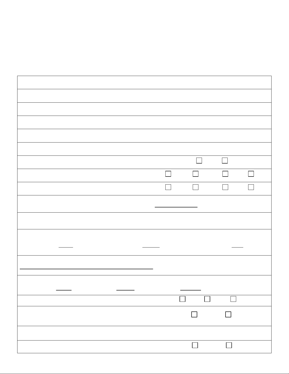
START-UP REPORT FORM
Pump Owner’s Name
Location of Installation
Date of Installation:
Dealer
Dealer Phone ( )
Date of Purchase
Model
Serial No
Voltage
Phase
Hertz
HP
Does impeller turn freely by hand?
Yes No
Condition of Equipment
New Good Fair Poor
Condition of Cable Jacket
New Good Fair Poor
Rotation: Direction of Impeller Rotation (viewed from bottom)
(Use C/W for clockwise, CC/W for counterclockwise):
Resistance of cable and Pump Motor (measured at pump control)
Red-Black ohms
Red-White ohms
White-Black ohms
Resistance of ground circuit between control panel and outside of pumps
Ohms
MEG OHM CHECK OF INSULATION
Red to ground White to ground Black to ground
Condition of location at start-up
Dry Wet Muddy
Was equipment stored
If YES, length of storage:
Yes No.
Liquid being pump
Debris in bottom of station?
Yes No
START-UP REPORT FORM
This form is designed to record the initial installation, and to serve as a guide for troubleshooting at a
later date (if needed).
BJM Pumps, LLC
123 Spencer Plain Road
Old Saybrook, CT. 06475
Page 23
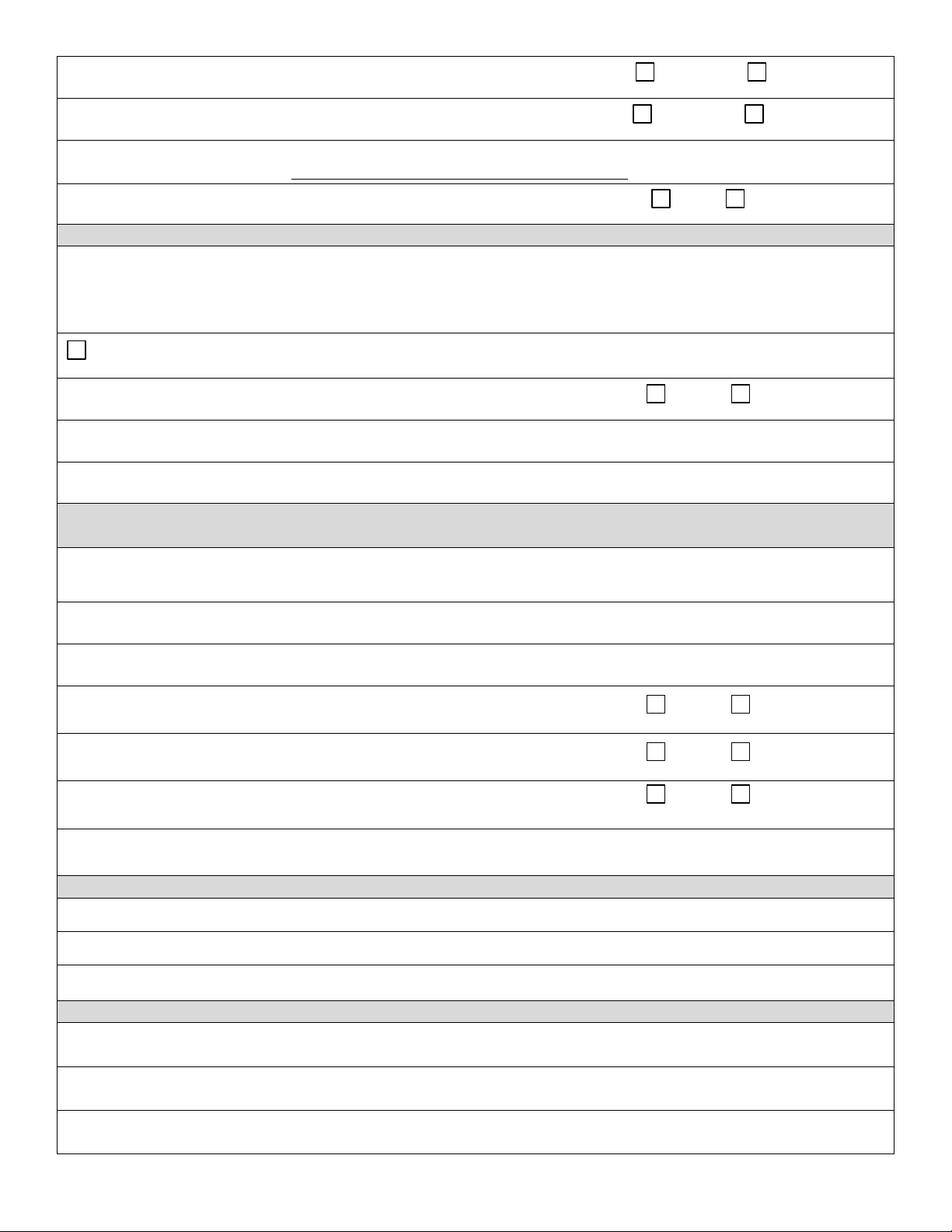
START-UP REPORT FORM
Are guide rails vertical?
Yes No
Is base elbow installed level?
Yes No
Liquid level controls: Model
Is control installed away from turbulence?
Yes No
Float Operation Check
Tip lowest float (stop float), all pumps should remain off.
Tip second float (and stop float), one pump comes on.
Tip third float (and stop float), both pumps on (alarm on simplex).
Tip fourth float (and stop float), high level alarm on (omit on simplex).
Check here if using manual on/off only.
Does liquid level ever drop below volute top?
Yes No
Control Panel MFG & model no.
Number of pumps operated by control panel
NOTE: At no time should hole be made in top of control panel, unless proper sealing
devices are utilized.
Short Circuit protection:
Type:
Number and size of short circuit device(s)
Amp rating:
Overload type:
Size:
Amp rating:
Do protective devices comply with pump motor amp
rating?
Yes No
Are all pump connections tight?
Yes No
Is the interior of the panel dry?
Yes No
If No, correct moisture problem.
SINGLE PHASE
Voltage supply at panel line connection, pump off
L1
L2
Voltage supply at panel line connection, pump on
L1
L2
Amperage load connection, pump on
L1
L2
THREE PHASE
Voltage supply at panel line connection, pump off
L1-L2
L2-L3
L3-L1
Voltage supply at panel line connection, pump on
Page 24
START-UP REPORT FORM
L1-L2
L2-L3
L3-L1
Amperage load connection, pump on
L1
L2
L3
FINAL CHECK
Is pump secured properly?
Yes No
Was pump checked for leaks?
Yes No
Do check valves operate properly?
Yes No
Flow: Do pumps appear to operate at proper rate?
Yes No
Noise level:
Acceptable
Unacceptable
Comments:
Installed by:
Company:
Person:
Date:
Page 25

NOTES:
Page 26

BJM Pumps, LLC
123 Spencer Plain Road • PO Box 1138 • Old Saybrook, CT 06475, USA
• Phone: (860) 399-5937 • Fax: (860) 399-7784
Email: sales@bjmpumps.com • Web Site: www.bjmpumps.com
FARHENHEIT
BJM Pumps & Seal Minder is a registered trademark of BJM Pumps, LLC
Copyright © 2009-2013 BJM Pumps, LLC. All rights reserved
™
is a trademark of BJM Pumps, LLC.
 Loading...