


MaxFire
Installation, Operating and Maintenance
Instructions
MaxFireTM Multi-Fuel Room Heater
WARNING! Please read this entire manual before installation and use of the Bixby MaxFireTM Multi-Fuel
Room Heater. Failure to follow these instructions could result in property damage, bodily injury or even death.
Contact local building officials, fire officials or the authority having jurisdiction about restrictions, permits and
installation inspection requirements in your area.
Save these instructions for future reference.
PLEASE RECORD THE FOLLOWING INFORMATION:
MODEL _______________ DEALERSHIP _______________ INSTALLER _______________
DATE PURCHASED _______________ DEALER PHONE _______________ INSTALLER PHONE _______________
SERIAL NUMBER ____________________________
Bixby Energy Systems
877-500-2800
www.bixbyenergy.com


TABLE OF CONTENTS
Safety Information 2
Specifications 4
Planning the Installation 6
Venting Installation and Instructions 9
Log Placement Instructions 20
Operating Instructions 21
Maintenance and Cleaning Procedures 24
Minimum Clearances to Combustible Materials
Performing the Installation
Optional Thermostat Operation
Leveling the Room Heater
Vent System Approvals
Venting Components
Inspections
Permits
Vent Maintenance
Vent Location
Location of Exhaust
General Vent Installation Instructions
Fuel
Start Up
Flashing Indicator Light System
Fire Pot/Burner
Ash Drawer
Heat Exchanger Tubes
Soot and Fly-ash Formation and Need for Removal
Cleaning the Exhaust Manifold
Exhaust Fan
Fuel Hopper
Cleaning the Glass
Cleaning the Feeder Tube
Cleaning the Lower Paddle
Cleaning the Air Filter for the Ignition Air Compressor
Replacing the Room Heater Filter
Troubleshooting Procedures 29
Wiring Diagram 31
Service Parts List 32
Optional Accessories 34
Venting Parts List 35
Maintenance Log 38
2020866 REV A
1
SAFETY INFORMATION
1. Install and use only in accordance with these installation and operating instructions, page 9. Contact
local building officials, fire officials, or the authority having jurisdiction about restrictions, permits,
and inspection requirements in your area.
2. Refer to instructions and local codes for precautions required for passing the vent pipe through a
combustible wall or ceiling. Inspect and clean vent system frequently in accordance with manufacture’s
instructions.
3. DO NOT INSTALL A FLUE DAMPER IN THE EXHAUST VENTING SYSTEM OF THIS UNIT.
4. DO NOT CONNECT THIS UNIT TO A CHIMNEY SERVING ANOTHER APPLIANCE.
5. INSTALL VENT AT CLEARANCES SPECIFIED IN THE VENTING SECTION.
6. For use with only whole corn kernels, wood pellet fuel or approved pelletized biomass.
7. DO NOT BURN GARBAGE, OR FLAMMABLE FLUIDS SUCH AS GASOLINE, NAPTHA OR
ENGINE OIL IN YOUR BIXBY ROOM HEATER. Store any fuel away from your heater.
- Pellet stove starter gel may be used to assist in the lighting of the Room Heater. See lighting
instructions.
8. Always unplug the heater before cleaning or servicing.
9. Dispose of all ashes in a metal container.
10. The use of a protective screen (i.e. fireplace screen) is recommended when children or animals are
present.
11. DO NOT INSTALL IN A SLEEPING ROOM.
12. The door must be closed and latched during operation. Always allow the Room Heater to cool before
opening the door to clean the firebox and / or the glass. If door must be opened during operation, use
caution as embers may escape from combustion chamber.
WARNING: Biomass (i.e. corn, wood) is a solid material and by its very nature will accumulate ash that
must be cleaned out of the Room Heater and venting on a regular basis. See cleaning and
maintenance schedule. FAILURE TO DO SO MAY VOID WARRANTY.
NOTE: It is recommended that a carbon monoxide detector be installed to ensure protection from the
hazards of carbon monoxide. It is also recommended that a smoke detector be installed for
early warning in case of fire.
CAUTION: FRONT SURFACES OF THE BIXBY ROOM HEATER WILL BE HOT WHEN THE
UNIT IS IN OPERATION. DO NOT TOUCH, AND KEEP CHILDREN AND CLOTHING
AWAY. CONTACT MAY CAUSE SEVERE BURNS. KEEP FURNISHINGS AND OTHER
COMBUSTIBLE MATERIALS AT LEAST 2 FT. (610 MM) DISTANCE AWAY FROM THE
BIXBY ROOM HEATER.
2
2020866 REV A
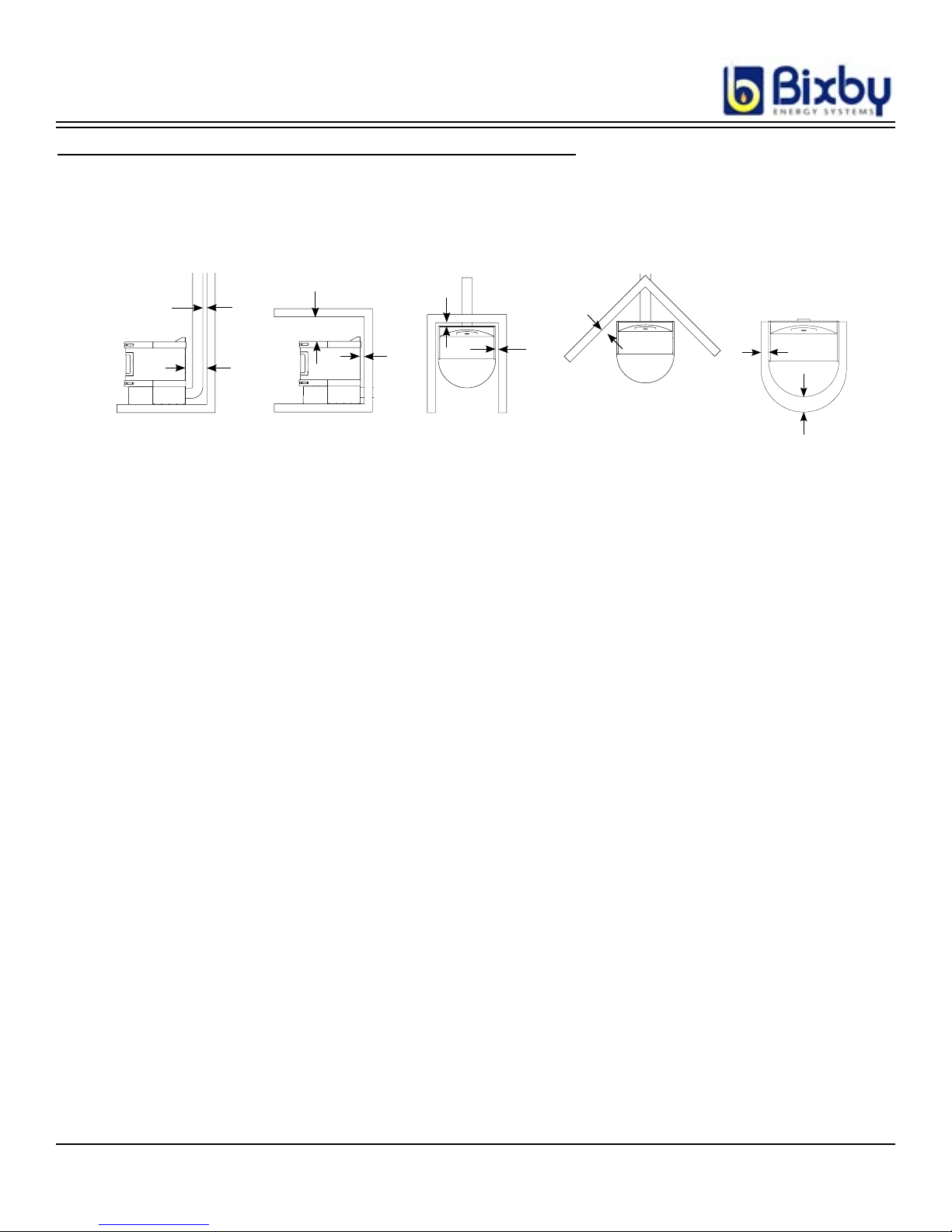
MINIMUM CLEARANCES TO COMBUSTIBLE MATERIALS
C
B
A
B
B
B
B
Floor Protector
E
D
Free Standing and Alcove (rear only) Installation Clearances:
A 10.5” (267mm) D 6” (150mm)
B 2” (50mm) E 3” (75mm)
C 12” (305mm)
NOTE: Minimum clearances are for temperature concerns and do not allow for enough room
for maintenance. Please allow enough room on the sides for routine maintenance,
6” - 12” (150mm - 305mm) of clearance to non-movable objects (i.e. walls)
is recommended. Also, clearance to the back of the Room Heater is needed for
replacement of the filter.
Use a non-combustible floor protector under the unit, extending 3” (76mm) past the side of unit
(or less if installed at closer clearances) and 6” (150mm) in front of Room Heater door.
Minimum Height - 42” (1065mm), Minimum Width - 32” (815mm),
2020866 REV A
Alcove Dimensions (Rear Vent Only):
Maximum Depth - 24” (610mm)
3
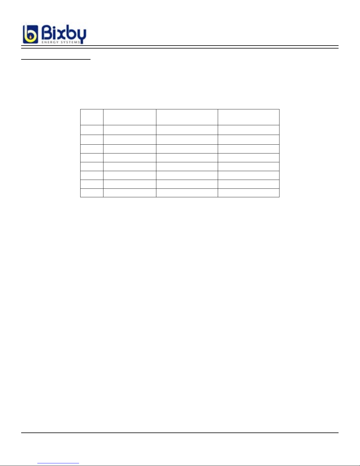
SPECIFICATIONS
Fuel: Multi-fuel System: Dry shelled corn, Wood Pellets (recommended maximum size approximately ¼ in. diameter x 1¼ in.
long), or “BIXBY” certified Blue or Green Biomass pellets. The use of “cracked corn” is not recommended due to feed and
burn issues. The use of lower quality corn with foreign material (cobs, stones, or other material) may cause feed issues. In
addition, the use of seed corn is not recommended due to the coating interfering with the operation of the Room Heater. When
loading the corn into the hopper, remove as much foreign material as possible. See Operating Instructions (page 21) for more
information.
Level Approx. Feed Rate
lbs/hr (kg/hr)
1 1.8 (0.8) 21 hrs 57
2 2.1 (1.0) 17 1/2 hrs 48
3 2.3 (1.1) 16 hrs 43
4 2.6 (1.2) 14 hrs 38
5 3.0 (1.4) 12 1/2 hrs 34
6 3.5 (1.6) 10 1/2 hrs 29
7 3.9 (1.8) 9 1/2 hrs 26
8 4.6 (2.1) 8 hrs 22
*Assumes running at a single level, actual time will vary as the burn level changes,
starting and shutting down, and trim knob adjustments.
Heating Area: Varies depending on floor plan, heat loss, geographic location, altitude, heater venting configuration, moisture
content of fuel and climate.
Time Between
Ash Dumps *
Approximate Hours/
Full Load *
Installation: Install in accordance with “BIXBY” instructions and local building codes.
Shipping Weight: 380 pounds (172 kg)
Electrical: 120 VAC, 60 Hz., 15 amp Service Required, dedicated line recommended
Start: 10 Amps
Run: 2 Amps
Dimensions: Height = 33 in (838 mm)
Width = 28 in (711 mm)
Depth = 30 in (762 mm)
Fuel Hopper Capacity: 2.4 cu. ft. (approx. 106 lbs. shelled corn)
Listing: The Bixby MaxFireTM Multi-Fuel Room Heater was tested by OMNI-Test Laboratories, Beaverton, Oregon
to ASTM E1509 and ULC C1482 (report number 223-S-06-2). Emission tests were also conducted per the
USA Environmental Protection test methods 28A and 5G for particulate emissions. The Max-Fire
TM
is exempt
under 40 CFR 60.531, therefore the results have not been submitted to the EPA.
The results are as follows:
Category 1 (low burn) 2.3 grams per hour (.081 ounces)
Category 2 (medium low burn) 2.0 grams per hour (.070 ounces)
Category 3 (medium high burn) 2.42 grams per hour (.085 ounces)
Category 4 (high burn) 2.21 grams per hour (.077 ounces)
Overall weighted average 2.25 grams per hour (.079 ounces)
4
2020866 REV A

IMPORTANT:
Proper material handling equipment must be available to safely transport and position the Bixby Room Heater.
1. Remove the protective packaging, using appropriate tools, and detach the unit from its
shipping pallet. The Room Heater is attached to the pallet with two bolts. Remove the side
pannels to gain access to the bolts.
2. Using a suitable transporting device, move the unit to the desired location, centering it on
the Bixby Hearth Pad or an alternate protective plate. Care should be taken not to mar the
Hearth Pad. Placing protective material under the Bixby Room Heater when positioning
is recommended.
3. Use the included bulls-eye level to level the unit by adjusting the height of its legs. Leveling the unit is required to maintain even fuel distribution. See Page 8 for more information.
MOBILE HOME INSTALLATION
WARNING: DO NOT INSTALL IN A SLEEPING ROOM.
CAUTION: THE STRUCTURAL INTEGRITY OF THE MOBILE HOME FLOOR, WALLS AND
CEILING / ROOF MUST BE MAINTAINED (i.e. Do not cut through floor joists, wall studs,
ceiling trusses, etc.)
1. A Bixby Direct-Vent system must be used to provide an outside air inlet for combustion air
and must be unrestricted.
2. The Room Heater must be secured to the mobile home by bolting it to the floor (using lag
bolts).
3. The Room Heater must be grounded with #8 copper grounding wire or equivalent, terminated at each end with an NEC approved grounding device.
4. Refer to pages 16 and 17 for typical horizontal or vertical mobile home venting installation.
5. Refer to clearances to combustibles section on pages 3 and 11 for distances to combustibles
and appropriate chimney systems.
6. Seal all wall and floor inlets to prevent air or moisture penetration. Check periodically to
ensure inlet is free of obstruction, such as snow and ice.
7. Installation should be in accordance with the Manufactured Home and Safety Standard
(HUD), CFR 3280, Part 24.
2020866 REV A
5
PLANNING THE INSTALLATION
The Bixby Max-FireTM Room Heater is intended for use in buildings, manufactured homes or for mobile home
installation (see previous page for mobile home installation instructions).
CAUTION: The Max-FireTM Room Heater should not be installed at a location where it could come in contact
with curtains, drapes, walls, carpeting or other combustible surfaces. The Room Heater must not
be installed in a sleeping room. When choosing a location, proximity to an electrical outlet (do not
use an extension cord) and the best location for the venting outlet and its connecting piping should
be considered. See Venting Installation and Instructions, page 9.
CAUTION: This Room Heater must be installed only by an authorized dealer, and/or by individuals who are
technically qualified and versed in any local codes or regulations that may apply to installation and
application of heating equipment of this type. Clearances specified in this manual are minimum
and any reduction must be approved by the regulatory authority.
To assure safe operation, it is absolutely essential that a floor protective device of metal or other non-combustible
material be in place beneath the Room Heater. Note drawing below to determine dimensions the size of the mat.
Lightweight, properly sized hearth pads are available from Bixby Energy Systems in colors to match your Room
Heater.
The non-combustible floor protector should extend under unit 3
in. (76mm) to each side of unit when installed in a free standing
location and 6 in. (152 mm) in front of Room Heater door. The
floor protector can be less than 3 in.(76mm) if installed in an
A
A
alcove. See Minimum Clearances, page 3.
A = 3 in. (76mm)
B = 6 in. (152mm)
B
Figure 1
PERFORMING THE INSTALLATION
The unit is shipped completely assembled. It is enclosed in protective packaging material and attached to a
shipping pallet. A shop cart or other suitable material handling device (minimum capacity of 400 lbs. (180kg))
will be needed to transport the Bixby Room Heater to its desired location. To bring the Room Heater into the room
chosen, a door opening of at least 2 ft. 8 in.(80cm) will be needed. Appropriate tools will be needed to connect
the venting pipes and fittings, as well as a hole-cutting device for venting the piping to the outside. The side of
the shipping box can be used to help locate the Room Heater and the vent hole location.
6
2020866 REV A
FEED
RATE
353
5
- 0 +
THERMOSTAT CONNECTION
2021781 REV A
EXHAUST
FAN
- 0 +
353
5
FUEL
CORN
WOOD
OPTIONAL THERMOSTAT OPERATION
The Room Heater is designed so that it can be operated by a wall mounted thermostat. This option is not provided
directly from the factory, but can be purchased from your dealer or the Bixby website (www.bixbyenergy.com) or
any other “on/off” 24V AC wall mounted thermostat can be used. Do not use a powered thermostat to avoid
damage to the Room Heater. Follow the the thermostat installation instructions carefully.
NOTE: Thermostat should be mounted on an inside wall and not in direct line with the Room Heater
convection air. A prefered location would be on an inside wall opposite the Room Heater.
When the thermostat is hooked up and calling for heat, the Room Heater will display the currently selected level
using the LEDs. If the thermostat is NOT calling for heat, the currently selected level will be displayed, but all
the LEDs will be slowly flashing in unison and the Room Heater run at level 1.
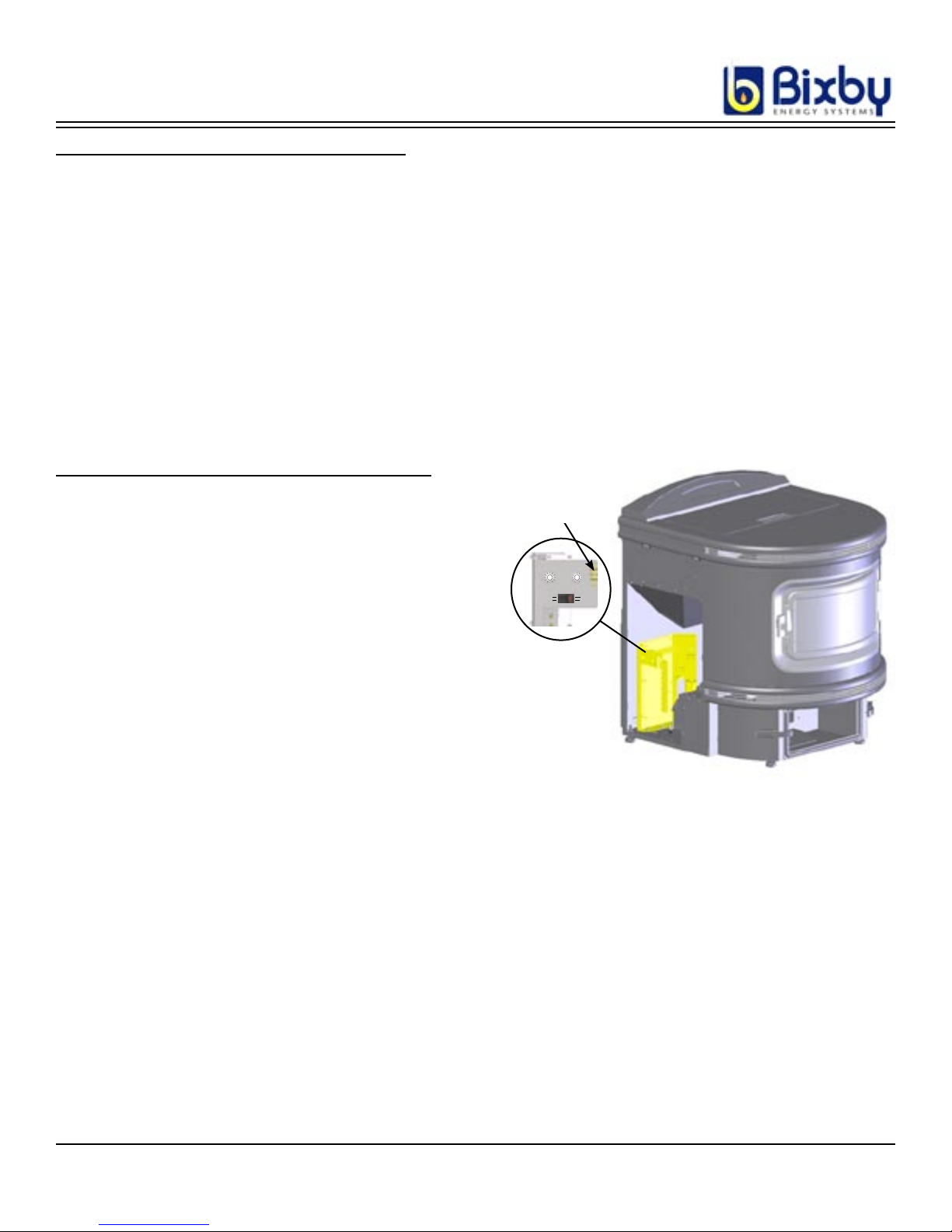
THERMOSTAT INSTALATION INSTRUCTIONS
1. Unplug the Room Heater.
Thermostat connection
2. Remove the left side panel.
3. Locate the Trim Pot / Thermostat bracket.
4. Loosen the middle two screws on the thermostat
block and remove the metal jumper.
5. Run the wire for the thermostat through the
black grommet on the back panel.
6. Attach the wires of the thermostat to the two
terminals.
7. Replace the side panel.
Figure 2
2020866 REV A
7
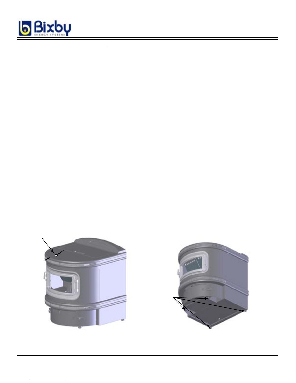
LEVELING THE ROOM HEATER
CAUTION: THE ROOM HEATER SHOULD BE LEVELED BEFORE ATTACHING THE VENT PIPE.
The supplied bulls eye level can be used to level the Room Heater front-to-back and side-to-side, a 6 in.
level may also be used.
1. Place the level centered side-to-side and about 4 in. (10cm) back from the front of the Room Heater on the
top surface. The bubble should end up centered inside the middle circle on the level. If the bubble is not
in that position, the bubble will be towards the high side of the Room Heater. See Figure 3.
2. Locate the leveling feet on the bottom of the Room Heater. See Figure 4.
3. Lift the Room Heater near the foot to be raised (low side, opposite the bubble on the level). A pry bar can
be used to lift the Room Heater with a wooden shim or something similar to protect the hearth pad.
4. With the corner of the Room Heater elevated, place a piece of wood (or other blocking) under the Room
Heater to hold it while adjusting the leg. The leg length should be adjusted by hand, but if needed a wrench
maybe used. This will not work if the foot is turned all the way in, as that portion will not be accessible.
5. Remove the block using the prybar and check adjustment.
6. Proceed to adjust the feet until the bubble is centered inside the inner circle. This is a very important step
as the feed system is gravity fed and it will ensure that the fuel is fed into the burn pot correctly.
8
Bulls Eye Level
4”
Leveling
Legs
Figure 3 Figure 4
2020866 REV A

VENTING INSTALLATION AND INSTRUCTIONS
WARNING:
A MAJOR CAUSE OF VENT RELATED FIRES IS FAILURE TO MAINTAIN REQUIRED
CLEARANCES (AIR SPACES) TO COMBUSTIBLE MATERIALS. IT IS OF THE
UTMOST IMPORTANCE THAT THIS VENT SYSTEM BE INSTALLED ONLY IN
ACCORDANCE WITH THESE INSTRUCTIONS.
VENT SYSTEM APPROVALS
BIXBY DIRECT VENT PIPE is listed by OMNI-Test Laboratories, Inc. as a vent for BIXBY pellet and corn Room
Heaters only. NO OTHER PIPE IS LISTED FOR USE WITH BIXBY ROOM HEATERS. The use of non-Bixby
vent pipe will void the Room Heater’s warranty. The minimum clearance from this vent to combustible materials
is 2 in. (50mm). Combustible materials include but are not limited to lumber, plywood, sheetrock, plaster and lath,
furniture, curtains, electrical wiring, and building insulation of any kind. Never fill any required clearance space
with insulation or any other materials.
This vent is tested and listed by OMNI-Test Laboratories, Inc. to UL Standard 641 and to ULC/ORD-C441
(Canada) for safe low temperature venting systems, Type L, and produced under the factory inspection and followup program of OMNI-Test Laboratories, Inc.
NEVER INSTALL SINGLE-WALL PIPE TO THE Room Heater.
NOTE:
Proper planning for your vent installation will result in greater safety, efficiency, and convenience, saving both
time and money. Use only authorized BIXBY ENERGY SYSTEMS, INC. listed parts. Do not install damaged
parts.
TOOLS AND EQUIPMENT
Level (a six inch level is recommended)
Eye protection
Hammer
Screwdriver
Tape measure
High temperature waterproof sealant (min 500F)
Saber or keyhole saw
Stud finder
Adjustable wrench
Gloves
CAUTION: The Room Heater should be leveled before attaching the vent pipe. See page 8 for leveling
information.
2020866 REV A
9
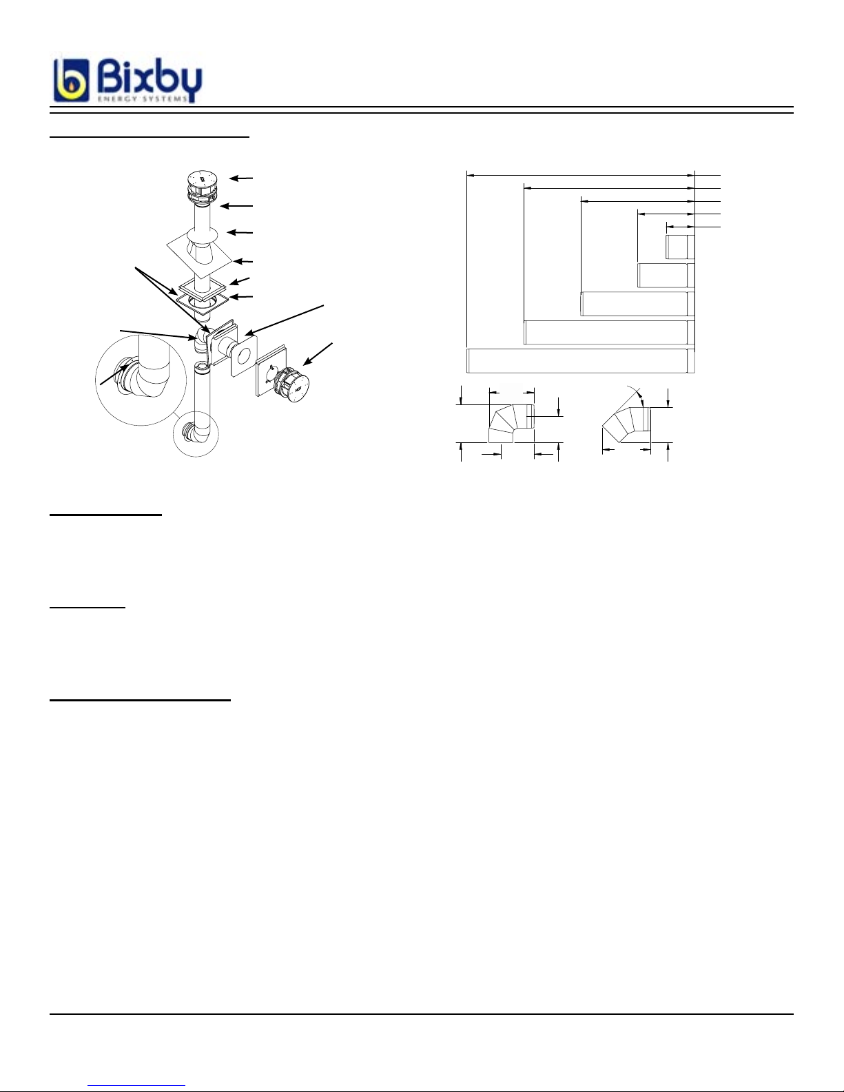
VENTING COMPONENTS
48 in. (122 cm)
36 in. (91 cm)
24 in. (61 cm)
12 in. (30 cm)
6 in. (15 cm)
Starter Collar
Figure 5
Decorative
Collar
Elbow
Vertical Vent Cap
Vent Pipe
Storm Collar
Roof Flashing
Ceiling firestop support
Ceiling Firestop
Thimble
Horizontal venting kit
8 in.
(20 cm)
Figure 6
9.5 in
(24 cm)
7 in.
(18 cm)
5.5 in
(14 cm)
45 deg
10.2 in
(26 cm)
7.4 in
(19 cm)
INSPECTIONS
The use of pelletized fuel does not eliminate the need for inspection and cleaning. During the heating season,
inspect monthly.
PERMITS
Contact your local building officials, fire officials, or the authority having jurisdiction about restrictions, permits,
and inspection requirements in your area.
VENT MAINTENANCE
• It is essential to have your venting and vent cap cleaned every year (each Spring) to remove soot
build up. If you have doubts about your ability to clean it, contact a professional chimney sweep. Use a
plastic, wood, or flexible steel brush. Do not use a stiff brush that will scratch the stainless steel liner of
your system.
• Bixby Direct Vent systems must be installed so that access is provided for inspection and cleaning.
• The vent system should be inspected at least once every month during the heating season.
• Chemical cleaners must be used with great caution. Use only those which are absolutely guaranteed not to
corrode or have any other harmful effects.
• In case of fire, shut off appliance and call your Fire Department. Do not use the appliance or vent until it
has been inspected for possible damage.
• Due to the nature of solid fuels and their production of ash, Bixby Energy Systems is not responsible for
flue by-products that might discolor roofs or walls.
10
2020866 REV A
 Loading...