


Compressor module screw compressors
Translation of the original document
English....................................................................................................................................................... 2
Verdichtermodul für Schraubenverdichter
Originaldokument
Deutsch ..................................................................................................................................................... 17
ST-150-2
CM-SW-01
Electrically skilled installer
Elektrisch unterwiesener Monteur

Table of contents
1 Introduction............................................................................................................................................................3
2 Safety ....................................................................................................................................................................3
2.1 Authorized staff..............................................................................................................................................3
2.2 Residual risks ................................................................................................................................................3
2.3 Safety references...........................................................................................................................................3
2.3.1 General safety instructions ................................................................................................................ 3
3 Technical data .......................................................................................................................................................4
4 Control and monitoring functions...........................................................................................................................6
4.1 Control functions............................................................................................................................................6
4.2 Monitoring and protective functions ...............................................................................................................6
5 Electrical connection..............................................................................................................................................7
5.1 Schematic wiring diagram for CSW105 .........................................................................................................7
5.2 Schematic wiring diagram for OS.95 .............................................................................................................9
5.3 Wiring in the state of delivery.......................................................................................................................11
5.4 High pressure limiter....................................................................................................................................11
6 Connecting cables ............................................................................................................................................... 11
6.1 Required electrical connections to CM-SW-01 ............................................................................................11
6.2 Optional electrical connections ....................................................................................................................12
6.3 Connecting system controller ......................................................................................................................12
6.3.1 Control via Modbus interface ...........................................................................................................12
6.3.2 Control via analogue signal.............................................................................................................. 12
6.4 Connecting operation monitoring via the BEST SOFTWARE .....................................................................12
7 Protective functions .............................................................................................................................................13
8 Monitoring the operating parameters using the BEST SOFTWARE ...................................................................15
8.1 Communication via the BEST SOFTWARE ................................................................................................15
8.2 Configuring CM-SW-01 with the BEST SOFTWARE ..................................................................................15
8.2.1 Selecting the motor start function .................................................................................................... 16
8.2.2 Setting the current time.................................................................................................................... 16
8.2.3 Changing the limit values for high and low pressure ....................................................................... 16
8.2.4 Configuring a spare part .................................................................................................................. 16
8.3 Data log .......................................................................................................................................................16
ST-150-22

1 Introduction
2.2 Residual risks
The CM-SW-01 compressor module integrates the entire electronic periphery of the compressor:
The CM-SW-01 monitors the essential operating parameters of the screw compressor and protects it from
operation under critical conditions. The module continuously controls the compressor depending on the capacity requirements of a superior system controller. It controls the capacity and, depending on the compressor
type, the internal volume ratio (Vi), the oil heater and
optional oil return. The module provides voltage supply
for the associated solenoid valves. It ensures an unloaded compressor start and controls the activation and
deactivation of the motor contactors during the start.
Additional time relays are not required.
During the operation, numerous operating data of the
compressor can be tracked using the BEST
SOFTWARE for example, the position in the application
limits diagram. These data are recorded and allow the
system operation to be diagnosed. 4 coloured LEDs indicate the operating condition of the compressor module.
This Technical Information describes the control and
monitoring functions, the electrical connection of the
compressor module and the communication with the
BEST SOFTWARE. For detailed information on Modbus programming and further technical data, see Reference Guide SG-160.
2 Safety
Compressors and electronic accessories may present
unavoidable residual risks. This is why any person
working on this device must carefully read this document!
The following regulations shall apply:
• the relevant safety regulations and standards (e.g.
EN378, EN60204 and EN60335),
• generally accepted safety rules,
• EU directives,
• national regulations.
2.3 Safety references
are instructions intended to prevent hazards. Safety references must be stringently observed!
NOTICE
Safety reference to avoid situations which may
result in damage to a device or its equipment.
CAUTION
Safety reference to avoid a potentially hazardous situation which may result in minor or moderate injury.
WARNING
Safety reference to avoid a potentially hazardous situation which could result in death or serious injury.
Compressors and compressor module have been built
in accordance with state-of-the-art methods and current
regulations. Particular importance was placed on user
safety.
The notes given in the Operating Instructions of the
compressor must be followed in addition to this Technical Information.
Always keep the operating instructions and this technical information in the vicinity of the refrigeration system during the whole lifetime of the compressor.
2.1 Authorized staff
All work done on the compressors, the refrigeration
systems and their electronic accessories may only be
performed by qualified and authorized personnel who
have been trained and instructed accordingly. The local
regulations and guidelines will apply with respect to the
qualification and expertise of the specialists.
DANGER
Safety reference to avoid an imminently hazardous situation which may result in death or serious injury.
2.3.1 General safety instructions
WARNING
Risk of electric shock!
Before working on the module housing and
electrical lines: Switch off the main switch and
secure it against being switched on again!
Close the module housing before switching on
again!
ST-150-2 3

NOTICE
The compressor module may be damaged or
fail!
Never apply any voltage to the terminals of CN7
to CN12 – not even for test purposes!
The voltage applied to the terminals of CN13
must not exceed 10V!
The voltage applied to terminal 3 of CN14 must
not exceed 24V! Do no apply voltage to the
other terminals!
Compressor module
Operating voltage 115 .. 230V +10%/-15%, 50/60Hz, max. 600VA
Required fuse (F3) 4 A time-lag at 230V / 8Atime-lag at 115V
Inputs, outputs and peripheral devices
Relay outputs for motor contactors
Input for release signal Terminal strip CN2, terminal 3
Signal output "collective
fault" (H10)
Connection for high pressure
switch (F5)
Terminal strip CN2, terminals 1 and 2
Maximum continuous current 2.5A
Switching voltage 240VAC
Maximum switching current 2.5A
Switching capacity 300VA inductive (NC contact: D300, NO contact:C300)
115 .. 230V +10%/-15%, 50/60Hz, max. 2,5A
Terminal strip CN2, terminal 4
115 .. 230V +10%/-15%, 50/60Hz, max. 2,5A (C300)
Terminal strip CN3
115 .. 230V +10%/-15%, 50/60Hz, max. 2,5A
Never apply voltage to the voltage outputs, not even for
testing.
3 Technical data
HS. and OS. compressors
Voltage supply of the optional
solenoid valve in the oil return
line (Y9)
CS.105
Oil heater (R1)
All screw compressors
Voltage supply of the solenoid
valves for capacity control and
Vi slider
Terminal 1: Output, NO contact
Terminal 2: Input
Terminal strip CN4
Output with overload protection, voltage output corresponds to the selected operating voltage
Semiconductor switch, not potential free
Use a solenoid coil with maximum power consumption of 12W at 230V / 14W
at 115V.
Terminal strip CN4
Output with overload protection, voltage output corresponds to the selected operating voltage
Semiconductor switch, not potential free
Use an oil heater with maximum power consumption of 300W at 230V. The
output is only suitable for oil heater connection at 230V supply voltage.
Terminal strip CN6
Output with overload protection, voltage output corresponds to the selected operating voltage
Semiconductor switch, not potential free
All solenoid valves are included in the extent of delivery of the compressor.
Use only original spare parts!
ST-150-24

All screw compressors
Analogue signal for capacity
control
All screw compressors
Modbus connection
Connection cables
Connection cable for power
connections : compressor module and peripheral devices
Connection cable for control
and sensor signals
Available cable bushings in the
module housing
Terminal strip CN13
0 .. 10 VDC, ±2% at 100%
at max. 1mA
Terminal strip CN14
Modbus RTU, RS485
Terminal strips CN1 to CN6
The terminals are suitable for max. 2.5mm2 (AWG12)
Voltage output corresponds to the selected operating voltage
Select the cable cross-sections in accordance with the local regulations!
Use copper cables with a sheath quality suitable for at least 85°C. Select the
cable quality according to the place of installation, e.g. UV- and/or oil-resistant.
0 .. 10V
Terminal strips CN7 to CN14
The terminals are suitable for max. 1.5mm2 (AWG16)
Select the cable cross-sections in accordance with the local regulations!
Use copper cables with a sheath quality suitable for at least 85°C. Select the
cable quality according to the place of installation, e.g. UV- and/or oil-resistant.
OS.95:
Screwed joints:
1xM20x1,5 for 1 cable with clamping range Ø8 to 13mm
1xM16x1,5 for 1 cable with clamping range Ø5 to 10mm
Blind caps: 1xM25x1,5 and 1xM16x1,5
Cable plug for 1 cable with Ø5mm
CS.105:
Screwed joints: 1xM20x1,5 for 1 cable with clamping range Ø8 to13mm
Blind cap: 1xM16x1,5
Cable plugs for 2 cables with Ø7mm and 2 cables with Ø5mm
Characteristics of the compressor module
Enclosure class Module housing in its state of delivery: IP65
Compressor module without module housing: IP00
Internal overcurrent protection Terminal strips CN4 to CN6
This fuse protects the CM-SW-01 against short-circuit if a short-circuit occurs
in one of the connected solenoid valves or in the oil heater of the CS.105.
An alarm message is output in the BEST SOFTWARE or via Modbus.
Place of installation Allowable ambient temperature: -30°C .. +70°C
Allowable relative humidity: 5% .. 95% (EN60721-3-3 Classes 3K3 and 3C3)
Maximum allowable altitude: 2000m
EMC The compressor module complies with the EU EMC directive 2014/30/EU
Interference immunity
EN61000-6-1:2007, Immunity for residential, commercial and light-industrial
environments
EN61000-6-2:2005, Immunity for industrial environments
Emitted interference
ST-150-2 5

EN61000-6-3:2007 +A1:2011, emission standard for residential, commercial
and light-industrial environments
The compressor module internally supplies the voltage
to peripheral devices (solenoid valves, slider position
indicator, oil monitoring and/or oil heater) and to the terminal strips CN7 to CN12.
Phase monitoring fuse F24
The HS. and CS. compressors incorporating the compressor module are equipped with the F24 fuse in the
terminal box. It protects the phase monitoring lines.
Such a fuse is also required with open compressors
between module housing and motor terminal box when
the phase monitoring function of the compressor module is used.
Technical data of the installed fuse:
• Rated current 1A
• Release speed FF (very quick acting)
• Rated breaking capacity of 50kA at 700VAC
• Dimensions 6.3 x 32mm
4 Control and monitoring functions
4.1 Control functions
The CM-SW-01 compressor module controls the capacity control and the adjustment of the internal volume
ratio (Vi).
Capacity control
Oil return in OS. and HS. compressors
A option the compressor module may measure out the
returned oil amount. It triggers the solenoid valve in the
oil return line (Y9).
Oil heater in CS. compressors
The module maintains the oil temperature 20K above
the saturation temperature of the refrigerant. Also during standstill , it switches the oil heater on and off. This
increases the total efficiency of the system.
Control of the motor contactors at compressor start
The compressor control module controls the activation
and deactivation times of the motor contactors.
Star-delta motor: The contact at terminal CN2:2 (K1
Control) closes 1second after the release signal and
reopens after further 2seconds. The contact at terminal
CN2:1 (K2 Control) closes 1.5seconds after the release signal and remains closed until the compressor is
shut off.
Motor for direct on-line start: The contact at terminal
CN2:2 (K1 Control) closes 1second after the release
signal and reopens when the compressor is shut off.
The contact at terminal CN2:1 (K2 Control) is not used.
For soft start and operation with frequency inverter,
only one motor contactor is required.
In case of open drive compressors or spare part modules the time relay control needs to be set with the
BEST SOFTWARE according to the motor used, see
chapter Selecting the motor start function, page 16.
The module continuously adjusts the compressor capacity according to the set point of the superior system
controller. With the HS.95, OS.95 and CSW105 compressors, this is done by switching both solenoid valves
CR+ and CR- of the capacity control slider or with other
compressors, by switching the 4 capacity regulators.
Adjustment of the internal volume ratio (Vi)
The module automatically sets the most suitable Vi in
each case. To this end, it evaluates the slider position
and the current operating conditions by means of integrated algorithms.
Unloaded compressor start
When the device is switched off, the compressor module positions the control slider and the Vi slider in a way
to ensure an unloaded start of the compressor.
4.2 Monitoring and protective functions
The compressor module monitors the signals from several sensors located on the compressor:
Monitored
function
Application
limits:
Condensing and
evaporation temperature
Low pressure
High pressure
Compressor
All
All Low pressure transmitter
All High pressure transmitter
Measuring sensor
Low pressure and high
pressure transmitters (B7
and B6)
(B7)
(B6)
ST-150-26

Monitored
function
Discharge
gas tem-
Com-
Measuring sensor
pressor
HS./OS. Discharge gas temperature
sensor (R2)
perature
Oil temper-
CSW105 Oil temperature sensor (R2)
ature
Oil supply HS./OS. Opto-electronic oil monitor-
ing (F7)
Minimum
oil level
Motor temperature
Rotation
direction
CSW105 Opto-electronic oil monitor-
ing (F8)
HS./
CSW105
HS./
CSW105
PTC sensor in motor windings (R3..8)
Instrument leads on the
bolts of the motor power
supply
Unloaded
All Slider position indicator
start
The compressor module compares the measured values with programmed data, sending signals via Modbus and indicating the operating condition by means of
differently coloured LEDs. The compressor will be shut
down in case of operation beyond the application limits,
lack of oil, excessive motor temperature, wrong rotation
direction or critical motor start, see chapter Protective
functions, page 13.
5 Electrical connection
Keep the compressor module energized when the motor is not running. This ensures an unloaded start. With
CS. compressors, the module activates the oil heater, if
necessary, thus ensuring the lubricity of the oil even
after a long standstill period.
De-energize the module only if you plan a long standstill period of the compressor or for maintenance purposes.
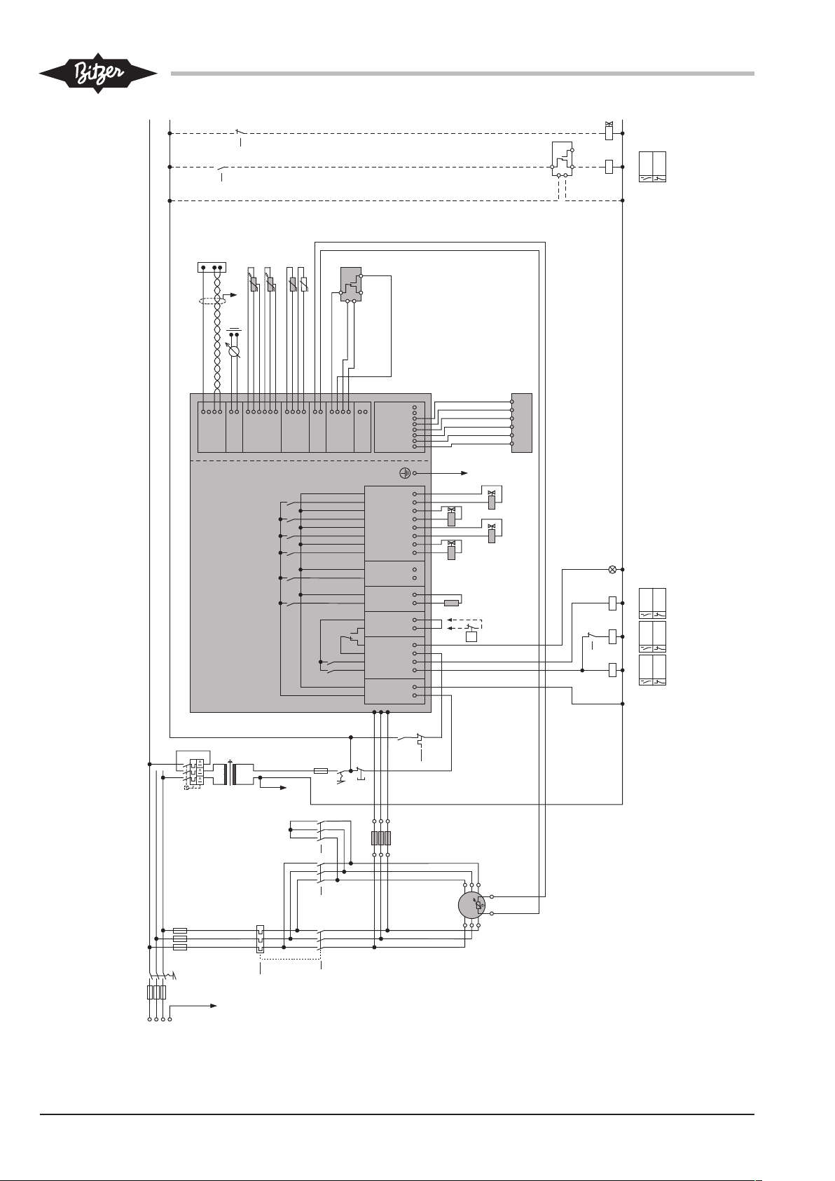
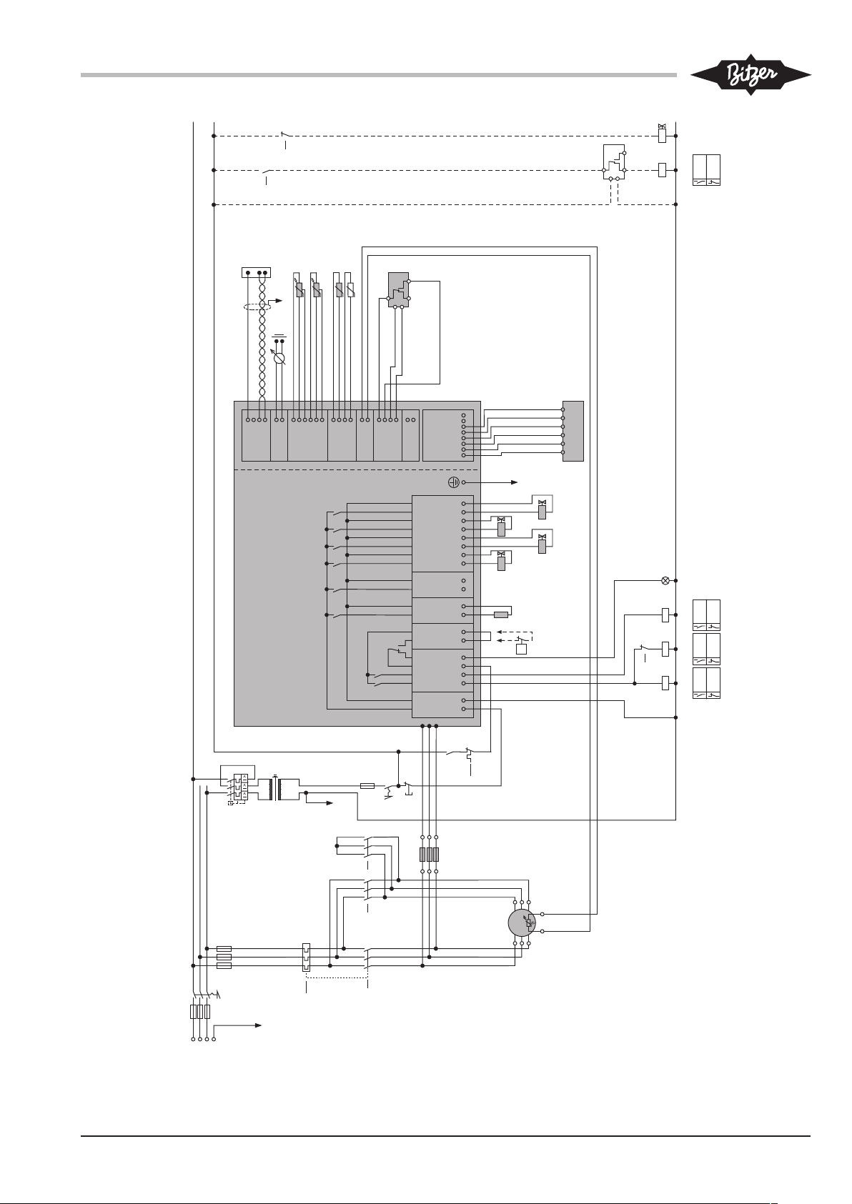
5.1 Schematic wiring diagram for CSW105
Abbr. Component
B2 Superior controller
B5 Slider position indicator (SPI)
B6 High pressure transmitter
B7 Low pressure transmitter
F1 Main fuse
F2 Compressor fuse
F3 Control circuit fuse
F5 High pressure switch
Abbr. Component
F8 Oil level switch (minimum oil level)
F13 Overload protective device
F15
Oil level switch (maximum oil level, option
of
the compressor)
F17 Control transformer fuse
F24 Phase monitoring fuse
H10 Light "collective fault"
K1 Main contactor (star-delta)
K2 Delta contactor (star-delta)
K3 Star contactor (star-delta)
K4 Auxiliary relay
M1 Compressor
Q1 Main switch
R1 Oil heater
R2 Oil temperature sensor
R3..8 Temperature sensor in the motor
R10 Optional temperature sensor
S1 Control switch (on/off)
S2 Reset of CM-SW-01
T1 Control transformer (example for 230V, re-
quired according to EN60204-1)
Y1 Solenoid valve "capacity regulator CR+"
Y2 Solenoid valve "capacity regulator CR-"
Y6 Solenoid valve "ECO"
Y11 Solenoid valve "Vi slider +"
Y12 Solenoid valve "Vi slider -"
Y13 Solenoid valve "oil return from the flooded
evaporator"
Tab.1: Legend for CSW105 schematic wiring diagram with CMSW-01 and star-delta start
The CSW105 compressor has a connection for oil and
gas return as an option for systems with flooded evaporator. For connection position, see Operating Instructions SB-170, chapter Mounting, Connections and dimensional drawings, position 17. The electrical integration of this option is shown in the paths 24 to 26. The
switching times of the solenoid valve must be controlled
by the superior system controller and individually tested
for each system.
ST-150-2 7
1 2 3 4
CN1
L N
CN2
K2control
Supply
Supply
K1control
RelayC
RelayNC
CN3
HPS
HPS
CN4
Control1
Control1
CN5
Control2
Control2
CN6
CR+
CR+
CR–
CR–
Vi+
Vi+
Vi–
Vi–
5 6 7 8
CN7
1 2 3 4 1 2
CN9
CN10
1 2 3 4 5 6
CN12
1 2 3 4
CN11
1 2
CN13
1 2 3 4
CN14
24 upVS
GND
Signal
GND
PTC
PTC
Signal
GND
Signal
GND
5 upVS
Signal
GND
5 upVS
Signal
GND
Input
GND
Data+
Data–
Sup In
GND
St/Sp-
24V Sup
GND
Signal
GND
St/Sp+
INITINIT+
21 3 4 1 2 1 N 1 N 1 N 3 N 5 N 7 N
CM SW- -01
4321 876
5
13
1211
109
14
15
16
17
18 19 20
21 22 23 24 2625
S2
F2
L1L2L3
PE
F1
Q1
1
0
K1
10
K2
11
F13
8
K3
12
F17
230V
T1
F3 4A T
PE
S1
01
F13
2
H10
2/2/2
K1
K2
K3
12
Y11
Y2
Y12
4/4/4/25
orange
F8
Modbus
RS485
PE
0 .. 10V
1 2
CT-1
CT-2
CN8
B5
5/5/5K311
PEF5
P>
Y1
R1
230 V
123
789
T1
R3..8
T2
blue/blau/bleu
brown/braun
black/schwarz
F24
321
grey/grau/gris
brown/braun/marron
pink
rosa
rose
blue/blau/bleu
blue/blau/bleu
brown/braun/marron
grey/grau/gris
yellow/gelb/jaune
pink/rosa/rose
green/grün/vert
M 3~
M1
1
2
K4
K2
11
schwarz/black/noir
B6B7R2
R10
blau/blue/bleu
schwarz/black/noir
braun/brown/marron
blau/blue/bleu
braun/brown/marron
blau/blue/bleu
braun/brown/marron
1A FF
F15
grey
grau
gris
brown/braun/marron
blue/blau/bleu
orange
orange
orangepink
rosa
rose
Y13
B2
26
K4
25
Fig.1: CSW105 with CM-SW-01 and star-delta start
ST-150-28

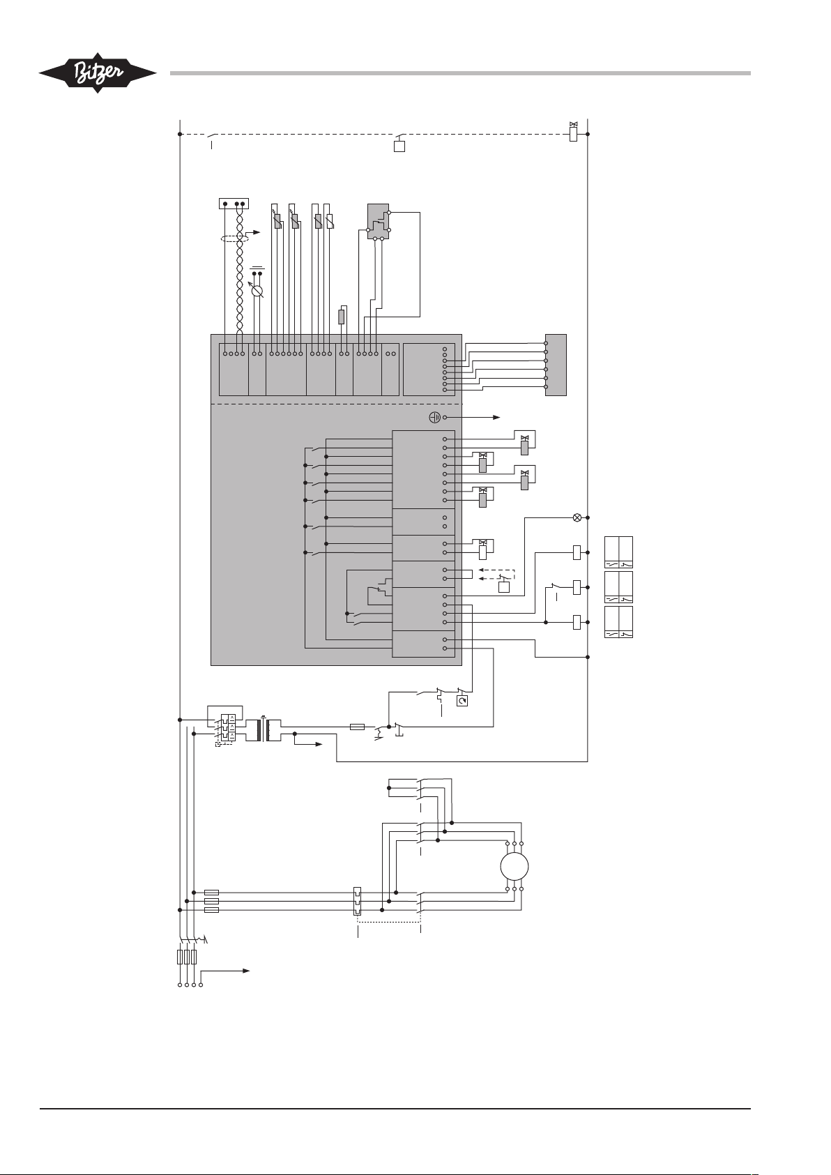
5.2 Schematic wiring diagram for OS.95
Abbr. Component
B2 Superior controller
B5 Slider position indicator (SPI)
B6 High pressure transmitter
B7 Low pressure transmitter
F1 Main fuse
F2 Compressor fuse
F3 Control circuit fuse
F5 High pressure switch
F7 Oil flow switch
F12 Control unit ECO
F13 Overload protective device
F16 Rotation direction monitoring
F17 Control transformer fuse
H10 Light "collective fault"
K1 Main contactor (star-delta)
K2 Delta contactor (star-delta)
K3 Star contactor (star-delta)
M1 Compressor
Q1 Main switch
R2 Discharge gas temperature sensor
R10 Optional temperature sensor
S1 Control switch (on/off)
S2 Reset of CM-SW-01
T1 Control transformer (example for 230V, re-
quired according to EN60204-1)
Y4 Solenoid valve "capacity regulator CR+"
Y5 Solenoid valve "capacity regulator CR-"
Y8 Solenoid valve “ECO” (option of compressor)
Y9 Solenoid valve "oil return”
Y11 Solenoid valve "Vi slider +"
Y12 Solenoid valve "Vi slider -"
Tab.2: Legend for OS.95 schematic wiring diagram with CM-SW-01
and star-delta start
The schematic wiring diagram shows a star-delta motor. OS.95 compressors can also be operated with
other motors. In this case, the time relay control suitable for the motor type must be set using the BEST
SOFTWARE, see chapter Selecting the motor start
function, page 16.
ST-150-2 9
1 2 3 4
CN1
L N
CN2
K2control
Supply
Supply
K1control
RelayC
RelayNC
CN3
HPS
HPS
CN4
Control1
Control1
CN5
Control2
Control2
CN6
CR+
CR+
CR–
CR–
Vi+
Vi+
Vi–
Vi–
5 6 7 8
CN7
1 2 3 4 1 2
CN9
CN10
1 2 3 4 5 6
CN12
1 2 3 4
CN11
1 2
CN13
1 2 3 4
CN14
24 upVS
GND
Signal
GND
PTC
PTC
Signal
GND
Signal
GND
5 upVS
Signal
GND
5 upVS
Signal
GND
Input
GND
Data+
Data–
Sup In
GND
St/Sp-
24V Sup
GND
Signal
GND
St/Sp+
INITINIT+
21 3 4 1 2 1 N 1 N 1 N 3 N 5 N 7 N
CM SW- -01
4321 876
5
13
1211
109
14
15
16
17
18 19 20
21 22
S2
F2
L1L2L3
PE
F1
Q1
1
0
K2
11
M3~
K3
12
F17
230V
T1
F3 4A T
PE
S1
01
F13
2
B2
H10
W1
V1
U1
V2
U2
W2
M1
2/2/2
K1
K2
K3
12
Y11
Y5
Y12
4/4/4/31
grey/grau/gris
brown/braun/marron
orangepink
rosa
rose
blue/blau/bleu
F7
Modbus
RS485
PE
0 .. 10V
blue/blau/bleu
brown/braun/marron
1 2
CT-1
CT-2
CN8
B5
5/5/5K311
PE
F5
P>
Y9 Y4
grey/grau/gris
yellow/gelb/jaune
pink/rosa/rose
green/grün/vert
F16
K1
10
F13
8
B6B7R2
R10
blau/blue/bleu
schwarz/black/noir
braun/brown/marron
blau/blue/bleu
braun/brown/marron
blau/blue/bleu
braun/brown/marron
schwarz/black/noir
F12
...
31
K2
11
Y8
P<
1k
Fig.2: OS.95 with CM-SW-01 and star-delta start
ST-150-210

5.3 Wiring in the state of delivery
Components shown in grey in the schematic wiring diagram are included in the extent of delivery of the corresponding compressor. In the state of delivery of the
compressor, these components are completely installed and wired. Modification to these components or
their wiring is not required.
Dashed components or current paths represent compressor options. Components connected to the compressor module that are shown in white are also options which are not included in the extent of delivery.
high pressure transmitter (B6) does not sufficiently ensure the safety cut-out function. The high pressure limiter (F5) should preferably be connected to terminal
strip CN3 instead of the bridge.
The installation of a low pressure limiter is not necessary, depending on local regulations. The compressor
module is provided with an automatic low pressure cutout function.
6 Connecting cables
CSW105: pre-fitted components
• Slider position indicator (B5)
• Solenoid valves for capacity control and Vi (Y1, Y2,
Y11 and Y12)
• Low pressure and high pressure transmitters (B7
and B6)
• Oil temperature sensor (R2)
• Monitoring of the minimum oil level (OLC-D1, F8)
• Oil heater (R1) at 230V voltage supply
• Motor temperature monitoring (R3 to R8)
• Rotation direction monitoring
OS.95: pre-fitted components
• Slider position indicator (B5)
• Solenoid valves for capacity control and Vi (Y4, Y5,
Y11 and Y12)
• Low pressure and high pressure transmitters (B7
and B6)
• Discharge gas temperature sensor (R2)
• Oil monitoring (OLC-D1, F7)
Electrically connect the compressor module in accordance with the schematic wiring diagrams. Observe the
safety standards EN60204-1, IEC60364 and national
safety regulations.
WARNING
Risk of electric shock!
Before working on the module housing and
electrical lines: Switch off the main switch and
secure it against being switched on again!
Close the module housing before switching on
again!
NOTICE
The compressor module may be damaged or
fail!
Never apply any voltage to the terminals of CN7
to CN12 – not even for test purposes!
The voltage applied to the terminals of CN13
must not exceed 10V!
The voltage applied to terminal 3 of CN14 must
not exceed 24V! Do no apply voltage to the
other terminals!
Never apply voltage to the voltage outputs, not even for
testing.
Voltage supply of the peripheral devices
The compressor module internally supplies the voltage
to the terminal strips CN7 to CN12 and to peripheral
devices (solenoid valves, oil monitoring, slider position
indicator and with CSW105, also phase monitoring and
230V oil heater).
5.4 High pressure limiter
According to EN378 directive, each compressor must
be provided with a high pressure limiter (F5) for safety
cut-out in the safety chain. Depending on the refrigerant charge, it must be designed as a safety pressure
cut-out or only as pressure cut-out. The software-controlled monitoring of the compressor module via the
ST-150-2 11
6.1 Required electrical connections to CM-SW-01
• Power connection to terminal strip CN1
– Terminal 1: L
– Terminal 2: N
• Command for compressor start (release signal from
the superior system controller, B2)
The release signal from the superior controller is
provided in path8 as the first link of the safety chain.
This release information must be passed on to the
compressor module. It activates the time relay control for the motor contactors K1, K2 and K3.
– Connect the safety chain (release signal) to ter-
minal strip CN2, terminal3.
– Integrate the compressor module as the last link
CR
0 2 4 6 8 10 12
U [V]
0 .. 10 V
100%
25%
2,5
into the safety chain.
• Connection to terminal strip CN13, terminals 1 and
2.
• Control signal from the system controller (nominal
value for capacity control)
– Connect the Modbus cable to terminal strip CN14.
– Or connect the analogue signal to terminal strip
CN13.
• High pressure limiter
– Connect it preferably to terminal strip CN3 instead
of the bridge, see chapter Schematic wiring diagram for CSW105, page 7 and see chapter
Schematic wiring diagram for OS.95, page 9.
– Alternatively, it can also be integrated into the
safety chain, in that case after the compressor
module.
6.2 Optional electrical connections
To CN4 with OS.95
With OS.95, the solenoid valve in the oil return line (Y9)
can be connected to terminal strip CN4. It is switched
by the compressor module. If this solenoid valve is
triggered by the superior controller, it must be ensured
that the solenoid valve is closed during compressor
standstill and opens only 3s after compressor start.
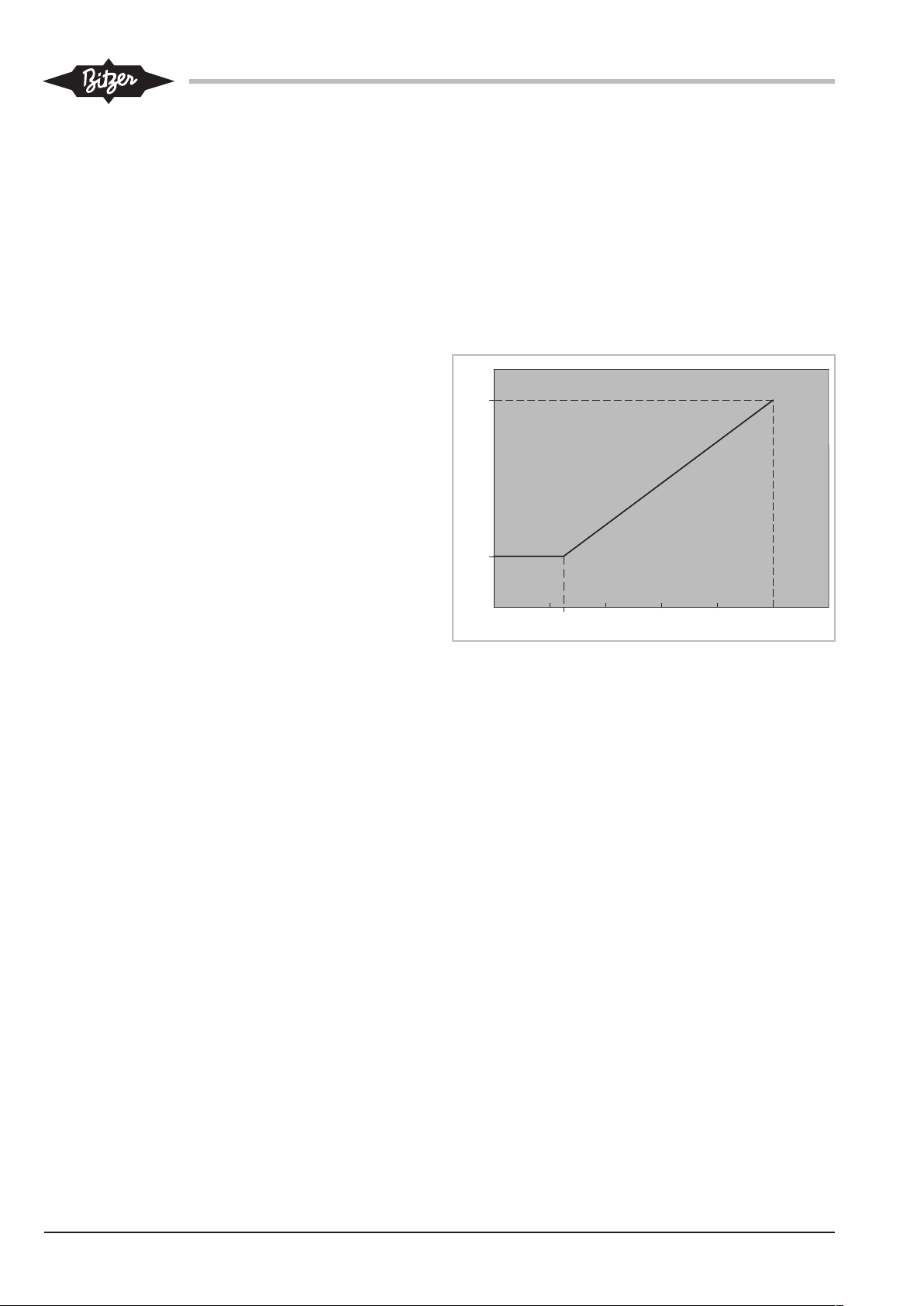
• Control signal: 0 to 10V DC voltage of an analogue
output of the system controller
• As an alternative, a control signal between 4 and
20mA may be connected to terminals 1 and 2. Connect a 400 Ω resistor in series in this case.
• Control accuracy: ±0.5% at 100%
• Linear control characteristic, see figure.
Fig.3: Control characteristics
With the CSW105 with 230V voltage supply, the oil
heater (standard extent of delivery) which is switched
on and off if needed by the compressor module is connected here.
6.3 Connecting system controller
6.3.1 Control via Modbus interface
Plug or connect the cable to terminal strip CN14, see
chapter Schematic wiring diagram for CSW105, page 7
or see chapter Schematic wiring diagram for OS.95,
page 9.
In this case, the operating parameters can be monitored via Bluetooth by means of the BEST
SOFTWARE.
6.3.2 Control via analogue signal
The compressor capacity may be regulated via a DC
voltage signal. This type of control is mainly suitable for
systems with simple controllers which are equipped
with an output for 0 to 10V and a relay, and if the terminal strip CN14 is used for the BEST SOFTWARE.
6.4 Connecting operation monitoring via the BEST
SOFTWARE
The BEST SOFTWARE accesses the compressor
module via the Bluetooth interface, see chapter Communication via the BEST SOFTWARE, page 15. This
interface is deactivated in some non-European countries.
◦ If the Bluetooth interface should not be used:
• Connect the BEST interface converter to terminal
strip CN14 (Modbus).
In this case, the capacity control must be preset via the
analogue signal on terminal strip CN13.
ST-150-212

7 Protective functions
Warning
The green LED is on during normal operation. The
LEDs can be seen through a sight glass on the right
side of the module housing.
Before the measured value of a sensor reaches a critical threshold, the compressor module outputs an alarm
signal via the Modbus RS485 interface (CN14). In this
case, the yellow LED lights up. Once a measured value
is considerably outside the allowable range, the compressor module will immediately switch off the motor.
The red LED lights up.
The blue LED lights up when data are transmitted via
the Modbus or the Bluetooth interface.
Depending on the measured values, up to 3 alarm
levels are defined. These alarms are recorded and displayed using the BEST SOFTWARE. The alarm levels
make it possible to programme a system controller in a
way that allows the compressor to be controlled within
the application limits.
Monitored function Time delay
after com-
pressor start
CSW105
Low pressure --- --- --- < -0.2bar negative pressure
Warning Critical alarm Fault
The warning threshold is exceeded when the application limit is almost reached. The yellow LED lights up.
This is a software message, not a safety reference. The
warning refers exclusively to the critical operating condition of the compressor.
Critical alarm
The cut-out value is exceeded. The yellow LED lights
up. If the corresponding measured value does not drop
again within the corresponding time delay, the compressor will be switched off. This cut-out is classified as
fault in the alarm list.
Fault
The cut-out value has been exceeded too much or for
too long. The compressor is switched off. The red LED
lights up.
(corresponds to <0.8bar absolute pressure at sea level)
CM-SW-01 locks out immediately.
High pressure --- --- --- > 21bar excess pressure (cor-
responds to >22bar absolute
pressure at sea level)
CM-SW-01 locks out immediately.
Application limits
(Condensing temperature,
evaporation temperature)
Oil temperature --- >115°C --- >120°C
Minimum oil level --- 5s --- CM-SW-01 locks out after 90
Rotation direction --- --- --- CM-SW-01 locks out immedi-
OS.95
120s <2K within the
application limits
>2K outside
the application
limits
CM-SW-01
locks out after
30 seconds.
>4K outside the application limits
CM-SW-01 locks out immediately.
CM-SW-01 locks out immediately.
seconds.
ately.
ST-150-2 13

Monitored function Time delay
after compressor start
Low pressure --- --- --- < -0.6bar negative pressure
High pressure --- --- --- > 28bar excess pressure (cor-
Application limits
(Condensing temperature,
evaporation temperature)
Discharge gas temperature
Oil supply 15s --- --- CM-SW-01 locks out after 5
120s <2K within the
--- >95°C --- >100°C
Warning Critical alarm Fault
(corresponds to <0.4 bar absolute pressure at sea level)
CM-SW-01 locks out immediately.
responds to >29bar absolute
pressure at sea level)
CM-SW-01 locks out immediately.
application limits
>2K outside
the application
limits
CM-SW-01
locks out after
30 seconds.
>4K outside the application limits
CM-SW-01 locks out immediately.
CM-SW-01 locks out immediately.
seconds.
Reset
Interrupt the voltage supply (L/N) for at least 5 s. All
system related alarms except the motor temperature
monitoring may be reset also via Modbus command or
the BEST SOFTWARE. With the the BEST
SOFTWARE by using the RESET button in the ALARMS
menu.
ST-150-214

8 Monitoring the operating parameters using the
BEST SOFTWARE
The BEST SOFTWARE offers comprehensive access
to all operating data and control parameters and can be
downloaded for free from the BITZER website
(www.bitzer.de).
8.1 Communication via the BEST SOFTWARE
Requirements
• Mobile device
– with the operating system Windows7 or newer
– with Bluetooth interface or USB port
– with BEST SOFTWARE installed
The BEST SOFTWARE can be downloaded for
free from the BITZER website (www.bitzer.de).
• In case of communication via the USB port:
– Plug the BEST interface converter into the com-
pressor module (CN14) and the mobile device.
– Compressor control via the analogue connection
(CN13). It is not possible to perform capacity control simultaneously via the Modbus connection.
Setting up communication
• Switch on the mobile device and start BEST
SOFTWARE (1).
• Click the NEW button (2).
• Select CM-SW-01 (3).
• Click the CONNECT button (4).
The following selection appears: BEST CONVERTER or
BLUETOOTH.
• Selection BEST CONVERTER:
Click the CONNECT button.
Fig.4: Connecting the CM-SW-01 with the BEST SOFTWARE
8.2 Configuring CM-SW-01 with the BEST SOFTWARE
In its state of delivery, the compressor module CMSW-01 is completely pre-configured for use with the respective compressor.
Check all parameters in menu CONFIGURATION and
change them if necessary. Check particularly these settings:
• MOTOR STARTER FUNCTION for the time relay control of
the motor contactors
• REFRIGERANT
• DATE
• TIME
The compressor module is now connected to the
mobile device.
• Selection BLUETOOTH:
All available devices are listed.
• Select the CM-SW-01.
• Click the CONNECT button.
• Enter Bluetooth password. Factory setting from firmware version 2.6.58.00 on: "8670", previous versions: "2"
The CONFIGURATION menu appears with the MAIN SETUP
window. The compressor module is now connected to
Fig.5: Menu CONFIGURATION
the mobile device.
ST-150-2 15

8.2.1 Selecting the motor start function
8.3 Data log
The compressor module controls the activation and deactivation times of the motor contactors. The BEST
SOFTWARE can be used to choose between stardelta, part winding or direct on line start.
Adjustment in the BEST SOFTWARE:
• Set the suitable motor start function in the MOTOR
STARTER FUNCTION window of the MAIN SETUP menu.
The compressors starts 1second after the release signal of the superior system controller, in any case.
8.2.2 Setting the current time
Check the programmed date and time using the BEST
SOFTWARE:
• Check the CONFIGURATION menu, the MAIN SETUP window and the DATE and TIME lines.
• Correct the data if necessary.
8.2.3 Changing the limit values for high and low
pressure
In the state of delivery, the limit values for high pressure and low pressure cut-out are set for the respective
compressor. The pressure transmitters detect relative
pressures. Depending on the system design, these values may need to be adjusted. The high pressure can
not be increased further.
All monitored operating parameters and alarm messages are stored internally:
• All operating parameters in 5- or 10-second intervals
• Storage capacity: approx. 2 weeks in case of normal
operating behaviour
• Alarm messages and statistics of the last 365 days
This data can be exported using the BEST
SOFTWARE. These data enable analysis of the system
operation and provide detailed information for
troubleshooting, Operation monitoring with BEST
SOFTWARE.
Setting new limit values in the BEST SOFTWARE:
• Enter new limit values via CONFIGURATION, window
PROTECTIVE FUNCTIONS, in the lines HIGH PRESSURE
SWITCH: VALUE and LOW PRESSURE SWITCH: VALUE.
8.2.4 Configuring a spare part
If a CM-SW-01 has been replaced, the specific compressor parameters must be set. The time relay control
is preset for star-delta start.
• Connect the mobile device to the new CM-SW-01.
• Open BEST SOFTWARE and select the new CMSW-01.
• Update firmware.
• Adjust all MAIN SETUPs in menu CONFIGURATION.
• Check all further parameters and adjust them, if necessary.
ST-150-216

ST-150-2 17

Inhaltsverzeichnis
1 Einleitung.............................................................................................................................................................19
2 Sicherheit.............................................................................................................................................................19
2.1 Autoriertes Fachpersonal.............................................................................................................................19
2.2 Restgefahren ...............................................................................................................................................19
2.3 Sicherheitshinweise .....................................................................................................................................19
2.3.1 Allgemeine Sicherheitshinweise ...................................................................................................... 19
3 Technische Daten................................................................................................................................................20
4 Steuer- und Überwachungsfunktionen ................................................................................................................22
4.1 Steuerfunktionen..........................................................................................................................................22
4.2 Überwachungs- und Schutzfunktionen ........................................................................................................23
5 Elektrischer Anschluss ........................................................................................................................................24
5.1 Prinzipschaltbild für CSW105 ......................................................................................................................24
5.2 Prinzipschaltbild für OS.95 ..........................................................................................................................26
5.3 Verkabelung im Auslieferungszustand ........................................................................................................28
5.4 Hochdruckschalter .......................................................................................................................................28
6 Kabel anschließen ............................................................................................................................................... 28
6.1 Erforderliche elektrische Anschlüsse an das CM-SW-01 ............................................................................28
6.2 Optionale elektrische Anschlüsse................................................................................................................29
6.3 Anlagenregler anschließen ..........................................................................................................................29
6.3.1 Steuerung über Modbus-Schnittstelle.............................................................................................. 29
6.3.2 Steuerung über Analogsignal........................................................................................................... 29
6.4 Betriebsüberwachung mit der BEST SOFTWARE anschließen..................................................................29
7 Schutzfunktionen ................................................................................................................................................. 30
8 Betriebsparameter mit der BEST SOFTWARE überwachen...............................................................................31
8.1 Kommunikation über die BEST SOFTWARE ..............................................................................................31
8.2 CM-SW-01 mit der BEST SOFTWARE konfigurieren .................................................................................32
8.2.1 Motoranlauffunktion auswählen .......................................................................................................32
8.2.2 Aktuelle Uhrzeit einstellen................................................................................................................ 32
8.2.3 Grenzwerte für Hoch- und Niederdruck ändern ............................................................................... 32
8.2.4 Ersatzteil konfigurieren .................................................................................................................... 33
8.3 Datenaufzeichnung......................................................................................................................................33
ST-150-218

1 Einleitung
2.2 Restgefahren
Das Verdichtermodul CM-SW-01 integriert die gesamte
elektronische Peripherie des Verdichters:
Das CM-SW-01 überwacht die wesentlichen Betriebsparameter des Schraubenverdichters und schützt ihn
vor Betrieb bei kritischen Bedingungen. Das Modul regelt den Verdichter stufenlos entsprechend der Leistungsanforderung eines übergeordneten Anlagenreglers. Es steuert die Leistungsregelung und je nach Verdichtertyp das interne Volumenverhältnis (Vi), die Ölheizung und optional die Ölrückführung. Das Modul liefert
die Spannungsversorgung für die zugehörigen Magnetventile. Es sorgt für einen entlasteten Verdichteranlauf
und steuert die Zu- und Abschaltung der Motorschütze
während des Anlaufs. Zusätzliche Zeitrelais werden dafür nicht benötigt.
Zahlreiche Betriebsdaten des Verdichters können mit
der BEST SOFTWARE während des Betriebs verfolgt
werden, beispielsweise die Position im Einsatzgrenzdiagramm. Diese Daten werden aufgezeichnet und erlauben eine Diagnose des Anlagenbetriebs. 4 farbige
LEDs signalisieren den Betriebszustand des Verdichtermoduls.
Diese Technische Information beschreibt die Steuerund Überwachungsfunktionen, den elektrischen Anschluss des Verdichtermoduls und die Kommunikation
mit der BEST SOFTWARE. Detaillierte Information zur
Modbus-Programmierung und weitere technische Daten siehe Reference Guide SG-150.
2 Sicherheit
Verdichter und Verdichtermodul sind nach dem aktuellen Stand der Technik und entsprechend den geltenden
Vorschriften gebaut. Auf die Sicherheit der Anwender
wurde besonderer Wert gelegt.
Zusätzlich zu dieser Technischen Information müssen
die Hinweise in der Betriebsanleitung des Verdichters
eingehalten werden.
Betriebsanleitung und diese Technische Information
während der gesamten Verdichterlebensdauer an der
Kälteanlage verfügbar halten!
2.1 Autoriertes Fachpersonal
Sämtliche Arbeiten an Verdichtern, Kälteanlagen und
deren elektronischem Zubehör dürfen nur von Fachpersonal ausgeführt werden, das in allen Arbeiten ausgebildet und unterwiesen wurde. Für die Qualifikation und
Sachkunde des Fachpersonals gelten die jeweils landesüblichen Vorschriften und Richtlinien.
Von Verdichtern und elektronischem Zubehör können
unvermeidbare Restgefahren ausgehen. Jede Person,
die an diesem Gerät arbeitet, muss deshalb dieses Dokument sorgfältig lesen!
Es gelten zwingend
• die einschlägigen Sicherheitsvorschriften und Normen (z.B. EN 378, EN 60204 und EN 60335),
• die allgemein anerkannten Sicherheitsregeln,
• die EU-Richtlinien,
• nationale Vorschriften.
2.3 Sicherheitshinweise
sind Anweisungen um Gefährdungen zu vermeiden. Sicherheitshinweise genauestens einhalten!
HINWEIS
Sicherheitshinweis um eine Situation zu vermeiden, die die Beschädigung eines Geräts oder
dessen Ausrüstung zur Folge haben könnte.
VORSICHT
Sicherheitshinweis um eine potentiell gefährliche Situation zu vermeiden, die eine geringfügige oder mäßige Verletzung zur Folge haben
könnte.
WARNUNG
Sicherheitshinweis um eine potentiell gefährliche Situation zu vermeiden, die den Tod oder
eine schwere Verletzung zur Folge haben könnte.
GEFAHR
Sicherheitshinweis um eine unmittelbar gefährliche Situation zu vermeiden, die eine schwere
Verletzung oder den Tod zur Folge hat.
2.3.1 Allgemeine Sicherheitshinweise
WARNUNG
Gefahr von elektrischem Schlag!
Vor Arbeiten im Modulgehäuse und an elektrischen Leitungen: Hauptschalter ausschalten
und gegen Wiedereinschalten sichern!
Vor Wiedereinschalten Modulgehäuse schließen!
ST-150-2 19

HINWEIS
Beschädigung oder Ausfall des Verdichtermoduls möglich!
An die Klemmen von CN7 bis CN12 keine
Spannung anlegen – auch nicht zum Prüfen!
An die Klemmen von CN13 maximal 10V anlegen!
An die Klemme 3 von CN14 maximal 24V, an
die anderen Klemmen keine Spannung anlegen!
Verdichtermodul
Betriebsspannung 115 .. 230V +10%/-15%, 50/60Hz, max. 600VA
erforderliche Sicherung (F3) 4Aträge bei 230V / 8Aträge bei 115V
Ein- und Ausgänge sowie Peripheriegeräte
Relaisausgänge für Motorschüt-zeKlemmleiste CN2, Klemmen 1 und 2
Dauerstrom max. 2,5A
Schaltspannung 240V∿
Schaltstrom max. 2,5A
Schaltleistung 300VA induktiv (Öffnerkontakt: D300, Schließkontakt:C300)
Eingang für Freigabesignal Klemmleiste CN2, Klemme 3
115 .. 230V +10%/-15%, 50/60Hz. max. 2,5A
Signalausgang "Sammelstörung" (H10)
Anschluss für Hochdruckschalter (F5)
Klemmleiste CN2, Klemme 4
115 .. 230V +10%/-15%, 50/60Hz. max. 2,5A (C300)
Klemmleiste CN3
115 .. 230V +10%/-15%, 50/60Hz. max. 2,5A
An Spannungsausgänge niemals Spannung anlegen,
auch nicht zum Prüfen.
3 Technische Daten
HS.- und OS.-Verdichter
Spannungsversorgung des optionalen Magnetventils in der Ölrückführleitung (Y9)
CS.105
Ölheizung (R1)
alle Schraubenverdichter
Spannungsversorgung der Magnetventile für Leistungsregelung und Vi-Schieber
Klemme 1: Ausgang, Schließkontakt
Klemme 2: Eingang
Klemmleiste CN4
Ausgang mit Überlastschutz, Spannungsausgang entspricht der gewählten Betriebsspannung
Halbleiterschalter, nicht potenzialfrei
Magnetspule mit maximaler Leistungsaufnahme 12W bei 230V / 14W bei
115V verwenden.
Klemmleiste CN4
Ausgang mit Überlastschutz, Spannungsausgang entspricht der gewählten Betriebsspannung
Halbleiterschalter, nicht potenzialfrei
Ölheizung mit maximaler Leistungsaufnahme 300W bei 230V verwenden.
Ausgang nur bei 230V Versorgungsspannung zum Anschluss der Ölheizung
geeignet.
Klemmleiste CN6
Ausgang mit Überlastschutz, Spannungsausgang entspricht der gewählten Betriebsspannung
Halbleiterschalter, nicht potenzialfrei
Alle Magnetventile sind im Lieferumfang des Verdichters inbegriffen. Nur Originalersatzteile verwenden!
ST-150-220

alle Schraubenverdichter
Analogsignal zur Leistungsregelung
alle Schraubenverdichter
Modbus-Anschluss
Anschlusskabel
Anschlusskabel für Leistungsanschlüsse: Verdichtermodul
und Peripheriegeräte
Anschlusskabel für Regel- und
Fühlersignale
Verfügbare Kabeldurchführungen in das Modulgehäuse
Klemmleiste CN13
0 .. 10 V=, ±2% bei 100%
bei max. 1mA
Klemmleiste CN14
Modbus-RTU, RS485
Klemmleisten CN1 bis CN6
Die Klemmen sind geeignet für maximal2,5mm2 (AWG12)
Spannungsausgang entspricht der gewählten Betriebsspannung
Kabelquerschnitte entsprechend örtlichen Vorschriften wählen!
Kupferkabel mit einer Mantelqualität verwenden, die für mindestens 85°C geeignet ist. Kabelqualität je nach Aufstellort auswählen, beispielsweise UVoder/und ölbeständig.
0 .. 10V
Klemmleiste CN7 bis CN14
Die Klemmen sind geeignet für maximal 1,5mm2 (AWG16)
Kabelquerschnitte entsprechend örtlichen Vorschriften wählen!
Kupferkabel mit einer Mantelqualität verwenden, die für mindestens 85°C geeignet ist. Kabelqualität je nach Aufstellort auswählen, beispielsweise UVoder/und ölbeständig.
OS.95:
Verschraubungen:
1xM20x1,5 für 1 Kabel mit Klemmbereich Ø8 bis 13mm
1xM16x1,5 für 1 Kabel mit Klemmbereich Ø5 bis 10mm
Blindkappen: 1xM25x1,5 und 1xM16x1,5
Kabelstopfen für 1 Kabel mit Ø5mm
CS.105:
Verschraubungen: 1xM20x1,5 für 1 Kabel mit Klemmbereich Ø8 bis 13mm
Blindkappe: 1xM16x1,5
Kabelstopfen für 2 Kabel mit Ø7mm und 2 Kabel mit Ø5mm
Eigenschaften des Verdichtermoduls
Schutzart Modulgehäuse im Auslieferungszustand: IP65
Verdichtermodul ohne Modulgehäuse: IP00
Interne Überstromsicherung Klemmleisten CN4 bis CN6
Diese Sicherung schützt das CM-SW-01, falls in einem der angeschlossenen
Magnetventile oder bei CS.105 in der Ölheizung ein Kurzschluss auftritt.
In der BEST SOFTWARE oder über Modbus wird eine Alarmmeldung ausgegeben.
Aufstellort zulässige Umgebungstemperatur: -30°C .. +70°C
zulässige relative Luftfeuchte: 5% .. 95% (EN60721-3-3 Klasse 3K3 und 3C3)
maximal zulässige Höhe über Normalhöhennull: 2000m
EMV Das Verdichtermodul entspricht der EU-EMV-Richtlinie 2014/30/EU
Störfestigkeit
EN61000-6-1:2007, Störfestigkeit für Wohnbereich, Geschäfts- und Gewerbebereiche sowie Kleinbetriebe
ST-150-2 21

EN61000-6-2:2005, Störfestigkeit für Industriebereiche
Störaussendung
EN61000-6-3:2007 +A1:2011, Störaussendung für Wohnbereich, Geschäftsund Gewerbebereiche sowie Kleinbetriebe
Das Verdichtermodul liefert geräteintern die Spannungsversorgung für die Peripheriegeräte (Magnetventile, Schieberpositionserkennung, Ölüberwachung und/
oder Ölheizung) und für die Klemmleisten CN7 bis
CN12.
Sicherung der Phasenüberwachung F24
Die HS.- und CS.-Verdichter, in die das Verdichtermodul eingebaut ist, sind im Anschlusskasten mit der Sicherung F24 ausgerüstet. Sie sichert die Leitungen der
Phasenüberwachung ab. Eine solche Sicherung ist
auch bei offenen Verdichtern zwischen Modulgehäuse
und Motoranschlusskasten erforderlich, wenn die Phasenüberwachungsfunktion des Verdichtermoduls genutzt wird.
Technische Daten der eingebauten Sicherung:
• Bemessungsstrom 1A
• Auslösegeschwindigkeit FF (superflink)
• Bemessungsausschaltvermögen 50kA bei 700V ∿
• Abmessungen 6,3 x 32 mm
4 Steuer- und Überwachungsfunktionen
4.1 Steuerfunktionen
Das Verdichtermodul CM-SW-01 steuert die Leistungsregelung und die Anpassung des internen Volumenverhältnisses (Vi) automatisch.
Leistungsregelung
Das Modul passt die Leistung des Verdichters entsprechend dem Sollwert des übergeordneten Anlagenreglers kontinuierlich an. Dazu schaltet es bei den HS.95-,
OS.95- und CSW105-Verdichtern die beiden Magnetventile CR+ und CR- des Leistungsregelschiebers oder
bei den anderen Verdichtern die 4 Leistungsregler.
Anpassung des internen Volumenverhältnisses (Vi)
Das Modul stellt das jeweils optimale Vi automatisch
ein. Es wertet dafür über integrierte Algorithmen die
Schieberposition und die aktuellen Betriebsbedingungen aus.
Entlasteter Verdichteranlauf
Das Verdichtermodul positioniert Regelschieber und ViSchieber beim Abschalten so, dass der Verdichter entlastet anläuft.
Ölrückführung bei OS.- und HS.-Verdichtern
Als Option kann das Verdichermodul die rückgeführte
Ölmenge dosieren. Dazu wird das Magnetventil in der
Ölrückführleitung (Y9) angesteuert.
Ölheizung bei CS.-Verdichtern
Das Modul hält die Öltemperatur 20K über der Sättigungstemperatur des Kältemittels. Dazu schaltet es
auch im Stillstand des Verdichters die Ölheizung zu
und ab und erhöht somit den Gesamtwirkungsgrad der
Anlage.
Steuerung der Motorschütze beim Verdichteranlauf
Das Verdichtermodul steuert die Ein- und Abschaltzeiten der Motorschütze.
Stern-Dreieck-Motor: Der Kontakt an Klemme CN2:2
(K1 Control) schließt 1s nach dem Freigabesignal und
öffnet nach weiteren 2s. Der Kontakt an Klemme
CN2:1 (K2 Control) schließt 1,5s nach dem Freigabesi-
ST-150-222

gnal und bleibt geschlossen, bis der Verdichter abgeschaltet wird.
Motor für Direktanlauf: Der Kontakt an Klemme CN2:2
(K1 Control) schließt 1s nach dem Freigabesignal und
öffnet wenn der Verdichter abgeschaltet wird. Der Kontakt an Klemme CN2:1 (K2 Control) ist nicht belegt. Für
Sanftanlauf und Betrieb mit Frequenzumrichter wird
ebenfalls nur ein Motorschütz benötigt.
Bei offenen Verdichtern und bei Ersatzteilmodulen
muss die Zeitrelaissteuerung auf den verwendeten Motor mit der BEST SOFTWARE eingestellt werden, siehe
Kapitel Motoranlauffunktion auswählen, Seite 32.
4.2 Überwachungs- und Schutzfunktionen
Das Verdichtermodul überwacht die Signale mehrerer
Sensoren, die am Verdichter angebracht sind:
überwachte Funktion
Einsatzgrenzen:
Verflüssigungsund Verdampfungstemperatur
Niederdruck
Hochdruck alle Hochdruckmessumformer
Druckgastemperatur
Öltemperatur
Ölversorgung
minimales
Ölniveau
Motortemperatur
Drehrichtung
entlasteter
Anlauf
Verdichter Messsensor
alle
Nieder- und Hochdruckmessumformer (B7 und B6)
alle Niederdruckmessumformer
(B7)
(B6)
HS./OS. Druckgastemperaturfühler
(R2)
CSW105 Öltemperaturfühler (R2)
HS./OS. opto-elektronische Ölüber-
wachung (F7)
CSW105 opto-elektronische Ölüber-
wachung (F8)
HS./
CSW105
HS./
CSW105
alle Schieberpositionserken-
PTC-Fühler in den Motorwicklungen (R3..8)
Messleitungen an den Bolzen der Leistungsspannungsversorgung des Motors
nung
Das Verdichtermodul gleicht die gemessenen Werte
mit programmierten Daten ab. Dabei gibt es Meldungen
über Modbus aus und signalisiert den Betriebszustand
durch verschiedenfarbige LEDs. Bei Betrieb außerhalb
der Einsatzgrenzen, Ölmangel, zu hoher Motortemperatur, falscher Drehrichtung oder bei kritischem Motoranlauf wird der Verdichter abgeschaltet, siehe Kapitel
Schutzfunktionen, Seite 30.
ST-150-2 23

5 Elektrischer Anschluss
Das Verdichtermodul im Stillstand des Motors unter
Spannung belassen. Dies sorgt für einen entlasteten
Anlauf. Bei CS.-Verdichtern schaltet das Modul die Ölheizung bei Bedarf zu. Dies stellt die Schmierfähigkeit
des Öls auch nach längerem Stillstand sicher.
Modul nur bei einem geplantem langen Verdichterstillstand oder für die Wartung spannungsfrei schalten.
5.1 Prinzipschaltbild für CSW105
Abk. Bauteil
B2 Übergeordneter Regler
B5 Schieberpositionserkennung (SPI)
B6 Hochdruckmessumformer
B7 Niederdruckmessumformer
F1 Hauptsicherung
F2 Verdichtersicherung
F3 Steuerkreissicherung
F5 Hochdruckschalter
F8 Ölniveauschalter (minimales Ölniveau)
F13 Überlastschutzeinrichtung
F15 Ölniveauschalter (maximales Ölniveau, Opti-
on des Verdichters)
F17 Steuertransformatorsicherung
F24 Sicherung der Phasenüberwachung
H10 Leuchte "Sammelstörung"
K1 Hauptschütz (Stern-Dreieck)
K2 Dreieckschütz (Stern-Dreieck)
K3 Sternschütz (Stern-Dreieck)
K4 Hilfsrelais
M1 Verdichter
Q1 Hauptschalter
R1 Ölheizung
R2 Öltemperaturfühler
R3..8 Temperaturfühler im Motor
R10 Optionaler Temperaturfühler
S1 Steuerschalter (ein/aus)
S2 Entriegelung des CM-SW-01
T1 Steuertransformator (Beispiel für 230V, erfor-
derlich gemäß EN60204-1)
Y1 Magnetventil "Leistungsregler CR+"
Y2 Magnetventil "Leistungsregler CR-"
Y11 Magnetventil "Vi-Schieber +"
Y12 Magnetventil "Vi-Schieber -"
Abk. Bauteil
Y13 Magnetventil "Ölrückführung aus überflutetem
Verdampfer"
Tab.1: Legende zum Prinzipschaltbild CSW105 mit CM-SW-01 und
Stern-Dreieck-Anlauf
Die CSW105-Verdichter verfügen über einen Anschluss für Ölrückführung als Option für Anlagen mit
überflutetem Verdampfer. Anschlussposition siehe Betriebsanleitung SB-170, Kapitel Montage, Anschlüsse
und Maßzeichnungen, Position 17. Die elektrische Einbindung dieser Option ist in den Pfaden 24 bis 26 dargestellt. Die Schaltzeiten des Magnetventils müssen
mit dem übergeordneten Anlagenregler gesteuert und
für jede Anlage individuell erprobt werden.
ST-150-224
1 2 3 4
CN1
L N
CN2
K2control
Supply
Supply
K1control
RelayC
RelayNC
CN3
HPS
HPS
CN4
Control1
Control1
CN5
Control2
Control2
CN6
CR+
CR+
CR–
CR–
Vi+
Vi+
Vi–
Vi–
5 6 7 8
CN7
1 2 3 4 1 2
CN9
CN10
1 2 3 4 5 6
CN12
1 2 3 4
CN11
1 2
CN13
1 2 3 4
CN14
24 upVS
GND
Signal
GND
PTC
PTC
Signal
GND
Signal
GND
5 upVS
Signal
GND
5 upVS
Signal
GND
Input
GND
Data+
Data–
Sup In
GND
St/Sp-
24V Sup
GND
Signal
GND
St/Sp+
INITINIT+
21 3 4 1 2 1 N 1 N 1 N 3 N 5 N 7 N
CM SW- -01
4321 876
5
13
1211
109
14
15
16
17
18 19 20
21 22 23 24 2625
S2
F2
L1L2L3
PE
F1
Q1
1
0
K1
10
K2
11
F13
8
K3
12
F17
230V
T1
F3 4A T
PE
S1
01
F13
2
H10
2/2/2
K1
K2
K3
12
Y11
Y2
Y12
4/4/4/25
orange
F8
Modbus
RS485
PE
0 .. 10V
1 2
CT-1
CT-2
CN8
B5
5/5/5K311
PEF5
P>
Y1
R1
230 V
123
789
T1
R3..8
T2
blue/blau/bleu
brown/braun
black/schwarz
F24
321
grey/grau/gris
brown/braun/marron
pink
rosa
rose
blue/blau/bleu
blue/blau/bleu
brown/braun/marron
grey/grau/gris
yellow/gelb/jaune
pink/rosa/rose
green/grün/vert
M 3~
M1
1
2
K4
K2
11
schwarz/black/noir
B6B7R2
R10
blau/blue/bleu
schwarz/black/noir
braun/brown/marron
blau/blue/bleu
braun/brown/marron
blau/blue/bleu
braun/brown/marron
1A FF
F15
grey
grau
gris
brown/braun/marron
blue/blau/bleu
orange
orange
orangepink
rosa
rose
Y13
B2
26
K4
25
Abb.1: CSW105 mit CM-SW-01 und Stern-Dreieck-Anlauf
ST-150-2 25

5.2 Prinzipschaltbild für OS.95
Abk. Bauteil
B2 Übergeordneter Regler
B5 Schieberpositionserkennung (SPI)
B6 Hochdruckmessumformer
B7 Niederdruckmessumformer
F1 Hauptsicherung
F2 Verdichtersicherung
F3 Steuerkreissicherung
F5 Hochdruckschalter
F7 Öldurchflusswächter
F12 Steuereinheit ECO
F13 Überlastschutzeinrichtung
F16 Drehrichtungsüberwachung
F17 Steuertransformatorsicherung
H10 Leuchte "Sammelstörung"
K1 Hauptschütz (Stern-Dreieck)
K2 Dreieckschütz (Stern-Dreieck)
K3 Sternschütz (Stern-Dreieck)
M1 Verdichter
Q1 Hauptschalter
R2 Druckgastemperaturfühler
R10 Optionaler Temperaturfühler
S1 Steuerschalter (ein/aus)
S2 Entriegelung des CM-SW-01
T1 Steuertransformator (Beispiel für 230V, erfor-
derlich gemäß EN60204-1)
Y4 Magnetventil "Leistungsregler CR+"
Y5 Magnetventil "Leistungsregler CR-"
Y8 Magnetventil "ECO" (Option des Verdichters)
Y9 Magnetventil "Ölrückführung"
Y11 Magnetventil "Vi-Schieber +"
Y12 Magnetventil "Vi-Schieber -"
Tab.2: Legende zum Prinzipschaltbild OS.95 mit CM-SW-01 und
Stern-Dreieck-Anlauf
Das Prinzipschaltbild zeigt einen Stern-Dreieck-Motor.
OS.95-Verdichter können auch mit anderen Motoren
betrieben werden. In diesem Fall muss die zum Motortyp passende Zeitrelaissteuerung mit der BEST
SOFTWARE eingestellt werden, siehe Kapitel Motoranlauffunktion auswählen, Seite 32.
ST-150-226

1 2 3 4
CN1
L N
CN2
K2control
Supply
Supply
K1control
RelayC
RelayNC
CN3
HPS
HPS
CN4
Control1
Control1
CN5
Control2
Control2
CN6
CR+
CR+
CR–
CR–
Vi+
Vi+
Vi–
Vi–
5 6 7 8
CN7
1 2 3 4 1 2
CN9
CN10
1 2 3 4 5 6
CN12
1 2 3 4
CN11
1 2
CN13
1 2 3 4
CN14
24 upVS
GND
Signal
GND
PTC
PTC
Signal
GND
Signal
GND
5 upVS
Signal
GND
5 upVS
Signal
GND
Input
GND
Data+
Data–
Sup In
GND
St/Sp-
24V Sup
GND
Signal
GND
St/Sp+
INITINIT+
21 3 4 1 2 1 N 1 N 1 N 3 N 5 N 7 N
CM SW- -01
4321 876
5
13
1211
109
14
15
16
17
18 19 20
21 22
S2
F2
L1L2L3
PE
F1
Q1
1
0
K2
11
M3~
K3
12
F17
230V
T1
F3 4A T
PE
S1
01
F13
2
B2
H10
W1
V1
U1
V2
U2
W2
M1
2/2/2
K1
K2
K3
12
Y11
Y5
Y12
4/4/4/31
grey/grau/gris
brown/braun/marron
orangepink
rosa
rose
blue/blau/bleu
F7
Modbus
RS485
PE
0 .. 10V
blue/blau/bleu
brown/braun/marron
1 2
CT-1
CT-2
CN8
B5
5/5/5K311
PE
F5
P>
Y9 Y4
grey/grau/gris
yellow/gelb/jaune
pink/rosa/rose
green/grün/vert
F16
K1
10
F13
8
B6B7R2
R10
blau/blue/bleu
schwarz/black/noir
braun/brown/marron
blau/blue/bleu
braun/brown/marron
blau/blue/bleu
braun/brown/marron
schwarz/black/noir
F12
...
31
K2
11
Y8
P<
1k
Abb.2: OS.95 mit CM-SW-01 und Stern-Dreieck-Anlauf
ST-150-2 27
5.3 Verkabelung im Auslieferungszustand
5.4 Hochdruckschalter
Im Prinzipschaltbild grau dargestellte Bauteile sind im
Lieferumfang des jeweiligen Verdichters enthalten. Diese Bauteile sind im Auslieferungszustand des Verdichters vollständig installiert und verkabelt. Eingriffe an
diesen Bauteilen und ihrer Verkabelung sind nicht notwendig.
Gestrichelte Bauteile oder Strompfade stellen Optionen
des Verdichters dar. Am Verdichtermodul angeschlossene weiß ausgefüllte Bauteile sind ebenfalls Optionen,
die nicht im Lieferumfang enthalten sind.
CSW105: vorgerüstete Bauteile
• Schieberpositionserkennung (B5)
• Magnetventile für Leistungsregelung und Vi (Y1, Y2,
Y11 und Y12)
• Nieder- und Hochdruckmessumformer (B7 und B6)
• Öltemperaturfühler (R2)
• Überwachung des minimalen Ölniveaus (OLC-D1,
F8)
• Ölheizung (R1) bei 230 V Spannungsversorgung
• Motortemperaturüberwachung (R3 bis R8)
• Drehrichtungsüberwachung
OS.95: vorgerüstete Bauteile
• Schieberpositionserkennung (B5)
• Magnetventile für Leistungsregelung und Vi (Y4, Y5,
Y11 und Y12)
• Nieder- und Hochdruckmessumformer (B7 und B6)
• Druckgastemperaturfühler (R2)
• Ölüberwachung (OLC-D1, F7)
Spannungsversorgung der Peripheriegeräte
Das Verdichtermodul liefert geräteintern die Spannungsversorgung für die Klemmleisten CN7 bis CN12
und für die Peripheriegeräte (Magnetventile, Ölüberwachung, Schieberpositionserkennung und bei CSW105
zusätzlich Phasenüberwachung und 230V-Ölheizung).
Für jeden Verdichter muss nach EN378 ein Hochdruckschalter (F5) zur Sicherheitsabschaltung in der Sicherheitskette vorgesehen werden. Je nach Kältemittelfüllmenge muss er als Sicherheitsdruckbegrenzer oder nur
als Druckbegrenzer ausgeführt sein. Die softwareseitige Überwachung des Verdichtermoduls über den
Hochdruckmessumformer (B6) stellt die Funktion der
Sicherheitsabschaltung nicht ausreichend sicher. Der
Hochdruckschalter (F5) sollte vorzugsweise an Klemmleiste CN3 an Stelle der Brücke angeschlossen werden.
Der Einbau eines Niederdruckschalters ist je nach örtlichen Vorschriften nicht notwendig. Das Verdichtermodul ist mit einer automatischen Niederdruckabschaltfunktion ausgestattet.
6 Kabel anschließen
Verdichtermodul gemäß Prinzipschaltbildern elektrisch
anschließen. Sicherheitsnormen EN60204-1, IEC60364
und nationale Schutzbestimmungen berücksichtigen.
WARNUNG
Gefahr von elektrischem Schlag!
Vor Arbeiten im Modulgehäuse und an elektrischen Leitungen: Hauptschalter ausschalten
und gegen Wiedereinschalten sichern!
Vor Wiedereinschalten Modulgehäuse schließen!
HINWEIS
Beschädigung oder Ausfall des Verdichtermoduls möglich!
An die Klemmen von CN7 bis CN12 keine
Spannung anlegen – auch nicht zum Prüfen!
An die Klemmen von CN13 maximal 10V anlegen!
An die Klemme 3 von CN14 maximal 24V, an
die anderen Klemmen keine Spannung anlegen!
An Spannungsausgänge niemals Spannung anlegen,
auch nicht zum Prüfen.
6.1 Erforderliche elektrische Anschlüsse an das CMSW-01
• Leistungsanschluss an Klemmleiste CN1
– Klemme 1: L
– Klemme 2: N
• Befehl für Verdichteranlauf (Freigabesignal vom
übergeordneten Anlagenregler, B2)
ST-150-228

Das Freigabesignal vom übergeordneten Regler ist
CR
0 2 4 6 8 10 12
U [V]
0 .. 10 V
100%
25%
2,5
in Pfad 8 als erstes Glied der Sicherheitskette vorgesehen. Diese Freigabeinformation muss an das Verdichtermodul weitergegeben werden, es aktiviert die
Zeitrelaissteuerung für die Motorschütze K1, K2 und
K3.
– Sicherheitskette (Freigabesignal) an Klemmleiste
CN2, Klemme 3 anschließen.
– Verdichtermodul als letztes Glied in die Sicher-
heitskette einbinden.
• Regelsignal vom Anlagenregler (Sollwert für die
Leistungsregelung)
– Modbuskabel an Klemmleiste CN14 anschließen.
6.3.2 Steuerung über Analogsignal
Die Verdichterleistung kann über ein Gleichspannungssignal gesteuert werden. Diese Art der Steuerung eignet sich vor allem für Anlagen mit einfachen Reglern,
die mit einem Ausgang für 0 bis 10V und einem Relais
ausgestattet sind und wenn die Klemmleiste CN14 für
die BEST SOFTWARE benutzt wird.
• Anschluss auf Klemmleiste CN13, Klemmen 1 und 2.
• Regelsignal: 0 bis 10V Gleichspannung eines Analogausgangs des Anlagenreglers
• Alternativ kann auch ein Regelsignal zwischen 4 und
20mA an die Klemmen 1 und 2 angeschlossen werden. Dazu 400 Ω-Widerstand in Reihe schalten.
– Oder Analogsignal an Klemmleiste CN13 an-
schließen.
• Hochdruckschalter
– Vorzugsweise an Klemmleiste CN3 an Stelle der
Brücke anschließen, siehe Kapitel Prinzipschaltbild für CSW105, Seite 24 und siehe Kapitel Prinzipschaltbild für OS.95, Seite 26).
– Alternativ kann er auch direkt in die Sicherheits-
kette eingebunden werden, dann nach dem Verdichtermodul.
6.2 Optionale elektrische Anschlüsse
An CN4 bei OS.95
Bei OS.95 kann das Magnetventil in der Ölrückführleitung (Y9) an Klemmleiste CN4 angeschlossen werden.
Es wird vom Verdichtermodul geschaltet. Falls dieses
Magnetventil mit dem übergeordneten Regler gesteuert
wird, muss sichergestellt sein, dass das Magnetventil
während des Verdichterstillstands geschlossen ist und
erst 3s nach dem Verdichteranlauf öffnet.
Bei der CSW105 mit 230V Spannungsversorgung ist
an dieser Stelle die Ölheizung angeschlossen (Standardlieferumfang), die vom Verdichtermodul je nach
Bedarf ein- und ausgeschaltet wird.
6.3 Anlagenregler anschließen
6.3.1 Steuerung über Modbus-Schnittstelle
Kabel an Klemmleiste CN14 einstecken oder anschließen, siehe Kapitel Prinzipschaltbild für CSW105, Seite
24 und siehe Kapitel Prinzipschaltbild für OS.95, Seite
26.
In diesem Fall können die Betriebsparameter über
Bluetooth mit der BEST SOFTWARE überwacht werden.
• Regelgüte: ±0,5% bei 100%
• lineare Regelcharakteristik, siehe Abbildung.
Abb.3: Regelcharakteristik
6.4 Betriebsüberwachung mit der BEST SOFTWARE
anschließen
Die BEST SOFTWARE greift über eine BluetoothSchnittstelle auf das Verdichtermodul zu, siehe Kapitel
Kommunikation über die BEST SOFTWARE, Seite
31. Diese Schnittstelle ist in einigen außereuropäi-
schen Ländern deaktiviert.
◦ Wenn die Bluetooth-Schnittstelle nicht benutzt wer-
den soll:
• BEST Schnittstellenkonverter an Klemmleiste CN14
anschließen (Modbus).
Die Leistungsregelung muss in diesem Fall über das
Analogsignal an Klemmleiste CN13 vorgegeben werden.
ST-150-2 29

7 Schutzfunktionen
Warnung (Warning)
Bei normalem Betrieb leuchtet die grüne LED. Die
LEDs sind über ein Schauglas auf der rechten Seite
des Modulgehäuses zu sehen.
Bevor der Messwert eines Sensors eine kritische Grenze erreicht, gibt das Verdichtermodul über die ModbusRS485-Schnittstelle (CN14) eine Alarmmeldung aus. In
diesem Fall leuchtet die gelbe LED. Wenn ein Wert
deutlich außerhalb des zulässigen Bereichs gemessen
wird, schaltet das Verdichtermodul den Motor sofort ab.
Die rote LED leuchtet.
Die blaue LED leuchtet, wenn Daten über die Modbusoder Bluetooth-Schnittstelle übertragen werden.
Je nach Messwert sind bis zu 3 Alarmstufen definiert.
Diese Alarme werden aufgezeichnet und mit der BEST
SOFTWARE angezeigt. Die Alarmstufen ermöglichen
es, einen Anlagenregler so zu programmieren, dass
der Verdichter innerhalb der Einsatzgrenzen ausgeregelt werden kann.
überwachte Funktion Verzögerungs-
zeit nach Ver-
dichteranlauf
CSW105
Niederdruck --- --- --- < -0,2bar Unterdruck (entspricht
Warnung kritischer Alarm Störung
Die Warnschwelle ist überschritten, wenn die Einsatzgrenze fast erreicht ist. Die gelbe LED leuchtet. Diese
"Warnung" ist eine Softwaremeldung und kein Sicherheitshinweis. Sie bezieht sich ausschließlich auf den
kritischen Betriebszustand des Verdichters.
Kritischer Alarm (Critical)
Der Abschaltwert ist überschritten. Die gelbe LED
leuchtet. Wenn der betreffende Grenzwert innerhalb
der jeweiligen Verzögerungszeit nicht wieder unterschritten ist, wird der Verdichter abgeschaltet. Diese
Abschaltung wird in der Alarmliste als Störung (Fault)
eingestuft.
Störung (Fault)
Abschaltwert zu weit oder zu lange überschritten. Der
Verdichter wird abgeschaltet. Die rote LED leuchtet.
<0,8 bar Absolutdruck auf Normalhöhennull)
CM-SW-01 verriegelt sofort.
Hochdruck --- --- --- > 21bar Überdruck (entspricht
>22bar Absolutdruck auf Normalhöhennull)
CM-SW-01 verriegelt sofort.
Einsatzgrenzen
(Verflüssigungstemperatur,
Verdampfungstemperatur)
Öltemperatur --- >115°C --- >120°C
minimales Ölniveau --- 5s --- CM-SW-01 verriegelt nach 90s.
Drehrichtung --- --- --- CM-SW-01 verriegelt sofort.
OS.95
Niederdruck --- --- --- < -0,6bar Unterdruck (entspricht
120 s <2K innerhalb
der Einsatzgrenze
>2K außerhalb der Einsatzgrenze
CM-SW-01 verriegelt nach
30s.
>4K außerhalb der Einsatzgrenze
CM-SW-01 verriegelt sofort.
CM-SW-01 verriegelt sofort.
<0,4 bar Absolutdruck auf Normalhöhennull)
CM-SW-01 verriegelt sofort.
ST-150-230

überwachte Funktion Verzögerungs-
Warnung kritischer Alarm Störung
zeit nach Verdichteranlauf
Hochdruck --- --- --- > 28bar Überdruck (entspricht
>29bar Absolutdruck auf Normalhöhennull)
CM-SW-01 verriegelt sofort.
Einsatzgrenzen
(Verflüssigungstemperatur,
Verdampfungstemperatur)
120 s <2K innerhalb
der Einsatz-
grenze
>2K außerhalb der Einsatzgrenze
>4K außerhalb der Einsatzgrenze
CM-SW-01 verriegelt sofort.
CM-SW-01 verriegelt nach
30s.
Druckgastemperatur --- >95°C --- >100°C
CM-SW-01 verriegelt sofort.
Ölversorgung 15 s --- --- CM-SW-01 verriegelt nach 5s.
Entriegeln
Spannungsversorgung (L/N) mindestens 5 s lang unterbrechen. Alle anlagenbedingten Alarme mit Ausnahme
der Motortemperaturüberwachung können auch über
Modbus-Befehl oder mit der BEST SOFTWARE entriegelt werden. Mit der BEST SOFTWARE im Menü ALAR-
ME, Schaltfläche ZURÜCKSETZEN.
8 Betriebsparameter mit der BEST SOFTWARE
überwachen
Die BEST SOFTWARE bietet einen umfassenden Zugang zu allen Betriebsdaten und Steuerparametern und
kann kostenlos von der BITZER Internetseite heruntergeladen werden (www.bitzer.de).
8.1 Kommunikation über die BEST SOFTWARE
Notwendige Voraussetzungen
• Mobiles Endgerät
– mit dem Betriebssystem Windows 7 oder neuer
– mit Bluetooth-Schnittstelle oder USB-Anschluss
– mit installierter BEST SOFTWARE
Die BEST SOFTWARE kann kostenlos von der
BITZER Internetseite www.bitzer.de heruntergeladen werden.
• Bei Kommunikation über den USB-Anschluss:
– BEST Schnittstellenkonverter an Verdichtermodul
(CN14) und mobilem Endgerät einstecken.
– Verdichter über den Analoganschluss (CN13) re-
geln. Leistungsregelung ist nicht gleichzeitig über
den Modbus-Anschluss möglich.
Kommunikation einrichten
• Mobiles Endgerät einschalten und BEST
SOFTWARE starten (1).
• Schaltfläche NEU anklicken (2).
• CM-SW-01 auswählen (3).
ST-150-2 31

• Schaltfläche VERBINDEN anklicken (4).
Es erscheinen zur Auswahl: BEST KONVERTER oder
BLUETOOTH.
• Auswahl BEST KONVERTER:
Schaltfläche VERBINDEN anklicken.
Das Verdichtermodul ist jetzt mit dem mobilen Endgerät verbunden.
• Auswahl BLUETOOTH:
Alle verfügbaren Geräte werden aufgelistet.
• CM-SW-01 auswählen.
• Schaltfläche VERBINDEN anklicken.
• Bluetooth Passwort eingeben. Werkseinstellung ab
Firmwareversion 2.6.58.00: "8670", vorige Versionen: "2"
Das Menü KONFIGURATION mit Fenster HAUPTEINSTELLUN-
GEN erscheint. Das Verdichtermodul ist jetzt mit dem
mobilen Endgerät verbunden.
Abb.5: Menü KONFIGURATION
8.2.1 Motoranlauffunktion auswählen
Das Verdichtermodul steuert die Ein- und Abschaltzeiten der Motorschütze. Mit der BEST SOFTWARE kann
zwischen Stern-Dreieck-, Teilwicklungs- oder Direktanlauf gewählt werden.
Abb.4: CM-SW-01 mit der BEST SOFTWARE verbinden
8.2 CM-SW-01 mit der BEST SOFTWARE
konfigurieren
Das Verdichtermodul CM-SW-01 ist im Auslieferungszustand für die Anwendung mit dem jeweiligen Verdichter vorkonfiguriert.
Im Menü KONFIGURATION alle Einstellungen prüfen und
bei Bedarf ändern. Insbesondere diese Einträge prüfen:
• MOTORANLAUF-FUNKTION wegen der Zeitrelaissteuerung
der Motorschütze
• KÄLTEMITTEL
• DATUM
• ZEIT
In der BEST SOFTWARE anpassen:
• In Menü KONFIGURATION, Fenster MOTORANLAUF-FUNKTI-
ON passende Motoranlauffunktion einstellen.
In jedem Fall läuft der Verdichtermotor 1s nach dem
Freigabesignal des übergeordneten Anlagenreglers an.
8.2.2 Aktuelle Uhrzeit einstellen
Mit der BEST SOFTWARE das programmierte Datum
und die Uhrzeit prüfen:
• Menü KONFIGURATION Fenster HAUPTEINSTELLUNGEN Zeilen DATUM und ZEIT prüfen.
• Daten ggf. korrigieren.
8.2.3 Grenzwerte für Hoch- und Niederdruck ändern
Die Grenzwerte für Hoch- und den Niederdruckabschaltung sind im Auslieferungszustand für den jeweiligen Verdichter eingestellt. Die Druckmessumformer
messen relative Drücke. Je nach Anlagenausführung
kann es notwendig werden diese Werte zu ändern. Der
Hochdruck kann nicht weiter erhöht werden.
Neue Grenzwerte in der BEST SOFTWARE einstellen:
• In Menü KONFIGURATION Fenster SCHUTZFUNKTIONEN in
den Zeilen HOCHDRUCKSCHALTER: ABSCHALTWERT und
NIEDERDRUCKSCHALTER: ABSCHALTWERT neue Grenzwerte eingeben.
ST-150-232

8.2.4 Ersatzteil konfigurieren
Wenn ein CM-SW-01 ersetzt wurde, müssen die spezifischen Verdichterparameter eingestellt werden.
• Mobiles Endgerät mit dem neuen CM-SW-01 verbinden.
• BEST SOFTWARE öffnen und neues CM-SW-01
auswählen.
• Firmwareupdate durchführen.
• Im Menü KONFIGURATION alle HAUPTEINSTELLUNGEN anpassen.
• Alle weiteren Parameter überprüfen und bei Bedarf
anpassen.
8.3 Datenaufzeichnung
Alle überwachten Betriebsparameter sowie alle Alarmmeldungen werden intern gespeichert:
• alle Betriebsparameter in 5- oder 10-Sekunden-Intervallen
• Speicherkapazität: ca. 2 Wochen bei typischem Betriebsverhalten
• Alarmmeldungen und Statistiken der letzten 365 Tage
Diese Daten können mit der BEST SOFTWARE ausgelesen werden. Sie erlauben eine Analyse des Anlagenbetriebs und geben ggf. detaillierte Hinweise um Störungsursachen zu ermitteln Betriebsüberwachung mit
BEST SOFTWARE.
ST-150-2 33

80311802 // 08.2017
Subject to change
Änderungen vorbehalten
Toutes modifications réservées
BITZER Kühlmaschinenbau GmbH
Eschenbrünnlestraße 15 // 71065 Sindelfingen // Germany
Tel +49 (0)70 31 932-0 // Fax +49 (0)70 31 932-147
bitzer@bitzer.de // www.bitzer.de
Subject to change // Änderungen vorbehalten // Toutes modifications réservées // 80311802 // 08.2017
 Loading...