

ã
O
Amplifier
Series XR DSP
Installation &
Operations Manual
Bittner-Audio

ã
BITTNER Installation & Operations Manual
Power Amplifier Series XR DSP Installation & Operations Manual
Bittner - Audio
© 2006 Bittner-Audio. All Rights Reserved.
Bittner-Audio reserves specification privileges Information in this manual is subject to change without notice or obligation.
Version 1.0
TABLE OF CONTENTS
O.............................................................................................................................................................1
Declarations of Conformity.......................................................................................................................2
Caution....................................................................................................................................................2
Installation...............................................................................................................................................3
Front Panel..........................................................................................................................................3
Rear Panel..........................................................................................................................................3
Air Ventilation and Cooling Requirements............................................................................................4
Power Connection...............................................................................................................................4
LED Indicators.....................................................................................................................................4
System Monitoring – Alive Contact...........................................................................................................5
SXL Data Port..........................................................................................................................................5
RS-485 Ports...........................................................................................................................................5
Power Switching / Remote On/Off-Switching............................................................................................6
Audio Connections...................................................................................................................................7
Audio Input Connectors........................................................................................................................7
Input Gain Controls – Digital Potentiometers........................................................................................7
Balanced and unbalanced Inputs, Levels.............................................................................................8
Grounding............................................................................................................................................8
Decibel Explanation.............................................................................................................................8
Loudspeaker Output Connectors..........................................................................................................8
Operation Modes.....................................................................................................................................9
Stereo Operation.................................................................................................................................9
Parallel Operation................................................................................................................................9
Bridged Operation (Mono)....................................................................................................................9
DSP Processor......................................................................................................................................10
1.1 DSP Control Interface SXL with SXL Web interface:.....................................................................10
2. DSP Control over RS-485:.............................................................................................................11
Channel measurement...........................................................................................................................12
Warranty Terms & Conditions................................................................................................................13
Technical Specifications.........................................................................................................................14
Frequency Response Full Power...................................................................................................14
Congratulations and thank you for your decision buying an amplifier from BITTNER. These amplifiers are
famous for their very high reliability. Advanced technical solutions and a big amount of electronic security
circuits allow a use with great efficiency.
DECLARATIONS OF CONFORMITY
Bittner-Audio hereby declares that this product is in accordance with the following standards:
EMC Regulation 89/336/EEC (Electromagnetic Compatibility)
EN-55013 (Radio Disturbance, Emission
EN-55020 (Electromagnetic immunity)
CAUTION
To reduce the risk of electrical shock, do not remove the cover. There are no user serviceable parts inside,
refer all servicing to qualified personnel. Replace fuses only with same type. Avoid damaging the AC plug or
cord. It can potentially causing a shock hazard. The unit should only be connected to an AC power supply of
the correct voltage.
Bittner-Audio

ã
BITTNER Installation & Operations Manual
To reduce the risk of fire or electrical shock, do not expose this appliance to rain or moisture. Do not use this
unit in damp areas or near water.
The amplifier must be adapted slowly to extreme temperature changes. These extreme changes can cause
moisture development inside the amplifier that can cause failure and /or electrical shock.
Though the amplifiers from BITTNER are quite simple to operate and are covered by a solid chassis,
improper use can be dangerous. Some of the amplifiers can put out very high voltages and a sizable current
at frequencies up to 30 kHz.
NEVER isolate the ground of the AC power cord (the non-fused earthed protective conductor) to eliminate
hum-problems. See chapter ‘Grounding’.
Always use safe operating techniques! Incompetent and improper servicing can void the warranty.
With the in-build DSP processor extended functionality is available:
- Level Control
- Input routing of the input channels to the two amplifier channels
- 10-Band Equalizer
- Dynamics (Limiter/Compressor/Gate)
- Delay
- Cross-Over
- Up to 100 presets
INSTALLATION
Upon unpacking, please inspect the amplifier. If you find any damage, notify your supplier immediately. Be
sure to save the carton and all packing materials in case you have to send the product to the supplier.
Please use only the original factory packing. If the shipment carton is unavailable, contact BITTNER-Audio to
obtain a replacement.
The amplifiers will mount in standard 19-inch racks having sufficient depth. For the installation 4 standard
bolts should be used. For proper mechanical stability the use of supporting rack slides on the bottom of the
amplifier is necessary.
Front Panel
Rear Panel
(image can differ slightly from the actual version)
Bittner-Audio
ã
BITTNER Installation & Operations Manual
Air Ventilation and Cooling Requirements
The amplifier is equipped with a forced air-cooling system with variable speed and temperature controlled
fans to guarantee low operating temperature and minimal ventilation noise. The series XR amplifiers are
equipped with four electronically controlled fans, two at the front side and two at the rear side. The air flow
takes place from the rear of the amplifier to the front.
Because the XR Series are class H amplifiers, overheating is not an issue under regular conditions. The
amplifier will heat up only slightly even under full power.
In case any heat sink becomes too hot, the temperature sensor opens the respective output relay,
disconnecting the output load from the particular channel. After cooling down to the appropriate operating
temperature the relay contacts are closed again automatically.
It is important to have adequate air ventilation space behind the amplifier to allow a proper air flow. In case
the amplifier is mounted into a closed rack, do not cover the front of the rack with doors. Using racks with a
closed backside, use fans on the rear rack panel (air flow to the inside of the rack).
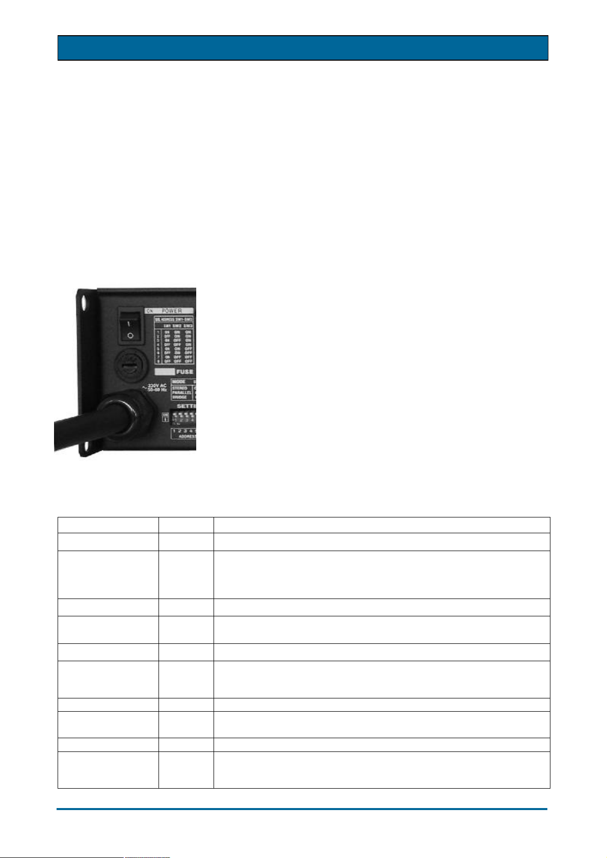
Power Connection
The power amplifier must be connected only with the attached three-wire
safety power cord with protective conductor (non-fused earthed
conductor). This amplifier is made for use with the mains voltage labeled
on the back of the amplifier only.
Check the label on the back panel of the amplifier for the appropriate
voltage. The voltage version of the amplifier is preset and cannot be
changed. Make sure the voltage of your mains outlet is correct. Damage
caused by connecting the amplifier to improper AC voltage voids the
warranty.
The power fuses are located on the back panel of the amplifier and can be
accessed from the outside. Use only the appropriate fuses as labeled.
After properly mounting and connecting the AC cord and the audio
connections, the unit can be switched on. The POWER indication LED
indicates that the amplifier has been turned on.
LED Indicators
The amplifier is equipped with the following LEDs on the front panel:
LED COLOR FUNCTION
ONLINE green Indicates that the unit is connected to an SXL unit or via RS485 network
STANDBY yellow In control mode (SXL, RS-485, RemoteControl Voltage) this LED
indicates that amplifier is in standby mode (power switched off). Manual
power switch overrides this seting. When standby mode is overriden
manually, both STANDBY and POWER leds are ON.
POWER CH1 Green Indicates that amplifier channel 1 is powered up.
CLIP CH1 Red Indicates that the input is overloaded. The LED starts illuminating as
soon as the signal is 0.5 dB under full power.
SIGNAL CH1 Green Indicates, that signal reaches the output stage of the amplifier.
PROTECT CH1 Red This LED will light up as soon a protection circuit has been activated or
if one of the output relays has been activated. When the amplifier is
switched on, this LED illuminated for approximately 1.5 seconds.
POWER CH2 Green Indicates that amplifier channel 2 is powered up.
CLIP CH2 Red Indicates that the input is overloaded. The LED starts illuminating as
soon as the signal is 0.5 dB under full power.
SIGNAL CH2 Green Indicates that signal reaches the output stage of the amplifier.
PROTECT CH2 Red This LED will light up as soon a protection circuit has been activated or
if one of the output relays has been activated. When the amplifier is
switched on, this LED illuminated for approximately 1.5 seconds.
Bittner-Audio

ã
BITTNER Installation & Operations Manual
SYSTEM MONITORING – ALIVE CONTACT
The XR Series amplifiers are equipped with the ‘Alive Contact’. The contact is located on the rear panel of
the amplifier and is a GPI contact closure that indicates the general operation mode of the amplifier. It is
designed as a 3-pole contact closure that can be used in the ‘open’ mode or the ‘closed’ mode:
Alive Contact active: indicates that the amplifier is working in normal conditions
Alive Contact inactive: indicates that the amplifier is not working properly: it is shut
down by the protection circuit, overheated etc. or generally
switched off
This contact closure is the simplest form of remote system monitoring of the amplifier without
establishing a remote control network and provides easy system surveillance at a very
economically level. The ‘Alive Contact’ can also be integrated into a media control network as
a GPI contact closure to trigger eventually needed other control procedures like backup amplifier (spare
amplifier) switching.
SXL DATA PORT
The XR Series amplifiers are equipped with the SXL data port to connect the BITTNER SXL Programmable
Control Interface to the amplifier. To connect the BITTNER amplifiers to the SXL unit all amplifiers must have
a unique address. The address is selected on the DIP switch at the rear panel of the amplifier and can be set
to 1 to 8:
Example: Address 1: ON,ON,ON,ON,ON,ON
Address 2: OFF,ON,ON,ON,ON,ON
After an address change the amplifier must be re-powered to activate the changes!
Up to 16 amplifier channels can be connected to the SXL. The 16 amplifier channels can be combined from
stereo, 4-channel and 8-channel amplifiers.
When the amplifier is connected to the SXL, it is automatically recognised by the SXL unit and the
appropriate Link LED on the SXL front panel indicates ‘ON’. If RS-485 communication (see next chapter) is
not used the same time, permanent communication with the SXL unit is also indicated by fast blinking green
LED (TX) on the amplifier’s rear panel.
The model number and other features of the amplifier can be verified on the SXL front panel LCD in the
group ‘AMP’. The group ‘AMP’ can be browsed using the LEFT and RIGHT keys on the SXL front panel.
For more details please refer to the Operations Manual of the BITTNER SXL.
RS-485 PORTS
The XR Series amplifiers are equipped with two parallel RS485 ports, PORT1 and PORT2 via RJ-45
connectors. Using one of the ports as an input and the second as an output, a RS-485 network with bus
topology can be established easily.
To connect the amplifier to the control computer, the RS-485 address must be set with the DIP switches at
the rear panel of the amplifier. Up to 64 addresses can be selected.
Bittner-Audio

ã
BITTNER Installation & Operations Manual
RS485 is a multi-point communications network with up to 32 drivers and 32 receivers on
a single (2-wire) bus and are able to withstand "data collisions" (bus contention)
problems and bus fault conditions. RS485 extends the common mode range for both
drivers and receivers in the so-called "tri-state" mode.
RS-485 Connector Pinout:
The RS-485 interface on the XR Series amplifiers is a half-duplex transceiver with one
single bus (2-wire) for transmitting and receiving data on the same bus.
RS485 PORT connector (RJ45):
Pin 1 RS485GND
2 NC
3 DATA+
4 DATA5 DATA6 DATA+
7 NC
8 RS485GND
Pin 3 and 6 and pin 4 and 5 carry the same signal.
Note: DATA+ is pulled via 10k resistor to +5V volts and DATA- is pushed to RS485GND
via 10k in idle state.
RS-485 Indicators
Two LED indicators are active while receiving data (red=RX) and transmitting data
(green=TX) over RS485.
RS-485 Address
In the RS-485 control mode the amplifier is identified by its address. Use the DIP
SWITCH ADDRESS 1-6 settings to set the RS-485 node address from 01 to 64:
Example: Address 00: ON,ON,ON,ON,ON,ON
Address 01: OFF,ON,ON,ON,ON,ON
The amplifier must be re-powered before the address change is activated !
For further information to connect the DSP control software, refer to the chapter ‘DSP
Control over RS-485’.
POWER SWITCHING / REMOTE ON/OFF-SWITCHING
There are three options to switch the amplifier on and off.
Option 1 – Manual Switching:
The amplifier can be switched on manually by switch placed on back panel. When
amplifier is switched on manually, it can't be switched on/off remotely. Manual switch
overrides remote switch control. To switch the amplifier remotely, the manual switch must
be in OFF position.
Option 2 – Remote Switching with 12VDC-Control Voltage:
The PHOENIX terminal block is used for remote switching with a control voltage (12VDC). Terminal 1 and 2
are used as the control voltage input. Supplying the control voltage to these terminals will switch the amplifier
ON. After a delay of one second internally the terminals 4 and 5 of the PHOENIX terminal block will be fed
Bittner-Audio
ã
BITTNER Installation & Operations Manual
PHOENIX Connector
with the control voltage. These terminals are intended to be connected to terminals 1 and 2 of the next
amplifier for sequential power switching. Up to 10 units can be daisy-chained this way for sequential power
switching.
The control voltage must be supplied until the last amplifier in the daisy-chain setup is switched on. If no RS485 control is used, the control voltage can be then removed. When RS-485 is used, 12 VDC must stay
connected to supply amplifiers also in standby mode. The amplifiers PowerOn/Standby mode is then
controled over RS-485 - see section ‘DSP Control over RS-485’.
By supplying the inverted DC control voltage to terminal 1 and 2, the amplifier will be switched off (turn +/- to
-/+). As for the powering-up procedure, the control voltage is internally fed to the terminals 4 and 5 for
supplying the control voltage to the next daisy-chained amplifier. For the switching-off sequence, no delay is
engaged and all amplifiers are switched of at the same moment.
The control voltage/amperage is 12VDC and the necessary current is 80mA during switching on the amplifier
or in Standby mode. The needed current is zero as soon as the amplifier is supplied by its own power
supply.
Remote Switching PHOENIX Connector:
1 – Amplifier Switching POSITIVE terminal
2 – Amplifier Switching NEGATIVE terminal
3 – Control Voltage supply for sequential switching POSITIVE terminal
4 – Control Voltage supply for sequential switching NEGATIVE terminal
Option 3 – Remote Switching from control unit
When connected online to controllers BITTNER SXL or via RS-485 network to PC with the appropriate DSP
control software, the amplifier can be switched on and put to Standby mode by any of the controllers.
AUDIO CONNECTIONS
Always turn off the amplifier before making any connections. As an additional precaution by switching the
amplifier on for the first time, turn the audio attenuators down during powering up.
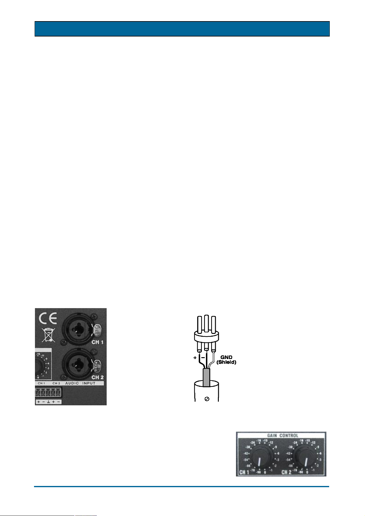
Audio Input Connectors
The XR Series amplifiers are equipped with two XLR input connectors and parallel PHOENIX connectors,
both on the rear panel of the amplifier. The audio inputs of the series XR amplifiers are electronically
balanced. The XLR connector is a combined XLR / TRS jack connector.
Standard
XLR Connector
Pinout:
1 = Ground, Shield
2 = Signal positive
3 = Signal negative
Pinout:
Pin 1 = Signal + CH 1
Pin 2 =•Signal – CH 1
Pin 3 =•Ground CH 1 + CH 2
Pin 4 =•Signal + CH 2
Pin 5 =•Signal – CH 2
Input Gain Controls – Digital Potentiometers
The XR Series amplifiers are equipped with wear-free digital rotary level
controls with rotary steps for each channel at the rear panel of the
amplifier.
If the unit is connected online to the BITTNER SXL control unit or to
another control device (computer) via the RS-485 port, the gain can be
controlled from the connected control unit. Any changes in the gain
settings from the control device will override the settings on the local
Bittner-Audio

ã
BITTNER Installation & Operations Manual
digital potentiometers. Only changing the potentiometer position will override the last settings from the
control unit. In short, last change always replaces previous setting no matter whether it came from control
unit or digital potentiometer.
Attention: the last gain setting is always stored in the amplifier’s memory. Turning the amplifier on, the stored
gain setting is used. The setting of digital potentiometer is used after startup only when the potentiometer is
at -90dB position. This case amplifier starts with -90dB gain.
Balanced and unbalanced Inputs, Levels
The amplifier can accept unbalanced or balanced lines. For optimum performance and with longer cable
runs, use balanced lines whenever possible. The driving device should be equipped with a balanced output.
With short cables inside one rack the issue is not that critical.
A balanced connection provides excellent noise immunity from interference and ground loops. A balanced
audio connection is accomplished by using a differential pair of signals, isolating them from ground. While
these connections provide great noise immunity, care must be taken when connecting balanced and
unbalanced equipment together.
Grounding
The chassis ground of the amplifier is connected with the ground of the AC power cord (the non-fused
earthed protective conductor). As soon as several devices are connected with each other in a signal chain,
a ground loop is created. Ground loops are caused when current flows from the analog ground plane of one
piece of equipment to the ground plane of another. A compensating current travels between the different
devices on the shields of the audio cables. Make sure all audio connections are appropriately grounded and
shielded to avoid hum-problems. NEVER isolate the ground of the AC power cord (the non-fused earthed
protective conductor). This is a violation of the law and dangerous!
Decibel Explanation
A decibel is a logarithmic scale commonly used to express differences in signal levels. It is useful in audio
because it can express a wide dynamic range with relatively small numbers (or a small movement on a
meter), and it more closely matches how we perceive sound.
The measurement quoted in dB describes the ratio between the quantity of two levels, the level being
measured and a reference. The absolute quantity of the signal is not relevant. This means that decibels are
always comparing one quantity to another. For example, when we measure gain in dB, we are comparing
the output level to the input level.
To describe an absolute value, the reference point must be known. There are different reference points
defined.
dBV represents the level compared to 1 Volt RMS: 0dBV = 1V with no reference to impedance.
dBu represents the level compared to 0,775 Volt RMS on an unloaded, open circuit.
dBm represents the power level compared to 1 mWatt. This is a level compared to 0,775 Volt RMS across a
600 Ohm load impedance.
1dBV equals +2.2dBu, +4dBu equals 1.23 Volt RMS, the reference level of -10dBV is the equivalent to a
level of -7.8dBu.
Headroom is a measure (usually in dB) of how much higher the peaks of a signal can be compared to the
nominal level without clipping. That is, it compares the peak level (in volts RMS) to the nominal level (in volts
RMS). The difference between the two (in dB) is the headroom.
Loudspeaker Output Connectors
The impedance of the connected loudspeaker line could be between 2 Ohms and 16 Ohms. The minimal
connected loudspeaker impedance is 2 Ohms. In the
BRIDGE operation mode the minimal connected
impedance is 4 Ohms.
Output wiring
Use heavy gauge wire for speaker connections. The
greater the distance between the amplifier and the
speakers, the larger the diameter the wire should be.
Bittner-Audio

ã
BITTNER Installation & Operations Manual
This will minimize power losses across the wire and improve damping of the speaker. Wire thickness
specifications (gauges) get larger as the wire gets thinner. So a 14-gauge wire is thicker than 18-gauge wire.
Speaker cables can be connected to the PHOENIX connectors or to the 4 pin NEUTRIK SPEAKON
connectors. The PHOENIX connectors are preferable designed for fixed installations.
Speakon Connector Pinout:
1 + positive terminal
1 − negative terminal
2 + (not connected)
2 − (not connected)
It is possible to use both connections parallel at the same time. Please pay attention that the “+” pole of the
PHOENIX connectors corresponds to the „1+” pin of the SPEAKON connector of the corresponding channel.
The impedance of the connected loudspeaker line could be between 2 Ohms and 16 Ohms. The minimal
loudspeaker impedance is 2 Ohms. In the operation mode BRIDGE the minimal impedance is 4 Ohms.
OPERATION MODES
On the rear of the amplifier three different operation modes can be selected on the DIP-Switch panel:
STEREO, PARALLEL and BRIDGED MODE.
The amplifier must be re-powered before the mode change is activated !
Stereo Operation
For stereo operation, turn the amplifier off and set the mode select switches to the STEREO position. In this
mode, both channels operate independently of each other, with their input attenuators controlling their
respective levels. Thus, an input signal at Channel 1 produces an amplified signal at the output of Channel 1,
while an input signal at Channel 2 produces an amplified signal at the output of Channel 2.
The minimum load impedance for stereo operation is 2 Ohms per channel.
The loudspeaker could be connected to the SPEAKON connector and / or to the PHOENIX connectors at the
same time. A mixed connection is also possible.
Parallel Operation
For parallel operation, turn the amplifier off and set the mode select switches on the PARALLEL position.
Both amplifiers are then driven by the signal of channel 1. Output connections are the same as for the stereo
operation.
Only the input of channel 1 is active, the input of channel 2 is out of circuit. Input attenuator 1 controls both
channel levels
The loudspeaker could be connected to the SPEAKON connector and / or to the screw terminals. A mixed
connection is also possible.
Bridged Operation (Mono)
Both amplifier channels can be bridged to create a powerful single-channel mono amplifier. Use extreme
caution when operating in bridged mode. To bridge the amplifier, turn the amplifier off and set the rear mode
select switches to the BRIDGED position.
Only the input of channel 1 is active, channel 2 is out of circuit. Only attenuator 1 remains active and controls
both channels gain. Connect the speakers across the “+” terminals of both PHOENIX connectors. The
‘positive’ pole of the loudspeaker should be connected to the “+” terminal of channel 1, the ‘negative’ pole to
the “+” terminal of channel 2.
The recommended load impedance for the bridged operation is 8 Ohms. Minimal impedance for the bridged
operation is 4 Ohms.
Bittner-Audio

ã
BITTNER Installation & Operations Manual
DSP PROCESSOR
The Series XR amplifiers are equipped with an internal DSP processor. With the internal processor extended
functionality is available:
- Level Control
- Input routing of the two amplifier channels
- 10-Band Equalizer
- Dynamics (Limiter/Compressor/Gate)
- Delay
- Cross-Over
- Up to 100 stored presets
Two way of controlling the internal DSP are available:
1. the control interface BITTNER SXL, connected to the amplifier via control network
2. the DSP software installed on a computer, connected via RS-485 to the amplifier
1.1 DSP Control Interface SXL with SXL Web interface:
(See also chapter ‘SXL Data Port’.) The DSP can be controlled with the Web Interface of the BITTNER SXL
Control Interface. The amplifier must be connected to the SXL unit by ribbon cable and as the next step the
SXL unit must be connected to the controlling PC over the Ethernet control network to establish access to
the built-in-sxl web server.
When the SXL unit is addressed via Web browser, the DSP control page of the Web Interface is available
and all features of the DSP are accessible via the web interface (see image below).
The available SXL presets (settings of all amplifiers, 16 channels and SXL) are called Configurations (Cfg)
and can be saved and recalled from the SXL’s internal memory.
A signal generator is also available within the DSP functionality and can be used as pilot tone generator
(loudspeaker line test) or as test tone generator for measurements etc.
Note: Controls that are not used with the specified amplifier model are disabled i.e. not used and not available.
screen shot of the DSP control over the SXL web interface
Note: To obtain access to the SXL web interface, the user must first log-in. Default name/password is:
Bittner-Audio

ã
BITTNER Installation & Operations Manual
Username: sxl
Password: 11111
Please refer for more detailed information to the SXL Manual.
2. DSP Control over RS-485:
(See also chapter ‘RS-485 Ports’.) The DSP can be controlled also via the RS-485 port on the rear panel of
the amplifier. For this control mode the appropriate software must be installed on a computer. The computer
must be connected to the RS-485 port. The RS-485 interface was chosen to be able to control the unit
remotely over longer distances. If the unit should be controlled locally, any standard Interface from USB or
RS-232 to RS-485 can be used to get the computer connected to the RS-485 port of the amplifier.
As soon as the amplifier is connected to the control computer, the unit can be manually connected (menu
‘Devices’) or scanned automatically.
After connecting to the amplifier’s DSP, the shown sub windows can be opened and positioned freely on the
main window. With the preset functionality the current settings can be stored. Up to 100 DSP presets can be
stored and recalled.
Note: Presets can't be stored / recalled while amplifier is in Standby mode.
The DSP control software for PC (WindowsTM) is available from BITTNER Audio.
screen shot of the DSP control with PC software, over the RS-485 interface
Bittner-Audio

ã
BITTNER Installation & Operations Manual
CHANNEL MEASUREMENT
The Series XR amplifiers monitor input/output values of every switched-on channel. All of the values are
available via SXL control unit and the vital ones also via RS-485 interface.
XR amplifier monitors:
- Input level
- Output peak voltage
- Load impedance (output signal at least 30 dB under nominal power must be present)
- Output peak current
- Output power
- Headroom
- Heatsink temperature
Detected are Protect, Clip, Output Open and Output Short conditions.
When SXL control unit is connected, Open/Short threshold in ohms can be defined by user.
Via RS-485 interface vital monitors/detectors are available - protect, temperature, load impedance.
Bittner-Audio

ã
BITTNER Installation & Operations Manual
WARRANTY TERMS & CONDITIONS
Bittner-Audio (the manufacturer) warrants this product to be free from defects in materials and workmanship.
Should any part of this equipment be defective, the Manufacturer agrees to repair or replace any defective
part free of charge (except transportation charges) for a period of three years from the date of the original
purchase.
Warranty service is effective and available to the original purchaser only.
To obtain service under this warranty, the product must, on discovery of the defect, be properly packed and
shipped to the nearest Bittner-Audio dealer. The party requesting service must provide proof of original
ownership and date of purchase of the product.
If the warranty is valid, Bittner-Audio will, without charge for parts or labor, either repair or replace the
defective parts. Without a valid warranty, the entire cost of the repair is the responsibility of the product’s
owner.
The warranty does not cover defects or repairs needed as a result of:
1. Damage caused by abuse, accident, or negligence.
2. Damage caused by any tampering, alteration, or modification of the product or its components.
3. Damage caused by failure to maintain and operate the product in strict accordance to the written
instruction of this operating manual.
4. Damage caused by repairs or attempted repairs by unauthorized persons.
5. Damage caused by fire, water and other natural events.
6. Damage caused by operation on improper voltages.
BTTNER-Audio
Bittner-Audio

ã
BITTNER Installation & Operations Manual
TECHNICAL SPECIFICATIONS
Model
Number of Channels
Class
Power at 8+8 Ohm (1kHz, 0.1%THD
Power at 4+4 Ohm (1kHz, 0.1%THD)
Power at 2+2 Ohm (1kHz, 0.1%THD)
Power Bridge Mode 8 Ohm (1kHz, 1%THD)
Power Bridge Mode 4 Ohm (1kHz, 1%THD)
Frequency Response Full Power
20Hz - 20kHz (dB)
THD + N (%)
Inputs
Input Impedance
Input Sensitivity
Input Clipping
Minimal Load Impedance
Minimal Load Impedance in Bridge Mode
Channel Separation
Signal to Noise Ratio (20Hz – 20kHz)
Weight
Installation Height
Installation Depth
XR 1500 XR 2000 XR 2500 XR4000
2 2 2 2
H H H H
2 x 430 W 2 x 620 W 2 x 810 W 2 x 1240 W
2 x 750 W 2 x 1000 W 2 x 1250 W 2 x 2070 W
2 x 1050 W 2 x 1400 W 2 x 1600 W 2 x 2800 W
1300 W 1850 W 2200 W 3880 W
1800 W 2400 W 2900 W 4000 W
0 / - 0.3 dB 0 / - 0.3 dB 0 / - 0.3 dB 0 / - 0.3 dB
0.02 0.02 0.02 0.02
electronically
balanced
12 kOhm 12 kOhm 12 kOhm 12 kOhm
+ 6 dBu + 6 dBu + 6 dBu + 6 dBu
+ 22 dBu + 22 dBu + 22 dBu + 22 dBu
2 Ohm 2 Ohm 2 Ohm 2 Ohm
4 Ohm 4 Ohm 4 Ohm 4 Ohm
> 85 dB > 85 dB > 85 dB > 85 dB
106 dB 107 dB 107 dB 110 dB
24 kg 24 kg 25 kg 25 kg
2 RU 2 RU 2 RU 2 RU
454 mm 454 mm 454 mm 454 mm
electronically
balanced
electronically
balanced
electronically
balanced
Bittner-Audio
 Loading...