

Page 1

User Manual
User ManualUser Manual
User Manual
Page 2

USER MANUAL
Table of contents
INTRODUCTION...................................................................................................................................................5
THE BITSTREAM 3X............................................................................................................................................5
TERMINOLOGY....................................................................................................................................................6
INSTALLATION OF THE DRIVERS AND SOFTWARE................................................................................7
GETTING STARTED WITH THE BITSTREAM 3X........................................................................................7
CONNECTION TO A COMPUTER..........................................................................................................................................7
CONNECTION WITHOUT A COMPUTER.................................................................................................................................8
DESCRIPTION OF THE FRONT AND REAR PANELS OF THE BITSTREAM 3X..................................................................................9
FRONT: TYPE OF CONTROLS AND NUMBERING.....................................................................................................................9
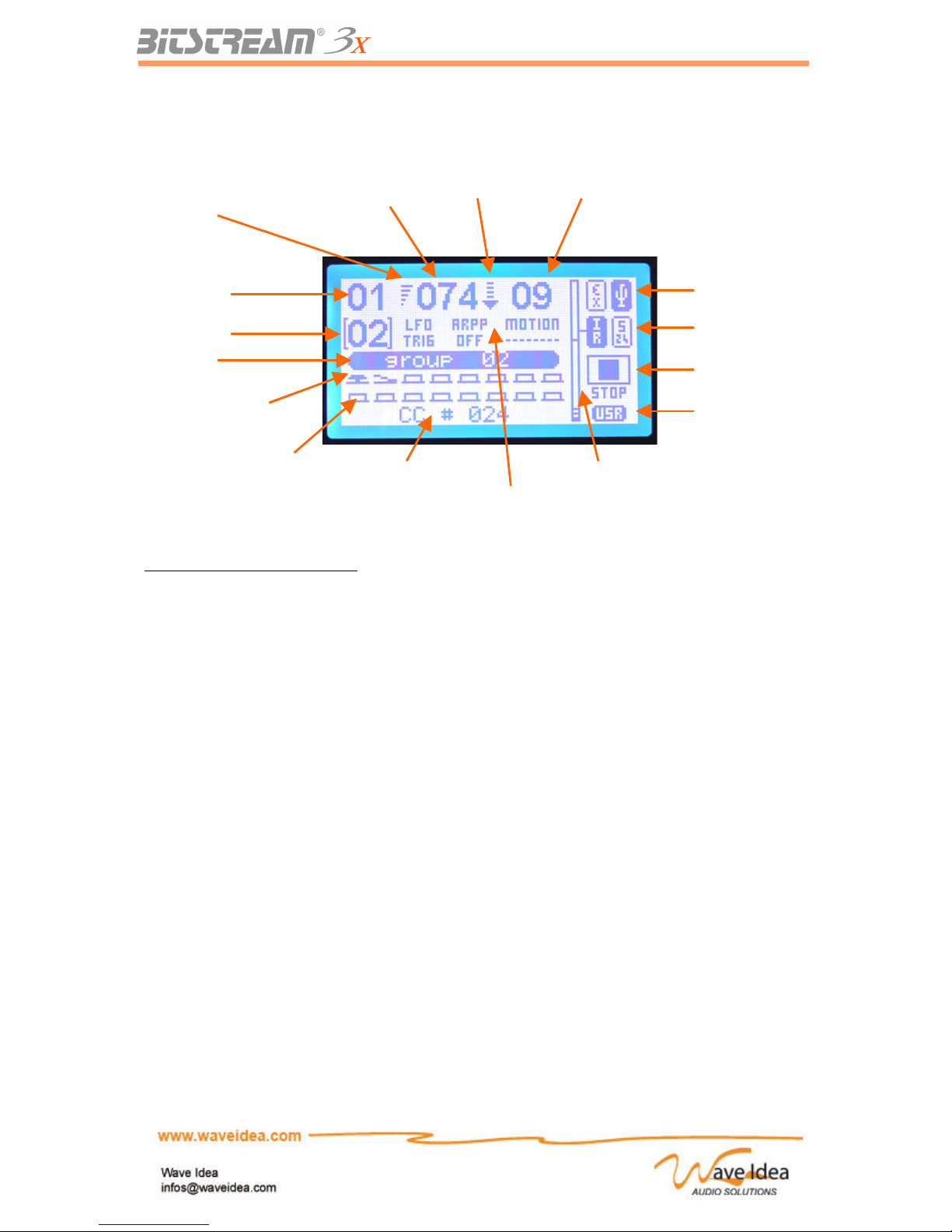
DESCRIPTION OF THE LCD SCREEN...............................................................................................................................11
The LCD Screen in « Normal Mode »................................................................................................................11
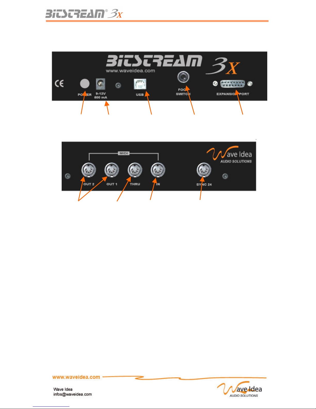
REAR PANEL: DESCRIPTION OF THE INPUTS AND OUTPUTS....................................................................................................12
THE EXPANSION PORT....................................................................................................................................12
OPERATING MODES OF THE BITSTREAM 3X..........................................................................................13
DIFFERENCES BETWEEN STANDARD MODE AND USER MODE................................................................................................13
STANDARD MODE........................................................................................................................................................13
PROPELLERHEADS REASON MODE..................................................................................................................................13
USER MODE...............................................................................................................................................................13
CONFIGURATION AND USAGE OF THE BITSTREAM 3X.......................................................................14
THE INFRARED CONTROLLER ........................................................................................................................................14
THE CROSS-FADER......................................................................................................................................................15
THE JOYSTICK.............................................................................................................................................................16
SELECTION OF THE «CURRENT FUNCTION»......................................................................................................................16
Role of the up-down buttons and the encoder....................................................................................................16
SELECTION OF THE GROUP.............................................................................................................................................17
SELECTION OF THE MIDI CHANNEL................................................................................................................................17
SELECTION OF THE SCENE MEMORIES...............................................................................................................................18
ANALOG BEHAVIOUR....................................................................................................................................................18
DIGITAL BEHAVIOUR....................................................................................................................................................19
CURVE MODELS..........................................................................................................................................................20
MIDI AND USB INPUTS..............................................................................................................................................21
MIDI AND USB OUTPUTS..........................................................................................................................................22
COMPLETE SCHEMATIC OF THE MIDI AND USB ROUTING.................................................................................................1
CHAIN OF CONTROLS....................................................................................................................................................24
Example of Usage...............................................................................................................................................24
ASSIGNING MIDI EVENTS TO THE CONTROLS OF THE BITSTREAM 3X.........................................24
STANDARD VERSUS USER MODE ...................................................................................................................................24
USING THE CONFIGURATION SOFTWARE..........................................................................................................................24
USING THE « ASSIGN » MENUS......................................................................................................................................25
CONFIGURATION OF THE CONTROLS OF THE BITSTREAM 3X................................................................................................26
MIDI events associated with the Standard mode................................................................................................26
MIDI events associated with User mode............................................................................................................26
The common parameters in Standard and User modes......................................................................................27
Selection of MIDI and USB Outputs................................................................................................................................27
“Auto-send”......................................................................................................................................................................27
Exclusion of a control of scene memories......................................................................................................................27
Digital Behaviour..............................................................................................................................................................28
The parameters dedicated to Standard mode ....................................................................................................28
Number of the CC or Note...............................................................................................................................................28
The parameters dedicated to User mode............................................................................................................28
Min & Max values.............................................................................................................................................................28
Rev 1.1 - Page 2
Page 3

USER MANUAL
Selection of the MIDI Delay.............................................................................................................................................29
Curve Models...................................................................................................................................................................29
Checksum Management for exclusive systems..............................................................................................................29
Chaining the Controls......................................................................................................................................................30
Alphanumeric LCD Chain................................................................................................................................................30
MIDI Channel...................................................................................................................................................................31
MIDI String.......................................................................................................................................................................31
Control value positions 1 & 2...........................................................................................................................................32
Split control value............................................................................................................................................................32
THE TRANSPORT BAR ....................................................................................................................................33
CONFIGURATION..........................................................................................................................................................33
SYNCHRONIZATION OF THE BITSTREAM 3X......................................................................................................................33
USAGE OF STANDARD BUTTONS......................................................................................................................................34
SCENE MEMORIES............................................................................................................................................35
GOAL.........................................................................................................................................................................35
RESTITUTION OF SCENES................................................................................................................................................35
SAVING THE SCENES.....................................................................................................................................................36
AUTOMATIONS..................................................................................................................................................36
KNOBS AND BUTTONS ASSOCIATED WITH THE AUTOMATIONS................................................................................................36
Functions of the controls associated with automations......................................................................................37
WAVEFORMS GENERATOR: LOW FREQUENCY OSCILLATOR................................................................................................37
Selection of the Waveform..................................................................................................................................37
Output Amplitude ...............................................................................................................................................37
Adjustment of the frequency and synchronization..............................................................................................38
Synchronization of the LFO from the internal or external MIDI clock..............................................................38
Adjustment of the offset value.............................................................................................................................39
ARPPEGGIATOR............................................................................................................................................................41
Goal....................................................................................................................................................................41
Rhythm................................................................................................................................................................41
Accent..................................................................................................................................................................41
Gate.....................................................................................................................................................................41
Melody.................................................................................................................................................................42
Transpose............................................................................................................................................................42
Range..................................................................................................................................................................42
Resolution...........................................................................................................................................................42
Direction.............................................................................................................................................................42
Modes and synchronization................................................................................................................................43
Velocity ..............................................................................................................................................................44
Swing...................................................................................................................................................................44
Offset...................................................................................................................................................................44
Channel...............................................................................................................................................................44
MOTION SAMPLER.......................................................................................................................................................47
Goal....................................................................................................................................................................47
Recording a Sequence.........................................................................................................................................48
Restitution of a sequence....................................................................................................................................49
SYNC-24 OUTPUT...............................................................................................................................................51
GOAL.........................................................................................................................................................................51
ELECTRICAL SIGNALS GENERATED.................................................................................................................................52
NAVIGATION OF THE MENUS.......................................................................................................................52
PRINCIPLES OF NAVIGATION...........................................................................................................................................52
HIERARCHY OF THE MENUS (SUMMARY)........................................................................................................................54
OTHER USEFUL FUNCTIONS.........................................................................................................................58
SHIFT KEY...............................................................................................................................................................58
Blocking MIDI Data...........................................................................................................................................58
Blocking Bitstream 3X MIDI Channel insertion.................................................................................................58
Access to supplementary digital controls...........................................................................................................58
Increasing the range of value changes...............................................................................................................58
Rev 1.1 - Page 3
Page 4

USER MANUAL
Access to multiplexed parameters.......................................................................................................................58
INITIALISATION OF THE BITSTREAM 3X...........................................................................................................................59
REGULATING THE CONTRAST..........................................................................................................................................59
UPDATING THE FIRMWARE.............................................................................................................................................60
REVERSAL OF THE VIDEO MODE......................................................................................................................................61
USAGE EXAMPLES OF THE BITSTREAM 3X.............................................................................................62
USAGE WITH A SYNTHESIZER SOFTWARE...........................................................................................................................62
Propellerheads Reason.......................................................................................................................................62
Ableton Live........................................................................................................................................................64
DEFINITION OF THE EXCLUSIVE SYSTEMS OF THE BITSTREAM 3X..............................................66
GENERAL FORMAT OF EXCLUSIVE SYSTEMS......................................................................................................................66
LIST OF THE GLOBAL PARAMETERS ACCESSIBLE VIA SYSEXS................................................................................................68
Example of communication.................................................................................................................................70
DEFINITION OF MIDI DATA ASSIGN ACCESSIBLE VIA SYSEXS..............................................................................................70
DEFINITION OF THE LCD ASSIGN DATA ACCESSIBLE VIA SYSEXS.........................................................................................72
MIDI OVERVIEW................................................................................................................................................73
INTRODUCTION............................................................................................................................................................73
NUMBERS AND CONVENTIONS.........................................................................................................................................73
MIDI HARDWARE INTERFACE........................................................................................................................................73
MIDI DATA FORMAT....................................................................................................................................................73
CHANNEL MESSAGES.....................................................................................................................................................74
MODE........................................................................................................................................................................74
VOICE........................................................................................................................................................................74
SYSTEM MESSAGES.......................................................................................................................................................74
COMMON....................................................................................................................................................................74
REAL-TIME.................................................................................................................................................................74
EXCLUSIVE.................................................................................................................................................................75
ADDITIONAL STATUS NOTES...........................................................................................................................................75
RUNNING STATUS.........................................................................................................................................................75
UNDEFINED AND UNIMPLEMENTED STATUS.......................................................................................................................75
Table 1: MIDI byte value summary....................................................................................................................76
TECHNICAL CHARACTERISTICS ................................................................................................................78
Rev 1.1 - Page 4
Page 5
USER MANUAL
Introduction
Congratulations, you have just purchased a MIDI Controller from Wave Idea: the Bitstream 3X.
The Bitstream 3X is a part of the latest generation of high performance MIDI controllers dedicated to
use in home studios or on stage.
Featuring all the required inputs and outputs for the applications below, the Bitstream 3X was
developed with the musician in mind to give him all the necessary controls to get maximum usage out
of the latest software or MIDI compatible material.
We made this user manual as complete as possible, and if you need more information check the
website of Wave Idea: www.waveidea.com, or contact the support team at: [email protected]
The Bitstream 3X
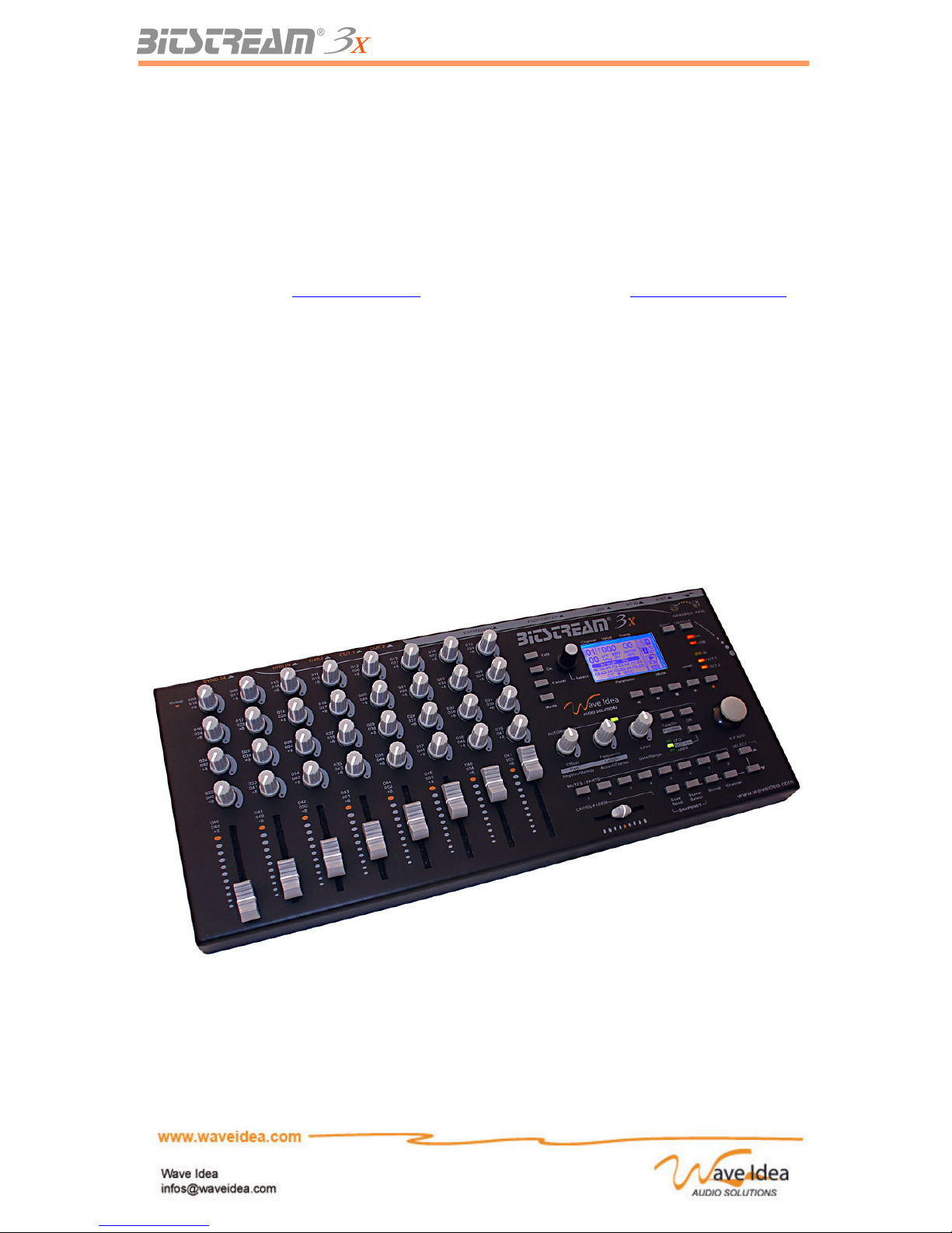
The Bitstream 3X is an entirely advanced programmable universal MIDI controller, designed for both
amateur and experienced users. It offers a large number of controls of all types (sliders, buttons,
joystick, infrared controller …) allowing maximum usage of the machine or software to which it is
connected.
Besides a MIDI controller, the Bitstream 3X gives you many necessary automations for on stage use
(arppeggiator, LFO, motion sampler…); allowing to automate the release of MIDI notes and events.
Rev 1.1 - Page 5
Page 6

USER MANUAL
Terminology
The terms below are widely used throughout this manual, and we explain them here to make sure their
exact meanings are understood in order to make this manual clearer.
Analog Controls of which values can vary from 0 to 127 (as opposed to digital controls)
Arppeggiator Feature allowing the generation of MIDI notes depending on user parameters input
Assignable Controls of the Bitstream 3X which can generate MIDI events
Assignation MIDI configuration of a Bitstream 3X control
Control
change CC
Standard MIDI event recognized by any MIDI device or software
Control Any knob, slider, button
Digital Two states of control (on/off), as opposed to analog control
Download Action to send a new assign configuration to the Bitstream 3X
Driver Program that allows to a computer to recognize the Bitstream 3X
Firmware Embedded software of the Bitstream 3X, also called OS
Footswitch Digital input allowing the connection of an external pedal
Global Bitstream 3X parameter which doesn’t correspond to an assignation
Group Set of configured controls of the Bitstream 3X
Hook Controls behaviour that avoids ‘jumps’ of their values when changing from one group to
another
Jump Control behaviour that reflects the physical value of the control
LCD Display of the Bitstream 3X
LFO Low Frequency Oscillator
MMC MIDI Machine Control : transport function MIDI events, allowing synchronization
Note On/Off MIDI Message controlling musical notes
NVM « Non volatile memory » : internal memory of the Bitstream 3X, allowing you to save
your configuration even without it being powered
Push Digital control behaviour of the Bitstream 3X (as opposed to ‘toggle’)
Scene Physical position of all the Bitstream 3X controls. Can be saved at any time.
Slider Vertical potentiometer, 8 of them are present on the Bitstream 3X
Sync-24 Synchronisation protocol of vintage (pre-MIDI) instruments like TB-303…
Sysex System Exclusive : device/manufacturer specific MIDI event
Toggle Behaviour of a digital control as opposed to ‘push’
Upload Action to read from the Bitstream 3X a configuration assigned
User Parameter defined by the user
Rev 1.1 - Page 6
Page 7

USER MANUAL
Installation of the drivers and software
The Bitstream 3X is a « plug and play » device, fully compliant with the MIDI over USB specification.
This means that it doesn’t require a particular driver on any operating system OS’s compatible with this
specification, which is the case for almost any OS including Windows XP, MacOS X, and Linux.
Just connect your Bitstream 3X USB cable to a PC or a Mac, and it’s ready to use!
Note 1: The first connection of the Bitstream 3X to the USB port will install automatically the generic
drivers. After the first connection, the Bitstream 3X will be immediately recognized.
Once the Bitstream 3X is recognized by the computer to which it is connected, the display screen will
indicate the connection by the USB bitmap on the top right.
Once the Bitstream 3X is recognized, the supplementary MIDI peripherals will be listed. These
correspond to the Bitstream 3X like this:
Peripheral listed Name associated by default C orresponding to the Bitstream 3X
USB MIDI IN 1 USB audio device USB MIDI OUT 1
USB MIDI IN 2 USB audio device [2] USB MIDI OUT 2
USB MIDI OUT USB audio device USB MIDI IN
Note 2: Windows 98 and 2000 do not support MIDI-USB standards, if the Bitstream 3X is going to be
used with one of these systems, contact the support team at Wave Idea.
Note 3: Windows should be installed with the latest Windows update so that the communication MIDI –
USB functions perfectly. (Example Windows Xp service pack 2)
Note 4: A special Windows Xp driver is available from the Wave Idea website, it allows to change the
generic devices names listed above ( USB audio device) to a more convenient name “Wave Idea
Bitstream 3X”. This driver is optional and not required for the proper operation under Windows Xp.
Getting started with the Bitstream 3X
Connection to a computer
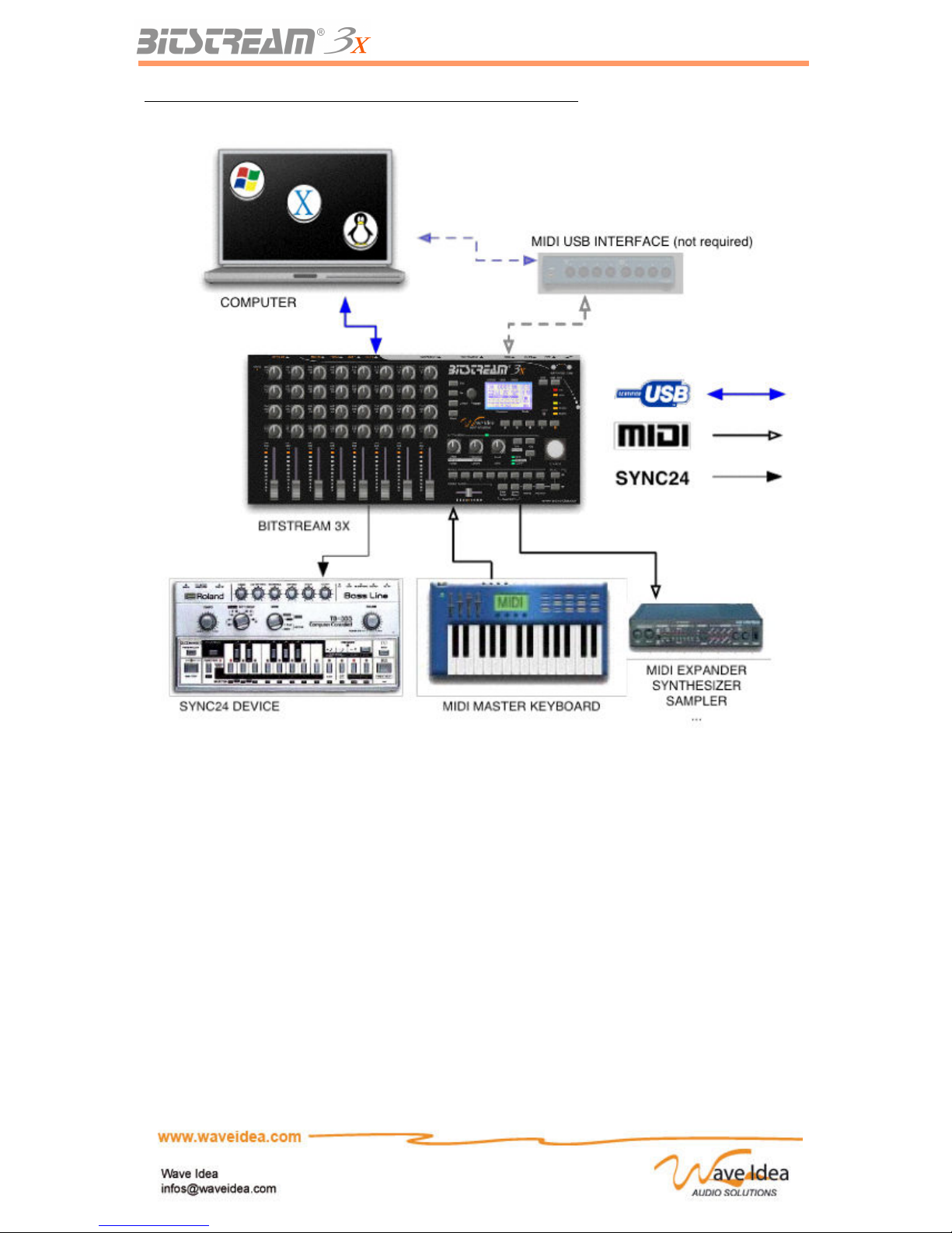
Connecting the Bitstream 3X to a computer can simply done via the USB port. This port is capable of
transferring MIDI data to the Bitstream 3X, as well as powering the controller without requiring the
transformer that came with the machine.
The Bitstream 3X can also be connected to a computer via standard MIDI ports, if the computer is
equipped with MIDI ports, the Bitstream should then be connected to these, being sure to connect the
input « MIDI In » on the Bitstream to the « MIDI Out » of the computer and vice-versa as with any other
MIDI gear.
In this case, the user can chose to connect the USB port to add supplementary MIDI inputs and
outputs, and to power the Bitstream via the same USB port.
The user can also decide to not connect the USB port, and in this case, the usage of the external
transformer is required.
Note 1: The connection of the USB port powers the Bitstream 3X, in this case the connection of the
external electricity source is not required.
Note 2: The external transformer could be connected at the same time as the USB port as the
Bitstream 3X has an intelligent power supply system which allows it to accept the two sources at the
same time.
Rev 1.1 - Page 7
Page 8
USER MANUAL
Example of the complete connection between MIDI and a computer
Connection without a computer
The Bitstream 3X can be connected to all musical instruments which are MIDI via the standard MIDI
ports, if the instrument is equipped with MIDI ports with DIN-5 connectors, the Bitstream should be
connected to these, taking care to connect the MIDI Input of the Bitstream to the MIDI Output of the
instrument, and vice versa.
Connecting without a computer requires the usage of the external transformer that came with the
machine.
Note 1: The usage of an external transformer other than the one delivered with the machine is not
recommended. However, a transformer with the same characteristics could be used:
- Output Voltage 9V DC
- Curent of 400 mA minimum
- Any Polarity (The Bitstream adapts itself to the polarity of the external transformer)
Rev 1.1 - Page 8
Page 9
USER MANUAL
Description of the front and rear panels of the Bitstream 3X
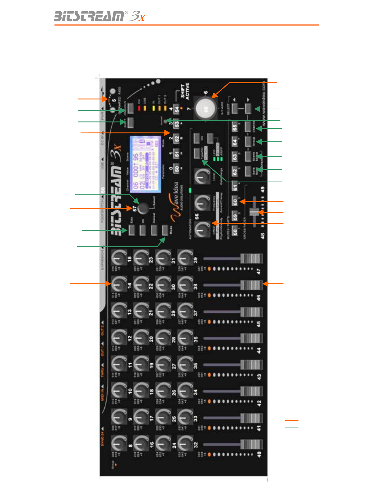
Front: Type of controls and numbering
Rev 1.1 - Page 9
35 rotary
potentiometers
8 linear sliders
1 LFO
8 Buttons
1 Infrared
Controler
5 Transport
Buttons
+
5 assignable
buttons
(SHIFT
activated)
1 Button
encoder
1 Cross-Fader
Assignable
Hold Key
Shift Key
Edit Ok Cancel
Mode Key
Selection
Encoder
Contrast control
MIDI channels
Groups
Selection of scenes
Access to scenes
Up-Down Selection
keys
Access to
Automations
Parameters
1 Joytsick
- 2 axes
- 1 button
Page 10
USER MANUAL
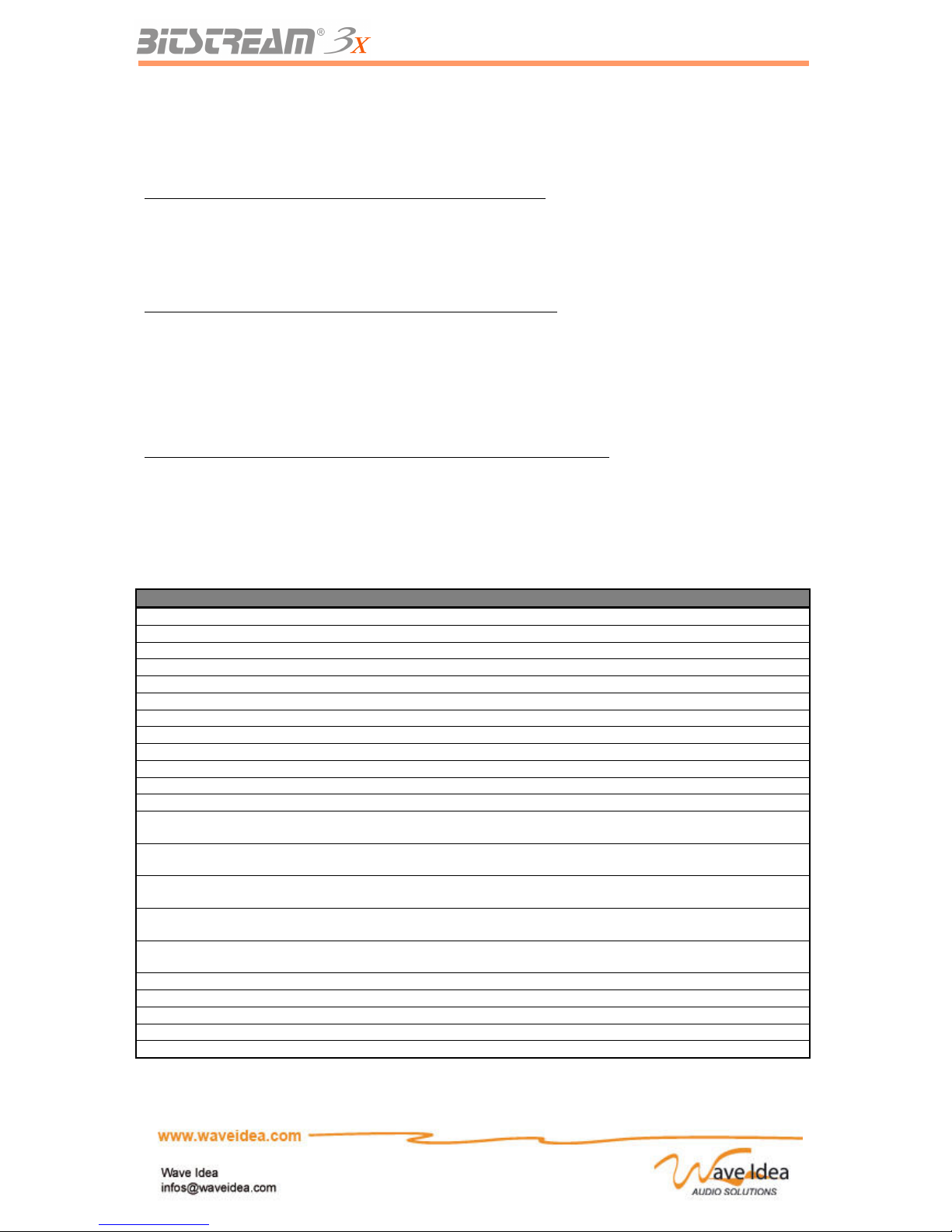
The white numbers on the machine in the preceding image are the numbers associated to each
control. These are the numbers of the CC or Note associated to the control in « normal mode » of the
Bitstream 3X, and this for the group « 0 ».
Each incrementation of group number increases by 8 the CC/Note generated by the Bitstream 3X in
standard mode.
Example 1: CCs generated by the 2 nd slider in Standard Mode:
Group 0: CC or Note # 41
Group 1: CC or Note # 49
Group 2: CC or Note # 57
…
Example 2: CCs generated by the first button in Standard mode:
Group 0: CC or Note # 58
Group 1: CC or Note # 66
Group 2: CC or Note # 74
…
Note: the numbers of the CC’s generated are « modulo 128 », as defined by the MIDI standard
Summary of the controls numbers assigned to the Bitstream 3X controls
The following table illustrates the huge number of controls available on the Bitstream 3X. Each of these
controls is able to generate MIDI events in Standard mode (CC or Note numbers listed here,
depending on selected group), as well as in User mode.
All the controls mentioned with « depends on group number » are able to generate 21 different MIDI
events corresponding to the 21 Bitstream 3X groups.
Number Description Note
0
Record button Shift function not active
1
Play button Shift function not active
2
Backward button Shift function not active
3
Stop button Shift function not active
4
Forward button Shift function not active
5
Infrared controller Depends on group number
6
Joystick Axis X Depends on group number
7
Joystick Axis Y Depends on group number
8-39
32 Rotary potentiometers Depends on group number
40-47
8 linear sliders Depends on group number
48
Cross-fader left Depends on group number
49
Cross-fader right Depends on group number
50
Backward button Shift function active
Depends on group number
51
Forward button Shift function active
Depends on group number
52
Stop button Shift function active
Depends on group number
53
Play button Shift function active
Depends on group number
54
Record button Shift function active
Depends on group number
55
Joystick button Depends on group number
56
Footswitch input Depends on group number
57
Encoder button Depends on group number
58-65
Buttons 1 to 8 Depends on group number
66
LFO Depends on group number
Rev 1.1 - Page 10
Page 11
USER MANUAL
Description of the LCD Screen
The LCD Screen in « Normal Mode »
Description of the different zones
MIDI Channel Indication of the current MIDI channel (1-16)
Value Current control value (0-127)
State of Hook mode Direction to give to the control in order to unblock the hook
mode
Scene Number of the current scene (0-99)
Expansion + USB Display State of the extension port and of the presence of the USB
Infrared + SYNC-24 Display State of the infrared controller and of the output sync-24
Transport bar (Play/Pause/Stop/Rec)
Mode Value of the operating mode (Standard/User)
Value infrared + Hold Hold value and bar graph of the infrared controller
LCD Chain Alphanumeric chain assigned to each control (16 char.)
Switch Display Display for the 16 digital controls present on the Bitstream 3X
Name of the group Chain assigned to each of the 21 groups (14 char.)
Group Currently selected group (0-20)
Display for the 3 automations Display for the 3 automations (LFO, Arpp, sampler)
Model of the curve of evolution Curve Model of the current control being changed
Rev 1.1 - Page 11
Display for the 3
automations
Display for the
8 assignable
buttons
Assigned LCD
string
Infrared Bargraph &
value Hold
Transport Bar
display
Extension and
USB states
Infrared and
sync-24 states
Operating Mode
(STD / USR)
Diplay for the 8
other assignable
digital controls
Group name
Group number
MIDI channel
Curve Model
Value
Hook mode
display
Scene number
Page 12
USER MANUAL
Rear panel: description of the inputs and outputs
The expansion port
The Bitstream 3X has an expansion port for receiving analog or digital peripherals such as sliders,
buttons, and joysticks …
When a peripheral is connected to the Bitstream 3X, it is automatically detected and managed in the
same manor as the controls on the Bitstream itself.
This expansion port uses a protocol owned by Wave Idea and in no case should be connected to an
unknown peripheral, as doing so can cause damage.
The connection is « plug and play », for more information about this expansion port, refer to the
documentation of the connected module.
Rev 1.1 - Page 12
Main power
switch
Power supply
connector
USB port Footswitch
pedal plug
Expansion
port
MIDI Outputs
1 & 2
MIDI Output
Thru
MIDI Input Sync-24
Output
Page 13
USER MANUAL
Operating Modes of the Bitstream 3X
Differences between Standard mode and User mode
The Bitstream 3X has 2 operating modes: Standard and User.
Depending on the software or machine to control, one of the two modes will be used, it can be
changed at any time by pushing the button « Mode »
Standard Mode
The standard mode is pre-programmed, no configuration is required.
This mode is principally used by users who are used to the music software Propellerheads Reason,
Ableton Live, Native Instruments, or all other synthesizer software responding to MIDI.
Propellerheads Reason Mode
In addition to the “Standard Mode”, a new “Reason Mode” has been added from firmware version 1.1
and higher. This mode is pre-programmed for Propellerheads reason 3.0 and higher versions, fully
compatible with the Reason remote technology, the Bitstream 3X will be fully recognized by Reason
and pre-programmed.
For further information about this mode, please refer to the dedicated application note.
User Mode
The user mode gives access to all MIDI parameters which will be generated by the Bitstream 3X. The
user can thus configure complex parameters into the Bitstream 3X, either by using the menus or by
using configuration software.
Among the available parameters, there are Min & Max values for each control, the MIDI delays to
insert, the exclusive systems management, the chaining of controls and many others.
The table below lists the principle differences between the Standard and User modes:
Mode standard Mode User
Programming Required - √
MIDI Generated Events Note / CC All (Including Sysexs)
Access to MIDI Parameters - √
For more information, concerning User mode, see the chapter entitled « Assignment of MIDI
Parameters »
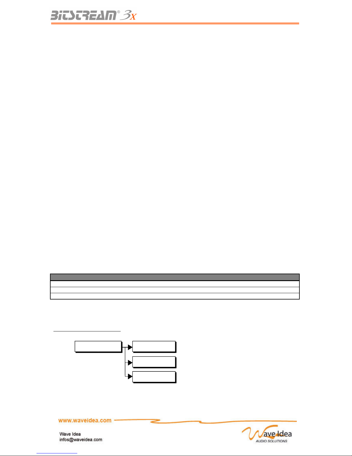
Menus associated to modes
Rev 1.1 - Page 13
Operating mode Standard
User
Selection of standard mode (pre-programmed)
Selection of User mode
Reason Selection of Reason mode
Page 14
USER MANUAL
Configuration and usage of the Bitstream 3X
The Infrared Controller
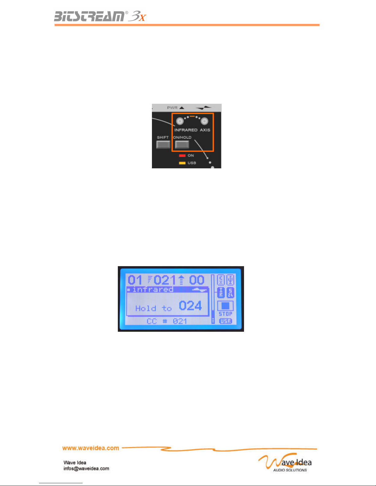
The Bitstream 3X is equipped with an Infrared controller allowing control on the Z axis (vertical). This
control is, from the point of view of functionality, considered like a slider or button, and thus it is
configured in the same manor, and is capable of generating any MIDI event.
The infrared controller calculates the distance between the machine and the hand of the user, and
transforms that distance into a value of between 0-127, assignable in a MIDI event. The distance
scanned is anywhere from 4-50 cm from the machine. The user can put his hand above the controller
and see the « infrared bar graph » which will adjust according the movements of the hand.
The MIDI will thus be generated automatically.
The « Hold » Key allows the temporary saving of an infrared value with a simple touch.
In this way, any value of the infrared controller can be saved and then modified again later at any
moment. This hold key allows the user to fix the infrared controller to a desired value before relaxing
his hand from the machine.
This key also works as the on/off switch for the controller (3 seconds long push). The LCD screen
shows whether the controller is on or off.
To use the Infrared controller, follow these steps:
- Put your hand above the controller, which will generate the MIDI events associated with the
controller.
- When a desired distance is reached, push the « Hold » button and the value will be saved
(temporarily).
- You can then remove your hand and see the saved value appear on the bar graph on the LCD
screen.
- Upon the next usage of the Infrared Controller, you can get back the saved value with the
« Hold » button and re-generate the MIDI events assigned to the controller. This mode
functions similar to the « Hook » mode used by the sliders.
Rev 1.1 - Page 14
Page 15
USER MANUAL
Menus associated to the Infrared Controller
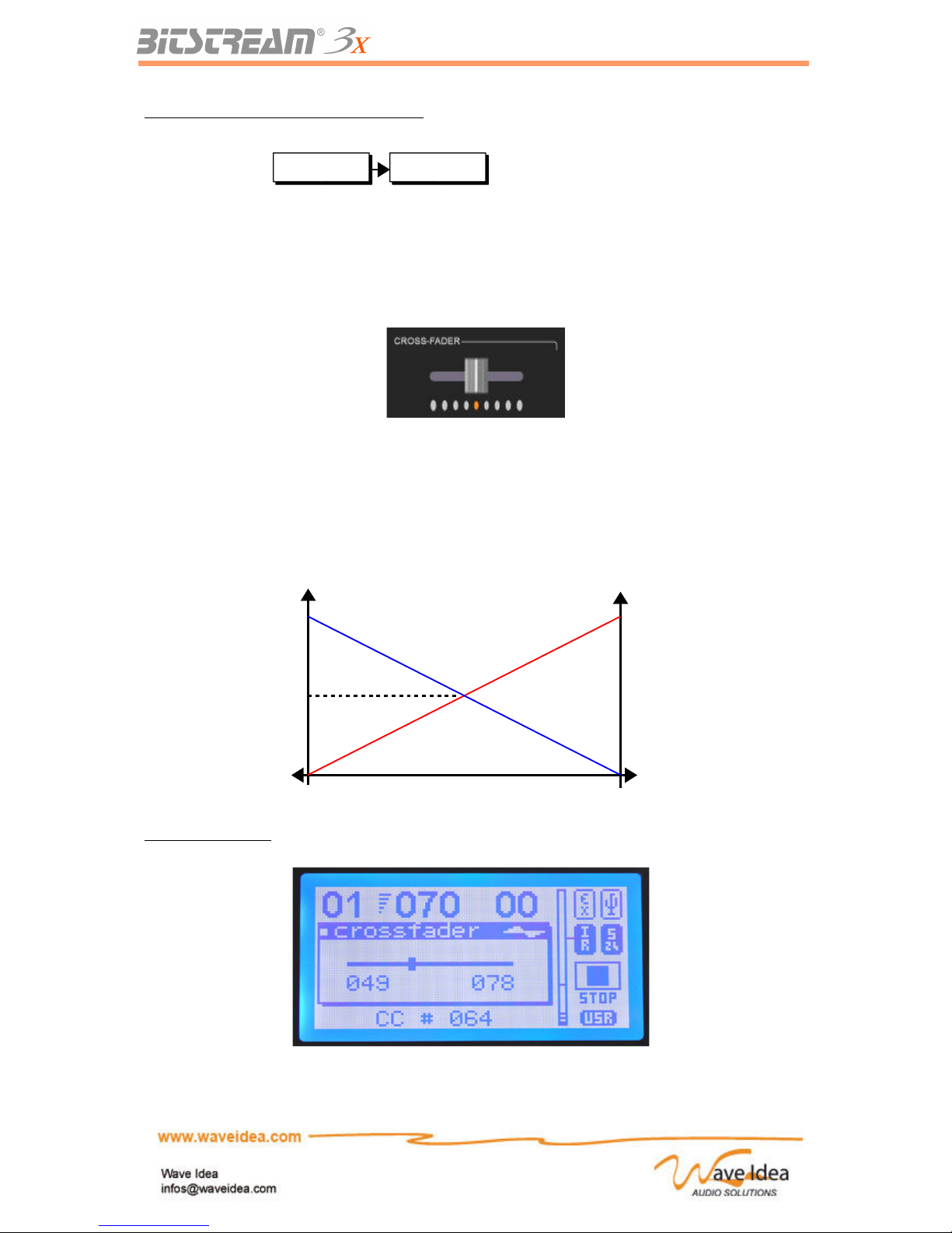
The Cross-Fader
The Bitstream 3X is equipped with a digital cross-fader, which allows the generation of 2 distinct MIDI
events, sending opposing values.
The cross-fader can be seen as 2 sliders, each having his MIDI assignment. These 2 virtual sliders
send opposing values #1 and #2 to create the function of cross-fader.
The schematic below shows the values generated by the 2 MIDI events associated with the crossfader.
Cross-fader Screen
Rev 1.1 - Page 15
Infrared On/Off
State of the infrared controller
Value #1
generated
Value #2
generated
Position of cross-fader
127
64
0
Page 16
USER MANUAL
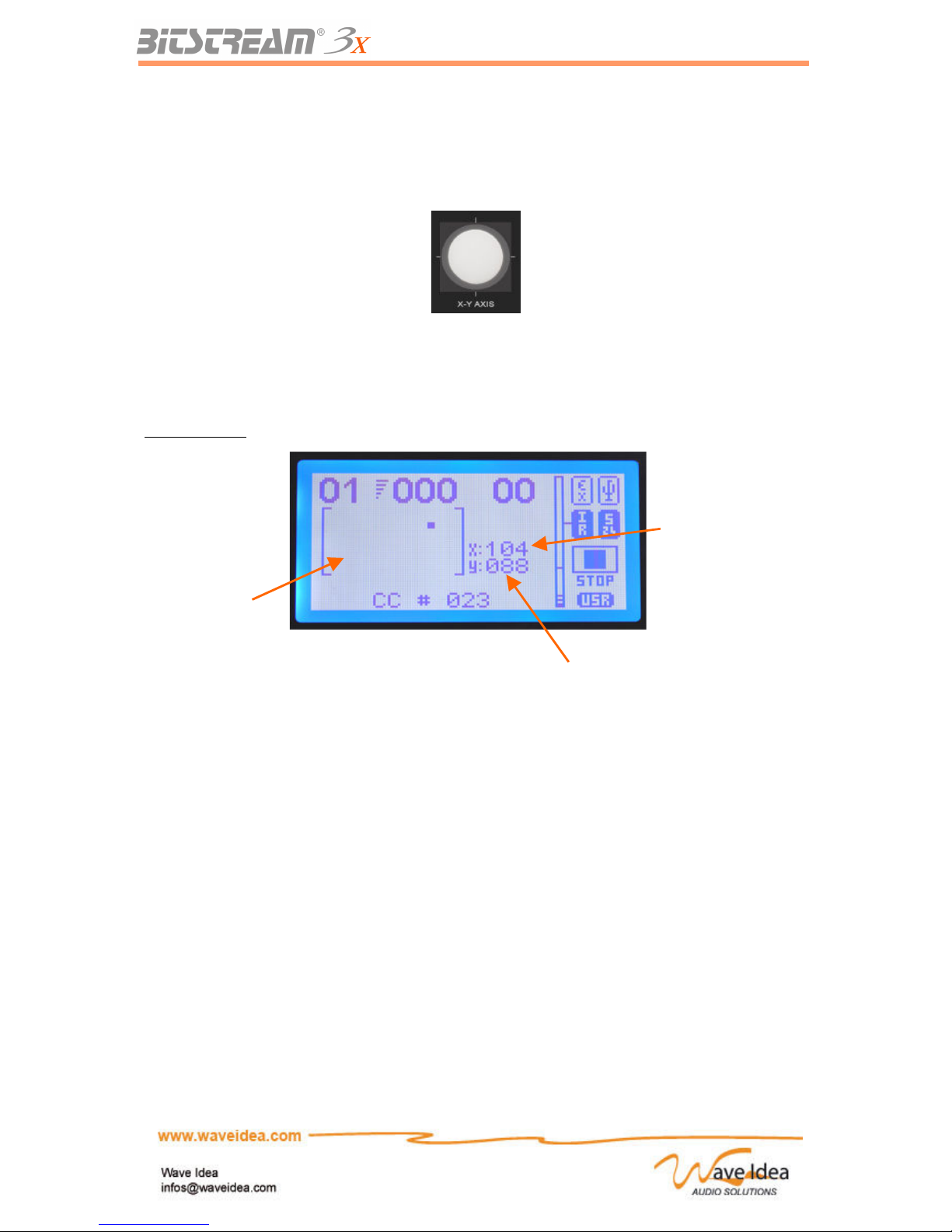
The Joystick
The Bitstream 3X is equipped with a dual axis joystick, allowing the generation of 2 distinct MIDI
events, in the same manor as the cross-fader.
These 2 MIDI events are considered as 2 distinct sliders, covering the X and Y axes (horizontal and
vertical respectively).
So, with one finger on the joystick, the user can generate 2 different MIDI events, for example, a
panoramic and volume, or other filter parameters… The joystick has a spring which allows it to go back
to its central position after use; in fact, this is the only analog control that doesn’t have a « Hook »
mode.
Joystick Screen
Selection of the «Current Function»
Role of the up-down buttons and the encoder
The up-down and encoder buttons have the same role: the selection of parameters or the changing of
the value of a parameter.
Along with modifiable parameters, which help the non-assignable controls, there are:
– The groups
– The memorized scenes
– The MIDI channels
Finally, to improve the ergonomy of the Bitstream 3X, the notion of « Current Function » is introduced.
This « current function» will be the actual function selected (along with the three listed above), which
responds to the up-down and encoder buttons.
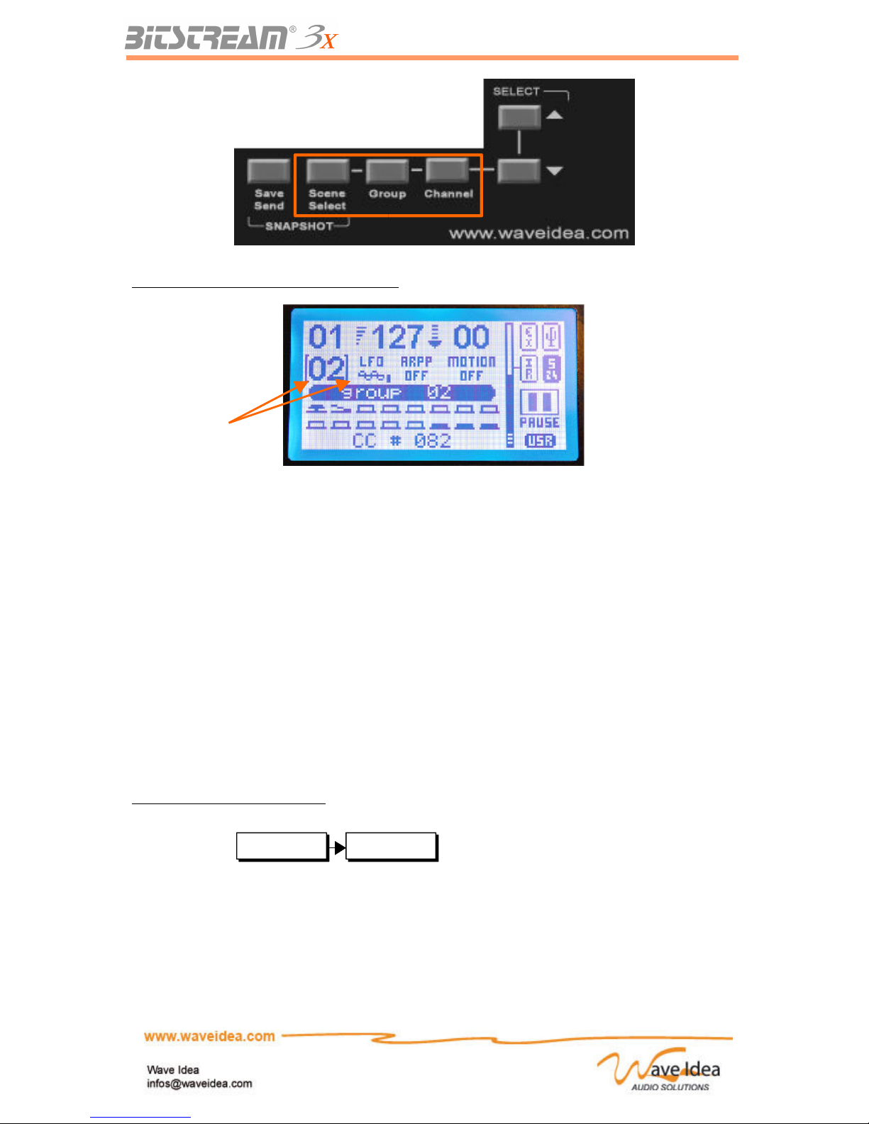
One of these functions is simply activated by the touch of the corresponding button. The screen will
indicate the active function by showing two brackets around the value of the function.
Rev 1.1 - Page 16
Graphical
Representation
of Joystick,
and position
Value of joystick on
vertical axis(Y)
Value of joystick on
horizontal axis(X)
Page 17
USER MANUAL
Example: Current function is “selected group”
Note 1: While the Bitstream 3X is in Menu Mode, the up-down and encoder button allow the navigation
of different menus as well as permit the changing of parameter values.
Selection of the group
The Bitstream 3X has 21 groups, accessible directly via the up-down and encoder button (while the
current function selected is that of the groups).
A group is a « layer » of configuration of the ensemble of the Bitstream 3X controls.
Each control included on the Bitstream 3X can generate 21 different MIDI events without being
reprogrammed.
The Bitstream 3X can be reprogrammed whenever desired by sending sysexs, without any interruption
in the music, so the assignment possibilities are therefore endless.
Note 1: the number of CC and Note controllers assigned in the standard mode are shown on the face
of the Bitstream 3X. Each increase or decrease in the group increases or decreases by 8 the Note or
CC generated.
The standard mode, therefore allows the coverage of 128 numbers of notes or CC available in MIDI.
Menus associated with the group
Selection of the MIDI channel
The Bitstream 3X can generate MIDI events on all 16 different MIDI channels, as defined by the norm.
By simply pressing the up-down buttons, while the « current function» is the MIDI channel selected,
allows the modification of the MIDI channel on which the Bitstream 3X generates its messages.
Rev 1.1 - Page 17
Group select 001 - 021
Selection of the group
Group with
indicating brackets
Page 18
USER MANUAL
The Bitstream 3X, has 2 MIDI output ports that can be selected independently by each control, it
therefore has 32 virtual MIDI channels (16 in each port).
The selection of the output port for each control is done via the « assign » menus of the Bitstream 3X,
as well as by the configuration software.
The MIDI channel of 1 to 16 can be selected directly from the user interfaces of the Bitstream 3X.
Note 1: To program a MIDI event generated on a fixed MIDI channel, independent of the Bitstream 3X,
User mode is required, the value of the MIDI channel being directly programmed in the MIDI message.
Note 2: The MIDI channels are generally numbered from1 to 16, and correspond to the MIDI channel
numbers varying from 0 to 15, or 0 to F in hexadecimal, standard notation in MIDI.
For example, a CC numbered 10 to generate on a fixed MIDI channel numbered 2 will have a
message like this: B1 0A VV with B1 = CC on MIDI channel 2, 0A = 10 in decimal, VV = value of the
CC.
Menus associated to the MIDI channel
Selection of the scene memories
The Bitstream 3X has 100 available scene memories, also called « snapshots ».
When activated, the selection of the number of the scene memory is done by using the up-down
buttons, as well as the encoder.
To save a snapshot, it is necessary to select a number via the up-down buttons or the encoder before
saving or sending the scene. After the scene is saved or sent (via the save/send button), the Bitstream
3X will show the number chosen.
For more information on this subject, refer to the dedicated chapter.
Menus associated to scene memories
Analog behaviour
Besides the joystick, which doesn’t need the analog function, all the analog function of the Bitstream
3X can be configured in 2 modes: Hook mode or Jump mode.
Jump mode allows the instantaneous sending of MIDI data no matter what position the control is in at
the time of the change.
This mode could provoke undesirable jumps in the values when the user uses the different groups of
the Bitstream 3X, the physical value of the control may not correspond to the value of the same control
in a new group.
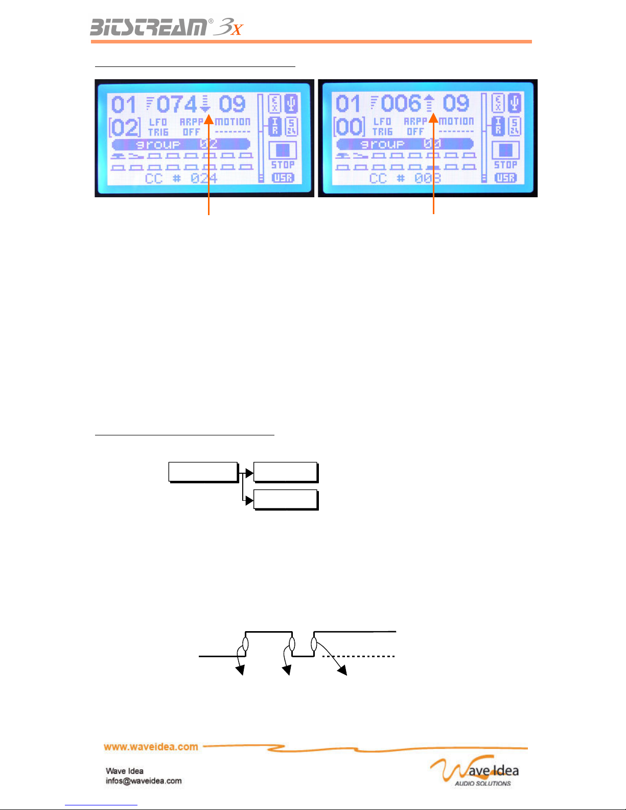
Hook mode allows the user to avoid any undesirable jump in values: After any group change, if the
physical position of the analog control doesn’t correspond to the value of the same control in the newly
selected group, the MIDI data is not sent while the physical position and the value are different. Thus,
no jump in value is obtained.
The LCD screen of the Bitstream 3X indicates the direction to move the control to finally generate the
MIDI.
Rev 1.1 - Page 18
MIDI channel 001 - 016
Selection of the MIDI channel
Scene select 000 - 099
Selection of the number of the scene
Page 19
USER MANUAL
Examples of what can be shown on the screen:
Note 1: The following analog controls involved in Hook mode:
- 32 rotatives potentiometers
- 8 sliders
- 1 infrared controller (by using the Hold key)
Note 2: The selection of the analog behaviour is done via the menus of the Bitstream 3X
Note 3: This parameter concerns the 2 modes of the Bitstream 3X, Standard and User.
Note 4: The Hook mode is the default mode
Note 5: The Hook mode is an excellent alternative to the motorized MIDI controllers.
Menus associated to the analog behaviour
Digital Behaviour
Each of the 16 digital assignable controls presented on the Bitstream 3X independently have 2
behavioural modes: the modes « Push » and « Toggle ».
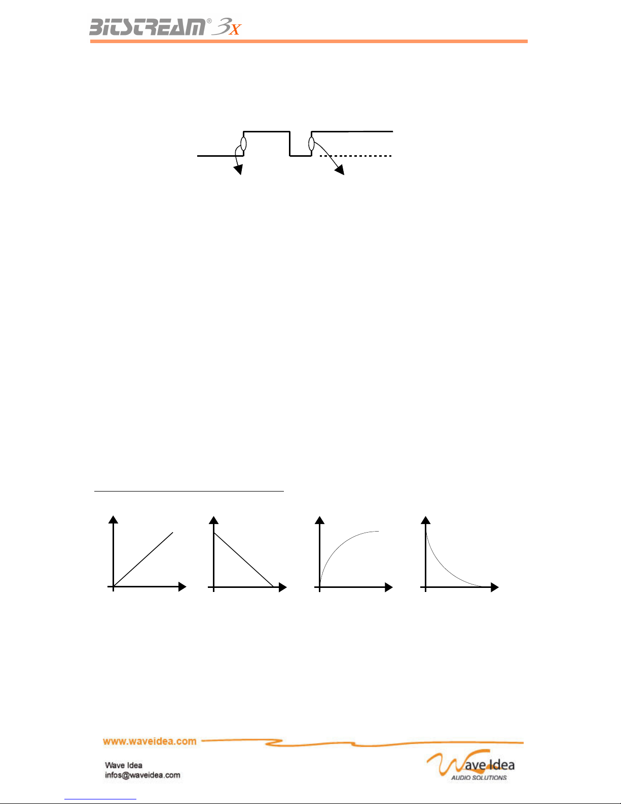
Push mode is the « instantaneous » mode where all the changes of the state of digital control
produces a MIDI message.
This mode is principally used as a mute function for the short term or to trigger an action to the
Rev 1.1 - Page 19
State of digital
control
Send Max
value (127)
Send Min
Value (0)
Send Max
Value (127)
Button Pushed
Button
Released
Analog mode Jump
Hook
Selection of Jump mode
Selection of Hook mode
Here the physical
position is higher
than the value in
the selected group
Here the physical
position is lower
than the value in
the selected group
Page 20
USER MANUAL
software / material being used.
Toggle mode can also be programmed. In this case, at each transition from 0 to 1 (released/pressed),
the MIDI will be sent and the opposite value will be assigned.
Toggle mode is the default. It will probably be used when the buttons are programmed for the standard
mute functions.
List of the 16 digital controls concerned by the modes Push / Toggle:
- 8 assignable buttons
- 1 button on the joystick
- 1 button on the encoder
- 1 footswitch
- 5 transport buttons (used with SHIFT active)
Curve Models
Another strength of the Bitstream 3X: each analog control can vary according to the 7 curve models.
The variation given by an analogue control can evolve according to the model:
- Linear
- Inverse linear
- Logarithmic
- Inverse logarithmic
- Random
- User 1
- User 2
Graphical representation of the curve models
The curve called « Random » allows the sending of a MIDI event, being a random value at each
change of the analog control.
The User 1 and User 2 curves are programmable such that the user can give any value to each of the
128 positions of the analog control.
For more information about the modes User 1 and User 2, see the section for the configuration
software of the Bitstream 3X.
Note 1: The linear curve is the model by default.
Rev 1.1 - Page 20
State of the
digital control
Send Max (127)
value
Send Min (0)
value
Button Pushed
Button
Released
Linear
Inv. linear Logarithmic Inv. logarithmic
Page 21

USER MANUAL
Note 2: The models of the curves are available for the User mode of the Bitstream 3X.
The standard mode allows only the linear variation of the analog controls.
Examples of usage :
- Logarithmic variation to control a volume
- Inversion of sent MIDI values
- Generation of random MIDI sequences
MIDI and USB Inputs
The Bitstream 3X has one MIDI input on the standard connector, as well as one USB input.
Each of these inputs plays the same role and could be routed towards:
- MIDI out 1 on connecter MIDI
- MIDI out 1 on USB
- SYNC-24 out
- Internal functions of the Bitstream 3X (LFO, Arppeggiator, …)
Besides the function of MIDI controller, the Bitstream 3X can be used as a:
- USB – MIDI converter
- MIDI – SYNC-24 converter
- USB – SYNC-24 converter
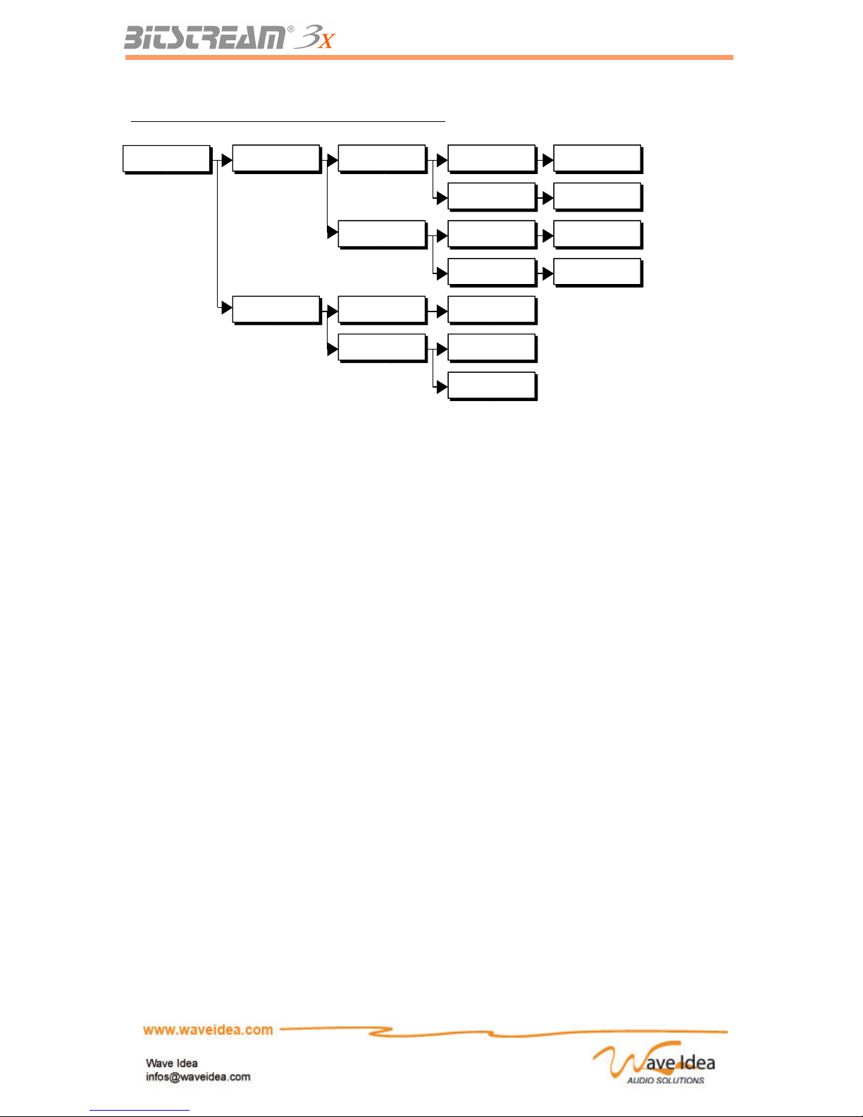
The routing of the different MIDI inputs is done across the menus of the Bitstream 3X for each of these
functions.
Each of these MIDI inputs is not exclusive, except for the functions that necessitate a real-time MIDI
clock.
Also the 2 inputs MIDI and MIDI USB can be re-routed at the same time towards a MIDI out 1. The
possibilities of the Bitstream 3X extend so that it can be integrated into any MIDI environment.
The MIDI inputs also feature MIDI filters allowing the elimination of real-time messages often unused
which overloads the MIDI bus. The filters are also accessible by the menus; see the complete routing
schematic below.
Note 1: The real-time messages are treated separately from the MIDI messages, allowing a better
fluidity and a further extension the possibilities of the Bitstream 3X.
The real-time messages (clock / start / stop / continue) are necessary for the different functions of the
Bitstream 3X which are synchronisables from an external module (Arppeggiator, LFO, motion
sampler).
Finally to ensure no limit, each function uses its real-time MIDI source independently. For example the
user could synchronize the arppeggiator from the MIDI connector « In », while synchronizing an
external SYNC-24 synthesizer from the MIDI input on USB.
Note 2: The selected MIDI input, by default, is the one that corresponds to the MIDI connector.
Rev 1.1 - Page 21
Page 22
USER MANUAL
Routing of the MIDI inputs by the Bitstream 3X menus
MIDI and USB Outputs
The Bitstream 3X has 2 distinct MIDI outputs, repartees on 2 MIDI connectors and 2 MIDI on USB.
One MIDI output Thru is also available. This Thru output drives the same signals as the MID input, and
allows the user to integrate the Bitstream 3X in its MIDI environment.
Each control (slider, button …) or function (LFO, Arppeggiator …) of the Bitstream 3X can generate
MIDI events through the different MIDI and USB outputs available.
Also, the user could, for example, direct the MIDI events from the slider n°1 towards the USB on MIDI
out 1, the MIDI events of the LFO towards the MIDI out 2, and do this independently for each control
and function integrated into the Bitstream 3X.
The double MIDI outputs offer virtually 32 MIDI channels (16 per output), and again allow the
integration of the Bitstream 3X into a complex MIDI environment.
The configuration of the MIDI outputs for each of the controls is done via the « Assign » menus of the
Bitstream 3X, as well as via the dedicated configuration software.
Note 1: The choice of the MIDI outputs for each control is available in each of the 2 modes, Standard
and User.
Rev 1.1 - Page 22
MIDI Config
MIDI Merger Merger Src MIDI In On/Off
USB In On/Off
Merger Dst MIDI Out 1 On/Off
USB Out 1 On/Off
MIDI Filter Filter state
On/Off
Filter type
All events
Realtime
Usage of MIDI In
Usage of USB In
MIDI Inputs towards
MIDI Out 1
MIDI Inputs towards
USB Out 1
MIDI Filter
All MIDI messages are filtered
Realtime MIDI events are filtered
Page 23
USER MANUAL
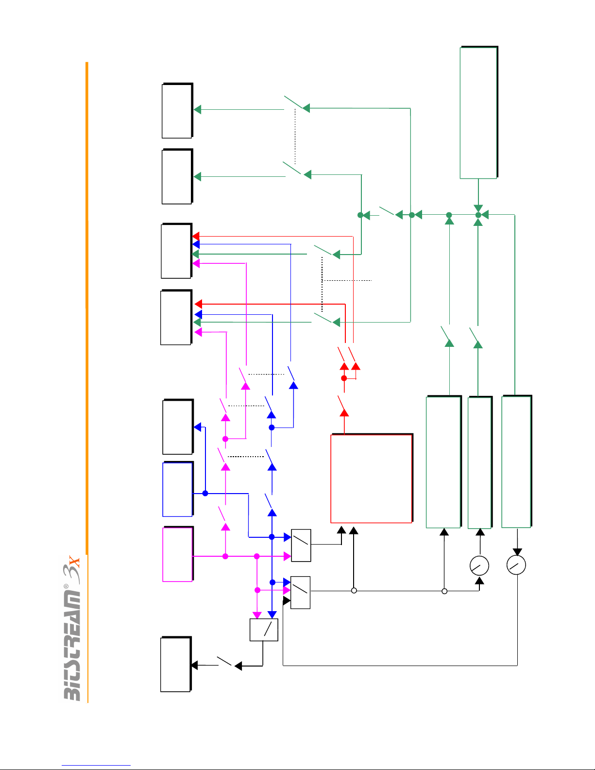
Complete Schematic of the MIDI and USB Routing
Midi out 2 enable
(ctrl assign)
MIDI IN MIDI
THRU
MIDI
OUT1
MIDI
OUT 2
USB IN
USB
OUT1
MIDI FROM 3X
CONTROLS
ARPPEGGIO
USB
OUT2
SYNC
24
LFO
MOTION
SAMPLER
Sync24 source
realtime source
arpp source
notes
sync
sync
Merger_dst_midi
Merger_dst_usb
Lfo frequency
Merger_src_usb
Merger_src_midi
Midi filter
Midi out 1 enable
(ctrl assign)
USB out enable
(ctrl assign)
Arpp_dst_midi
Arpp_dst_usb
Arpp_state
Motion_state
lfo_state
Sync24 state
sync
TRANSPORT
BAR
sync
tempo
Internal sync
Page 24

USER MANUAL
The preceding schematic illustrates the MIDI and USB routing possibilities of the Bitstream 3X.
Each parameter visible on the schematic is accessible via the menus of the Bitstream 3X, and/or from
the delivered configuration software.
Chain of Controls
Several controls on the Bitstream 3X can be chained together to allow the simultaneous sending of
several MIDI events by using just one control.
Once one control is chained to another, it can be configured as a cross-fader. This function allows the
chained control to send the opposing value to the control source.
This function permits the creation of virtual cross-faders by a simple configuration.
Example of Usage
The creation of a group of 4 « sliders » from slider 1, of which the last two (3 and 4) send opposing
values:
– Slider 1 chained to slider 2
– Slider 2 chained to slider 3 [With cross-fader function]
– Slider 3 chained to slider 4 [With cross-fader function]
Once the user changes the value of slider 1, 4 MIDI messages will be generated and sent
successively, the MIDI message of slider 1, that of slider 2, that of slider 3 with an opposing value, that
of slider 4 with an opposing value.
If the user changes the value of slider 3 for example, the MIDI message will be generated and the MIDI
message of slider 4 will be equally generated with the opposing value, as these two controls are
chained with the cross-fader function.
Note 1: The chaining of these controls is unlimited, but caution – do not « over-chain » the controls,
because of the risk of saturating the MIDI bus, notably if the other functions generate many MIDI
events (3 automations) which are currently running.
Note 2: The chaining of these controls can be configured either by the Assign menu, or by the
configuration software.
Assigning MIDI events to the controls of the Bitstream 3X
Standard versus User Mode
Two modes are available on the Bitstream 3X, Standard and User, and could easily be called « Preprogrammed » and « to be programmed ».
In effect, the standard mode is perfectly adapted to the uses of the Bitstream 3X with software
synthesizers, such as Reason, Native Instrument, Live and others.
The user also has the possibility of changing some of the parameters of standard mode – see the
following chapter.
The user mode is made for the users that want to modify the parameters associated to each control. It
is mainly used when the soft or hardware to control does not respond to standard MIDI CCs or Notes.
Using the Configuration Software
The configuration software of the Bitstream 3X allows the modification of all the parameters of
standard and user mode, without difficulty. The software gives access to all the parameters for each
control, and allows the programmer to modify them with a simple click of the mouse.
Rev 1.1 - Page 24
Page 25
USER MANUAL
Using the « Assign » menus
The assign menus of the Bitstream 3X are used to re-program the controller without using the
configuration software.
Note: Certain complex parameters cannot be modified from the assign menus, but only from the
configuration software.
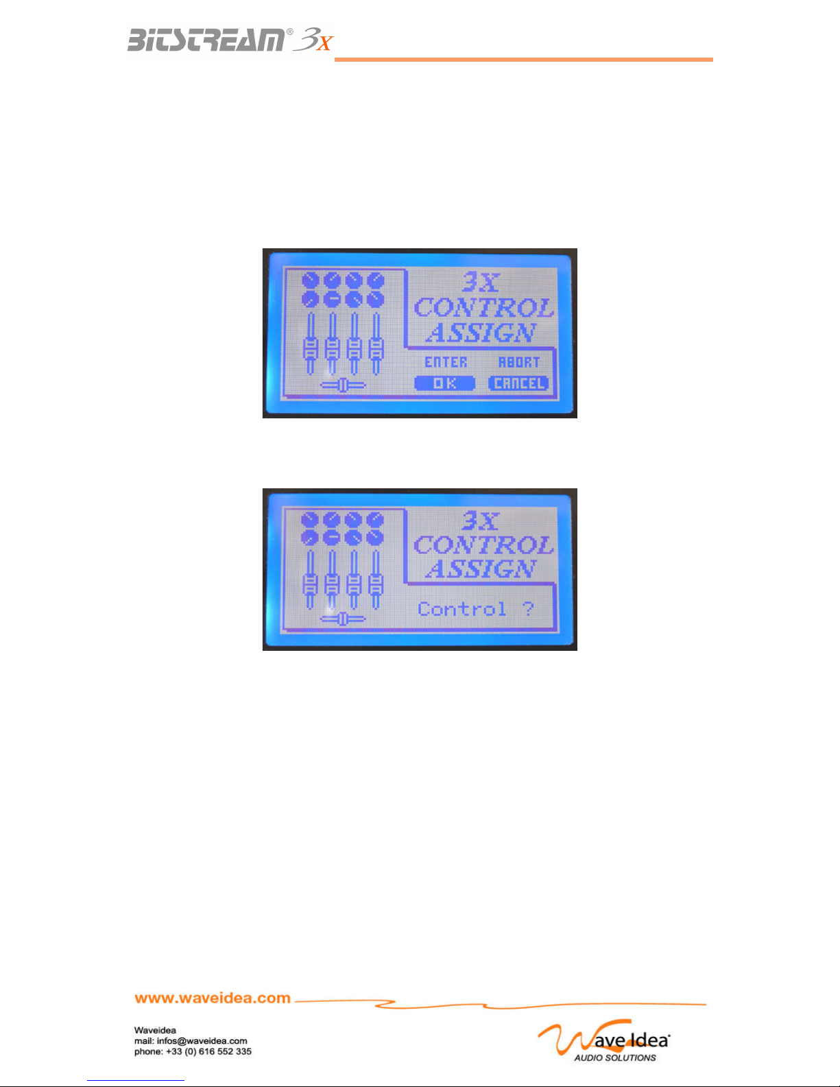
To access the assign menus, use the EDIT key, pressing it two times. The following screen will
appear:
The OK button will validate the access, and CANCEL takes you back to the normal screen
Once the user presses OK, the following screen will appear:
The Bitstream 3X is now waiting for the user to change the position of the control being assigned, and
enters automatically into the assign menu of the control being configured.
The navigation of this assign menu is similar to the navigation of the other menus of the Bitstream 3X.
They are organized into a hierarchy, and navigation is done with the UP, DOWN, OK and CANCEL
keys. See the menu-dedicated chapter for more information.
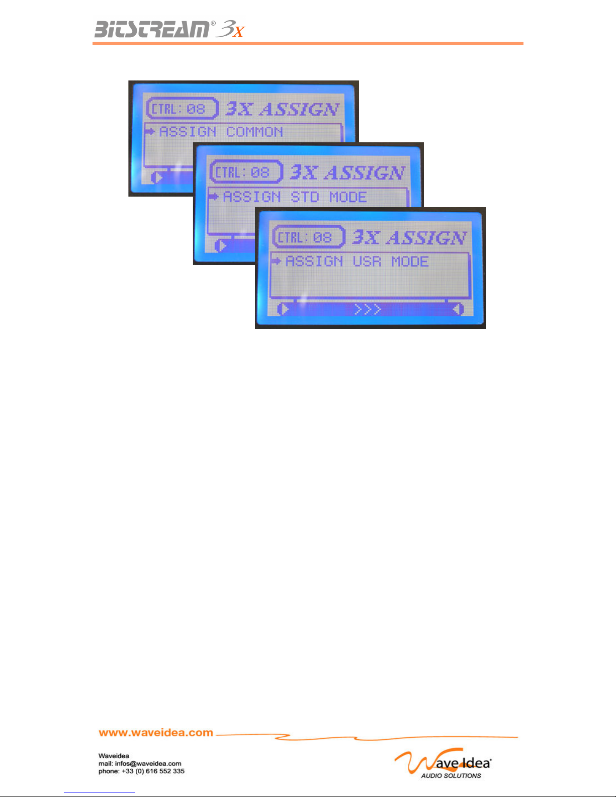
For each control, three menus are available:
- Assign common Parameters common to both standard and User modes
- Assign Standard Parameters reserved for standard mode
- Assign User Parameters reserved for user mode
Rev 1.1 - Page 25
Page 26
USER MANUAL
The different parameters accessible through these three high level menus are described below.
Configuration of the controls of the Bitstream 3X
MIDI events associated with the Standard mode
The MIDI events assignable in standard mode can be one of two types:
- Control change (CCs)
- Notes (Nts)
These two types of MIDI messages are perfectly compatible with the synthesizer software such as
Reason, Ableton Live and others.
MIDI events associated with User mode
The MIDI events assignable in User mode are listed in the MIDI standard:
- Control change (CCs)
- Program change (PCs)
- Notes
- RPN
- NRPN
- Sysexs
- MMC
- ...
For more information, see the chapter on MIDI standards at the end of this manual.
The usage of these more complex MIDI events is generally geared toward the control of the
synthesizer software or hardware which is not compatible with the standard messages, type CC or
Note.
Rev 1.1 - Page 26
Page 27
USER MANUAL
The common parameters in Standard and User modes
The following parameters apply to both operating modes of the Bitstream 3X, such that a change in
one of these parameters will take effect no matter which mode is being used.
Selection of MIDI and USB Outputs
This parameter allows the user to define from which outputs the
MIDI events are generated
The different choices are as follows:
Send to Midi out 1
Send to Midi out 2
Send to USB out
Note 1: This parameter is configured independently for each control of the Bitstream 3X
Note 2: If a MIDI message should be sent from USB Out 2, the user should configure the two
parameters MIDI out 2 and USB Out from ON
Note 3: After a factory reset, all the available outputs are enabled for each control of the Bitstream 3X.
“Auto-send”
This parameter indicates if the control concerned should be sent
from the MIDI outputs during the booting up of the Bitstream 3X.
This function is generally used to automatically configure the software or the controlled synth, in effect
the values of the controls concerned are sent during the booting up of the Bitstream 3X, also, the
software or the synth controlled positions it’s different controls in the same way as the on the Bitstream
3X
Note 1: This parameter is configured independently for each control of the Bitstream 3X
Note 2: The default auto send value is disabled for all controls
Exclusion of a control of scene memories
This parameter allows the exclusion of a control of the Bitstream
3X from the functions of scene memories. Once this parameter is
ON, the corresponding control won’t be saved or recalled during the usage
of scene memories.
This function is generally used to avoid modifying the value of certain controls while using the scene
memory function.
Note 1: This parameter is configured independently for each control of the Bitstream 3X
Note 2: The default value is disabled for all controls
Rev 1.1 - Page 27
Standard √
User
√
Outputs
Standard √
User
√
Auto-send
Standard √
User
√
Scene exclude
Page 28
USER MANUAL
Digital Behaviour
This parameter defines the behaviour of the different digital controls
Available on the Bitstream 3X. The available choices are:
Push
Toggle
These different modes are described in this manual – see the dedicated chapters
Note 1: This parameter is configured independently for each control of the Bitstream 3X
Note 2: The default value is “Toggle” for all digital controls
The parameters dedicated to Standard mode
The following parameters are dedicated to the Standard mode of the Bitstream 3X.
Number of the CC or Note
The Bitstream 3X in standard mode can generate control change
or Note messages depending on the configuration chosen.
The user can modify the number of the CC or Note to be generated,
choosing from among the 128 possibilities defined by the MIDI standard
Note 1: This parameter is configured independently for each control of the Bitstream 3X
Note 2: The default value is “CC” for all controls, the associated number are described at the beginning
of this manual.
The parameters dedicated to User mode
The following parameters are dedicated to the user mode of the Bitstream 3X. This means that if a
parameter needs to be reconfigured to be compatible with the software or controlling synth, user mode
is required.
Min & Max values
These two distinct parameters allow the reduction of the range of
analog and digital controls on the Bitstream 3X.
The MIDI standard authorizes the values from 0 to 127 (7 bits) for each control, but the user can
reduce these values with a parameter for Min & Max associated to each control, for each of the 21
groups.
Note 1: When reducing the range of the control being configured, the whole physical range is redefined, so the potentiometer for instance continues using its whole range even if its range in values
has been reduced
Note 2: The default values are 0 for Min and 127 for Max values
Rev 1.1 - Page 28
Standard √
User
√
Digital behav.
Standard -
User
√
Min & Max
Standard √
User
-
CC/Nt number
Page 29
USER MANUAL
Selection of the MIDI Delay
This parameter allows the user to insert a delay after each MIDI
Message generated by the control concerned.
It is generally used with the synths receiving from exclusives systems
sent by the Bitstream 3X, in order to allow time to treat them.
This parameter should be kept weak in order to have the best fluidity and shouldn’t be raised unless
the synth or the software requires the insertion of a delay
The different choices available are:
0 (no delay)
30 ms
60 ms
90 ms
Note 1: This parameter is configured independently for each control of the Bitstream 3X
Note 2: The default value is set to 0 (no delay) for each control
Curve Models
This parameter defines the behaviour of the different analog controls
on the Bitstream 3X. The model of an analog control
can vary in different ways, among which:
Linear (default mode)
Inverse linear (the control at maximum generates the minimum value)
Logarithmic
Inverse Logarithmic
Random (The control generates a random value no matter what its position)
User 1 and User 2 (The user redefines the sent value at each position of the control)
These different modes are described in this manual, see the dedicated chapters.
Note 1: This parameter is configured independently for each control of the Bitstream 3X
Note 2: This parameter concerns only the User mode, the standard mode is already configured on
Linear
Note 3: The default value is set to “Linear” for each control
Checksum Management for exclusive systems
The Bitstream 3X is capable of generating exclusive systems
(SYSEXs) in user mode. Certain synths or software capable of
receiving sysexs require the reception of an integrated checksum
in the sysex, in order to proceed to an eventual error correction.
A checksum is an integrated number in the end of a sysex, just before the end marker sysex F7h. This
number is calculated by a known algorithm, defined by a standard. This calculation is the sum of the
octets preceding the checksum, modulo 128.
From the controlling synth, the position of the first byte which needs to be taken into account for the
calculation of the checksum (called « checksum first byte position ») can vary, so that this first octet is
configurable on the Bitstream 3X, in order to make it compatible with all the synths in the market.
If the value of this parameter is 0, the Bitstream 3X will not integrate the checksum in the generated
sysex, if the value is different than 0, it will correspond with the position of the first byte in the MIDI
chain to be taken into account for the checksum.
Rev 1.1 - Page 29
Standard -
User
√
MIDI delay
Standard -
User
√
Curves
Standard -
User
√
Checksum
Page 30
USER MANUAL
Example: The sysex to assign is: F0 00 20 4F 10 20 30 CS F7 where CS = checksum
If the calculation of the checksum only takes into account the octets 10 20 30 the
value « checksum first byte position » should be 05 (as the first octet to take into
account is the position 5, the beginning of the sysex F0 being at position 1)
Note 1: This parameter is configured independently for each control of the Bitstream 3X
Note 2: This parameter only concerns user mode, standard mode does not allow the generation of
exclusive systems.
Note 3: The default value of this parameter is set to 0 (no checksum)
Chaining the Controls
In user mode, the user has the possibility to chain different controls
of the Bitstream 3X, in order to create groups.
As well, if several controls are chained, the modification of one value will generate MIDI messages
associated with all the chained controls.
These groups or chains are generally used when the user wants to control an ensemble of MIDI
messages having the same value, by only modifying one control.
The number of the control to chain can vary from 0 to 65 (see the section on the numbering of the
controls in the beginning of this manual), 0 means that none of the controls are grouped.
Another very interesting parameter concerning the creation of chained controls is the possibility to
create virtual cross-faders (chained controls send opposed values). Some examples:
Example 1 Creation of a group of 3 sliders number 2, 3 and 4
Once the user modifies the slider 2, the MIDI messages from the sliders 3 and 4 will be automatically
generated, with the same value as slider 2.
For this example, the user will chain slider 2 with slider 3, and slider 3 with slider 4, so that a group of 3
controls is created.
Note: With this example, once the user modifies the value of slider 3, which is connected to 4, two
MIDI messages will be sent, corresponding with 3 & 4.
Example 2: Creation of a virtual cross-fader between sliders numbered 40 and 41
Once the user modifies the slider 40, the MIDI messages of the sliders 40 and 41 will be automatically
generated, with the opposing values to create a virtual cross-fader.
For this example, the user will chain 40 with 41, taking care to configure the parameter « cross-fade »
ON
Note 1: This parameter is configured independently for each control of the Bitstream 3X
Note 2: This parameter only concerns user mode, as standard mode doesn’t allow the chaining of the
controls of the Bitstream 3X
Alphanumeric LCD Chain
In User mode, the user has the possibility to assign an alphanumeric chain
to each control available on the Bitstream 3X, which will be displayed on the
LCD as soon as the value of the control is modified.
This parameter allows the user to see what’s going on, since it could be confusing configuring all the
controls of the Bitstream 3X. Also, for each control, the user assigns a 16 character message which
will be displayed on the last line of the LCD. This message can recall the name of the synth or software
associated with the control (in case there are several which are controlled by Bitstream 3X), as well as
the name of the parameter being used for the control.
Rev 1.1 - Page 30
Standard -
User
√
Chaining
Standard -
User
√
LCD string
Page 31
USER MANUAL
Example: The use controls the « cut-off » of the filter of the track 4 of a Roland Mc303, the LCD chain
can thus be defined like this: « MC303 CUTOFF TR4 », also, this chain will be displayed as soon as
the user modifies the control concerned; the parameter that was previously assigned will be recalled.
Note 1: This parameter is configured independently for each control of the Bitstream 3X
Note 2 : This parameter can only be used in user mode as standard mode doesn’t allow the
redefinition of LCD chains, which are fixed on « NT/CC #XXX », where NT=Note, CC=control change
and XXX the number of the note or control change generated (Notes and control changes are the only
two parameters configurable in standard mode)
MIDI Channel
The MIDI channel on which the Bitstream 3X generates its messages
can be fixed on a value defined by the user, being that which is selected
currently (Configured by the dedicated buttons on the face of the Bitstream 3X),
(example 2), the MIDI channel can also be fixed to a certain value and ignored from the currently
selected channel of the Bitstream 3X (example 1)
Example 1: Generation of a CC 8 on fixed MIDI channel 1
The user will decry the MIDI chain corresponding to the CC 8 like this: B0 08 VV
0 represents the MIDI channel – 1 (in effect the MIDI channels go from 1 to 16, they are coded from 0
to F in hexadecimal in the MIDI chain, MIDI channel N is therefore represented par N-1 in the chain)
This parameter accessible via the configuration software is called « MIDI channel position », in the
example below, the MIDI channel being fixed, it will be regulated to 0 so the Bitstream 3X doesn’t
integrate it’s own MIDI channel in the chain.
Example 2: Generation of a CC 4 on a modifiable MIDI channel
The user will decry the MIDI chain to CC 4 like this: BN 04 VV
N represents MIDI channel – 1 (in effect the MIDI channels go from 1 to 16, they are coded from 0 to F
in hexadecimal in the MIDI chain, MIDI channel N is therefore represented par N-1 in the chain)
This parameter accessible via the configuration software is called « MIDI channel position », in the
example below the MIDI channel should be inserted by the Bitstream 3X into position 1 in the chain.
The « MIDI channel position » value will therefore be 1 in this example.
The second example gives the user the possibility to generate MIDI events on the 16 possible
channels defined by the MIDI standard by simply modifying the value of the MIDI channel from the face
of the Bitstream 3X.
Note 1: This parameter is configured independently for each control of the Bitstream 3X
Note 2: This parameter concerns only the user mode, as the standard mode generates the MIDI
events always on the MIDI channel of the Bitstream 3X
Note 3: In using the MIDI channel of the Bitstream 3X instead of a fixed MIDI channel, the user can
control the different synths or software which will be configured to respond on a single MIDI channel.
Also, the synth or software currently selected can be modified by a simple change of the MIDI channel
of the Bitstream 3X
Note 4: From firmware V1.4 and higher, the SHIFT button can prevent the Bitstream 3X from inserting
its own MIDI channel in the MIDI string, even if “MIDI channel position” is different of zero
MIDI String
The MIDI string describes the MIDI event the Bitstream 3X will generate.
Rev 1.1 - Page 31
Standard -
User
√
MIDI Channel
Standard -
User
√
MIDI String
Page 32
USER MANUAL
This string can be programmed by the user when using the Bitstream 3X
“User defined mode”, only via the dedicated configuration software.
It can be up to 21 bytes long, each control of the Bitstream 3X disposes of its own MIDI string, for each
of the 21 groups of the Bitstream 3X.
This string is always defined using the hexadecimal format, as described in the MIDI specification.
Note: If you are not familiar with the MIDI events and their hexadecimal representation, the
configuration software provides some predefined templates, which will help you to fulfil the MIDI string
with all the standard MIDI events.
Example of MIDI string : Sysex
According to the MIDI specification, a sysex always starts with F0 and ends with F7.
Example : F0 10 20 30 40 50 00 00 F7
If the above MIDI string is assigned to a control of the Bitstream 3X, then each time the user tweaks
this control, the Bitstream 3X will generate this sysex MIDI event and send it to the different MIDI and
USB outputs.
Control value positions 1 & 2
The MIDI string described above may contain the value of the control
to which this MIDI string is assigned.
The Bitstream 3X can insert the control value in two different location on the MIDI string, respectively
called Control value position 1 and 2.
For instance, if the above MIDI sysex is assigned to the infrared controller, each time the user changes
the value of the infrared controller, this value has to be inserted in the MIDI string at position V1.
F0 10 20 30 40 50 V1 V2 F7
position 1 2 3 4 5 6 7 8 9
Therefore the control value position 1 must be 7 so the value of the infrared controller will be inserted
at position 7.
Another position can be programmed (control value position 2), if it must be inserted the V2 location,
then the control value position 2 will be 8
Note 1 : programming a control value position 1 or 2 to zero will result in no control value inserted into
the MIDI string.
Note 2 : Control values position 1 & 2 can be programmed through the Bitstream 3X configuration
software.
Split control value
The above control values are defined as 7bits data, ranging from 0 to 127
according to the MIDI specification.
It may arrive some synths require this value to be splitted in 2 nibbles, (the evolver synth for instance),
in this case, the user must activate the “split control value” option from the configuration software.
The Bitstream 3X will generate a splitted control value, and insert these nibbles on control value
positions 1 and 2.
For example, the infrared controller value is 45h in hexadecimal, the splitted values will be 04h and
05h, respectively inserted at control value position 1 and 2.
Note : If the synth requires the splitted values MSB first, simply ensure control value position 1 is lower
than control value position 2, or vice versa.
Rev 1.1 - Page 32
Standard -
User
√
Control pos.
Standard -
User
√
Control split
Page 33
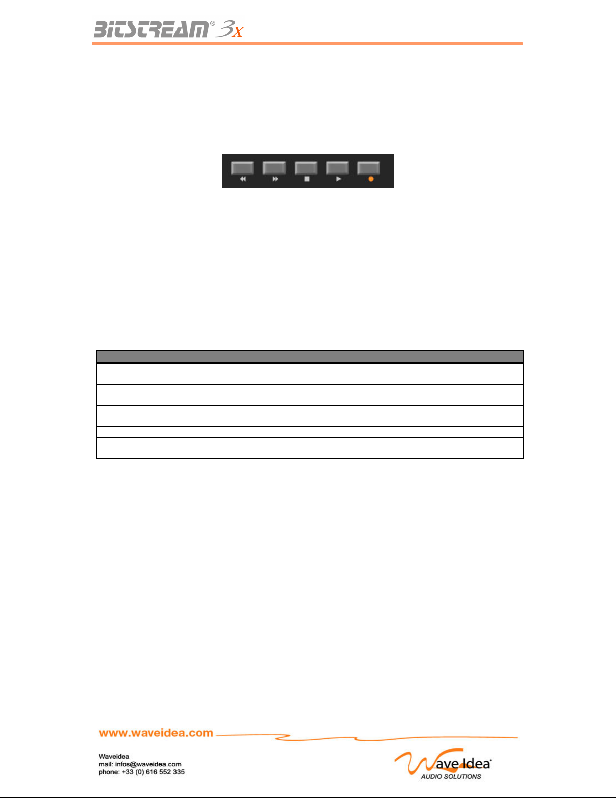
USER MANUAL
The Transport Bar
The transport bar on the Bitstream 3X allows the machine to play the role of digital sequencer, capable
of controlling any instrument or MIDI software that responds to real time synchronization events.
Also, the Bitstream 3X is capable of being the instrument master of a MIDI system, the user uses this
bar to play the other MIDI instruments at the same time, without losing synchronization.
Configuration
The transport bar has 5 buttons:
- Backward (to move a position marker backward for example)
- Forward (to move a position marker forward, for example)
- Stop (to stop a musical sequence, for example)
- Play (to play a music sequence for example)
- Record (to record a music sequence for example)
The usage of these five buttons differs from the usage of the other assignable buttons. The principle
differences are listed in the table below:
Transport buttons Assignables buttons
Assigning of event MIDI √ √
Number of available groups 1 21
MIDI events in standard mode CC/Notes + Real-time CC/Notes
MIDI events by default in user mode MMC + Real-time CC
Usage of the SHIFT key Become standard
assignable buttons
Become standard
assignable buttons
Digital behaviour Push Push/Toggle
LCD assignable chain in user mode - √
Other functions Trig automation functions -
Like all the other digital controls, the transport bar function under the two operating modes of the
Bitstream 3X: Standard and User.
In Standard mode, the transport functions generate the CC/Note 0 to 4, whereas in User mode, the
assigned MIDI events are the messages of MMC (Midi Machine Control). It is understood that the
possibility to modify the assignments to adapt the buttons to a specific MIDI environment, exists.
According to the preceding table, when the SHIFT key is active, the 5 buttons becomes assignable
buttons operating on all 21 groups of the Bitstream 3X
Synchronization of the Bitstream 3X
The transport buttons generate the MIDI events in the same manor as the other digital controls, with
several differences described in the preceding paragraph, but these transport buttons generate as well,
MIDI events in real-time, when the internal synchronization of the Bitstream 3X is turned on.
The real-time MIDI events generated by these buttons are as follows:
- Real-time Clock (message MIDI 0xF8) – permanent
- START Signal (message MIDI 0xFA) – when play is pressed
- STOP Signal (message MIDI 0xFC) – when stop is pressed
Also, the Bitstream 3X is capable of generating real-time MIDI events in order to synchronize the
sequencers and other synchronisables instruments, and also, the internal automation functions of the
Rev 1.1 - Page 33
Page 34
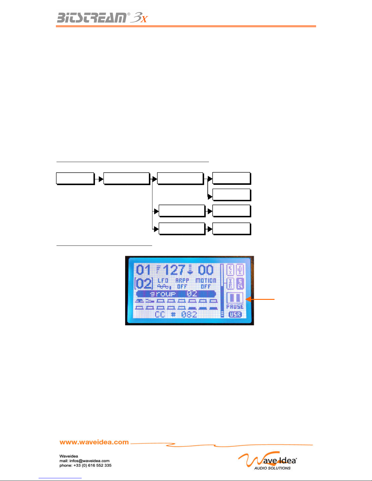
USER MANUAL
Bitstream 3X.
The different functions of the Bitstream 3X requiring MIDI synchronization include the automation
functions (LFO, Arppeggiator, Motion sampler). Each of these 3 functions have, independently, their
own method of synchronization (internal or external), accessible via the menus of the Bitstream 3X.
For instance, the user has the possibility to synchronize the LFO by the real-time messages received
from the MIDI input, the arppeggiator by the real-time messages received from the USB input, and the
Motion Sampler from the internal clock of the Bitstream 3X.
The different methods of synchronization offered are not exclusive; all the possibilities are authorized
and usable at the same time, which makes the Bitstream 3X very powerful in terms of synchronization.
Note 1: If one of the three automation functions should be internally synchronized, the Internal
Synchronization should be turned on, so that the Bitstream 3X generates the synchronization signals.
Note 2: The range of the internal tempo can vary from 30 to 250 BPM (Beats per Min), accessible from
the menus of the Bitstream 3X.
Menus associated to the synchronization of the Bitstream 3X
Screen dedicated to the Transport bar
Usage of standard buttons
The five transport buttons can be equally used as standard assignable buttons, in the same way as the
other eight.
To use these five buttons as assignable buttons, press the SHIFT key at the same time as one of the
five.
When the shift key is active, these five buttons become completely independent of their Play/Stop
mode, and are now available for the 21 groups of the Bitstream 3X, completely assignable in User
mode.
Rev 1.1 - Page 34
Midi config Realtime config
Choice of MIDI input for the
synchronisables functions from an
external clock
30 - 250
USB In
MIDI In
External src
Internal tempo
Internal state On/Off
Tempo (BPM) for internal synchro
STOP/GO for internal synchro
Transport
function
state
Page 35
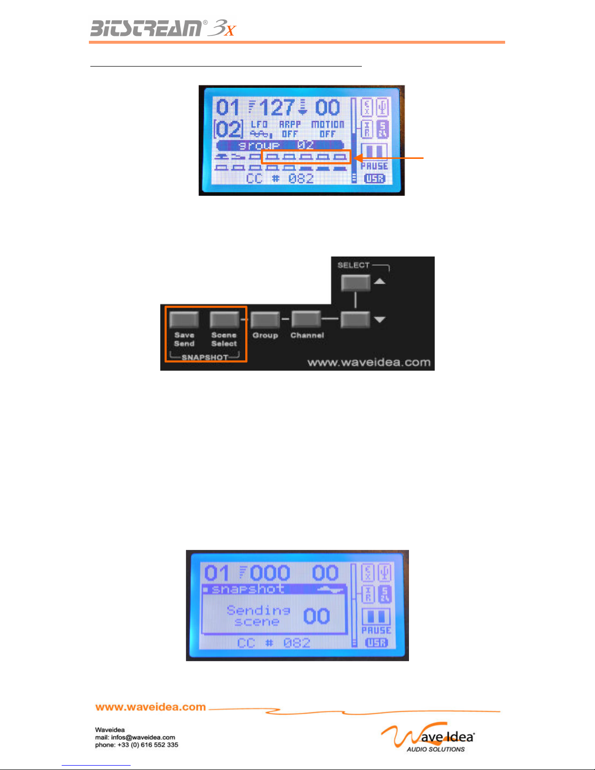
USER MANUAL
Screen dedicated to the transport buttons used as standard buttons
Scene Memories
Goal
This function allows the saving/restoring of the current value of each slider and button.
This function is very useful during a live show. The Bitstream 3X has 100 scene memories, the values
of all the controls are saved/restored in one of these 100 scene memories according to the number
selected.
All the parameters are saved in a non volatile memory that permits it to be retrieved after having turned
off the Bitstream 3X.
Restitution of scenes
A quick tap of the « Save/Send » button allows the scene to be sent to MIDI Out 1 and USB Out 1, the
position of all the buttons and sliders being saved previously. The scene memory rendered
corresponds to the scene number selected.
Rev 1.1 - Page 35
Transport bar used
as standard buttons
Page 36
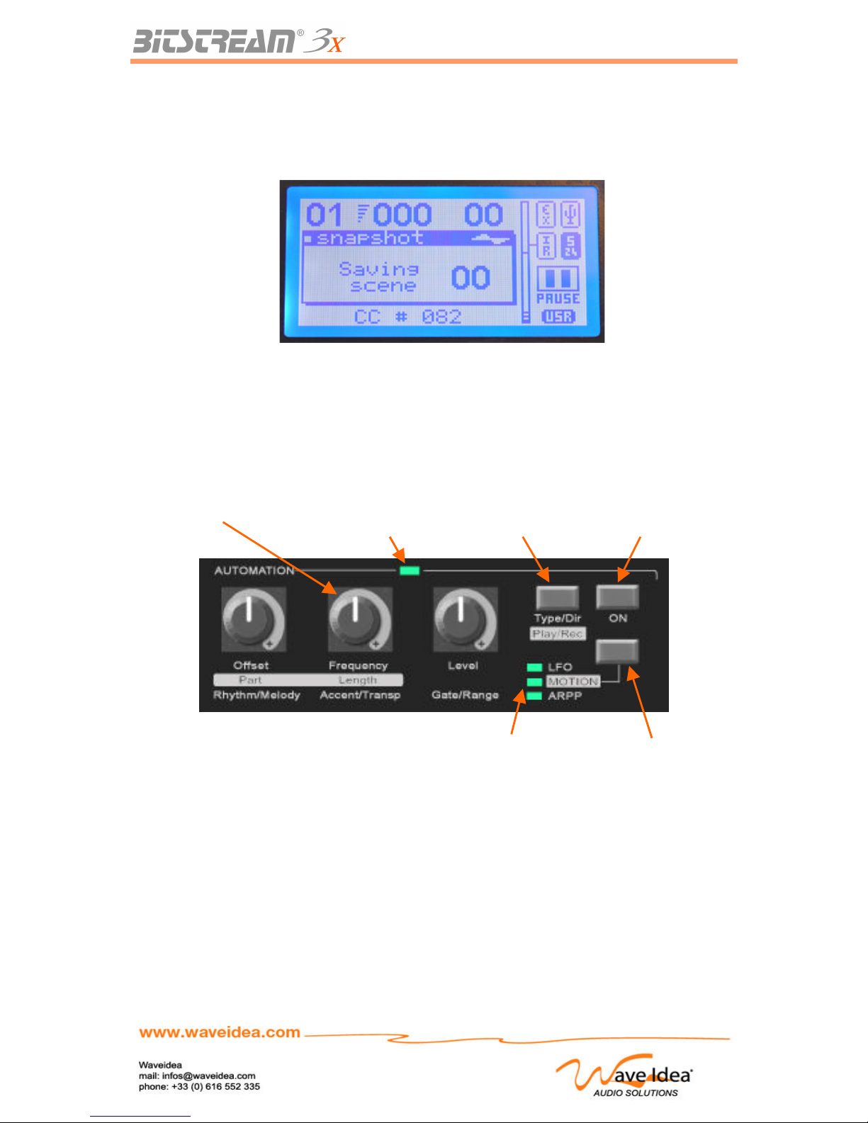
USER MANUAL
Saving the scenes
Pressing and holding the « Save/Send » button for longer than 3 seconds will save the coordinates of
all the buttons and sliders for the scene number selected.
Note 1: The 100 scene memories of the Bitstream 3X are accessible via the up-down or encoder
button, when the scene function is selected.
Automations
Knobs and buttons associated with the automations
Three knobs, three buttons and four LED (Light Emitting Diode) are dedicated to automations. The
printed words on the face of the Bitstream 3X allows the user to find the different functions controlled
by each button and slider.
The Selection Button allows the user to choose the control of one of the three automations, each
automation has a dedicated LED Selection, and so the user can quickly see which automation is
currently selected.
Simply pressing the Selection button allows the user to change from one automation to another.
The General Automation LED will be lit when at least one automation is activated, it will be off if none
of the three automations are activated.
The On/Off Button Turns on and off the automation selected.
Rev 1.1 - Page 36
3 dedicated knobs Automation
light (LED)
Button for
parameter #1
Stop/Go
Button
Selection
Button
Selection
Lights (LED)
Page 37
USER MANUAL
The three dedicated potentiometers for the automations still function in hook mode, and no « value
jumping » will occur.
It is possible that once the user selects a new automation, the physical position of one of the knobs will
not correspond to the value of the parameter anymore; the user should then put the knob back into the
position of the previous value in order to avoid unwanted jumps.
For more information concerning Hook Mode, refer to the dedicated chapter.
Functions of the controls associated with automations
The table below summarizes the functions associated to the three knobs as well as the automation
parameter button, depending on the current function selected.
Note that the SHIFT key can be used to access the different parameters (changing the value of a knob
or button while holding the SHIFT)
Pot. 1 Pot. 2 Pot. 3 Button #1
LFO Offset Frequency Amplitude Waveform
LFO + SHIFT key Offset Frequency Amplitude Waveform
Arppeggiator Rhythm Accent Gate Direction
Arppeggiator + SHIFT key Melody Transpose Range Synch mode
Motion Sampler Part Lenght - Play part
Motion Sampler
+ SHIFT key
Part Lenght - Record part
Waveforms Generator: Low Frequency Oscillator
Goal
The LFO (Waveforms Generator) allows the generation of a Waveform in different shapes: sine, square,
triangular or random.
This wave can be considered like a slider or knob, and therefore introduced in any MIDI chain defined by the
user. This functionality of the Bitstream 3X gives the user a MIDI control without having to manually and
continually modify a slider.
Each of these 4 Waveforms can be controlled as far as amplitude, offset and frequency, which offers a large
flexibility in configuration of the parameter to control.
Selection of the Waveform
The LFO can generate the following waveforms:
- Sine
- Square
- Triangle
- Random
All these waveforms can be adjusted in amplitude, frequency and offset, with the help of the 3
dedicated knobs
The button #1 allows selecting one of these waveforms, which will be displayed on the LCD.
Changing the waveform is performed in real-time, as soon as the user press on the dedicated button
For instance, using the sine waveform on a volume control will have for effet to create an amplitude
modulation, using the random waveform allows to insert into the assigned LFO MIDI event any random
value, that can be useful to create a continuous modification of a parameter, randomly.
Output Amplitude
A knob is dedicated to regulate the amplitude of the generated waveform. It allows the user to vary it
from 0 to 63 and can be adjusted at any time.
Rev 1.1 - Page 37
Page 38
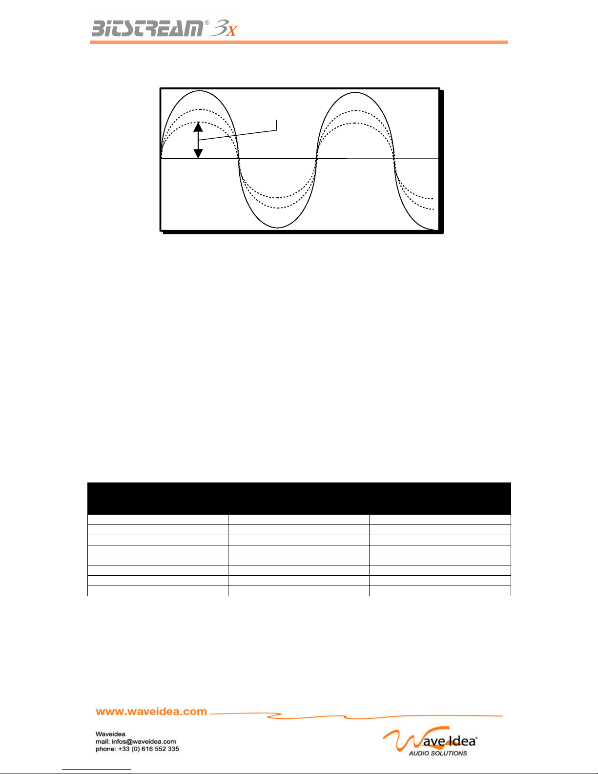
USER MANUAL
The following graph shows the Waveform sine being regulated, when the slider « Offset » is in an
intermediary position (Offset = 64)
If the amplitude generated by the LFO is greater than 127, it will be automatically « saturated » to 127.
In the same way, if it is less than 0 it will be forced to 0.
Adjustment of the frequency and synchronization
The LFO, like each of the 3 automation functions (LFO, arppeggiator, Motion Sampler), has its own
method of synchronization, independent of the other automations.
The LFO can therefore be synchronized on an internal time basis, generated by the Bitstream 3X, or
by the external MIDI clock on the MIDI In or USB In port.
The LFO and other automation functions have 3 modes of synchronization:
- Internal Synchronization, dependant on the BPM generated by the Bitstream 3X
- External Synchronization, dependant on the clock received on MIDI In
- External Synchronization, dependant on the clock received on USB In
Once the method of synchronization is chosen, via the menus of the Bitstream 3X, the user can adjust
the frequency of the LFO via a knob called « Frequency », in real time.
The slider covers 8 frequencies of synchronization for the LFO, described on the table below:
Synchronization of the LFO from the internal or external MIDI clock
SYNCHRONISATION : INTERNAL / EXTERNAL OF THE LFO (24 ppqn)
Mode Description Example @ 120 BPM - 4/4
INT/EXT 0 1/64 period / measure tbd Hz
INT/EXT 1 1/32 period / measure tdb Hz
INT/EXT 2 1/16 period / measure tbd Hz
INT/EXT 3 1/8 period / measure tbd Hz
INT/EXT 4 ¼ period / measure tbd Hz
INT/EXT 5 ½ period / measure tbd Hz
INT/EXT 6 1 period / measure tbd Hz
INT/EXT 7 1 sample at each clock tbd Hz
The value of the frequency of the Waveform generated depends on the value of the knob, as well as
the value of the BPM of the MIDI clock, which is received or generated by the Bitstream 3X.
Rev 1.1 - Page 38
127
Offset = 64
0
0<Amplitude<64
Page 39
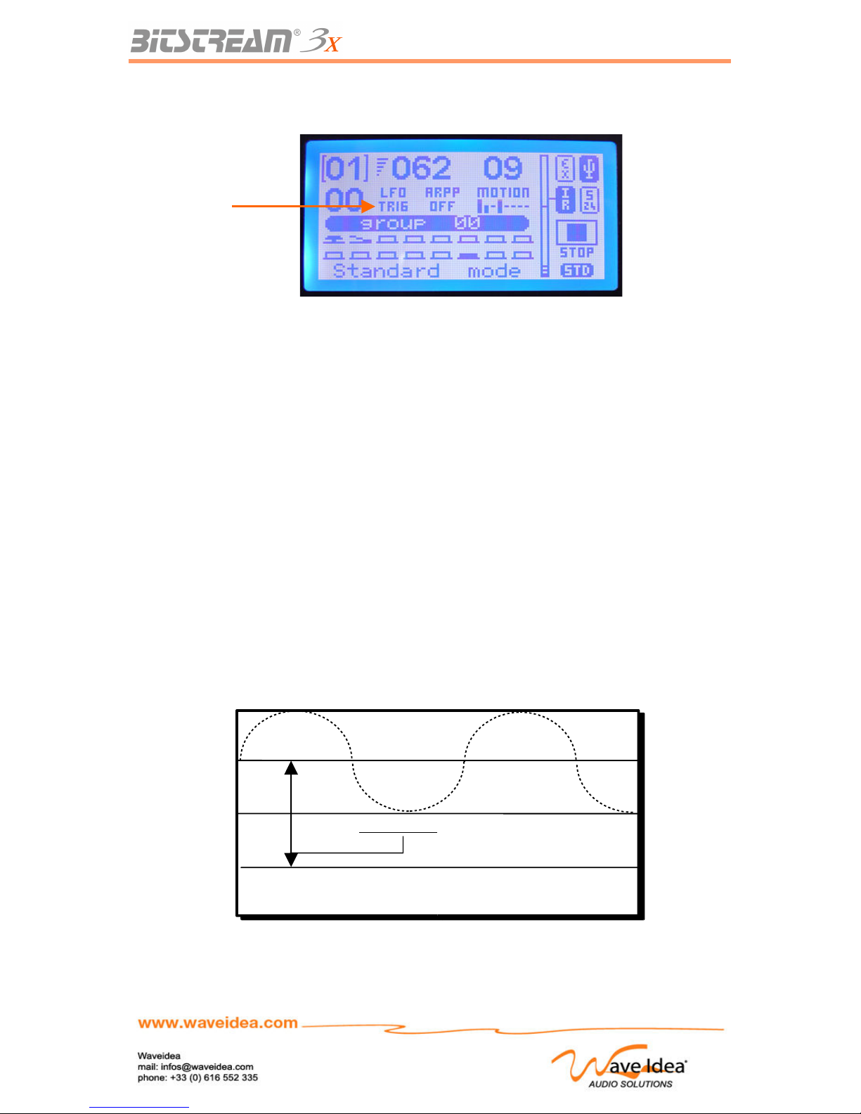
USER MANUAL
Once the LFO is externally synchronized, if the incoming MIDI clock is not detected, or if the message:
START MIDI is not received or generated, the Bitstream 3X will show:
Note 1: Once the LFO is externally synchronized on one of the two entry points, MIDI or USB, the LFO
will start if the signal: MIDI START or MIDI CONTINUE is received.
Note 2: Once the LFO is externally synchronized on one of the two entry points, MIDI or USB, the LFO
will stop if the signal: MIDI STOP is received. The TRIG screen will disappear and the Waveform will
appear as its being generated.
Note 3: Once the LFO is internally synchronized with the MIDI clock generated by the Bitstream 3X,
pressing START on the Transport Bar will start the LFO. In this case the menus should be configured
so that the Bitstream 3X generates the signals of internal synchronization.
Note 4: Once the LFO is internally synchronized with the MIDI clock generated by the Bitstream 3X,
pressing STOP on the transport bar will stop the LFO. . In this case the menus should be configured
so that the Bitstream 3X generates the signals of internal synchronization.
Note 5: For more information concerning the internal synchronization of the transport bar, refer to the
applicable chapter.
Adjustment of the offset value
A knob is dedicated to regulate the Offset (mean value) of the generated waveform. It allows the user
to vary it from 31 to 95, and can be adjusted at any time.
The following graph shows how to regulate the Offset on a sine waveform.
Rev 1.1 - Page 39
127
Offset = 95
Offset = 64
Offset = 31
0
31 < Offset < 95
LFO not
trigged
Page 40
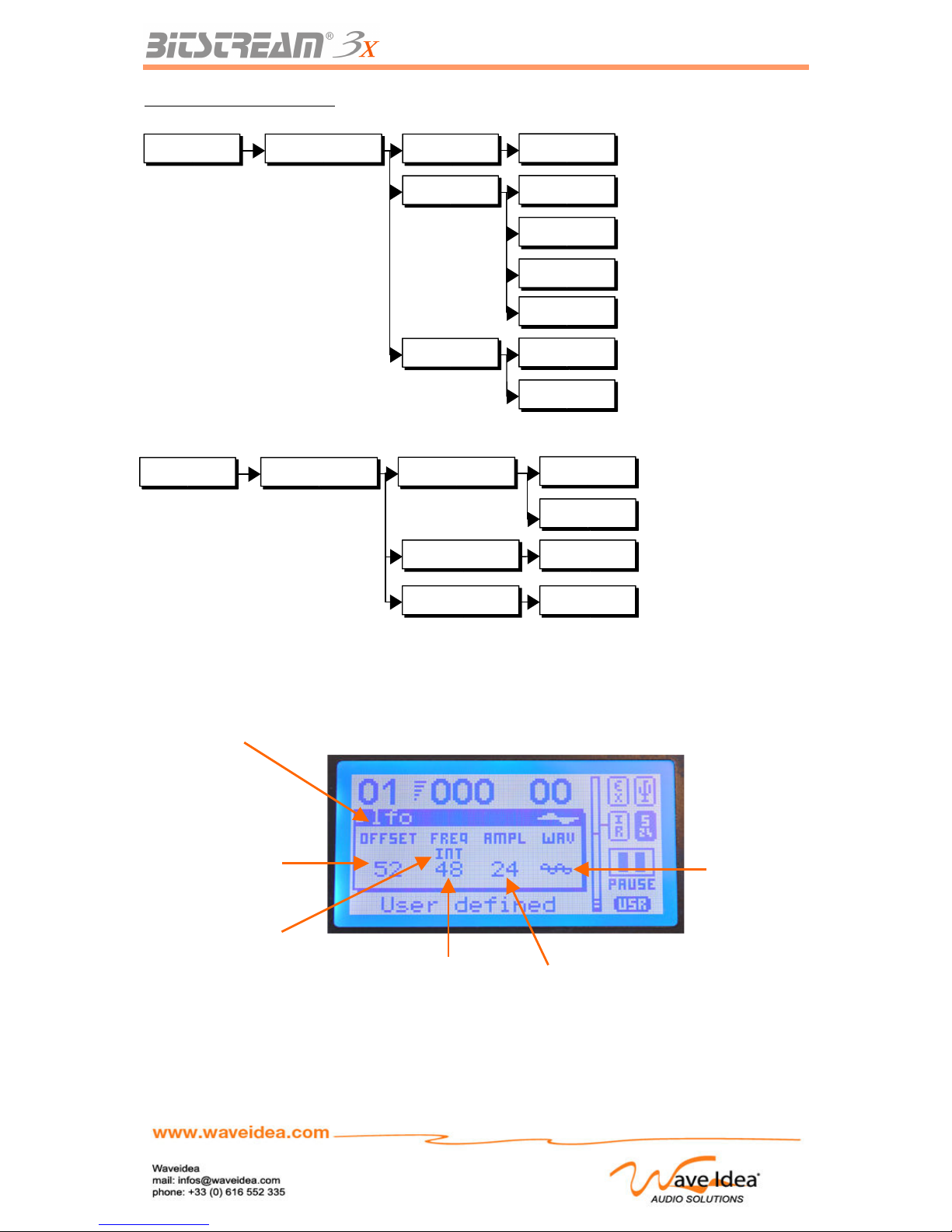
USER MANUAL
Menus associated to the LFO
Note 6: The other parameters associated to the LFO (Amplitude, frequency …) being directly
accessible via the dedicated sliders, were not therefore included in the menus of the Bitstream 3X
Note 7 : The value generated by the LFO is not shown in the LCD value field, the LFO value is
represented by a small bar graph which gives and idea of the progress of the Waveform.
Rev 1.1 - Page 40
Zone incrustation
LFO
Median Value
(Offset)
Value of the
frequency
Method of
synchronization
Int / Ext
Value of the
amplitude
Generated
Waveform
Automations Low Freq Osc LFO State
Waveform
Square
Stop/Go LFO
Waveform generated
On/Off
Sine
Triangle
Random
Waveform generated
Waveform generated
Waveform generated
LFO Sync
Internal
External
LFO internally synchronized
LFO externally synchronized
Midi config Realtime config
30 - 250
USB In
MIDI In
External src
Internal tempo
Internal state On/Off
Tempo (BPM) internal synchro
Stop/Go internal synchro
Choice of MIDI entry MIDI for the
synchronizable functions from an
external clock
Page 41

USER MANUAL
Arppeggiator
Goal
The arppeggiator is definitely one of the most advanced functions of the Bitstream 3X.
More than a standard arppeggiator, it can be considered as a generator of predefined rhythms, where
the users will have access to every detail of the generation of the Notes.
The Bitstream 3X is therefore capable of generating MIDI Notes, having the motifs organized in banks,
valid for different types of music.
Once the arppeggiator is running, the Bitstream 3X is connected to an external expander (software or
hardware) capable of playing the MIDI notes received, the arppeggiator can be allocated to a MIDI
track to automatically enrich the piece played.
All the parameters of the arppeggiator are accessible in real time, so that the user can evolve the
generated rhythms easily. The arppeggiator can be allocated to a rhythmic track or a synthesized
track, with surprising results.
The different parameters of the arppeggiator and their usage are described in the following pages.
Rhythm
The RHYTHM parameter allows the user to select the rhythm model of the generated sequence. The
Bitstream 3X has as in it’s default settings a library of 128 rhythm models per bank, with 4 style banks:
MASTER, HOUSE, BREAKS and LATIN. These banks are accessible via the menu described at the
end of this chapter.
The models are classified by decreasing density. The first values correspond to very thick motifs and
the last values give rhythms much more pure. If the rhythm has a value of "0", a note is generated for
each step of the resolution (see RESOLUTION).
All the rhythmic models as well as the accents (see below) were captured by musicians playing,
(drummers, percussionists, programmers) to maintain the natural and authentic element of the
different styles of music.
Note: The parameter RHYTHM is accessible directly via the automation knob 1, without pressing the
SHIFT key.
Accent
At the installation of the rhythm, the user can choose an accent model for the sequence generated.
The accent acts on the velocity of the notes, and is imperceptible, unless the sound used by the
arppeggiator is sensitive to velocity. If the accent has a value of "0", no note is accentuated, and all the
notes in the sequence will be played with the same velocity. If the value is not 0, the notes accented by
the current accent model will be played at a faster velocity.
The quantity of the effect of the accent, meaning, the difference between the velocity of the accented
and non accented notes is regulated by the parameter VELOCITY (see below)
Note: The ACCENT parameter is accessible directly via the automation knob 2, without pressing the
SHIFT key.
Gate
This parameter acts on the length of the notes. The smaller values allow you to hear only the attack of
the sound, whereas the larger numbers give the note legato.
Rev 1.1 - Page 41
Page 42

USER MANUAL
Note: The GATE parameter is accessible directly via the automation knob 3, without pressing the
SHIFT key.
Melody
MELODY defines the ensemble of the notes used in the sequence. It selects a particular motif from a
library of arpeggio rhythms, triads, and scales, as well as more complex phrases.
These motifs can vary infinitely thanks to the RANGE parameters (see below) and DIRECTION
parameters, in order to adapt to the even most creative styles of music.
Note: The MELODY parameter is accessible directly via the automation knob 1, by PRESSING the
SHIFT key.
Transpose
This parameter obviously allows the user to transpose the sequence. The value shown is numbered in
half-tones. If the arppeggiator plays percussion sounds, (on the MIDI channel 10 in general),
TRANSPOSE serve to select the desired instrument (see RANGE).
Note: The TRANSPOSE parameter is accessible directly via the automation knob 2, by PRESSING
the SHIFT key
Range
The RANGE is the number of notes that the sequence uses among those of the motif defined by
MELODY. If the RANGE value is "1", the sequence will only play the first note of the motif. This
parameter is very useful to refine an arpeggio rhythm or to model a bass line.
In the case of percussion sounds, RANGE decides from the number of instruments played by the
sequence.
Note: The RANGE parameter is accessible directly via the automation knob 3, by PRESSING the
SHIFT key
Resolution
The RESOLUTION corresponds to the number of notes uniformly spitted in a measure which will be
the base of the sequence. This value is a maximum, the real number of notes played in a measure
depends on the RHYTHM parameter.
The Bitstream 3X integrates 6 possible values of resolution:
• 4th or "Quarter" corresponds to the quarter note, 4 notes per measure.
• 8th corresponds to the eight note, 8 notes per measure.
• 16th corresponds to the sixteenth note, 16 notes per measure.
• 32th corresponds to the thirty-second note, 32 notes per measure.
• 8-trip or "Eighth tripled" when there are 12 notes per measure.
• 16-trip or "Sixteenth tripled" when there are 24 notes per measure.
Note: The RESOLUTION parameter is only accessible from the menus of the Bitstream 3X
Direction
The DIRECTION is the order in which the notes in the sequence are played. For example, if the
sequence plays a simple motif like a scale or triad, (see MELODY), "UP" signifies from the low register
(grave) towards the high pitched, "DOWN" the high towards low, "UP – DOWN" round trip starting with
the grave. "RANDOM" plays notes obviously in a random order.
Rev 1.1 - Page 42
Page 43

USER MANUAL
In the case of a more complex motif, the DIRECTION still corresponds to the playing order of the notes
in the ensemble of the notes defined by MELODY.
We have added declines to the Random mode : "CUSTOM 1" plays by alternating the first note with a
random note from the motif, and "CUSTOM 2" forces the first note of the motif on the accents given by
ACCENT.
Note: The DIRECTION parameter is accessible directly via the button of the automation parameter 1,
without pressing SHIFT
Modes and synchronization
The Bitstream 3X has 4 different modes of synchronization and of launching the arppeggiator:
• "NORMAL" : the sequence starts once the Bitstream 3X receives the information NOTE ON on
the channel of the arppeggiator (for example pressing the keys from an external keyboard),
and it stops when it receive the message NOTE OFF (for example a light touch on the
keyboard). The sequence takes into account the pitch and the velocity of the note received.
• “HOLD”: Like "NORMAL", but without NOTE OFF. The arppeggiator plays continually the
sequences based on the information (pitch and velocity) received in real time.
• "AUTO-TRIG»: The sequence starts when the Bitstream 3X receives the information from
MIDI START on the channel of the arppeggiator (for example coming from a rhythm box, a
computer or an external sequencer). The sequence generated is based on a default pitch and
velocity. The pitch is modifiable through the parameter TRANSPOSE.
This mode can also be used to make the arppeggiator completely autonomous, without having
to use an external machine for the synchronization.
In this case, the parameter « real-time internal » available through the menus should have the
status « on » so the Bitstream 3X generates it’s own MIDI clock, also redirected towards the
arppeggiator.
• "KEYBOARD»: This mode is similar to "NORMAL" concerning the stopping of the sequences.
However, the notes used are no longer those defined by the parameter MELODY, but those of
the different NOTES ON received in entry. Also, in the case where the MIDI keyboard is
connected to the Bitstream 3X, this mode allows the generation, in real time, of sequences of
notes played on the keyboard.
The arppeggiator, like each of the three functions of automation (LFO, arppeggiator, Motion Sampler),
has its own method of real time synchronization, independent of the other automations.
The arppeggiator can be synchronized based on internal time, generated by the Bitstream 3X, or from
a MIDI clock on the MIDI In or USB In port.
Also the arppeggiator and other automation functions have three modes of synchronization:
- Internal Synchronization, dependant of the BPM generated by the Bitstream 3X
- External Synchronization, dependant of the MIDI In clock
- External Synchronization, dependant of the USB In clock
Once the method of synchronization is chosen via the menus of the Bitstream 3X, the user can choose
one of the 4 modes of synchronization for the arppeggiator, depending on the MIDI environment.
Note 1: The parameter MODE is accessible directly via the automation parameter 1 button, by
pressing SHIFT
Note 2: Once the arppeggiator is synchronized externally by one of the two entries: MIDI or USB, a
MIDI START or MIDI CONTINUE signal will start the arppeggiator.
Rev 1.1 - Page 43
Page 44

USER MANUAL
Note 3: Once the arppeggiator is synchronized externally by one of the two entries: MIDI or USB, a
MIDI STOP signal will stop the arppeggiator
Note 4: Once the arppeggiator is synchronized internally on the MIDI clock generated by the Bitstream
3X, pressing START on the Transport bar will start the arppeggiator. In this case, the menus should be
configured so that the Bitstream 3X generates the signals of internal synchronization.
Note 5: Once the arppeggiator is internally synchronized on the MIDI clock generated by the Bitstream
3X, pressing STOP on the Transport bar will stop the arppeggiator. In this case, the menus should be
configured so that the Bitstream 3X generates the signals of internal synchronization.
Note 6: For more information about the internal synchronization of the Transport bar, see the dedicated
chapter.
Note 7 : The arppeggiator can be synchronised, for example on the MIDI clock on the USB port, and
the notes will be set off by the notes received on the MIDI In entry, the two parameters being
independent, and accessible via the menus of the Bitstream 3X.
Velocity
The parameter VELOCITY adjusts the quantity of the effect of the accent. It acts directly on the
difference between the velocity on the accented and non accented notes. The default value is "64".
To hear the effect of this parameter, the sound used by the arppeggiator has to be sensitive to velocity.
Note: The parameter VELOCITY IS accessible only from the menus of the Bitstream 3X
Swing
SWING allows the user to insert some delays before or after odd numbered notes. Its values go from
"–63" to "+64", with "0" by default. The goal is to add groove to a binary pattern in order to converge to
a triple-beat or hybrid pattern.
For example, with a resolution of "16th", a SWING positioned on the triple will shift the second and
fourth notes towards a trio of eight-notes, making the groove sound often found in Hip-Hop, Jungle,
Jazz, etc.…
Note: The parameter SWING is accessible only from the menus of the Bitstream 3X
Offset
OFFSET allows the setting-off of the notes generated by the arppeggiator in time. The resolution of the
set-off is a MIDI tick. With this parameter, the user can generate the first note of the arpeggio set-off by
the note source, for example, in counter time to create new rhythms.
Note: The parameter OFFSET is accessible only from the menus of the Bitstream 3X
Channel
This parameter is the MIDI channel on which the arppeggiator will play following the received notes.
Note that all the notes received on a different MIDI channel will not generate arpeggios.
The MIDI notes generated are equally play on this MIDI channel.
Also, this CHANNEL parameter is therefore the channel on which the arpeggios are generated and
set-off.
Note: The parameter CHANNEL is accessible only from the menus of the Bitstream 3X
Rev 1.1 - Page 44
Page 45
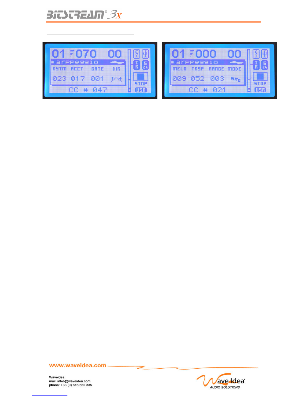
USER MANUAL
Screens associated with the arppeggiator
Rev 1.1 - Page 45
Arpeggiator screen without pressing SHIFT
Arpeggiator screen while pressing SHIFT
Page 46
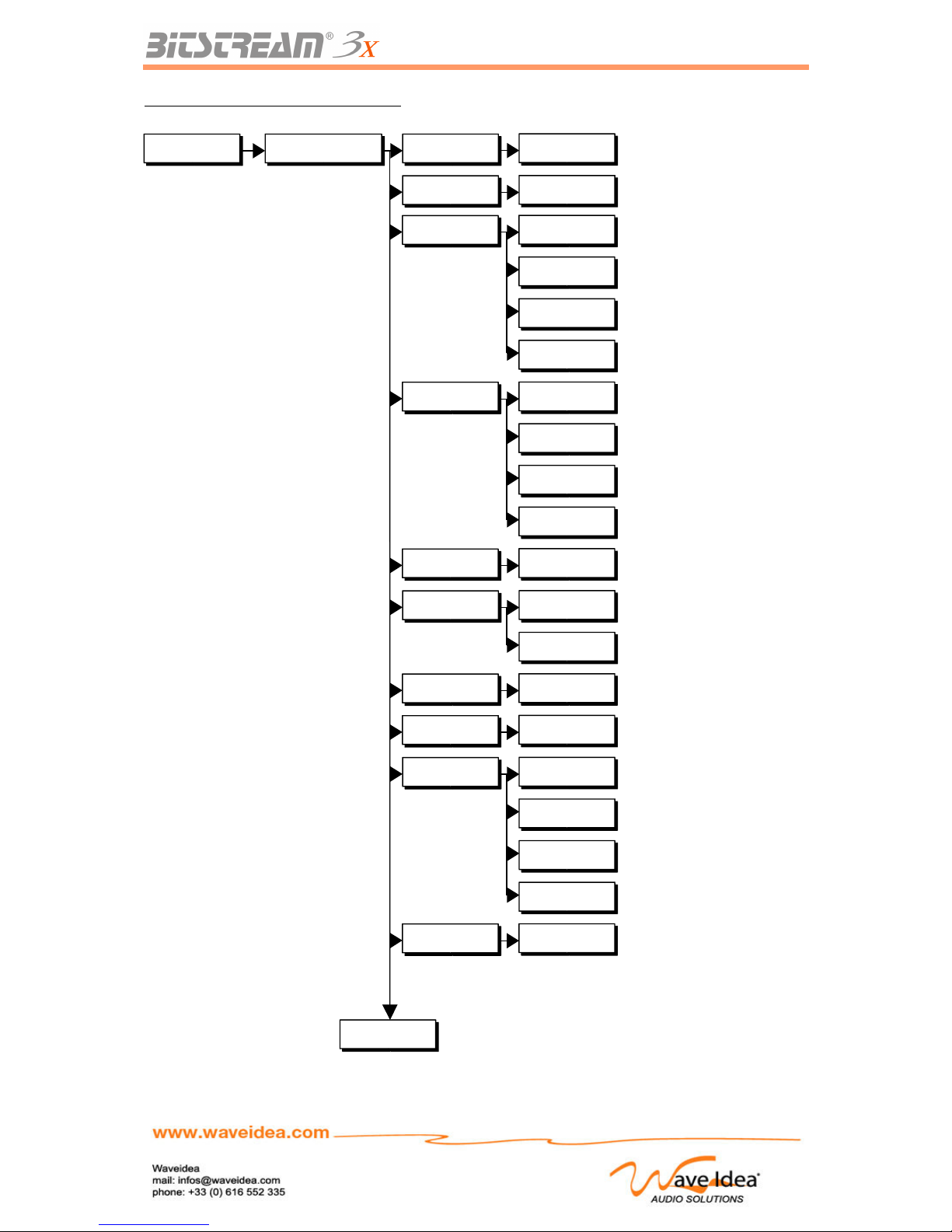
USER MANUAL
Menus associated with the arppeggiator
Rev 1.1 - Page 46
Automations Arppeggiator Arpp State
Arp Offset Offset Value (0-47)
On/Off
0-47
Accent Bnk
Master
Techno
Breaks
Latin
Master Accent Bank
Techno/House Accent Bank
Break-beats Accent Bank
Latin Accent Bank
Rythm Bnk
Master
Techno
Breaks
Latin
Master Rhythm Bank
Techno/House Rhythm Bank
Break-beats Rhythm Bank
Latin Rhythm Bank
Melody Bnk
Master
Master Melodies Bank
Clock reso
4-64 th
8-16 trips
Clock Resolution Selection
Clock Resolution Selection
Arpp Swing
0-127
Swing Value
Arp velocity
0-127
Velocity Value
Arpp mode
Auto-trig
Normal
keyboard
Hold
Automatic Synchro Mode
Arpeggiator Synchro Mode
Keyboard Synchro Mode
Hold Synchro Mode
Arp channel
1-16
MIDI channel Value
Continued
Page 47
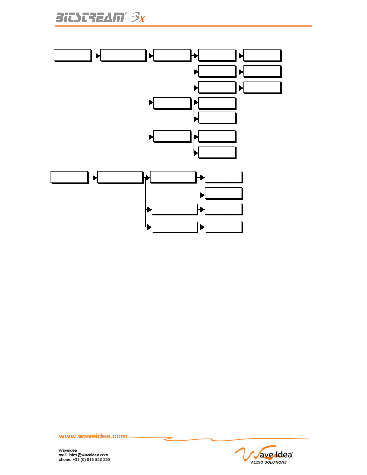
USER MANUAL
Menus associated with the arppeggiator (continued)
Motion Sampler
Goal
As the name indicates, the motion sampler allows the saving and restitution of the movements of the
controls of the Bitstream 3X, in real time.
The user can automate certain motions of the sliders and other controls, in order to have two hands
free to use other controls or functions of the Bitstream 3X.
The motion sampler is part of the currently selected group during the restitution phase, for example, a
slider recorded while group 1 is selected, and restituted while group 2 is the new group selected, will
generate the MIDI events of the slider assigned to group 2 (the group selected during the restitution).
The motion sampler can optionally be configured by the menus in Loop mode, which will allow the
looping of the tracks during the restitution, no matter what the length of the previously saved track.
The characteristics of the motion sampler are as follows:
- Possible sampling of all controls of the Bitstream 3X (sliders, infrared, joystick, buttons...)
- 8 sample tracks – 1 control per track
- Possible restitution of the 8 tracks simultaneously
- Controllable length of ½, 1, 1 ½, 2, 2 ½, 3, 3 ½, 4 measure(s) independently for each track
- Synchronization of external or internal MIDI
- Looping of the tracks for continuity
- Graphical display of the value of each track
- Sampler frequency : Each three MIDI clock ticks for an increased fluidity
- Saving of each track in a non volatile memory
Rev 1.1 - Page 47
Midi config Realtime config
30 - 250
USB In
MIDI In
External src
Internal tempo
Internal state On/Off
Tempo (BPM) internal synchro
Stop/Go Internal Synchro
Choice of MIDI entry for the
synchronizable functions
From an external clock
Automations Arppeggiator Arp outputs MIDI Out 1
MIDI Out 1
On/Off
MIDI Out 2
MIDI Out 2
On/Off
USB Out 1/2
USB Out
On/Off
Arp Midi src MIDI Inis directed towards the arpp.
MIDI In
USB In
USB In is directed towards the arpp.
Arp sync Internal Synchro for the arpp.
Internal
External External Synchro for the arpp.
Page 48
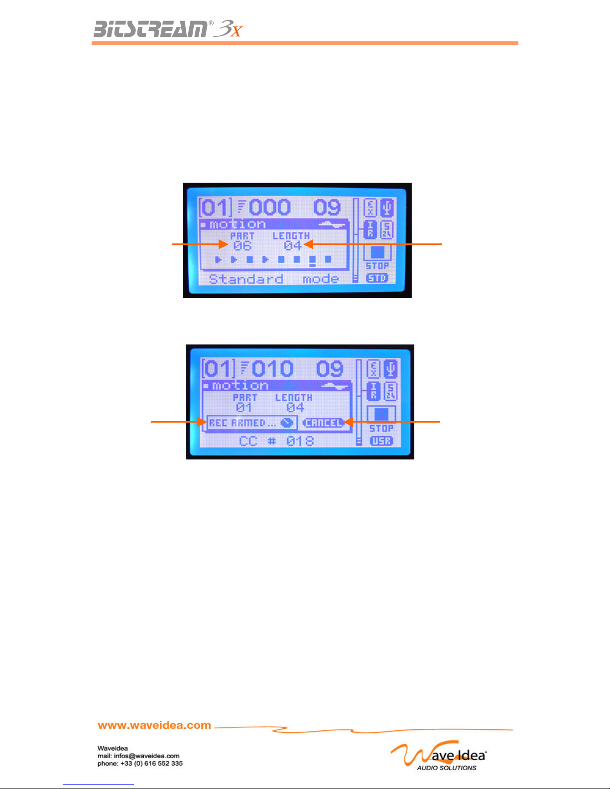
USER MANUAL
The saving and restitution of the motions can be done in real time, without stopping the other functions
of the Bitstream 3X.
The On/Off automations button allows for the complete arrest of the motion sampler, all the currently
selected tracks will be immediately stopped.
Recording a Sequence
Recording a sequence involves the following simple (automation « motion » selected):
1- Chose the track to be recorded (regulated by the automation knob 1)
2- Start the sequence to be recorded (Press simultaneously the automation button and SHIFT)
3- Choose the length of the recording (regulated by the automation knob 2)
4- Start the recording by changing the value of the control to sample
5- Save the movements in the memory
The user decides on which track he wants to record the new sequence (step one) by the automation
slider 1. Once this track is selected, the user prepares the recording by pressing automation button 1
and the SHIFT key at the same time (step two), the dedicated screen is displayed on the LCD, the user
can then modify the length of the recording by using automation slider 2 (step 3).
The Sampler waits until the user changes the values of the Bitstream 3X control to be sampled before
starting the recording.
Rev 1.1 - Page 48
Track
selected
Length of the
Track (in
measures)
Cancel
To cancel
recording
Recording
armed: the
Bitstream 3X
waits for a
change of a
control
Page 49
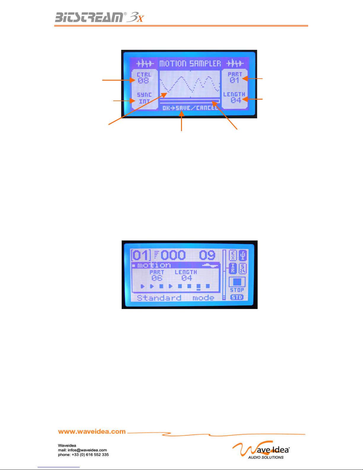
USER MANUAL
Once this phase starts, a dedicated screen allows the visualization of the recorded value:
At the end of the recording, the Bitstream 3X asks if the user wants to save the movements recorded
in the non-volatile memory (the choice is made by choosing OK or CANCEL –step five).
Note 1: If the synchronization of the motion sampler is on internal mode, it is best to verify that the
Bitstream 3X is configured to generate this synchronization, from the menu « midi real-time »
Restitution of a sequence
The restitution of a previously recorded sequence is done very simply, by pressing the automation key
1. It is suggested to follow the following steps (automation « motion » selected):
1- Choose the track to be restituted (regulated by automation knob 1)
2- Start the sequence (press the automation button)
Once the sequence begins, the screen will return to normal and display the values of the different
tracks being restituted.
These different values are updated in real-time and can be visualized on the bar graph.
Rev 1.1 - Page 49
Number of the
control being
sampled
Method of
synchronization of
the sampler
Graphic
Visualisation of
the sequence being
recorded
Contextual Info:
waiting for validation
Progression bar,
corresponding to the
chosen length
Length of the sequence
(in measures)
Number of the track
selected
Page 50
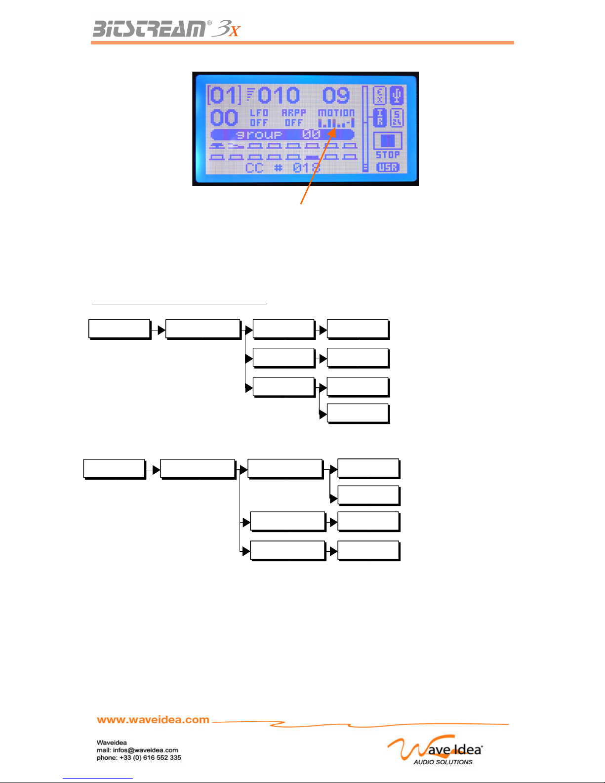
USER MANUAL
Note 1: If the synchronization of the motion sampler is on internal mode, it is best to verify that the
Bitstream 3X is configured to generate this synchronization, from the menu « midi real-time »
Note 2: The parameter « length » is not modifiable except during the recording phase, so it will play
according to the previously decided length of the track.
Menus associated with the motion sampler
Rev 1.1 - Page 50
Midi config Realtime config
30 - 250
USB In
MIDI In
External src
Internal tempo
Internal state On/Off
Tempo (BPM) internal synchro
Stop/Go internal synchro
Choice of MIDI input for the
synchronizable
Function from a external clock
Automations Motion sampler motion state Stop/Go Motion SamplerOn/Off
motion sync Internal Synchro
Internal
External External Synchro
motion loop Restitution in loopOn/Off
Graph of tracks being
restituted
Page 51
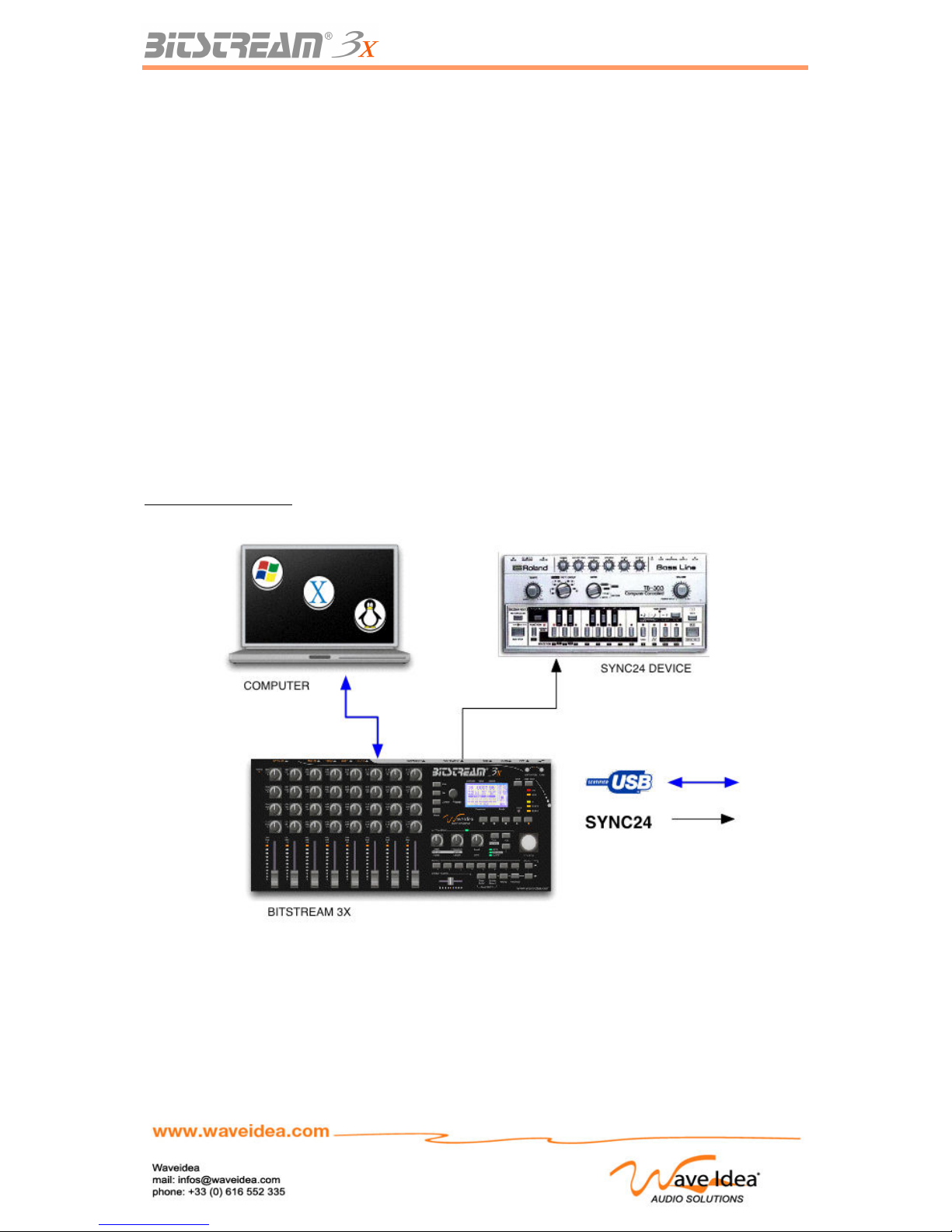
USER MANUAL
SYNC-24 Output
Goal
The protocol SYNC-24 was used on vintage sequencers before the MIDI standard was adopted.
This protocol allows the user to synchronize the old machines such as the Roland TB-303, TR-x0x,
MSQ-700/100, Roland TR-909 and more.
The Bitstream 3X has a SYNC-24 output, compatible with these vintage instruments. This output is
available on the DIN-5 connector, driving the difference electrical signals required by this method of
synchronization.
The Bitstream 3X is capable of generating SYNC-24 signals from real time MIDI messages received
from the different MIDI entries (MIDI In from the connector, MIDI In on USB), therefore, the Bitstream
3X can be considered as a MIDI – SYNC-24 converter, and USB MIDI – SYNC-24 converter.
Note 1: The connection of a SYNC-24 sequencer requires a DIN-5 Male – Male cable, different than a
standard MIDI cable. It can be ordered from Wave Idea.
Note 2: By default, the SYNC-24 output is synchronized by the MIDI In port, whose activity is stopped.
The configuration of the input source and status of the SYNC-24 output are configurable via the menus
of the Bitstream 3X.
Example of connection
Rev 1.1 - Page 51
Page 52
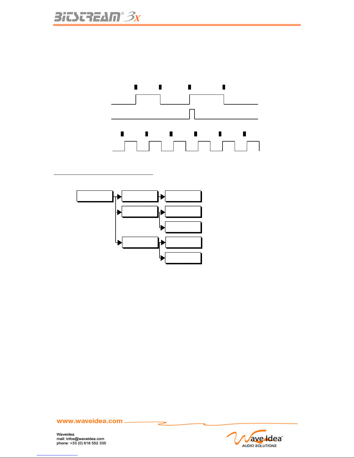
Clock
Clock
Clock
USER MANUAL
Electrical Signals Generated
The different signals generated by the SYNC-24 are grouped into three: Run, Continue and Clock. The
following diagram illustrates the principles of real time MIDI conversion to SYNC-24.
Menus associated to the SYNC-24 output
Navigation of the menus
Principles of navigation
Access to the menus is through the button EDIT; two types of menus are available:
- Menus of configuration (press once)
- Assign Menus (press twice)
Menus of configuration allow the configuration of the parameters of the Bitstream 3X based on the
environment, the functions used or not used, etc.
The Assign Menus allow the user to assign MIDI events and parameters to the Bitstream 3X, the
usage of this menu is described in the dedicated chapter.
To navigate these menus, there are 4 simple and classic functions:
- OK Validation of the current value, or access to a sub-menu
- CANCEL Cancel current function, return from a sub-menu
- UP Increase current value, choose the next menu of the same level
- DOWN Decrease the current value or choose the preceding menu on the same level
Rev 1.1 - Page 52
Clock
Clock
Message MIDI
Sync24 Clock
Start
Stop
Continue
Stop
Message MIDI
Sync24 Run
Sync24 Continue
Sync-24 State On/Off
Source Midi In
USB In
MIDI In to Sync-24 conversion
USB MIDI In to Sync-24 conversion
Sync-24 state
Sync Internal
External
Sync-24 is triggered from internal
Sync-24 is triggered from external
Page 53
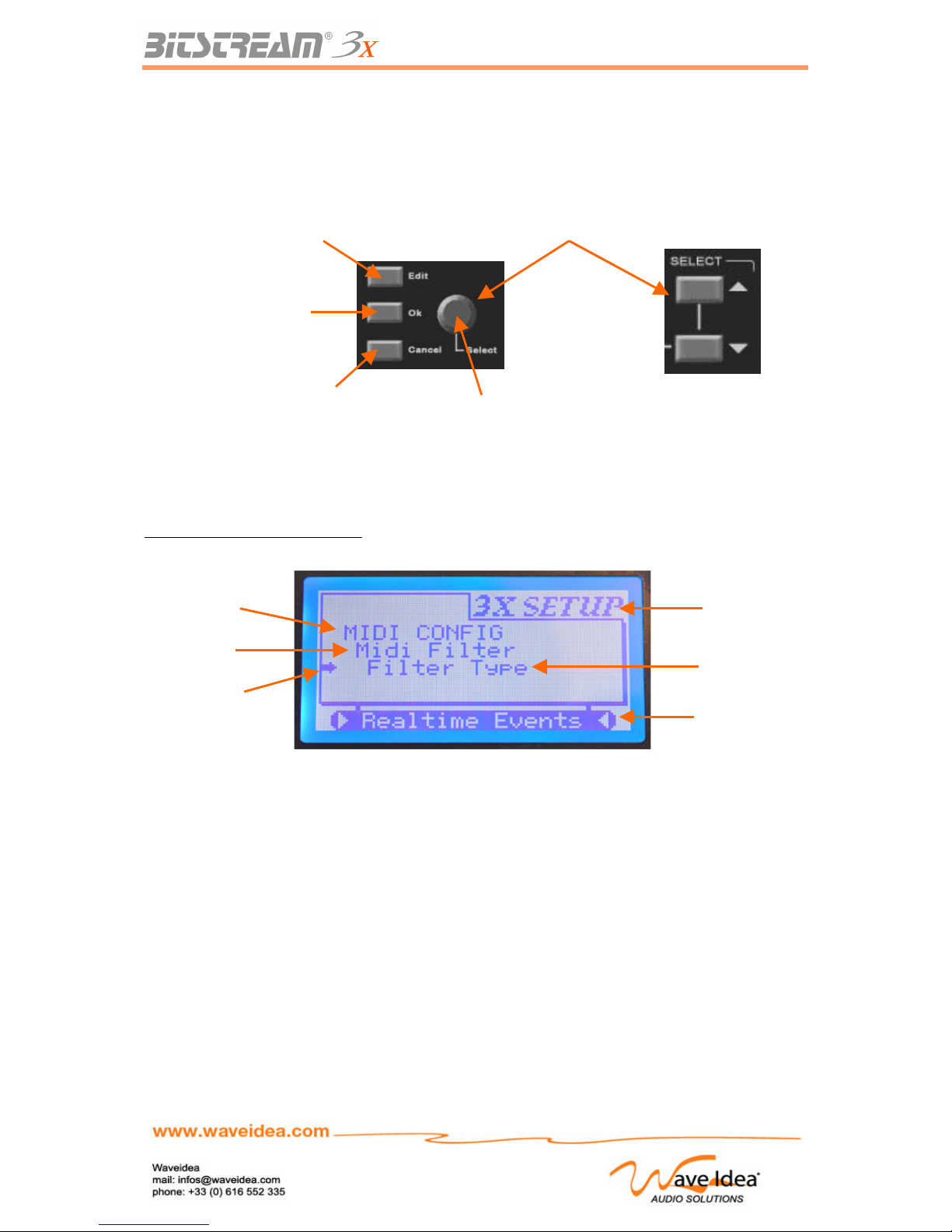
USER MANUAL
The UP – DOWN functions are obtained using the up-down buttons on the face of the Bitstream 3X or,
via the end-less encoder.
The function OK is obtained using the dedicated OK button, or by using the encoder which becomes
the OK button once the Bitstream 3X is in menu mode
To make the menus more readable on the screen of the Bitstream 3X, a graphical method is defined:
Each sub menu is indented on the screen; the different possible values for a menu are at the bottom of
the screen, the presence of a sub-menu is indicated by « >>> » in place of the value of the current
menu.
Example of menu of configuration
Rev 1.1 - Page 53
Access Menus:
Normal->Menus->Assign
Selection
OKButton:
Validation
button OK:
Validation
Cancel button:
Cancel / return
Active Menu
Value of active
Menu or «>>>»
if sub- menu
Menu Mode
Main Menu
Sub-menu
level 1
Sub-menu
Level 2
Page 54
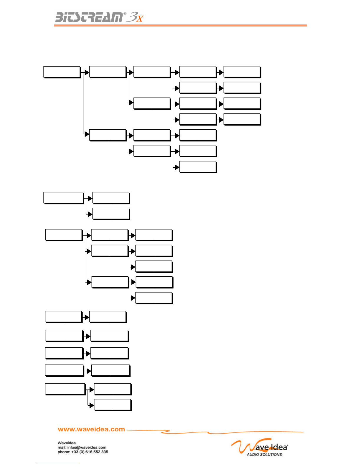
USER MANUAL
Hierarchy of the Menus (Summary)
Rev 1.1 - Page 54
MIDI Config
MIDI Merger Merger Src MIDI In On/Off
USB In On/Off
Merger Dst MIDI Out 1 On/Off
USB Out 1 On/Off
MIDI Filter Filter state
On/Off
Filter type
All events
Realtime
Usage of MIDI In
Usage of USB In
MIDI inputs towards
MIDI Out 1
MIDI inputs USB Out
1
MIDI filter status
MIDI messages are filtered
Real time MIDI messages are filered
Analog mode Jump
Hook
Selection of Jump mode
Selection of Hook mode
Infrared On/Off
On/Off Infrared Controler
Group select 001 - 021
Selection of group
Scene select 000 - 099
Selection of scene number
Midi Channel 001 - 016
Selection of scene number
video mode Normal
Inverted
Selection of video normal mode
Selection of inversed video mode
Sync-24 State On/Off
Source Midi In
USB In
MIDI In to Sync-24 conversion
USB MIDI In to Sync-24 conversion
Sync-24 state
Sync Internal
External
Sync-24 is triggered from internal
Sync-24 is triggered from external
Page 55
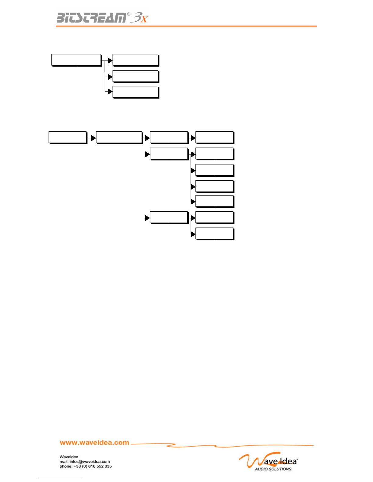
USER MANUAL
Rev 1.1 - Page 55
Automations Low Freq Osc LFO State
Waveform
Square
ON/OFF LFO
Waveform generated : Sine
On/Off
Sine
Triangle
Random
Waveform generated : square
Waveform generated : triangle
Waveform generated : random
LFO Sync
Internal
External
LFO synchronized internally
LFO synchronized externally
Operating mode Standard
User
Selection of standard mode (pre-programmed)
Selection of User mode
Reason Selection of Reason mode
Page 56
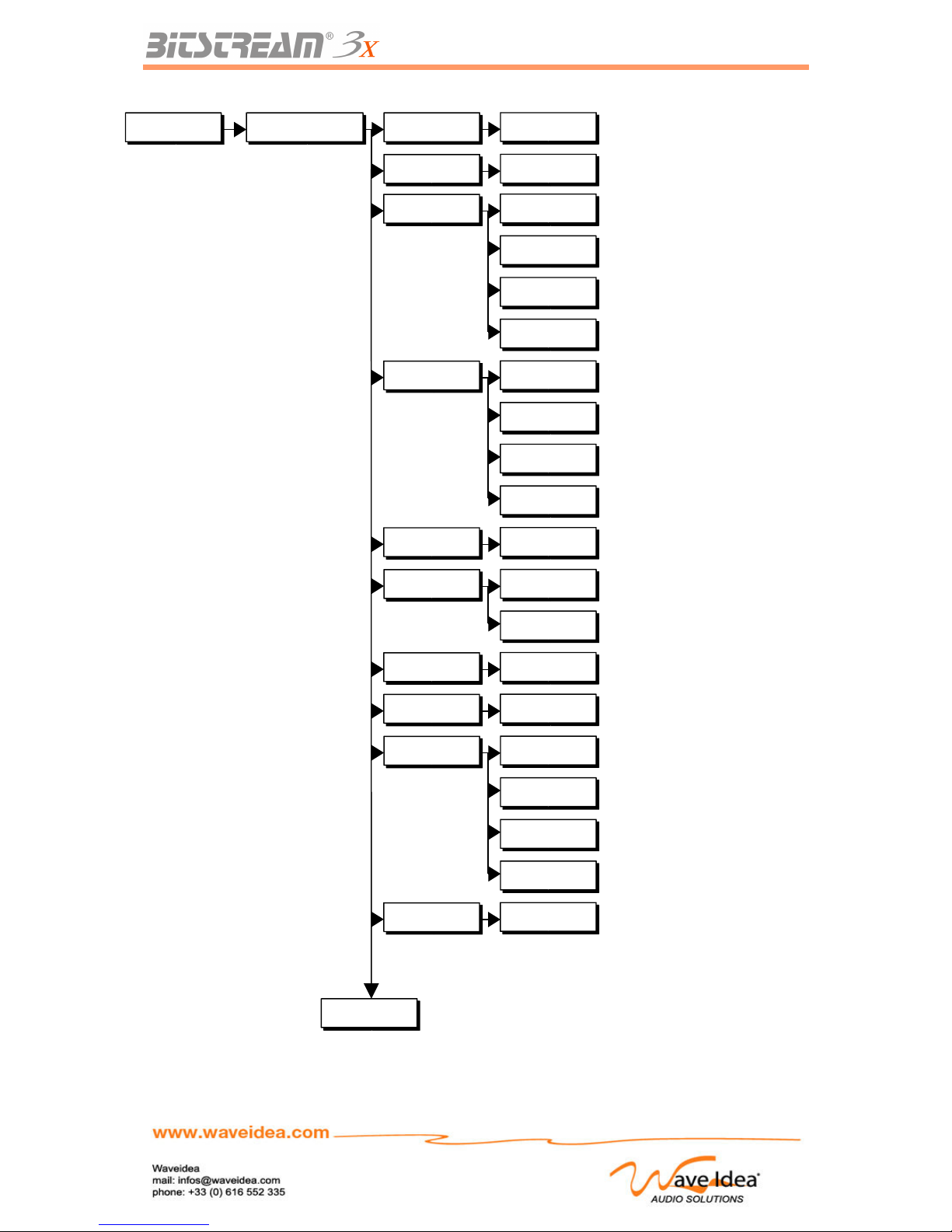
USER MANUAL
Rev 1.1 - Page 56
Automations Arppeggiator Arpp State
Arp Offs Offset Value (0-47)
On/Off
0-47
Accent Bnk
Master
Techno
Breaks
Latin
Master Accent Bank
Techno/House Accent Bank
Break-beats Accent Bank
Latin Accent Bank
Rythm Bnk
Master
Techno
Breaks
Latin
Master Rhythm Bank
Techno/House Rhythm Bank
Break-beats Rhythm Bank
Latin Rhythm Bank
Melody Bnk
Master
Master Melodies Bank
Clock reso
4-64 th
8-16 trips
Clock Resolution Selection
Clock Resolution Selection
Arpp Swing
0-127
Swing Value
Arp velocity
0-127
Velocity Value
Arpp mode
Auto-trig
Normal
keyboard
Hold
Automatic Synchro Mode
Arpeggiator Synchro Mode
Keyboard Synchro Mode
Hold Synchro Mode
Arp channel
1-16
MIDI channel Value
Continued
Page 57
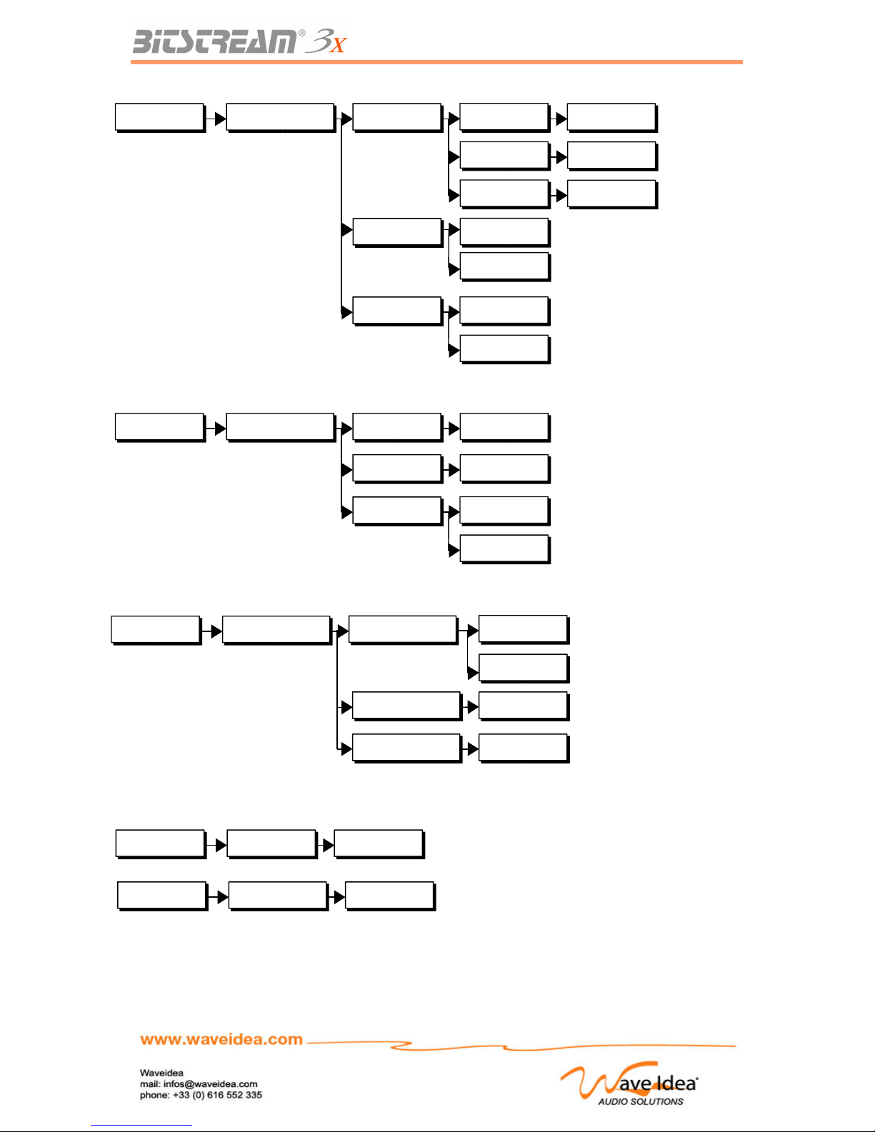
USER MANUAL
Rev 1.1 - Page 57
Automations Arppeggiator Arp outputs MIDI Out 1
MIDI Out 1
On/Off
MIDI Out 2
MIDI Out 2
On/Off
USB Out 1/2
USB Out
On/Off
Arp Midi src MIDI Inis directed towards the arpp.
MIDI In
USB In
USB In is directed towards the arpp.
Arp sync Internal Synchro for the arpp.
Internal
External External Synchro for the arpp.
Midi config Realtime config
30 - 255
USB In
MIDI In
External src
Internal tempo
Internal state On/Off
Tempo (BPM) internal synchro
Stop/Go internal synchro
Choice of MIDI input for the
synchronizable
Function from a external clock
Automations Motion sampler motion state Stop/Go Motion SamplerOn/Off
motion sync Internal Synchro
Internal
External External Synchro
motion loop Restitution in loopOn/Off
Midi config Shift lck Midi On/Off
Enable / disable blocking of MIDI
Midi config Shift lck Chan On/Off
Enable / disable insertion of MIDI
Page 58
USER MANUAL
Other Useful Functions
SHIFT key
The SHIFT key of the Bitstream 3X plays several roles in function of the context the Bitstream 3X is
used.
Blocking MIDI Data
In normal mode, when the user presses SHIFT and thus changes a control of the Bitstream 3X, the
MIDI event is not sent. This allows the user to find, for example the LCD chain and to display it without
having to generate MIDI events.
This blocking of the MIDI data by pressing the SHIFT key, functions just as well with the analog and
digital controls.
This function can also be disabled from firmware V1.3 and higher. A dedicated menu allows to
enable/disable this blocking of MIDI events
Blocking Bitstream 3X MIDI Channel insertion
From firmware V1.4 and higher, the SHIFT button can now be used to prevent the Bitstream 3X from
inserting its own MIDI channel into the assigned MIDI string (when SHIFT button pressed).
This option only concerns the User mode.
In this way, the user can assign a MIDI string featuring a fixed MIDI channel, this fixed MIDI channel
can be overided in realtime by the Bitstream 3X MIDI channel.
Access to supplementary digital controls
In normal mode, the SHIFT key gives access to the 5 assignable multiplexed buttons on the transport
bar. These 5 buttons become 5 digital assignable controls while the SHIFT key is pressed and held.
Note: These 5 supplementary digital controls require the SHIFT key, which cannot block MIDI events
associated with these 5 digital controls.
Increasing the range of value changes
In menus mode, pressing SHIFT during a value change (using the up-down or encoder buttons) allows
the user to increase or decrease the value by 5, instead of by 1, when SHIFT it not held.
Access to multiplexed parameters
In regards to the parameters being changed, the SHIFT key allows the user to access supplementary
multiplexed parameters.
The SHIFT key should be continually held during the access to the supplementary parameters.
Example: The SHIFT key used with the arppeggiator allows access to supplementary parameters
associated with the 3 sliders and buttons dedicated to automations.
For more information concerning this function, see the dedicated chapters
Rev 1.1 - Page 58
Midi config Shift lck Midi On/Off
Enable / disable blocking of MIDI
Midi config Shift lck Chan On/Off
Enable / disable insertion of MIDI
Page 59
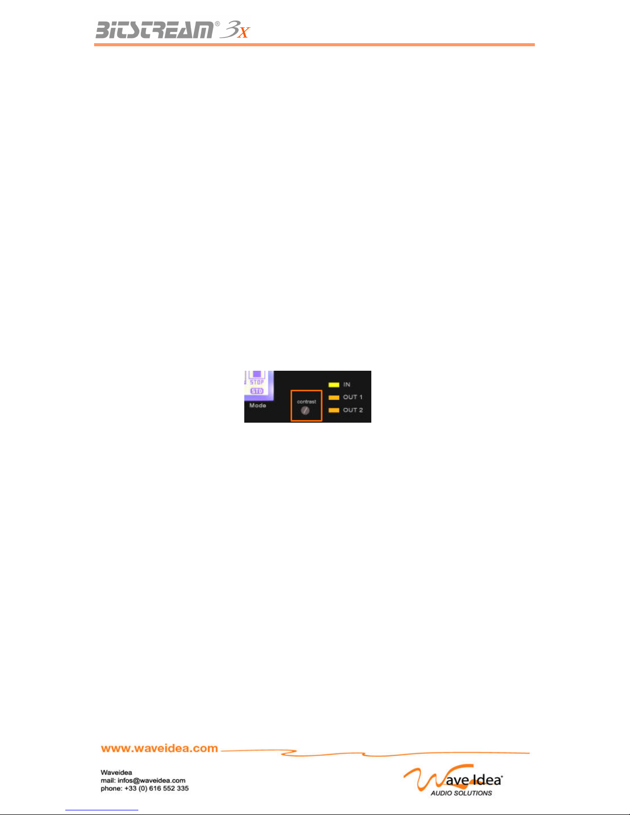
USER MANUAL
Initialisation of the Bitstream 3X
The Bitstream 3X can be initialized in user mode. It’s recommended that you do this after updating the
firmware or if there is any strange behaviour from the machine.
To initialize the Bitstream 3X, follow these steps:
1- The machine is turned off
2- Press and hold Edit – Ok – Group and turn on the machine
3- The initialization will start, the display will indicate the progression
4- Turn off and reboot the Bitstream 3X normally
Note 1: The initialization of the Bitstream 3X will take about 30 seconds
Note 2: The initialization of the Bitstream 3X impacts all the parameters and MIDI events associated to
User mode – it is therefore recommended to save your configurations before starting this process
(upload the MIDI assignments and parameters)
Regulating the contrast
The Bitstream 3X has a Backlight for the LCD screen for which the contrast can be adjusted
depending on the environment.
To regulate the contrast, you need a very fine/small flathead screwdriver. The adjuster is situated on
the right of the screen.
Rev 1.1 - Page 59
Page 60
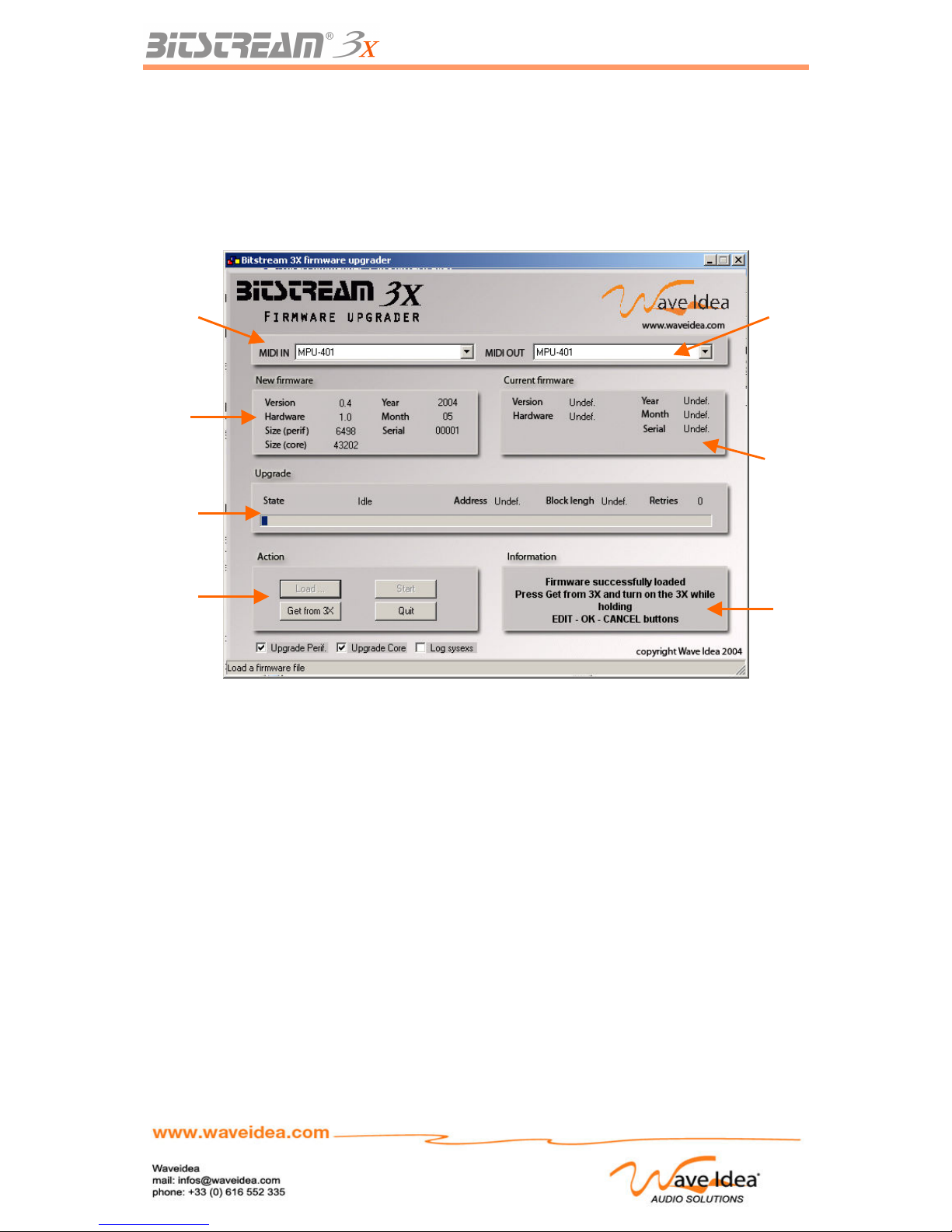
USER MANUAL
Updating the firmware
The Bitstream 3X features flash memory, which means that the firmware can be updated without
changing the chip and therefore without having to take apart the machine.
To avoid adding a specific connector for this function, updating the firmware can be done through MIDI
by using sysexs. Dedicated software (see the screen copy below) allows the user to update the
firmware by clicking several buttons.
Updating the firmware can be done in 4 distinct steps – needing to be done in this specific order:
1- Select MIDI input and output peripherals, where they are connected to the inputs and outputs
of the Bitstream 3X
2- Open the new firmware to be installed: file .bfw, using the button « Load ».
If a problem arrives during this step, contact the support team at Wave Idea.
3- Get information from the Bitstream 3X by pressing the button « Get from 3X »
If after a few seconds the user info zone indicates that the Bitstream 3X wasn’t found verify the
following:
o The MIDI inputs and outputs are selected and correspond to those of the Bitstream 3X
o The Bitstream 3X is on and functioning normally
o The MIDI cables aren’t deteriorated or disconnected
o See the Note at the end of this chapter
4- Update the Firmware by pressing « Start »
The progression bar should advance slowly until it’s full, and the user information zone should
display « success » at the end of the update.
IT IS IMPERATIVE THAT YOU DO NOT TURN OFF THE BISTREAM 3X DURING THE
UPDATE, AS DOING SO COULD DAMAGE THE MACHINE.
IF YOU ENCOUNTER ANDY PROBLEMS DURING THE UPDATE, CONTACT THE
SUPPORT TEAM AT WAVE IDEA
Note: If the Bitstream 3X is not detected after you’ve pressed the button « Get from 3X », and the
Rev 1.1 - Page 60
Selection of
the MIDI out
peripheral
Informations on
the new
firmware
User
Information
progression bar
for the update
Selection of
the MIDI In
peripheral
Information on
the actual
firmware
Action buttons
For the Update
Page 61
USER MANUAL
machine is on and in normal mode, another method can be used for the 3rd step:
3- The machine is off, press Edit – Ok – Cancel and turn on the machine while the
progression bar is advancing during the detection phase
If the machine is correctly detected, go to step 4, if not, contact the support team at Wave Idea
Once the update is finished, turn off and reboot the Bitstream 3X. It is possible that after the update,
the Bitstream 3X will need to be initialized see the dedicated chapter.
The version of the firmware accompanying the Bitstream 3X is displayed during the booting up of the
machine:
Reversal of the video mode
The screen of the Bitstream 3X can be configured in two modes: Normal or Reversed.
Depending on the environment and the preference of the user, one of these 2 modes can be selected
from the menus of the Bitstream 3X
Normal Mode: Blue characters on a white background
Reversed Mode: White characters on a blue background
Note 1: The default mode is « normal » mode
Note 2: When you have configured the video mode via the menus, the changes will take effect when
you leave the menus.
Menus associated to video mode
Rev 1.1 - Page 61
video mode Normal
Inverted
Selection of the video mode normal
Selection of the video mode reversed
Page 62
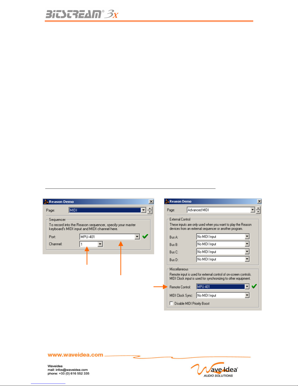
USER MANUAL
Usage Examples of the Bitstream 3X
Usage with a synthesizer software
The Bitstream 3X is pre-programmed to be used with all the synth software responding to MIDI.
The usage of the mode « Standard » allows the direct usage of the Bitstream 3X with the software
controllable in MIDI, without any programming required.
The only choices to be made are:
– The choice of the mode « Standard »
– The MIDI channel
For these choices, see the dedicated chapters.
For the software side, the user should be sure that it is ready to accept the MIDI events, and therefore
to be controlled by the Bitstream 3X. Two examples are shown below for the two most used software
systems, Propellerheads Reason and Ableton Live. The idea is the same for any other software:
– Choice of the MIDI peripheral which is connected to the Bitstream 3X
– Choice of the MIDI channel for the reception of the Bitstream 3X generated events
– Usage of the mode « Learn » to assign a control of the Bitstream 3X to a control of the software.
If you have a configuration problem, contact the support team at Wave Idea.
Propellerheads Reason
Choice of the MIDI Input peripheral and of the reception channel (Edit->Preferences)
Rev 1.1 - Page 62
Choice of the MIDI
In peripheral on
which is connected
the Bitstream 3X
and
Authorization of
the mode of
external control
Choice of the MIDI channel
of reception
corresponding to that of
Page 63
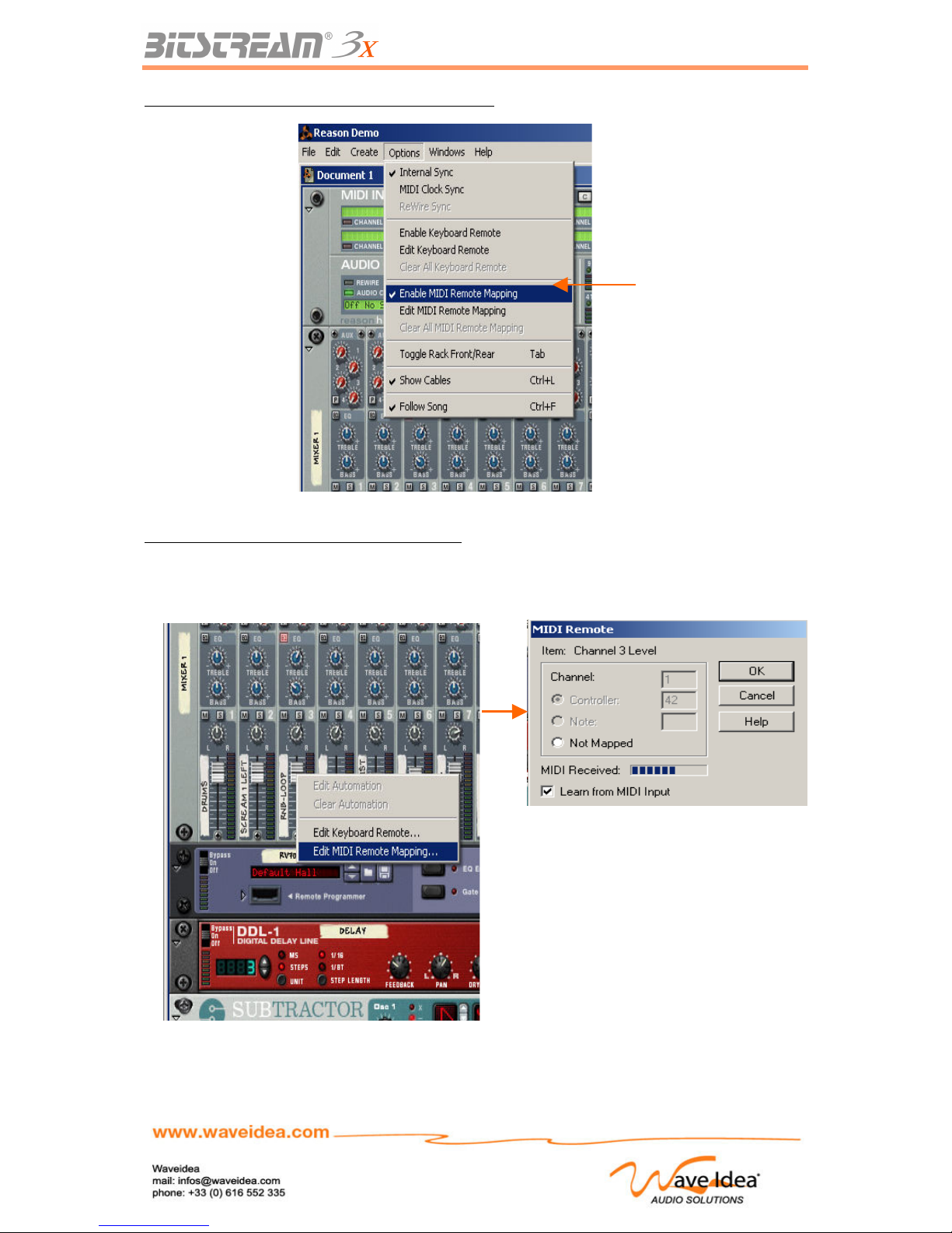
USER MANUAL
Authorization of the mode of external control (Options)
Using the mode « Learn » to allocate the controls
A right-click on the control to be assigned will open the contextual menu « Edit MIDI Remote
Mapping »; the mapping window will appear and allow the user to configure the control. The following
example shows the assigning of the slider « rnb-loop » from the mixing table:
In clicking « Learn from MIDI input » and in
changing the value of a control of the
Bitstream 3X, Reason detects the MIDI
message received and assigns modified
control automatically.
This operation should be repeated for each control to be assigned.
Rev 1.1 - Page 63
Authorization of the
mode of external control
Page 64
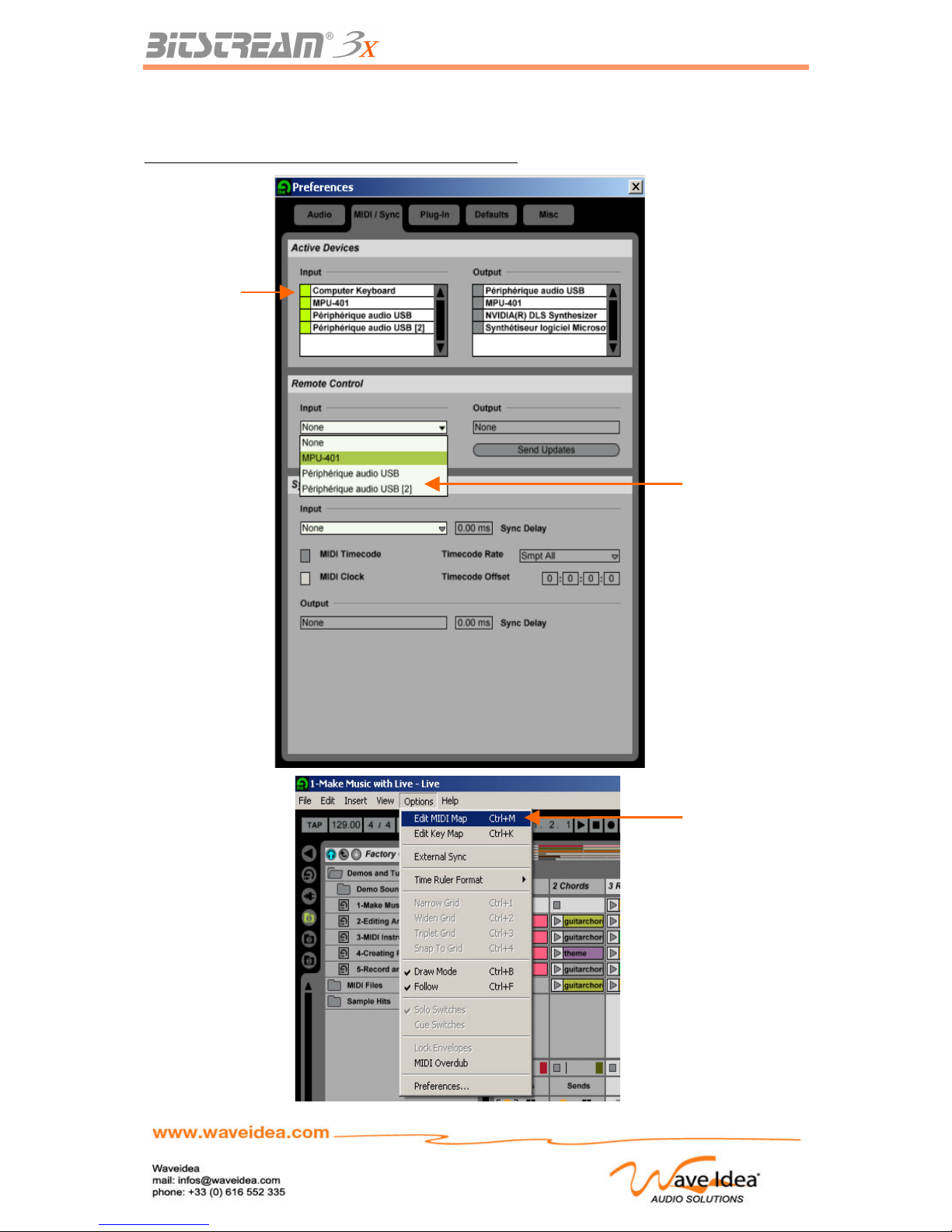
USER MANUAL
Ableton Live
Choice of the MIDI input peripheral (Option->Preferences)
Rev 1.1 - Page 64
Selection of the MIDI
port on which the
Bitstream 3X is
connected
List of the MIDI
peripherals
available
Editing assigned
MIDI controls
Page 65
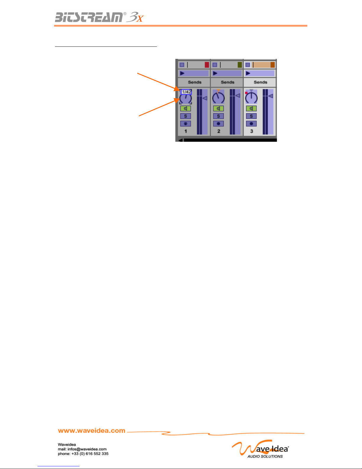
USER MANUAL
MIDI Map Editing for the different controls
Once Live is in mode « MIDI map editing », click on the control to assign and change the position of
one of the controls of the Bitstream 3X so it will be assigned automatically.
Live indicates the number of the channel and of the received control, above the control currently being
assigned.
Repeat this operation for all the controls to be assigned, and leave of the mode « MIDI map editing».
Rev 1.1 - Page 65
Selection of the
control to be
assigned
Channel and number
of the received
control
Page 66
USER MANUAL
Definition of the exclusive systems of the Bitstream 3X
The MIDI implementation of the Bitstream 3X is complete. All the parameters can be modified and
recalled by the exclusive systems sent and received.
Note: This part of the manual is for experienced users, wishing to decode the different exclusive
systems sent and received by the Bitstream 3X.
Note as well that the configuration software of the Bitstream 3X allows the reading or programming of
all the parameters of the Bitstream 3X, without any knowledge of MIDI, hexadecimal or otherwise.
Two types of parameters can therefore be programmed (downloaded) or recalled (uploaded):
- The global parameters
- The MIDI and LCD assignments
The global parameters are the parameters of the Bitstream 3X that do not correspond to the
assignments of the different controls; each global parameter has its own address, and can be
programmed or read.
The assignments are the parameters of configuration of the controls of the Bitstream 3X, which can be
one of two types:
- LCD : Assignment of alphanumeric chains destined for display
- MIDI : Assignments of the MIDI parameters
General Format of exclusive systems
The following table describes the general format of the exclusive systems dedicated to the Bitstream
3X, the different values are represented in Hexadecimal, as the MIDI standard describes them.
Octet Description Note
F0 Start of Exclusive System Always present
00 Wave Idea sysex ID Always present
20 Wave Idea sysex ID Always present
4F Wave Idea sysex ID Always present
00 Bitstream 3X ID Always present
01 Bitstream 3X ID Always present
ID0 Sysex ID 0 See description below
ID1 Sysex ID 1 See description below
ID2 Sysex ID 2 See description below
ID3 Sysex ID 3 See description below
DATA Sysex Data Variable Length - See description below
CS Checksum Cannot be present
F7 End of Exclusive System Always present
Note: The checksum CS is used to program the LCD and MIDI assignments, this octet is brought to 0
for the programming of the global parameters.
Rev 1.1 - Page 66
Page 67
USER MANUAL
Description of the octets Sysexs ID0 to ID3
Sysex ID0 Description Note
Bit 7 Always 0
Bit 6 Sysex direction 0:Sysex received 1:Sysex sent (BS3X)
Bit 5 Program/upload request/result 0 :program 1 :upload
Bit 4 Acknoledge request/result 0 :no ack 1 :ack 0 :error 1 :no error
Bit 3 Checksum check request 0:No Checksum to check 1:check
Bit 2 Reserved Must always be 0
Bits 1-0 Sysex content 0-0 : Global parameter
0-1 : LCD control assign
1-0 : Firmware update : (Must not be used)
1-1 : Midi control assign
Note : The two bits 1 and 0 of the octet Sysex_ID0, once they’re respectively equal to 1 and 0, are
reserved for the updating of the firmware, it is therefore imperative that you do not use Sysexs with the
bits having these values, as doing so could damage the Bitstream 3X
Sysex ID1 Description Note
Bit 7 Always 0
Bit 6-0 Sysex data lenght Range from 0 to 127
Sysex ID2 Description Note
Bit 7 Always 0
Bits 6-0 Global parameter address
LCD assign control index
MIDI assign control index
When Sysex ID0 bits 1-0 are 0-0
When Sysex ID0 bits 1-0 are 0-1
When Sysex ID0 bits 1-0 are 1-1
Sysex ID3 Description Note
Bit 7 Always 0
Bits 6-0 Always 0
LCD assign group index
MIDI assign group index
When Sysex ID0 bits 1-0 are 0-0
When Sysex ID0 bits 1-0 are 0-1
When Sysex ID0 bits 1-0 are 1-1
Description of the DATA octet(s)
The DATA octets drive the data to be programmed, in function of the parameter to be programmed;
these octets have different lengths, see the table which addresses the global parameters to know the
length of the data required for each parameter.
DATA Description Note
Bit 7 Always 0
Bits 6-0 Data to program (1 to 64 bytes)
LCD assign string (16 bytes)
MIDI assign data (32 bytes)
When Sysex ID0 bits 1-0 are 0-0
When Sysex ID0 bits 1-0 are 0-1
When Sysex ID0 bits 1-0 are 1-1
Rev 1.1 - Page 67
Page 68
USER MANUAL
List of the global parameters accessible via Sysexs
The following table lists the global parameters of the Bitstream 3X, as well as their respective
addresses
Global
parameter
address
Description Data length / Range
(bytes) / (Value)
Note
00 (1) Reserved Reserved Must not be used
01 (1) Reserved Reserved Must not be used
02 (1) Reserved Reserved Must not be used
03 Bs3x status 0 1 / (0-7F) See description below
04 Bs3x status 1 1/ (0-7F) See description below
05 Bs3x status 2 1/ (0-7F) See description below
06 MIDI Channel 1/ (0-F) Select Midi channel 0-15 (1-16)
07 Group 1/ (0-14) Select group 0-20
08 Scene 1 / (0-63) Select scene 0-99
09 Infrared hold 1 / (0-7F) Infrared hold value
0A Current function 1 / (0-2) 0 :channel 1 :scene 2 :group
0B Current
automation
1 / (1-3) 0 :reserved 1 :LFO 2 :arppeggio
3 :motion sampler
0C Motion part select 1 / (0-7) Select motion part 1-8
0D LFO level 1 / (0-3F) Select LFO level 0-63
0E LFO frequency 1 / (0-7) Select LFO frequency 0-7
0F LFO offset 1 / (20-5F) Select LFO offset 32-95
10 Arpp gate 1 / (0-5) Select arpeggio gate 0-5
11 Arpp accent 1 / (0-7F) Select arpeggio accent 0-127
12 Arpp rythm 1 / (0-7F) Select arpeggio rythm 0-127
13 Arpp range 1 / (0-0F) Select arpeggio range 1-16
14 Arpp transpose 1 / (0-7F) Select arpeggio transp -63 +64
15 Arpp melody 1 / (0-17) Select arpeggio melody 0-23
16 Arpp direction 1 / (0-5) Select arpeggio dir up-C2
17 Arpp resolution 1 / (0-6) Select arpeggio clock resolution
18 Arpp channel 1 / (0-0F) Select arpeggio MIDI channel
19 Arpp velocity 1 / (0-7F) Select arpeggio velocity 0-127
1A Arpp swing 1 / (0-7F) Select arpeggio swing 0-127
1B Arpp melody bank 1 / (0-0) Select arpeggio melody bank
1C Arpp rythm bank 1 / (0-3) Select arpeggio rythm bank 0-3
1D Arpp accent bank 1 / (0-3) Select arpeggio accent bank 0-3
1E Arpp mode 1 / (0-3) Select arpeggio synch mode 0-3
1F Arpp offset 1 / (0-47) Select arpeggio offset -23 +24
20 Internal tempo 2 / (0-7F) Select tempo 30-255, tempo is
accessed via 2 nibbles, MSB first
21 User curve 0 low 40 / (0-7F) 64 low bytes of user curve 0
22 User curve 0 high 40 / (0-7F) 64 high bytes of user curve 0
23 User curve 1 low 40 / (0-7F) 64 low bytes of user curve 1
24 User curve 1 high 40 / (0-7F) 64 high bytes of user curve 1
25 Group name 1C / (‘0-9’ – ‘a-Z’) 28 Nibbles of group string name
MSB First , 14 bytes total
26-7E (1) Reserved Must not be used
7F (2) identitty 0B See description below
(1) These parameters should not be programmed
(2) These parameters are not accessible except in Read format
(3) All numbers in the above table are hexadecimal
Rev 1.1 - Page 68
Page 69
USER MANUAL
Description of the octet Bs3x status 0
Bs3x status 0 Description Note
Bit 7 Always 0
Bit 6 Arppeggio sync mode 0:internal 1:external
Bit 5 Reserved
Bit 4 Arppegio USB output 0:disable 1:enable
Bit 3 Arppegio MIDI Out 1 output 0:disable 1:enable
Bit 2 Arppegio MIDI Out 2 output 0:disable 1:enable
Bit 1 Reserved
Bit 0 SHIFT button behaviour 0: SHIFT locks MIDI channel insertion
1: SHIFT doesn't lock MIDI channel insertion
Description of the octet Bs3x status 1
Bs3x status 1 Description Note
Bit 7 Always 0
Bit 6 Analog behaviour 0:jump 1:hook
Bit 5 Motion sampler sync mode 0:internal 1:external
Bit 4 Infrared controller state 0:off 1:on
Bit 3 LFO state 0:off 1:on
Bit 2 LFO sync mode 0:internal 1:external
Bit 1 Motion sampler state 0:off 1:on
Bit 0 Motion sampler mode 0:single shot 1:loop
Description of the octet Bs3x status 2
Bs3x status 2 Description Note
Bit 7 Always 0
Bits 6-5 LFO waveform 0-0 : sine
0-1 : triangle
1-0 : square
1-1 : random
Bits 4-3 Bs3x operating mode 0-0:standard
0-1:user
1-0: Reason
1-1: reserved
Bit 2 LCD video mode 0: normal
1: inverted
Bit 1 Reserved
Bit 0 SHIFT button behaviour 0: SHIFT locks MIDI events
1: SHIFT doesn't lock MIDI events
Rev 1.1 - Page 69
Page 70
USER MANUAL
Example of communication
Request to read the identity of the Bitstream 3X (global parameter, address 7F)
Sysex sent: F0 00 20 4F 00 01 30 0B 7F 00 F7
Sysex ID 0 = 30 = 00110000 (global parameter upload request, received sysex)
Sysex ID 1 = 0B (identity data length)
Sysex ID 2 = 7F (identity address)
Sysex ID 3 = 00 (always 00 for global parameters)
Response of the Bitstream 3X
Octet (byte) Description Note
F0 Start of exclusive system
00 Wave Idea sysex ID
20 Wave Idea sysex ID
4F Wave Idea sysex ID
00 Bitstream 3X ID
01 Bitstream 3X ID
ID0 Sysex ID 0 70 (global parameter upload, sysex sent)
ID1 Sysex ID 1 0B (identity length)
ID2 Sysex ID 2 7F (identity address)
ID3 Sysex ID 3 00 (always 00 for global parameters)
FW_VERSION Version of the firmware Example : 01
FW_SUB_VERSION Sub version of the firmware Example : 00 (Firmware V1.0)
HW_VERSION Version of the hardware Example : 01
HW_SUB_VERSION Subversion of the hardware Example : 02 (Hardware V1.2)
MANUF_YEAR Year Manufatured Example : 01 (January)
MANUF_MONTH Month Manufactured Example : 05 (2005)
SERIAL_4 Manufactured serie Example : 01 (1st series made)
SERIAL_3 Serial number Example : 00
SERIAL_2 Serial number Example : 00
SERIAL_1 Serial number Example : 00
SERIAL_0 Serial number Example : 01 (Number of series 00001)
F7 End of exclusive system
Definition of MIDI data assign accessible via Sysexs
The following table describes the 32 bytes of MIDI configuration assign for a control of the Bitstream
3X
Each octet is sent / received in the form of 2 nibbles; the MSB is sent/received first.
To configure a control of the Bitstream 3X, 64 nibbles of data will be therefore sent in the Sysex, in
addition to the heading of the Sysex. A checksum calculated based on the total of the data from the
sysex will be equally calculated and inserted just before the end marker of the sysex F7.
The programming of the control can be done with or without a request and acknowledgement, the
Bitstream 3X will return or not an acknowledge sysex indicating the result.
Example: if the byte to be sent is 27 in hexadecimal, the 2 nibbles will be 02 followed by 07
Rev 1.1 - Page 70
Page 71
USER MANUAL
Complete structure associated with a control of the Bitstream 3X
Byte Description Note
0 Ctrl_status_0 Reserved to standard operating mode
See description below
1 Ctrl_status_1 Reserved to standard operating mode
See description below
2 Ctrl_status_2 Reserved to user operating mode
See description below
3 MIDI string lenght Range from 0 to 14 (0 to 20)
4 MIDI channel position Range from 0 to 14 (0 to 20)
0: Fixed Midi channel
5 Control value 1 position Range from 0 to 14 (0 to 20)
0: No control value 1 inserted
6 Control value 2 position Range from 0 to 14 (0 to 20)
0: No control value 2 inserted
7 Control Min value Range from 0 to 7F (0 to 127)
8 Control Max value Range from 0 to 7F (0 to 127)
9 Checksum Start position Range from 0 to 14 (0 to 20)
0: No checksum inserted
10 Control chained See description below
0: No control chained
11-31 MIDI string bytes Up to 42 nibbles – MSB first
Up to 21 Midi string bytes
Description of the octet Ctrl_status_0
Ctrl_status_0 Description Note
Bit 7 Selection CC / Note for standard mode 0=CC, 1=Note
Bits 6-0 CC or Note number for standard mode Range from 0 to 127
Description of the octet Ctrl_status_1
Ctrl_status_1 Description Note
Bit 7 Switch behaviour 0=push, 1=toggle
Bit 6 Scene exclude 0=No 1 :control excluded from snapshots scenes
Bit 5 Auto-send at startup 0=No 1 :control send at startup
Bit 4 USB Out enable 0 :Disable 1 :control sent on USB output
Bit 3 MIDI Out 1 enable 0 :Disable 1 :control sent on MIDI output 1
Bit 2 MIDI Out 2 enable 0 :Disable 1 :control sent on MIDI output 2
Bits 1-0 MIDI delay insertion 00:No delay 01:30ms 10:60ms 11:90ms
Description of the octet Ctrl_status_2
Ctrl_status_2 Description Note
Bits 7-4 Reserved
Bit 3 Split control value 0: send value as a 7 bits number
1: split 7 bits control value in 2 nibbles, and send
them on control value positions 1 & 2 in the MIDI
string
Rev 1.1 - Page 71
Page 72
USER MANUAL
Bits 2-0 Control curve model 000: linear
001: invert linear
010: logarithmic
011: invert logarithmic
100: random
101: user curve 0
110: user curve 1
111: reserved
Description of the octet Control chained
Ctrl_chained Description Note
Bit 7 Virtual cross-fader 0 :disable 1 :enable
Bits 6-0 Control number chained 0: No control chained
1-67 : Control number chained minus 1
The general format of the sysex to be sent to the Bitstream 3X in order to reassign a control will be as
follow:
F0 00 20 4F 00 01 ID0 ID1 ID2 ID3 < 64 Nibbles of data > CS F7
ID0 : 19 = 00011001 = programming with acknowledgement
ID1 : 40 = Length of the data included in the Sysex (64 nibbles = 32 octets)
ID2 : 08 = Number of the control to be programmed example : slider 1 (control # 08)
ID3 : 04 = Programming of the control in group 04
CS : Checksum calculated based on the 64 nibbles of data similar to Roland :
(Sum (64 nibbles) Modulo 128)
When programming with acknowledgement, the Bitstream 3X will return a sysex indicating the result of
the programming:
F0 00 20 4F 00 01 ID0 ID1 ID2 ID3 00 F7
ID0 : 51 = 01010001 = programming success, sysex exiting
ID1 : 01 = Length of the data included in the Sysex
ID2 : 08 = Number of the control programmed example : slider 1 (control # 08)
ID3 : 04 = Control programmed on group 04
Definition of the LCD assign data accessible via Sysexs
The following table describes the 16 octets of LCD assign configuration of a control of the Bitstream 3X
Each octet is sent / received in the form of 2 nibbles, the MSB being sent/received first.
To configure a Bitstream 3X control, 32 nibbles of data will be sent in the Sysex, followed by the
checksum calculated based on these 32 nibbles of data.
Example : if the octet to be sent is ‘A’, it’s ascii corresponding code is 41 in hexadecimal, the two
nibbles will be 04 followed by 01
Byte Description Note
0-15 LCD string 32 nibbles of LCD string – MSB First
16 bytes of LCD string (‘0-9’ – ‘a-Z’)
Rev 1.1 - Page 72
Page 73

USER MANUAL
MIDI Overview
This chapter presents a brief overview of the Musical Instrument Digital Interface—MIDI. You should
also have a more detailed reference on the subject, especially if you need to understand advanced
features not covered here, such as MIDI Time Code and Sample Dump Standard.
Introduction
The MIDI specification details a combination of hardware and software, enabling synthesizers,
computers, effects, and other MIDI devices to communicate with each other. Communication may be
one-way (sending or receiving) or two-way (sending and receiving). For instance, a simple effects
processor might have only MIDI input, to allow remote MIDI selection of program number. Synthesizers
usually have MIDI input and output. They can receive requests to play notes from other keyboards or
from a computer, and they can send notes played on the unit's own keyboard. Program changes and
actual program information can be sent and received.
Numbers and conventions
Often, MIDI documentation refers to number values in decimal, hexadecimal (often called hex), or
binary, as is convenient. Tables often denote MIDI bytes as binary, such as 1011nnnn or 0vvvvvvv.
Otherwise, if not noted or obvious, assume decimal. Hexadecimal is used as a shorthand for binary,
usually preceded by a dollar sign ($)—as in this text—or followed by an H. (For instance, $7E and 7EH
stand for hexadecimal 7E.)
MIDI hardware interface
The MIDI interface operates at 31.25 Kbaud, which works out to 320 microseconds per byte. Since
most MIDI messages consist of two or three bytes, this means that it takes less than a millisecond to
send a MIDI command.
The serial data is transferred in a current loop configuration. Many devices have a MIDI thru, which
simply passes the MIDI input. You may use these to daisy-chain MIDI devices, but a chain of three
devices is the practical limit, since each thru adds timing distortion to the MIDI signal, making it difficult
for the receiver to interpret the data correctly. Y-cords are not appropriate for either splitting or
combining MIDI data. You must use MIDI thru boxes to distribute, and mergers to combine MIDI
streams.
Proper MIDI cables are made from shielded twisted pair cable, and should be a maximum length of 50
feet (15 meters). (Beyond using quality built MIDI cables, there is no advantage to using expensive or
esoteric cables. They have no effect on the MIDI transfer or the sound quality of your instrument.)
As a final hardware note, the thoughtful folks that brought us MIDI deemed that the connections would
be opto-isolated. This eliminates the possibility of ground loops through the MIDI cables. Also, you will
not harm your MIDI ports if you accidentally plug an output into another output (but it won't do anything
interesting either).
MIDI data format
MIDI communications happen through multibyte messages consisting of one status byte, optionally
followed by one or two data bytes, except for system exclusive messages, which have an arbitrary
number of data bytes. Status bytes have their most significant bit (MSB) set to differentiate them from
data bytes, so status bytes range in value from 128 ($80) to 255 ($FF), while data bytes range from 0
to 127 ($7F).
MIDI supports 16 message channels, letting you link multiple devices while maintaining individual
control. Messages sent on specific channels, such as note on and note off, are called channel
messages. Messages that are not channel oriented are called system messages. See
Table 1 at the
Rev 1.1 - Page 73
Page 74

USER MANUAL
end of this chapter for a summary of MIDI messages.
Channel messages
Channel messages contain their channel number in the lower four bits of the status byte. A value of 0
corresponds to channel 1, 1 to channel 2, and so on, up to a value of 15 (for MIDI channel 16). When
status bytes are listed as 1011nnnn (binary), the nnnn part refers to the channel part of the status byte.
Similarly, in $Bn, the n refers to the channel part, in hexadecimal.
There are two types of channel messages: mode and voice. Mode messages are used to control the
polyphony of a synthesizer, and to send all notes off commands. Voice messages are those that
control a particular synthesizer voice on a particular channel.
Mode
MIDI allows for several variations in assigning voices to the 16 MIDI channels. These variations are
controlled by channel mode messages. The status byte for channel mode messages is the same as for
control change messages (a channel voice message). The two are differentiated by the data byte that
follows, which is 0-120 for controllers and 121-127 for mode messages.
The mode messages give you control over whether omni is on or off, and whether the unit is
responding in poly (voices assigned polyphonically) or mono (voices assigned monophonically) mode.
Omni determines whether the device is responding to voice messages on a given channel (omni off),
or to voice messages on all channels (omni on). These messages carry an implicit all notes off
command. A separate all notes off mode message is also available.
Some modes let a device respond to more than one MIDI channel at a time. Mode messages are
recognized by a receiver only when sent on the basic channel to which the receiver is assigned,
regardless of the current mode. Since the modes implemented by a MIDI device are dependent on the
actual hardware design, refer to your manual to get a more complete description.
Voice
Voice messages may be received on the basic channel and on other channels—all called voice
channels—that are related specifically to the basic channel, depending on which mode has been
selected.
Voice messages include all the messages that affect a specific instrument voice, such and note on
and note off, pitch bend, modulation, aftertouch, and program number.
System messages
System messages are not encoded with channel numbers. There are three types of system messages:
common, real-time, and exclusive.
Common
System common messages are intended for all units in a system, and include such messages as song
select and tune request.
Real-Time
System real-time messages consist of a single status byte, and are used for timing and start/stop
information. Real-time messages may be interspersed in the MIDI data stream, even within a multibyte
message, without affecting the current status. Real-time messages are usually intercepted or
generated at the MIDI driver level and used for timing information (when clocking externally, for
instance); generally, you will not have to deal with these directly.
Rev 1.1 - Page 74
Page 75

USER MANUAL
Exclusive
System exclusive (or sysex) messages are used to transfer information that may be specific to a given
MIDI device. Generally, the actual data that is used describe a sound (usually called a program or
patch) is not usable by another device, even from the same manufacturer. This is because the sound
generating architecture varies dramatically between devices.
System exclusive messages begin with the system exclusive status byte (240, or $F0), followed by a
manufacturer's ID code. The number of data bytes that follow are determined by the manufacturer.
Finally, the message is terminated by an end of exclusive (EOX) status byte (247, or $F7). So as not to
get stuck reading an endless system exclusive message if the EOX is missing, the MIDI specification
states that any status byte (other than real-time) acts to terminate a system exclusive message.
If you want to write a device editor or librarian stack, you will be primarily concerned with system
exclusive messages. The device's maker specifies its system exclusive format. Some manufacturers
include a detailed system exclusive specification with each unit they sell. Others requires that you
contact them directly to request system exclusive documentation for the device.
System exclusive messages usually get sent as a result of requesting them, either by sending a
system exclusive message to your device requesting a patch dump, or by a front panel invocation. As
with all MIDI messages, if you receive a system exclusive message that you don't understand or are
not interested in, simply ignore it and all associated data bytes.
A final note on system exclusive: Since this is the most flexible form of MIDI message, you might
expect that this is where extensions to the MIDI specification would take place. Well, extensions have
already been added here, with certain MIDI Time Code messages—which help to marry MIDI with
SMPTE Time Code—and with the Sample Dump Standard format.
Additional status notes
Here are some notes on special status conditions and messages.
Running status
Channel messages (voice and mode) can have running status. That is, if the next channel status byte
is the same as the last, it may be omitted. The receiver assumes that the accompanying data is of the
same status as was last sent. Receipt of any other status byte except real-time terminates running
status.
Running status is especially convenient for sending strings of note-on and note-off messages, when
using "note on with velocity of 0" for note off, and for output of continuous controllers. This allows you
to cut the length of such strings by one-third.
Undefined and unimplemented status
Undefined status bytes are reserved and should not be used. Any undefined or unimplemented status
bytes received should be ignored. Any subsequent data bytes should be ignored until the next legal
status byte is received. In this way, these unused status bytes can be added to the MIDI specification
in the future without breaking your program.
Rev 1.1 - Page 75
Page 76

USER MANUAL
Table 1: MIDI byte value summary
Message Hex Decimal Data byte count
data 00-7F 0-127
na
Channel messages
Note off
8n 128+n
2
Note on
9n 144+n
2
Polyphonic key pressure
An 160+n
2
Control/Mode change
Bn 176+n
2
Program change
Cn 192+n
1
Monophonic channel pressure Dn 208+n 1
Pitch bend change
En 224+n
2
System exclusive
System exclusive status F0 240 variable
System common
MIDI Time Code (MTC) F1 241 1
Song position pointer F2 242 2
Song select F3 243 1
(Undefined) F4 244 0
Cable select* F5 245 1
Tune request F6 246 0
End of exclusive (EOX) F7 247 0
System real-time
Timing clock F8 248 0
(Undefined) F9 249 0
Start FA 250 0
Continue FB 251 0
Stop FC 252 0
(Undefined) FD 253 0
Active sense FE 254 0
System reset FF 255 0
Note: n is the channel number - 1 (0 is channel 1, 1 is channel 2, ...).
* Though officially undefined, some MIDI interfaces use this message to control cable access; a single
data byte that follows designates the cable number on which subsequent MIDI messages are routed.
Rev 1.1 - Page 76
Page 77

USER MANUAL
128 controllers defined in the MIDI standard:
1
Modulation
33
Modulation LSB
65
Porta Pedal
97
Data decrement
2
Breath Control
34
Breath Control LSB
66
Sostenuto Pedal
98
NRPN LSB
3
Control 3
35
Aftertouch LSB
67
Soft Pedal
99
NRPN MSB
4
Foot Control
36
Foot Control LSB
68
Legato
Footswitch
100
RPN LSB
5
Portamento
Time
37
Portamento Time
LSB
69
Hold Pedal 2
101
RPN MSB
6
Data Entry MSB
38
Data Entry LSB
70
Sound Variation
102
Control 102
7
Volume
39
Volume LSB
71
Resonnance
103
Control 103
8
Balance
40
Balance LSB
72
Release Time
104
Control 104
9
Control 9
41
Control 41
(Control 9 LSB)
73
Attack Time
105
Control 105
1
0
Pan
42
Pan LSB
74
LPF Cutoff
106
Control 106
1
1
Expression
43
Expression LSB
75
Control 75
107
Control 107
1
2
Control 12
44
Control 44
(Control 12 LSB)
76
Control 76
108
Control 108
1
3
Control 13
45
Control 45
(Control 13 LSB)
77
Control 77
109
Control 109
1
4
Control 14
46
Control 46
(Control 14 LSB)
78
Control 78
110
Control 110
1
5
Control 15
47
Control 47
(Control 15 LSB)
79
Control 79
111
Control 111
1
6
Control 16
48
Control 48
(Control 16 LSB)
80
Control 80
112
Control 112
1
7
Control 17
49
Control 49
(Control 17 LSB)
81
Control 81
113
Control 113
1
8
Control 18
50
Control 50
(Control 18 LSB)
82
Control 82
114
Control 114
1
9
Control 19
51
Control 51
(Control 19 LSB)
83
Control 83
115
Control 115
2
0
Control 20
52
Control 52
(Control 20 LSB)
84
Portamento
116
Control 116
2
1
Control 21
53
Control 53
(Control 21 LSB)
85
Control 85
117
Control 117
2
2
Control 22
54
Control 54
(Control 22 LSB)
86
Control 86
118
Control 118
2
3
Control 23
55
Control 55
(Control 23 LSB)
87
Control 87
119
Control 119
2
4
Control 24
56
Control 56
(Control 24 LSB)
88
Control 88
120
All Sound off
2
5
Control 25
57
Control 57
(Control 25 LSB)
89
Control 89
121
Resand all
Controlers
2
6
Control 26
58
Control 58
(Control 26 LSB)
90
Control 90
122
Local Control
2
7
Control 27
59
Control 59
(Control 27 LSB)
91
Reverb
123
All Note off
2
8
Control 28
60
Control 60
(Control 28 LSB)
92
Tremolo depth
124
Omni Mode off
2
9
Control 29
61
Control 61
(Control 29 LSB)
93
Chorus Depth
125
Omni Mode on
3
0
Control 30
62
Control 62
(Control 30 LSB)
94
Dandune
126
Mono Mode on
3
1
Control 31
63
Control 63
(Control 31 LSB)
95
Phaser Depth
127
Poly Mode on
Rev 1.1 - Page 77
Page 78
USER MANUAL
Technical Characteristics
35 assignable knobs
8 assignable faders 45 mm
16 assignable buttons
Joystick –analog, assignable, 2 axes
Infrared Controller, assignable
Cross-fader, assignable
Encoder – footswitch entry
7 response models, per control (lin, inv lin, log, inv log, random, users 0 & 1)
SYNC24 Output
Extension port
Integrated LFO programmable
Arppeggiator, evolved
Motion sampler
MIDI IN / THRU / OUT 1 / OUT 2
USB compatible
Plug and play
Auto powered from USB port
Transport Bar
Completely programmable
Large graphic LCD screen with backlight
Configuration Software
100 Scene Memories
21 programmable groups
Analog Mode « jump less »
MIDI Merger and filter
4U Metal Box (rackable option)
Dimensions 420 x 180 x 25/46 mm
Weight: around 4.7 Kg
Consumption : env. 400mA
Delivered with adapter sector, USB cable, Wave Idea Cd-rom, protection cover
Guarantee 1 year
Rev 1.1 - Page 78
Page 79
USER MANUAL
Retailler
Rev 1.1 - Page 79
 Loading...