

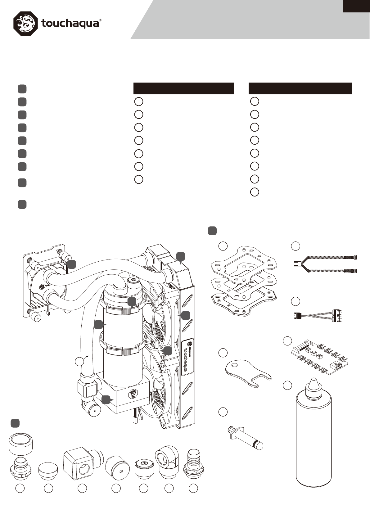
Accessories
English
BPTA-IPSGDIO-SA Installation Guide
Radiator
A
Fan
B
Radiator mount bracket
C
Water tank mount bracket
D
Pump
E
Water tank system
F
CPU water block
G
Fittings
H
(See following details)
Other accessories
I
(See following details)
...............1 PCS
...................2 PCS
.................1 PCS
......1 PCS
...............1 SET
G
.1 PCS
.2 PCS
....1 PCS
.1 SET
H.
Fittings
1
TA-CFS3858-GB
TA-F06-GB
2
TA-TRC-GS
3
BPTA-EFW-GS
4
BPTA-EXAIR-GS
5
BPTA-90RE-GS
6
BP-BB2WP-P02
7
.......6 PCS
.............1 PCS
...........1 PCS
.........1 PCS
.......1 PCS
........1 PCS
........1 PCS
Other accessories
I
9
A
I. Other Accessories
Soft tube
8
CPU backplane set
9
Y wire(Fan)
10
Y wire(DRGB)
11
Fitting nut wrench
12
DRGB Multi Function Controller
13
Thermal grease
14
Coolant
15
...............1 PCS
..........1 PCS
..........1 PCS
.........1 PCS
................2 PCS
10
.....1 SET
.....1 PCS
.1 PCS
H
Fittings
D
11
B
F
13
C
8
12
15
E
14
1 2
3 4 5 6 7
P 1
Bitspower reserves the right to change the product design and
interpretations. These are subject to change without notice. Product
colors and accessories are based on the actual product.
V2

Alternative build
P 2
V2

1
Install the water tank flap
F
1
E
3
The water tank base and water pump should not be disassembled.
Disassembly will void the warranty.
P1M Pump Spec.
5
1
Digital RGB PIN on motherboard or other equipment.
Power/Voltage:12V DC
DC power:≤6W
Electric connector:4-pin fan connector
Maximum revolution:2200±5%RPM
Noise:≤26 dBA/m
!
Soft tube installation steps:
1. Pull the fitting apart by unscrewing the
sleeve from the nut.
2. Slide the tube through the sleeve then push
the tube over the nut head until the end.
3. Lock the nut tightly to the sleeve using a
clockwise rotation.
2
Soft tube installation warning
8
CLOSE
A B C
A Negative electrode -
B Positive electrode +
C Speed message FG
Connect to motherboard.
1
OPEN
12
6
4
2
Install the fans and reservoir on the radiator
M4x10 Screw
M4x30 Screw
M4 Nut
D
C
13
motherboard DRGB Multi Function Controller
A
1
B
M4x6 Screw
P 3
V2

3
Install the CPU
Apply block over AMD CPU
Installation 1
96
90
AMD SOCKET AM4
AMD SOCKET AM3 / AM3+
AMD SOCKET AM2 / AM2+
AMD SOCKET FM1 / FM2+
DRGB LED
Digital RGB PIN on motherboard or other equipment.
13
motherboard DRGB Multi Function Controller
INOUT
AMD SOCKET 939 / 754 / 940
AMD SOCKET AM4
48
54
AMD SOCKET AM3 / AM3+
AMD SOCKET AM2 / AM2+
AMD SOCKET FM1 / FM2+
Please closely follow this diagram for installation.
SCM3FL20
SPRING
1mm SPACER
CPU Block
CPU Block PLATE(AM4)
SCM3F6
1mm SPACER
Use an appropriate amount
of thermal paste.
14
4
Wire
Connect the Addressable RGB(+5V)Light
10
11
−
+
FG
PWM
Master
−
+
FG
PWM
−
+
PWM
Back Pad
3M Paste Pad
Metal Backplane
M3x32mm SCREW
Slave
P 4
V2

5
Install the tube with fitting
1
1
Optimum water route
P 5
V2

6
Water
Pour the coolant into the reservoir via the water filling hole. Once the reservoir is 90% full, turn on the power supply for the pump to run and let the air
exit the loop. Turn off the power supply when the reservoir is near empty. Repeat until all the air has exited the loop.
Notice:
Bitspower recommends that consumers add the Bitspower coolant or purified water for
their water-cooling liquid. If the consumer chooses different water-cooling liquids, the
resulting impurities may cause peeling of the coating on some of the hardware, water
channels blockage by built-up residue, improper operation of the water pump, water
tank tube breakage, and o-rings deformation leading to leakage. Any issues related to
the use of inappropriate water-cooling liquid will be the responsibility of the consumer.
Do not turn on the pump if the reservoir is empty.
Drain
Water filling hole
7
Digital RGB Multi Function Controller
Mode+ Mode-Speed
Power
DRGB
7
Connect the tube
◆Press MODE+ and MODE- buttons simultaneously
and release at the same time to enter auto mode.
motherboard
The DRGB controller is used to expand the amount of DRGB header of the motherboard. The controller can expand one DRGB header into eight, and control
multiple fans and LED strips compatible light effects controlled by the motherboard. In addition, the controller has its own lighting effects, which can be
controlled by the buttons found on the controller.
ATTENTION:
1: The controller can't increase the power supply of the DRGB header from the motherboard. A standard DRGB header can provide 5Vx1A=5W of power.
It is recommended that the combined length of the LED strip connected to the controller be shorter than 1 meter. If the DRGB header is overloaded, the
brightness of the light will be reduced considerably. To restore the brightness, some items plugged to the controller must be removed.
2: Connection tip - Keep in mind that the arrow marks on the connector corresponds to 5V pin for the DRGB headers.
3: When using the controller separately, please connect to a SATA port only. For synchronized light effect with the motherboard, you have to remove the
power supply from the SATA port and connect to the motherboard directly.
Specifications:
Operating voltage: DC 5V input
Power: Less than 1W
P 6
V2
 Loading...