


4
4-37
Model L Series
Thermal Shock plus Power Conditioning ∆R 0.70%
Short Time Overload ∆R 0.25%
Terminal Strength ∆R 0.25%
Moisture Resistance ∆R 0.50%
Mechanical Shock ∆R 0.25%
Vibration ∆R 0.25%
Low Temperature Storage ∆R 0.25%
High Temperature Exposure ∆R 0.50%
Load Life, 1,000 Hours ∆R 1.00%
Resistance to Solder Heat (Per MIL-STD-202, Method 210, Cond.B) ∆R 0.25%
Dielectric Withstanding Voltage 200V for 1 minute
Marking Permanency MIL-STD 202, Method 215
Lead Solderability MIL-STD 202, Method 208
Flammability UL-94V-O Rated
Storage Temperature Range -55°C to +150°C
MODEL L SERIES
Thick Film
Low Profile SIP
Conformal Coated
Resistor Networks
Specifications subject to change without notice.
ENVIRONMENTAL
ELECTRICAL
Standard Resistance Range, Ohms 22 to 1Meg
Standard Resistance Tolerance, at 25°C ±2%
Optional: ±1% (F Tol.), ±5% (J Tol.)
Operating Temperature Range -55°C to +125°C
Temperature Coefficient of Resistance ±100ppm/°C (<100 Ohms = ±250ppm/°C)
Temperature Coefficient of Resistance, Tracking ±50ppm/°C
Maximum Operating Voltage 100Vdc or √PR
Insulation Resistance ≥10,000 Megohms
4-38
Model L Series
-3 Circuit
(
Isolated Resistors
) &
-1 Circuits
(
Bussed Resistors
)
Ohms Code Ohms Code Ohms Code
22 220 820 821 33K 333
27 270 1K 102 39K 393
33 330 1.2K 122 47K 473
39 390 1.5K 152 51K 513
47 470 1.8K 182 56K 563
51 510 2K 202 68K 683
56 560 2.2K 222 82K 823
68 680 2.7K 272 100K 104
82 820 3.3K 332 120K 124
100 101 3.9K 392 150K 154
120 121 4.7K 472 180K 184
150 151 5.1K 512 200K 204
180 181 5.6K 562 220K 224
200 201 6.8K 682 270K 274
220 221 8.2K 822 330K 334
270 271 10K 103 390K 394
330 331 12K 123 470K 474
390 391 15K 153 510K 514
470 471 18K 183 560K 564
510 511 20K 203 680K 684
560 561 22K 223 820K 824
680 681 27K 273 1Meg 105
Ohms Code Ohms Code Ohms Code
R1/R2 R1/R2 R1/R2 R1/R2 R1/R2 R1/R2
180/390 181/391 330/390 331/391 3K/6.2K 302/622
220/270 221/271 330/470 331/471
220/330 221/331 330/680 331/681
MECHANICAL
Lead Material Steel Alloy (Standard)
Copper Alloy (Optional)
Lead Finish 90/10 Tin-Lead
Substrate Material Alumina
Resistor Material Cermet
Body Material Conformal Epoxy Resin
STANDARD RESISTANCE VALUES, OHMS
-5 Circuit
(Dual Terminators)
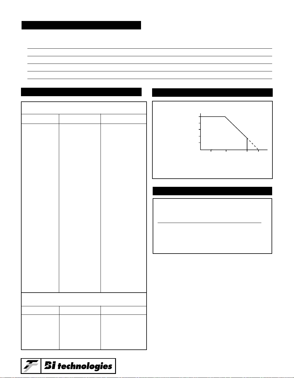
POWER DERATING CURVE
POWER DISSIPATION, WATTS AT 70°C
— Resistor (Per Circuit) —
Model Package -1 -3 -5
L06 .6 .125 .200 .125
L08 .8 .125 .200 .125
L10 1.0 .125 .200 .125
100
80
Percent of
Rated Power
60
40
20
0
15012570-0
Degrees C

4
4-39
Model L Series
1234 n
-3 Circuit
Isolated Resistors
-5 Circuit
Dual Terminator
1234
R1
R2
n
1234 n
-1 Circuit
Bussed Resistors
No. of Leads
.100 ± .005
2.54 ± 0.13
Pitch. NonAccumulative
.020 ± .004
0.51 ± 0.10
.012 ± .003
0.31 ± 0.08
Centered
on Package
.140 ± .020
3.56 ± 0.51
.195
4.95
Max.
“L” Max.
.095
2.41
Max.
1.40
35.56
14
1.30
33.02
13
1.20
30.48
12
1.10
27.94
11
1.00
25.40
10
.90
22.86
9
.80
20.32
8
.70
17.78
7
.60
15.24
6
.50
12.70
5
.40
10.16
Dim. “L”
Max.
4# of Leads
OUTLINE DIMENSIONS (Inch/mm)
SCHEMATICS

4-40
Model L Series
TYPICAL PART MARKING
PACKAGING
Standard: Bulk: Quantity = 500 (Europe)
200 Units (USA/Asia)
Option: Tape in Ammo Box (Steel pins only).
All Units oriented with lead #1 to the left of direction of feed.
Tape: Width = 18mm
Pitch = 12.7mm
Ammo Box: Capacity = 1,000 Units
Option: Magazine
Dimensions conform to EIA & JEDEC standards.
All Units oriented with lead #1 to the same side.
Magazine: Material = Antistatic Plastic
4 Leads Only
Date
Code
Resistance Code
Lead #1 Indicator
Logo
B 104
Circuit Type & I.D. Code
Lead #1 Indicator
Model
Series
Number
Of Leads
Logo
L
8 3 C 103
Date
Code
Resistance Code
Factory Code
Circuit Type

4
4-41
Model L Series
ORDERING INFORMATION
APPLICABLE DOCUMENTS
MIL-R-83401 — Resistor Networks, Fixed, Film, General Specifications
MIL-STD-105 — Sampling Procedures and Tables for Inspection by Attributes
MIL-STD-202 — Test Methods for Electronic and Electrical Component Parts
L 08 5 C 331 / 471 F XX
Model Series
Number of Leads:
4 thru 14
Circuit Type:
3 = Isolated
1 = Bussed
5 = Dual Terminator
Lead Code:
S = Steel Leads
C = Copper Leads
Packaging Option:
AP = Ammo Pack, Steel Leads only
All leads attached to tape.*
G3T = Ammo Pack, Steel Leads only
3 leads only attached to tape.*
M1 or M2 = Tube **
(No code used for standard bulk packaging.)
Tolerance Code:
F = ±1%
J = ±5%
(No code used for 2% standard.)
R2 Resistance Code:
(Add for -5 circuit only)
Resistance Code:
First 2 digits are significant.
Last digit denotes number of trailing zeros.
For "F" tolerance first 3 digits are significant.
Fourth digit denotes number of trailing zeros.
* Refer to Packaging for Automation section (Page A-3) for Ammo Pack capacity and dimensions.
** Refer to Packaging for Automation section (Page A-4) for M1 and M2 tube capacity and dimensions.
 Loading...