

Specifications
Gearhead
Gearing: Hardened steel worm, forged
bronze gear
Housing: Precision machined die cast
aluminum
Lubrication: Lifetime oil bath, sealed
and gasketed
Bearings: Ball
Shafts: Hardened steel
Mounting: Face or base, any angle
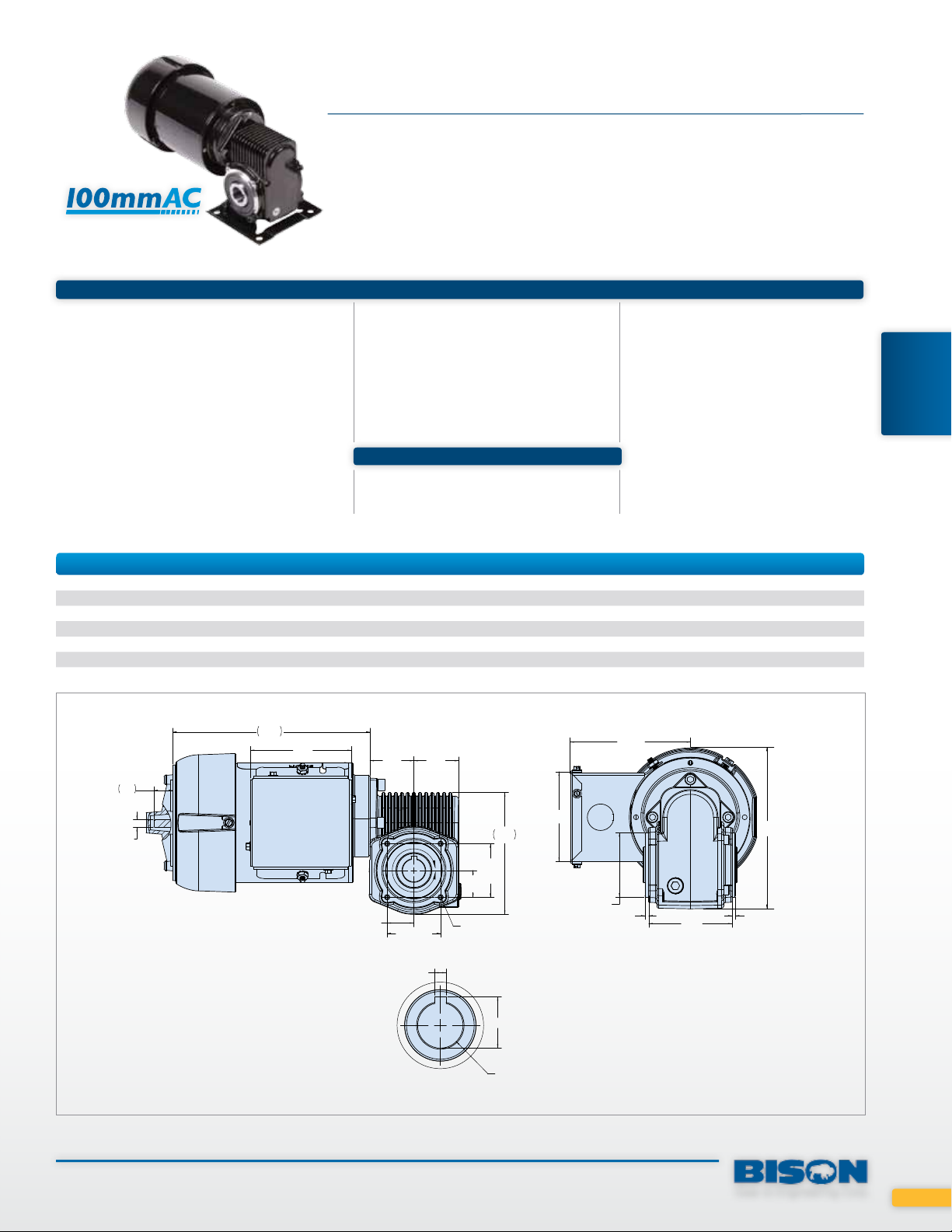
100mm 750 Series Right Angle AC
UP TO 100 IN-LBS CONTINUOUS
For tight-spaces requiring big power, Bison’s 100mmAC (4” dia.),
1/8 HP motors offer larger motor power in 30% less volume.
Motor
Motor Type: Permanent split capacitor
Rotation: Reversible
Bearings: Ball
Insulation: Class B minimum
Enclosure: TEFC
Finish: Gloss black powder coat
Capacitor included
Features
Motors are supplied with mounted
junction box and capacitor, and rear
shaft extension for brake
Additional Information
See pages 56-57 or 86-87 for
additional accessories
Footplate P/N P125-750-1000
Wiring diagram pages 88-91
RIGHT ANGLE
GEARMOTORS
750 Series PSC 115V
Part Number Speed (RPM) Torque (in-lbs) Input HP Gear Ratio Stages OHL Hz Shipping Wt.
026-756-3560 28 100 1/8 60.0 1 300 60 14.75
026-756-3545 37 80 1/8 45.0 1 300 60 14.75
026-756-3530 56 67 1/8 30.0 1 300 60 14.75
026-756-3520 82 43 1/8 20.5 1 300 60 14.75
026-756-3510 164 21 1/8 10.3 1 200 60 14.75
026-756-3505 327 11 1/8 5.2 1 270 60 14.75
750 PSC 115V
.64
ø 0.31
WITH .26
FLAT
6.52
3.33
1.45 1.48
.88
TYP.
1.77 TYP.
.1895
.1875
A
.88
TYP.
#10-32 UNF-2B
X .31 DEEP,
4-PLCS.
1.77
TYP.
3.07
4.03
Ø2.13
TYP.
3.97
.13
2.75
5.32
.13
DETAIL: HOLLOW SHAFT
SCALE 2 : 1
.847
.751
Ø
.750
Gear & Engineering Corp.
53
Specifications
Gearhead
Gearing: Hardened steel worm, forged
bronze gear
Housing: Precision machined die cast
aluminum
Lubrication: Lifetime oil bath, sealed and
RIGHT ANGLE
GEARMOTORS
Bearings: Ball
Shafts: Hardened steel
Mounting: Face or base, any angle
Finish: Gloss black powder coat
o-ringed
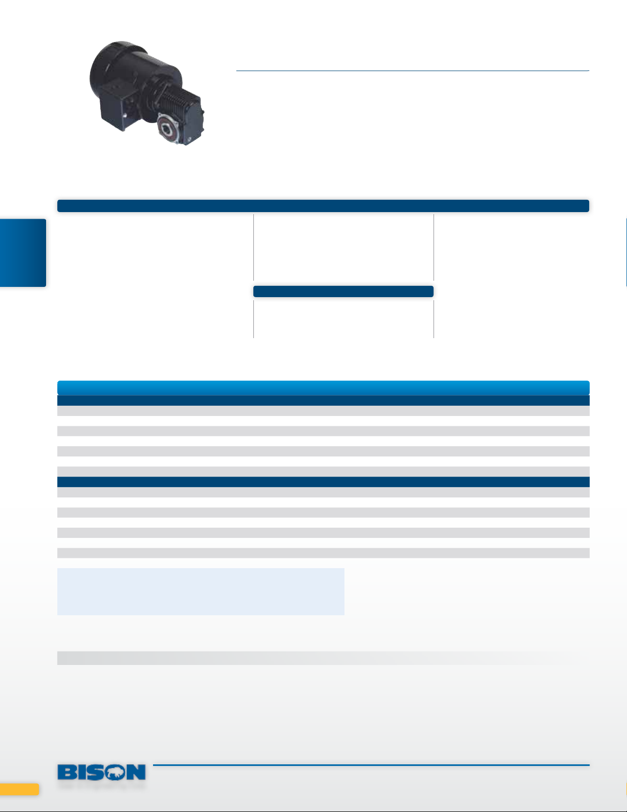
750 Series Right Angle AC
UP TO 130 IN-LBS CONTINUOUS
The 750 Series line of hollow shaft gearmotors allows hundreds
of mounting configurations enabling engineers to optimize their
assemblies. Industry standard mounts are available for drop-in
requirements, and a hollow shaft style is available to use with
optional accessories to meet your specifications.
Additional Information
Wiring diagram pages 88-91
Motor
Motor
Motor Type: Permanent split capacitor
Rotation: Reversible
Bearings: Ball
Insulation: Class B
Enclosure: TEFC
Finish: Gloss black powder coat
Features
Motors are supplied with mounted
junction box and capacitor, and rear
shaft extension for brake.
756 AC PSC 115V/230V
Part Number Speed (RPM) Torque (in lbs.) Input HP Gear Ratio Stages OHL* Amps Hz Shipping Wt.
Hollow / No Footplate
026-756-4460 28 120** 1/4 60.0 1 300 2.40/1.32 60/50 16.75
026-756-4445 36 120** 1/4 45.0 1 300 2.40/1.32 60/50 16.75
026-756-4430 55 130 1/4 30.0 1 300 2.40/1.32 60/50 16.75
026-756-4420 80 108 1/4 20.5 1 300 2.40/1.32 60/50 16.75
026-756-4413 124 76 1/4 1.3 1 300 2.40/1.32 60/50 16.75
026-756-4410 160 62 1/4 10.3 1 300 2.40/1.32 60/50 16.75
026-756-4405 330 30 1/4 5.2 1 270 2.40/1.32 60/50 16.75
Standard Shaft / With Footplate
026-756-4660 28 120** 1/4 60.0 1 300 2.40/1.32 60/50 19.75
026-756-4645 36 120** 1/4 45.0 1 300 2.40/1.32 60/50 19.75
026-756-4630 55 130 1/4 30.0 1 300 2.40/1.32 60/50 19.75
026-756-4620 80 108 1/4 20.5 1 300 2.40/1.32 60/50 19.75
026-756-4613 124 76 1/4 1.3 1 300 2.40/1.32 60/50 19.75
026-756-4610 160 62 1/4 10.3 1 300 2.40/1.33 60/50 19.75
026-756-4605 330 30 1/4 5.2 1 270 2.40/1.33 60/50 19.75
* Maximum overhung load located 2.5” from centerline of gearbox.
** Output torque is gear limited.
*** 60Hz speed shown
Also operable @ 50 Hz @ 5/6 of rated speed
750 Series 3-Phase Inverter Duty 230V
For more specifications see page 64
54
Gear & Engineering Corp.

750 Series Right Angle AC
756 PSC 115V/230V Hollow
0.64
ø0.31
WITH .26
FLAT
(4) #10-32 TAPPED HOLES
EQUALLY SPACED ON 2.50 B.C.
ON BOTH SIDES
6.56 1.45
1.45
1.77
756 PSC 115V/230V Standard Shaft
0.64
6.56 1.45
1.45
1.77
ø0.75
BORE
3/16 SQ.
KEY SEAT
3/16 SQ. KEY
X 1.00 LONG
3.13
2.13 DIA.
0.13
4.03
4.03
2.75
0.13
ø5.53
1.57
1.68
ø5.53
5.80
RIGHT ANGLE
GEARMOTORS
ø0.31
WITH .26
FLAT
0.30 DIA. THRU
HOLES (4) PLACES
3.00
3.75
0.59
OVER
FLAT
3.13
1.34
0.63
DIA.
3.25
1.68
3.25
4.07
Capacitor in junction box
Gear & Engineering Corp.
6.02
55

Inverter Duty AC Gearmotors (continued)
DESIGNED FOR ROBUSTICITY
Specifications
Gearhead
Gearing: AGMA class 9 heat treated steel
Geartrain: Engineered to handle up to 200%
shockloading
Housing: Precision machined die cast
aluminum
Lubrication: Lifetime oil bath
Bearings: Needle and thrust ball, or ball
bearing
Shafts: Precision ground shaft seal diameters
Mounting: All position
Additional Information
650 Series 3-Phase Inverter Duty 230V
Rated Speed
RPM @ 6hz
GEARMOTORS
INVERTER DUTY
Part Number
017-650-0029 6.0 60 90 222 222 148 1/4 28.9 0.75 23
017-650-0070 2.5 25 38 490 490 327 1/4 69.7 0.75 23
017-650-0090 1.7 17 26 722** 722** 442 1/4 89.8 0.75 23
017-650-0214 0.8 7.9 12 650** 650** 650** 1/4 214.5 0.75 23
017-651-0028 6.3 63 95 423 423 282 1/2 27.6 1.60 29
™
Rated Speed
RPM @ 60hz
Rated Speed
RPM @ 90hz
Motor
Motor Type: 230V, 3 phase, 6-90 Hz
Rotation: Reversible
Bearings: Double shielded ball
bearing support
Insulation: Class F (155ºC)
Enclosure: TEFC
Thermostat: Signal type; closed
Wiring diagram pages 88-91
Rated Torque
in-lbs @ 6hz
Rated Torque
In-lbs @ 60hz
Product Line Features
• Global safety recognition:
• Insulation system designed to
• Ambient temperature 0º to 40ºC
• Continuous duty
See pages 86-87 for additional
accessories
Rated Torque
In-lbs @ 90hz
UL, CUL
meet NEMA MG 1 Section 31
Input HPGear
Ratio
Amps
Shipping
Wt.
750 Series 3-Phase Inverter Duty 230V
Part Number
With Mounting Bracket & Output Shaft
027-756-4005 33 330 495 30 30 20 1/4 5.2 0.75 19.8
027-756-4010 16 160 240 58 58 39 1/4 10.3 0.75 19.8
027-756-4013 12.4 124 186 76 76 51 1/4 13.0 0.75 19.8
027-756-4020 8 80 120 108 108 72 1/4 20.5 0.75 19.8
027-756-4030 5.5 55 83 130 130 87 1/4 30.0 0.75 19.8
027-756-4045 3.8 38 57 120** 120** 80** 1/4 45.0 0.75 19.8
027-756-4060 2.8 28 42 100** 100** 67** 1/4 60.0 0.75 19.8
Hollow Shaft & Pilot Mount
027-756-4405 33 330 495 30 30 20 1/4 5.2 0.75 16.8
027-756-4410 16 160 240 58 58 39 1/4 10.3 0.75 16.8
027-756-4413 12.4 124 186 76 76 51 1/4 13.0 0.75 16.8
027-756-4420 8 80 120 108 108 72 1/4 20.5 0.75 16.8
027-756-4430 5.5 55 83 130 130 87 1/4 30.0 0.75 16.8
027-756-4445 3.8 38 57 120** 120** 80** 1/4 45.0 0.75 16.8
027-756-4460 2.8 28 42 100** 100** 67** 1/4 60.0 0.75 16.8
** Output torque is gear limited.
Rated Speed
RPM @ 6hz
Rated Speed
RPM @ 60hz
Rated Speed
RPM @ 90hz
Rated Torque
in-lbs @ 6hz
Rated Torque
In-lbs @ 60hz
Rated Torque
In-lbs @ 90hz
Input HPGear
Ratio
Amps
Shipping
Wt.
64
Gear & Engineering Corp.

650 3-Phase Inverter Duty 1/4 HP
6.56
10.77
0.64
2.00
3/16 SQ. KEY
X 1” LONG
1.71
4.03
0.91
4.78
3.63
ø5.53
ø0.31
WITH .26
FLAT
5.00
DIA.
J-BOX
0.75
DIA.
650 3-Phase Inverter Duty 1/2 HP
J-BOX
14.63
5.61
DIA.
2.00
0.75
DIA.
2.12
750 3-Phase Inverter Duty Standard Shaft 1/4 HP
.88
.64
1.45
1.45
2.12
3/16 SQ. KEY
X 1” LONG
3/16 SQ. KEY
X 1” LONG
3.26
3.13
ø6.76
1.75
1.60
0.44 THREAD DEPTH (6) PLACES
4.78
3.63
4.87
3.92
2.71
6.22
3.59
TAP 1/4-20 UNC-2B
1.71
0.91
2.72
3.59
TAP 1/4-20 UNC-2B
0.44 THREAD DEPTH (6) PLACES
6.22
GEARMOTORS
INVERTER DUTY
0.59
0.30 DIA. THRU
HOLES (4) PLACES
1.50
3.00
3.75
OVER
FLAT
750 3-Phase Inverter Duty Hollow Shaft 1/4 HP
0.64
ø0.31
WITH .26
FLAT
(4) #10-32 TAPPED HOLES
EQUALLY SPACED ON 2.50 B.C.
ON BOTH SIDES
6.56 1.45
1.77
1.45
1.77
ø0.75
BORE
3/16 SQ.
KEY SEAT
3.13
2.13 DIA.
0.63
DIA.
0.13
4.03
3.25
3.75
1.63
2.75
4.94
ø5.53
5.80
1.57
1.68
0.13
Gear & Engineering Corp.
65
 Loading...