

Page 1
—— Instruction Manual ——
VB60
Match Point Volleyball Standards Assembly & Installation
P A R T S L I S T
Item Qty Description Item Qty Description
A 2 VB60S Volleyball Standards E 4 Rope Ratchet Ten sioners (Packaged w / Net)
B 1 Net Tensioning Slider Bar Assembly F 2 Floor Sockets (if applicable)
C 1 Non-Tensioning Slider Bar A ssembly G 1 VB1250K Net
D 2 Height Labels
♦ Inspect all contents prior to installation. Report any missing parts to dealer immediately.
♦ Read all instructions before proceeding.
♦ These systems will adjust from 7’11-5/8” men’s net height to 42” tennis height.
Customer Service
(800) 247-7668
1. If applicable, follow the instructions provided with the Floor Sockets (F) to prepare the court for system
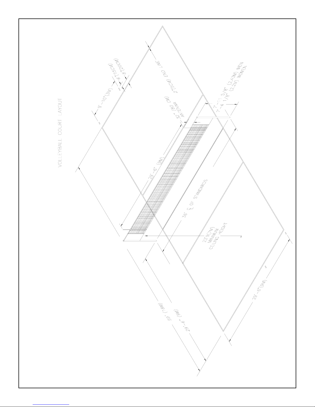
installation, use the diagram on page 3 to locate the Floor Sockets (F) on your court.
2. Place the VB60S Volleyball Standards (A) in the Floor Sockets (F) with the Slider Bars (B) and (C) toward
the inside of the court.
3. Uncoil approximately 24” of the web strap from the winch to allow for net tensioning.
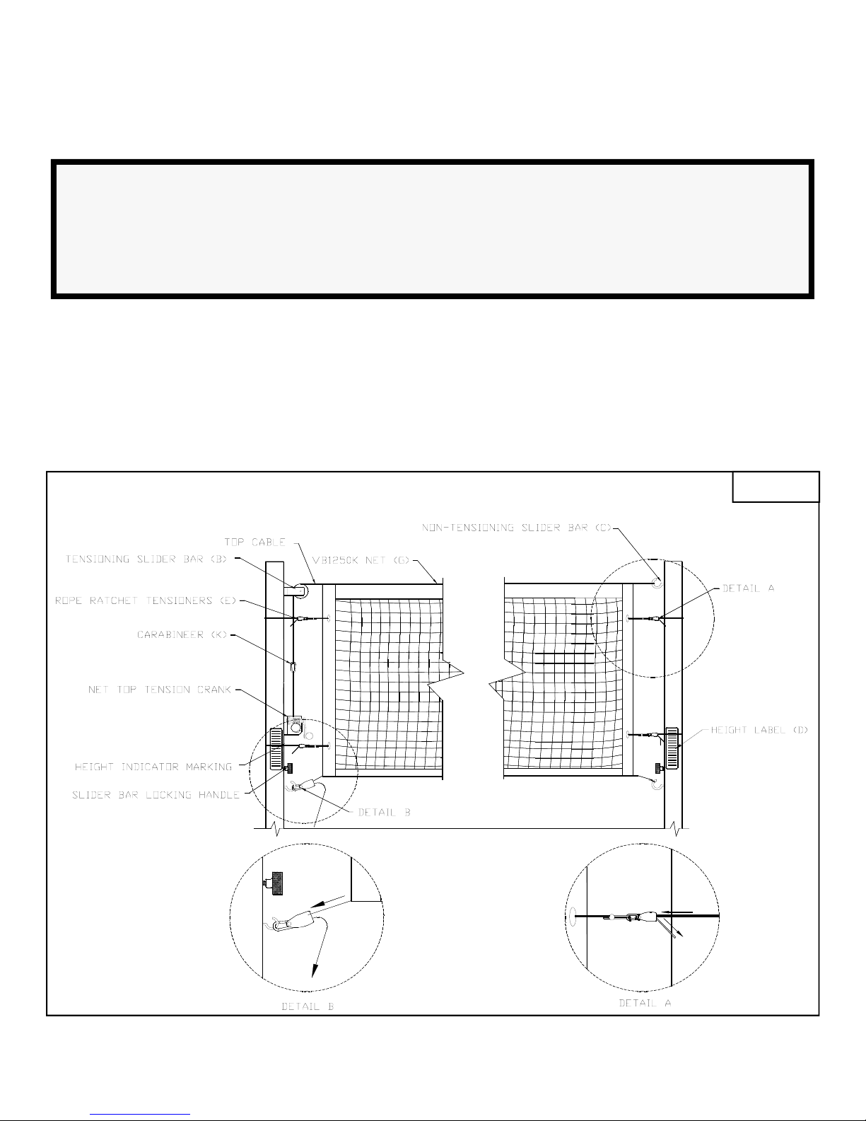
4. Attach the kevlar top rope to the Slider Bars (B) and (C). On the Net Tensioning Slider Bar (B), the rope
will loop over the pulley and attach to the spring clip on the end of the winch strap. On the Non-Tensioning
Slider Bar (C) attach the loop to the hook on the top of the Non-Tensioning Slider Bar (C). See Figure 1.
5. Tension the top rope by tightening the net top tension crank. See Figure 1.
6. Attach the loop on one end of the bottom rope to the hook on the bottom of the slider bar. Attach the other
end of the bottom rope with the spring hook on the rope ratchet. Tension the bottom rope by pulling the
rope through the bottom Rope Ratchet Tensioner (E). See Figure 1.
7. Loop two small Rope Ratchet Tensioners (E) around each standard and through the eyelets on the net side
tapes. Tension the net sides by pulling the end of the ropes. Release the Rope Ratchet Tensioners (E) by
pressing on the release button. Rope Ratchet Tensioners (E) should be rotated close to the pole and behind
the padding to prevent contact with players. See Figure 1.
8. Once the VB1250K Net (G) is attached it must be adjusted to its desired height. Loosen the winch to
release the net tension. Do this before moving the Slider Bars (B) and (C). See Figure 1.
Date: 04/15/09 Rev: 1 B.A. N.J.C. File: \96\VB60.pub Ref#: 960444
1
Page 2
9. After the net tension has been released, loosen the Slider Bar (B) and (C) locking knobs to allow the Slider
Bars (B) and (C) to freely move up and down. Adjust VB1250K Net (G) to desired height. Once the top of
the VB1250K Net (G) is at the desired height, tighten the Slider Bar (B) and (C) locking knobs and net top
tension crank. See Figure 1.
Caution!
The VB1250K net is designed to fit Bison Match Point installation with pole locations between 34’ and 40’
by customizing the length of the top rope. Tie a loop in one end of the top rope at a location that allows
proper tensioning. Do Not cut the excess rope until you are confident you have the correct length. Length
will depend on the distance between the standards. Nets cannot be returned after unwrapping. Call Bison
Customer Service for assistance at #800-247-7668.
10. Once the VB1250K Net (G) is locked and tensioned at the desired height, install the Height Labels (D).
Line up the appropriate line on the Height Label (D) with the machined height indicator mark on the Slider
Bars (B) and (C). Use a credit card or something similar to smooth all air bubbles from Height Labels (D).
11. Install padding and antennas.
Figure 1
2
Page 3
3
 Loading...