

Page 1
WARNING
Do not slide, climb, or
•
play on pole.
Keep organic material
•
away from pole base.
Grass, litter, etc. could
cause corrosion and/or
deterioration.
Check pole system twice
•
a year for signs of corrosion (rust, pitting, and
chipping). Remove rust
and/or loose paint completely and repaint with
exterior enamel paint. If
rust has penetrated
through the steel anywhere, replace pole
immediately.
Check unit before each
•
use for loose hardware,
excessive wear, and
signs of corrosion and
repair before using.
During play, use extreme
•
caution to keep players
face away from the backboard, rim, and net.
OWNER’S MANUAL
Thank you for purchasing a Bison basketball system. We try hard
to ensure that our products are of high quality and free of
manufacturing defects and missing parts. Report any missing
parts or components immediately.
For warranty issues or replacement parts contact:
BISON, INC.
800-247-7668 (ask for parts department)
Wear a mouth guard
•
when playing to avoid
dental injuries.
Please provide model number, and/or part number of the product
and/or part when you call or email. These numbers can be found
on the product packaging, or on the invoice, owners manual or
shipping documents.
When adjusting height,
•
keep hands and fingers
away from moving parts.
Read this manual thoroughly before starting to install your
system. Proceed with each step completely in the order as
During play, do not wear
•
jewelry (rings, watches,
necklaces, etc). Objects
may entangle in net.
REV. 10/10/17
directed.
Page 2

Bill Of Materials
6” SQUARE POLE SYSTEM
Ref. Qty. Description
A 1 Vertical Post
B 1 Main Extension Arm
C 2 Parallel Linkages
D 1 Backboard Assembly
E 2 Spring-Assist Cartridges
F 1 Crank Adjustment Cylinder
G 1 Orange Rim Height Indicator
H 1 5/8” X 6“ Hex Bolt
I 1 5/8” X 8” Hex Bolt
J 2 5/8” Lock Nuts
K 4 5/8” Anchor J-Bolts
L 8 5/8” J-Bolt Hex Nuts
M 4 #4 Rebars
N 1 Anchor Template
O 2 3/4” X 11 1/4” Hex Bolts
P 4 3/4” X 12 1/2” Hex Bolts
Q 6 3/4” Lock Nuts
R 8 3/8” X 1 1/4” Hex Bolts (pre-assembled)
S 8 3/8” Flatwashers (pre-assembled)
T 8 3/8” Lockwashers (pre-assembled)
U 8 3/8” Hex Nuts (pre-assembled)
V 1 Rim Height Sticker
W 4 Plastic and Steel Rim Spacers
Z 8 5/8” Washers
AA 1 Safety Rod
BB 4 5/8” Flanged Hex Nuts
CC 4 3/8” X 3” Hex Bolts
DD 8 3/8” Flatwashers
EE 4 3/8” Lockwashers
FF 2 Screws
GG 1 Rim Cover Plate
HH 1 Net
II 1 Breakaway Rim
REV. 10/10/17
2
Page 3
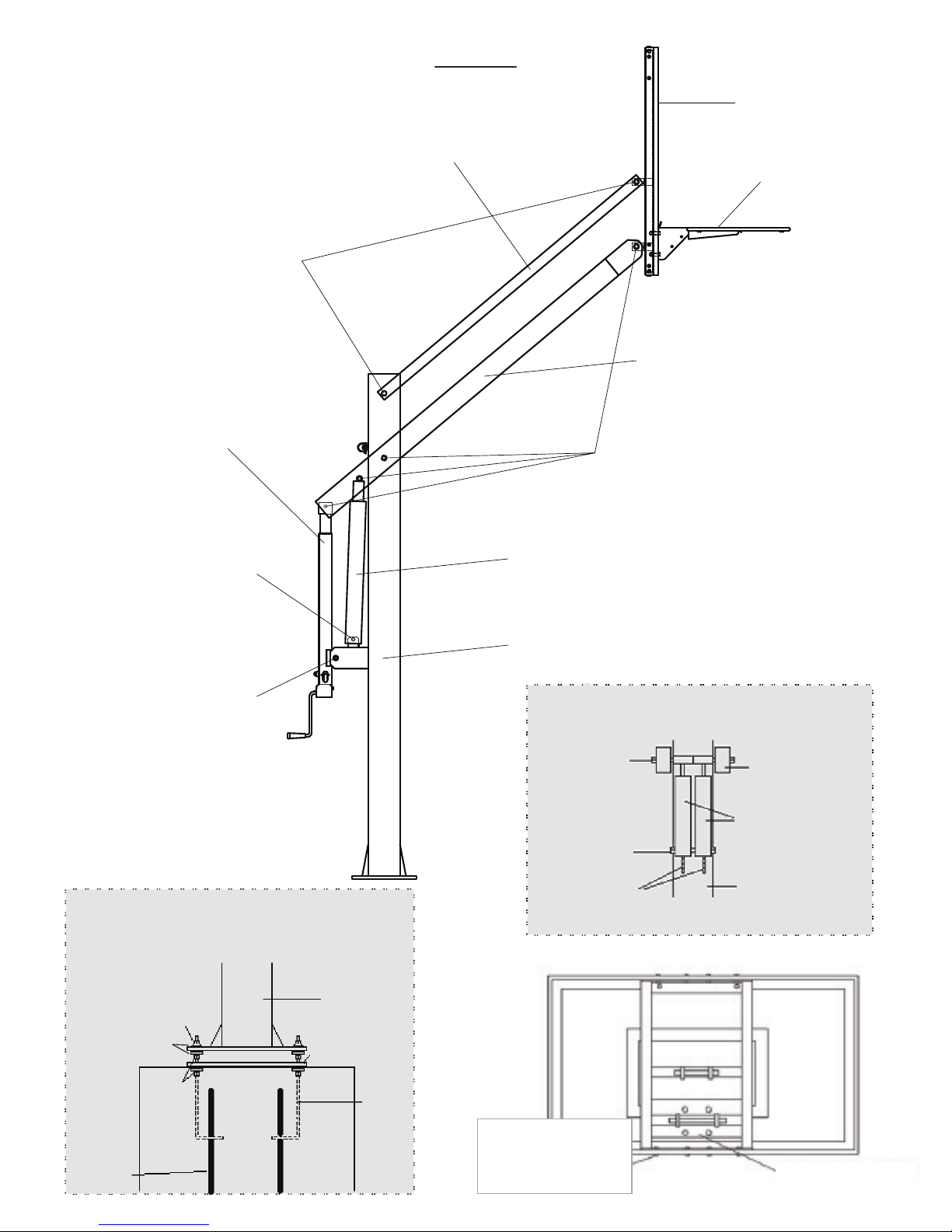
3/4” x 11 1/4” Hex Bolt (O)
with 3/4” Lock Nut (Q)
Figure A
Backboard Assembly (D)
Parallel Linkages (C)
Breakaway Rim (II)
Main Extension Arm (B)
Crank Adjustment Cylinder (F)
5/8” x 8” Hex Bolt (I)
with 5/8” Lock Nut (J)
5/8” x 6” Hex Bolt (H)
with 5/8” Lock Nut (J)
Figure A.2
Vertical Post (A) Mounted to Concrete Footing
3/4” x 12 1/2” Hex Bolt (P)
with 3/4” Lock Nut (Q)
Spring-Assist Cartridges (E)
Vertical Post (A)
Figure A.1 (E)
Rear View of Spring-Assist Cartridges Assembly
3/4" X 12 1/2"
Hex Bolt (P)
Main Extension
Spring-Assist
5/8" X 8"
Hex Bolt (I)
Cartridges (E)
Vertical Post (A)
Welded Tabs
Arm (B)
5/8” J-Bolt
Flanged Hex
Nut With Built-In
Washer (BB)
5/8” Washers (Z)
Anchor Template
(N)
5/8”
J-Bolt
Hex
Nuts
#4 Rebars
(M)
REV. 10/10/17
(L)
Concrete
Pier
Vertical
Post (A)
5/8”
Anchor
J-Bolts
(K)
3/8" X 1 1/4" Hex Bolt (R)
3/8" Flat washer (S)
3/8" Lock washer (T)
3/8" Hex Nut (U)
Pre-Assembled
Backboard Assembly (D)
3
Page 4
SAFETY INSTRUCTIONS
IMPORTANT
It is the responsibility of purchaser to ensure that
all installers and players fully comply with the
detailed instructions set forth in this product
installation manual. Product assembly should be
carried out exactly as instructed and owner
supervision of use and installation is required to
prevent risk of product malfunction or risk injury.
All tools used to assemble this product
should be used in compliance with
manufacturer’s guidelines.
Installation of this product will require heavy
lifting and bending. Any person that is not
capable of such activity should not
participate in the installation of this product.
If using a ladder during assemble, use
extreme caution and refer to the warnings
and cautions on the ladder.
Due to the size and weight of this product,
we recommend at least (4) competent adults
are present.
Before digging the hole for the anchor
system, please call 811 to ensure that all
underground utilities area safe distance
away from the anchor system.
Make sure there are no overhead power
lines within a 25 foot radius of the basketball
system.
All parts and components necessary to
complete proper installation are included
within this product. Do not use parts not
included with our system. Failure to follow
this requirement could cause product
malfunction and will void warranty of this
product.
Keep all organic materials away from parts
and components to avoid corrosion.
Please use caution when performing this
basketball hoop.
Do not climb on any part of the basketball
system as it was not intended for this activity.
Do not use the basketball system as a lift or to
hoist anything.
Players should wear protective mouth guard
during play to avoid dental injury.
Players should refrain from wearing any
jewelry that could potenially get caught in the
rim or net.
Only hang on the rim momentarily to regain
your balance. Release the rim as soon as
possible.
Do not allow children to adjust basketball
system.
Check the basketball system on a regular
basis to ensure that there are no signs of
deterioration or corrosion, loose hardware, or
damaged parts. If you see any signs of
damage perform maintenance or contact us.
For maintenance repairs please contact a
professional.
Failure to follow these safety instructions
could result in product malfunction, serious
injury, or even death.
Bison retains the right to modify this
document at anytime without notice or
obligation.
Keep this installation manual as a
reference for your safety and the safety
of those playing on the basketball
system. Additional copies of these
safety instructions are available at
bisoninc.com/instructions-videos.
REV. 10/10/17
4
Page 5

INSTALLATION OVERVIEW
In order to have the safest, most enjoyable and longest use of your basketball system,
please note and heed the following:
1) Prior to goal assembly, call utility services for location of
underground utility lines before you dig.
2) Immediately unpack and inspect all components. Cross check
against bill of materials.
3) Assembly is a two step process.
STEP 1
Day 1: Complete Anchor System Installation
Day 2: Allow concrete to cure.
Day 3: Allow concrete to cure.
Day 4: Allow concrete to cure.
STEP 2
Day 5: Complete assembly
REV. 10/10/17
5
Page 6
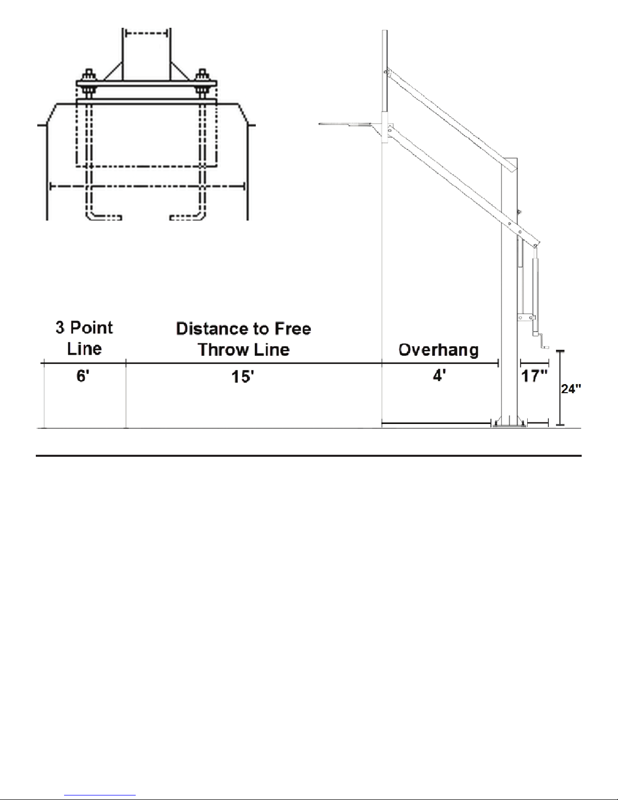
6”
12”
24”
3’10” 15”
REQUIRED TOOLS
• Post Hole Digger
• Shovel
• Wheelbarrow or Cement Mixer
• (20-25) 80 lbs. bags of concrete OR
(27-32) 60 lbs. bags of concrete
• Garden Hose
• Trowel
• Level
• Tape Measure
• Knife
• (2) Large Crescent Wrenches (main bolts and pier)
• (2) 9/16” Wrenches (rim hardware)
• Broom Stick to Settle Concrete
REV. 10/10/17
6
Page 7
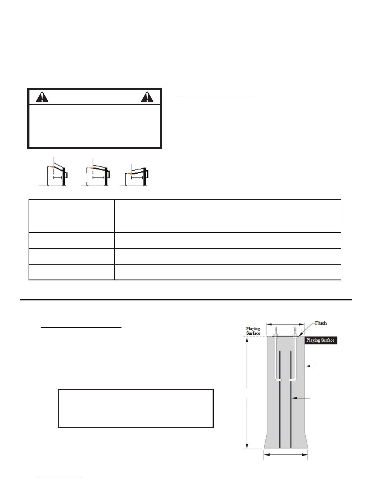
STEP 1
ANCHOR SYSTEM INSTALLATION INSTRUCTIONS
1) Installation Location
WARNING
Before digging the hole for this pole, check
for buried power, gas, water, and
telecommunication lines! Failure to do so
could result in serious or fatal injury!
Contact your local utility company if unsure.
Choose the proper location to dig for the
concrete footing. Use the drawing on the
previous page to help you locate. When
choosing the exact position to dig, make sure to
maximize the amount of playing surface while
minimizing possible driveway obstruction. Pole
10’
48” 66” 65”
8’
6’
should be as close to the edge of the concrete as
possible to reduce the chance of injury.
Rim Height Distance from the face of the backboard to the front of
the Vertical Post (A)
6' 65"
8' 66"
10' 48"
2) Digging Footing Hole
Dig hole 48” deep and 24” square. Be sure to
bell out the bottom of the hole 28” to give added
stability to the footing.
*NOTE: If you live in an extremely cold
climate where the frost line is commonly
below 48” it is advisable to dig to normal
frost line.
REV. 10/10/17
48” *
24” Diameter
28” Diameter
Concrete
(20-25) 80 lbs. bags
Rebar
(4 Pieces)
7
Page 8
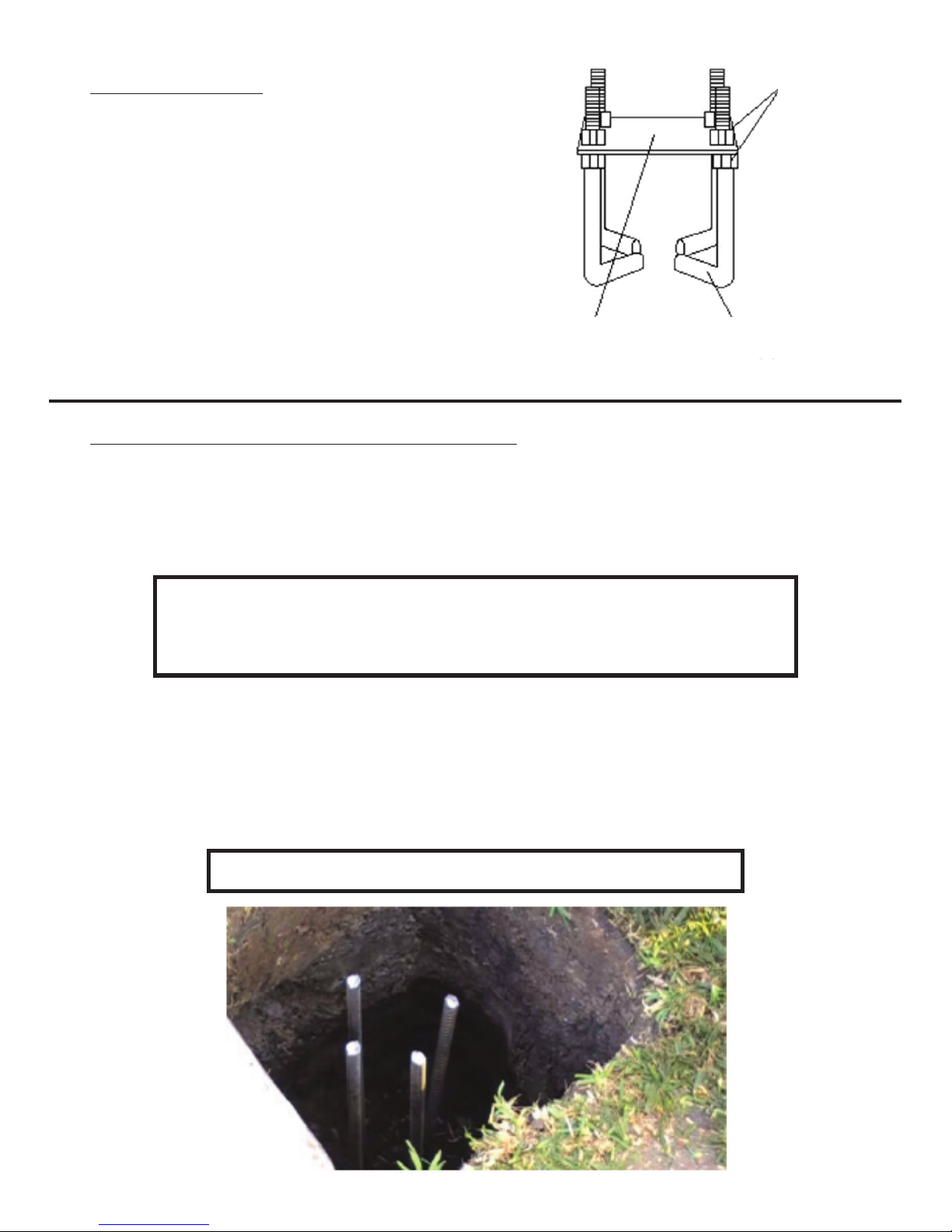
3) Anchor Assembly
Thread one 5/8” Hex Nut (L) to the bottom on
each 5/8” Anchor J-bolt (K). Place these
J-bolts through the holes on the Anchor
Template (N) and install 5/8” J-Bolt Hex Nuts
(L) on top and tighten.The bottom of the
J-bolts should be positioned as shown.
5/8” J-Bolt
Hex Nuts (L)
Anchor Template
(N)
5/8” Anchor
J-Bolts (K)
4) Pouring Concrete and Setting Footing Base
For this step you will need: level, broomstick and tape measure. The 48" x 24"
anchor footing will require a little over a 1/2 yard of 3000 psi concrete (20-25 80
pound sacks of premix concrete). More will be needed if you dig a larger hole.
NOTE: Make certain that you have enough concrete to finish
the job. Allowing a portion to dry while you purchase more
concrete will weaken the footing.
Mix (20-25) 80 lbs. bags of concrete in wheelbarrow or cement mixer and pour
in pre-dug hole about half full. Agitate concrete with shovel or broomstick to
ensure proper fill. Place (4) Pieces of #4 Rebar (M) in the middle of the hole
about 8” apart to create a square in the middle of the hole. Top of rebar needs
to be approximately 3” from the top of the hole.
NOTE: It is better to mix concrete slightly too wet than too dry.
REV. 10/10/17
8
Page 9
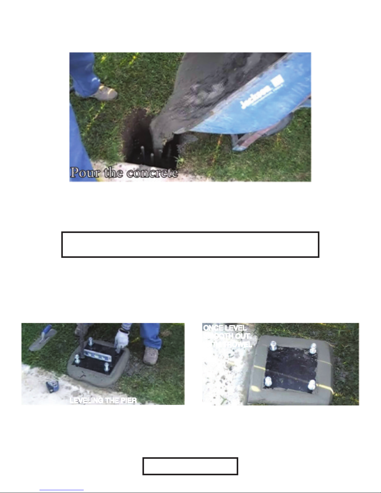
Pour the remaining concrete into the hole until completely full and coming out of
the top. Using a trowel, smooth the concrete to allow draining away from the
pole.
Place the assembled anchor system in the hole to the point where the bottom of
the Anchor Template (N) rests on the top of the finished concrete.
NOTE: The (4) 5/8” J-Bolt Hex Nuts (L) on the bottom of the Anchor
Template (N) will remain embedded into the concrete after the footing cures.
Use a level to ensure that the Anchor Template (N) is level in all directions.
Additionally, the center line of the 5/8” Anchor J-Bolts (K) must be parallel with
the edge of the playing surface to ensure that the backboard will be properly
positioned.
ONCE LEVEL
ONCE LEVEL
ONCE LEVEL
ONCE LEVEL
SMOOTH OUT
SMOOTH OUT
SMOOTH OUT
SMOOTH OUT
WITH TROWEL
WITH TROWEL
WITH TROWEL
WITH TROWEL
LEVELING THE PIERLEVELING THE PIERLEVELING THE PIER
LEVELING THE PIER
Once completely smooth let the concrete cure. This can take up to a week
depending on the weather conditions. Consult the instructions on the concrete
bag for curing times and directions.
REV. 10/10/17
STEP 1 COMPLETE!
9
Page 10
STEP 2
ASSEMBLY INSTRUCTIONS
CAUTION
FOUR PEOPLE ARE RECOMMENDED FOR
SAFE INSTALLATION OF THE SYSTEM
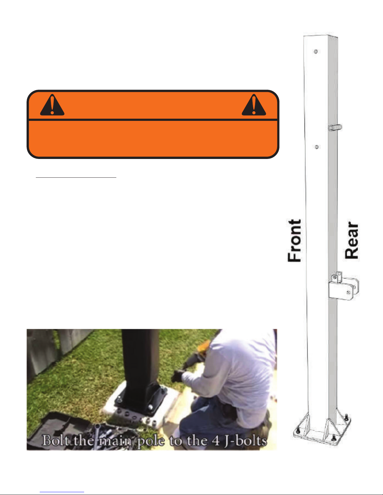
5) Main Pole Assembly
Remove the top four 5/8” J-Bolt Hex Nuts (L) from the 5/8”
Anchor J-Bolts (K). Remove Anchor Template (N). Install
(4) additional 5/8” J-Bolt Hex Nuts (L) on the 5/8” Anchor
J-Bolts (K) and level.
Install (4) 5/8” Washers (Z) on top of the 5/8” J-Bolt Hex
Nuts (L). Remove the pole padding from the Vertical Post
(A). Install the Verical Post (A) onto the J-Bolts. Install (4)
5/8” Washers (Z) on top of the pole base plate. Install (4)
Flanged Hex Nuts (BB) to top of the anchor bolts and
tighten. Make sure that base plate is parallel to playing
surface.
REV. 10/10/17
10
Page 11
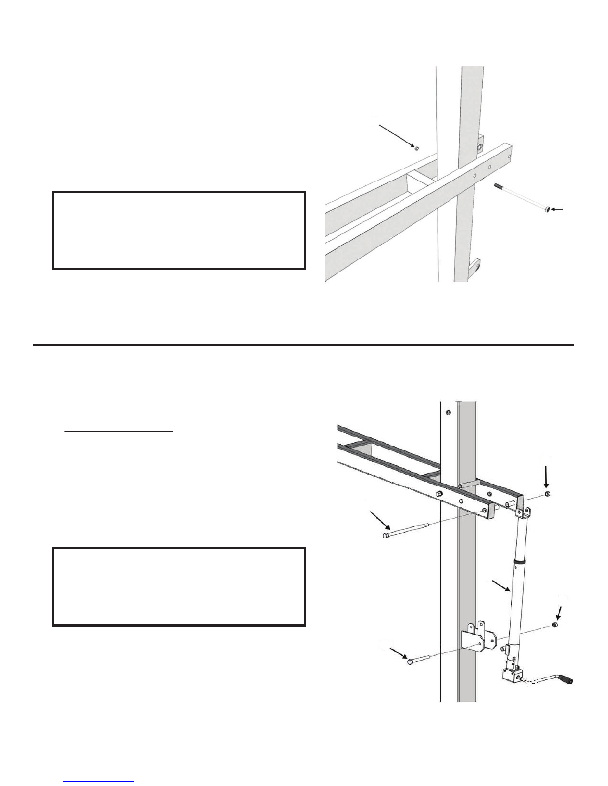
6) Main Extension Arm Assembly
Slide the Main Extension Arm (B) over the top of
the Vertical Post (A) and attach to the lower
pivot tube with a 3/4” X 12 1/2” Hex Bolt (P) and
a 3/4” Lock Nut (Q).
(Q)
NOTE: Tighten the lock nut down and
then back off a 1/4 turn to allow the
joint to pivot when adjusting the
system up and down.
7) Actuator Assembly
Attach the Crank Adjustment Cylinder (F) using
a 3/4” X 12 1/2” Hex Bolt (P) and 3/4” Lock Nut
(P)
(Q)
(Q) at the top and 5/8” X 6” Hex Bolt (H) with
5/8” Lock Nut (J) at the bottom.
NOTE: Tighten the lock nuts down
and then back off a 1/4 turn to allow
the joint to pivot when adjusting the
system up and down.
REV. 10/10/17
(P)
(F)
(J)
(H)
11
Page 12
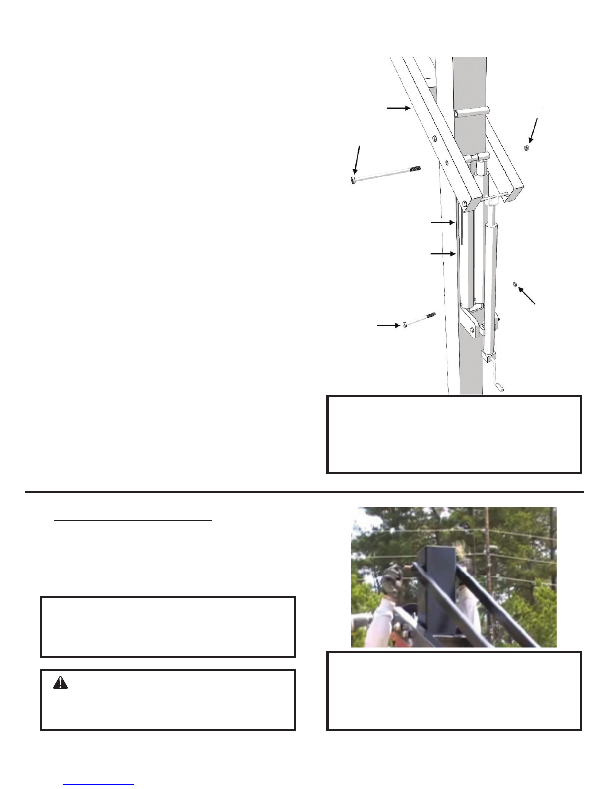
8) Spring Assist Assembly
Attach Spring-Assist Cartridges (E) to the
Main Extension Arm (B) using a 3/4” X 12 1/2”
Hex Bolt (P) and 3/4” Lock Nut (Q). The
Orange Rim Height Indicator (G) must slide
onto the 3/4“ x 12 1/2” Hex Bolt (P) on
whichever side you wish to install the height
indicator label shown in instruction #14. In
(P)
(B)
(Q)
order to attach both Spring-Assist Cartridges
(E) at the bottom, lower the open end of each
Spring-Assist Cartridges (E) down over the
top of each welded tab as shown in the
diagram. You will use the Crank Adjustment
Cylinder to help align the lower mounting
holes. Use the 5/8” X 8” Hex Bolt (I) and 5/8”
Lock Nut (J) to attach them to the welded
tabs. You may need to turn or rotate the
Spring-Assist Cartridges (E) to line up holes.
The Rim Height Indicator (G) should hang
freely along the ouside of one of the
Spring-Assist Cartridges (E). Next, remove
and discard the plastic spring assist spacer
from Spring-Assist Cartridges (E).
(G)
(E)
(J)
(I)
NOTE: Tighten the lock nuts down
and then back off a 1/4 turn to allow
the joint to pivot when adjusting the
system up and down.
9) Upper Linkage Assembly
Attach Parallel Linkages (C) to Vertical
Post (A) with a 3/4” X 11 1/4” Hex Bolt (O)
and a 3/4” Lock Nut (Q).
NOTE: It does not matter which end
of the parallel link you attach to the
vertical post.
CAUTION: Injury may occur if
linkages are allowed to fall from main
arm during assembly.
REV. 10/10/17
NOTE: Tighten the lock nuts down
and then back off a 1/4 turn to allow
the joint to pivot when adjusting the
system up and down.
12
Page 13
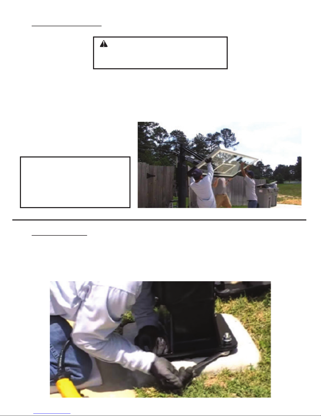
10) Backboard Assembly
CAUTION: ATTACHING THE
BACKBOARD REQUIRES AT
LEAST FOUR CAPABLE ADULTS.
Mount the lower Backboard Assembly (D) mounting tube first to the Main
Extension Arm (B) using one 3/4” X 12 1/2” Hex Bolt (P) and one 3/4” Lock Nut
(Q). Next, attach the upper Backboard Assembly (D) mounting tube to the Parallel
Linkages (C) using one 3/4” x 11 1/4” Hex Bolt (O) and one 3/4” Lock Nut (Q).
NOTE: Tighten the lock nuts
down and then back off a 1/4
turn to allow the joint to pivot
when adjusting the system up
and down.
11) Level Backboard
Check face and top of backboard to see if it is level and plumb. If not, correct by
adjusting the 5/8” J-Bolt Hex Nuts (L) located both below and above the Vertical
Post (A) base plate.
REV. 10/10/17
13
Page 14
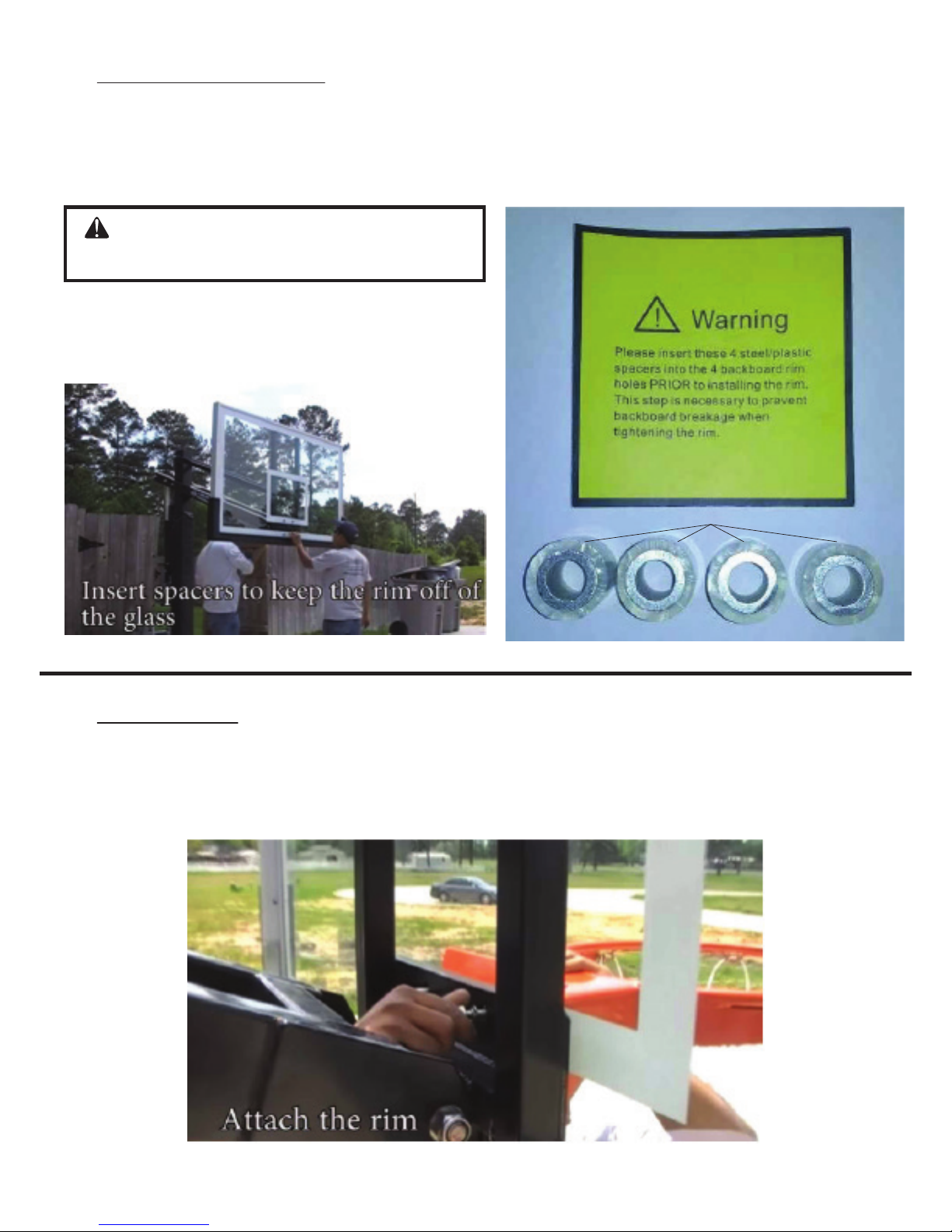
12) Rim Spacers Assembly
Prior to installing the rim on to the backboard assembly, insert (4) Plastic and
Steel Rim Spacers (W) into four holes in the backboard. This is very important to
prevent backboard breakage.
CAUTION: Do not proceed with
rim installation without these spacers
(W)
13) Rim Assembly
Mount the Breakaway Rim (II) to the Backboard Assembly (D) using the hardware
supplied in the rim box (CC, DD, EE).
REV. 10/10/17
14
Page 15
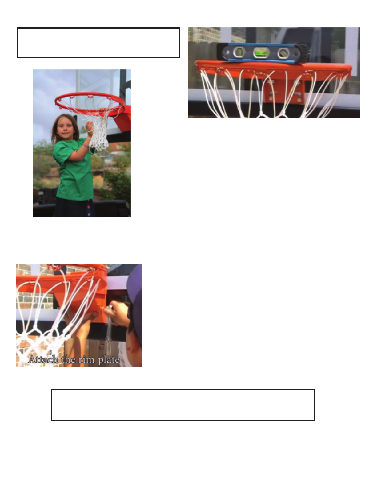
NOTE: Use a level to make sure rim is
level side to side before tightening nuts.
Attach the Net (HH) to the Breakaway Rim (II).
Using (2) Screws (FF) attach the Rim Cover Plate (GG) to the Breakaway Rim (II). The Rim
Cover Plate (GG) covers the springs in the Breakaway Rim (II) as shown below.
Make sure all nuts on the system have been tightened.
NOTE: Do not over tighten. If unit is excessively difficult to crank up
and down, the Lock Nuts that secure all moving parts are too tight.
If not already done, remove the spring assist spacer. Cut off the spring assist spacer
that is attached to the Spring-Assist Cartridges (E) using a sharp knife.
REV. 10/10/17
15
Page 16
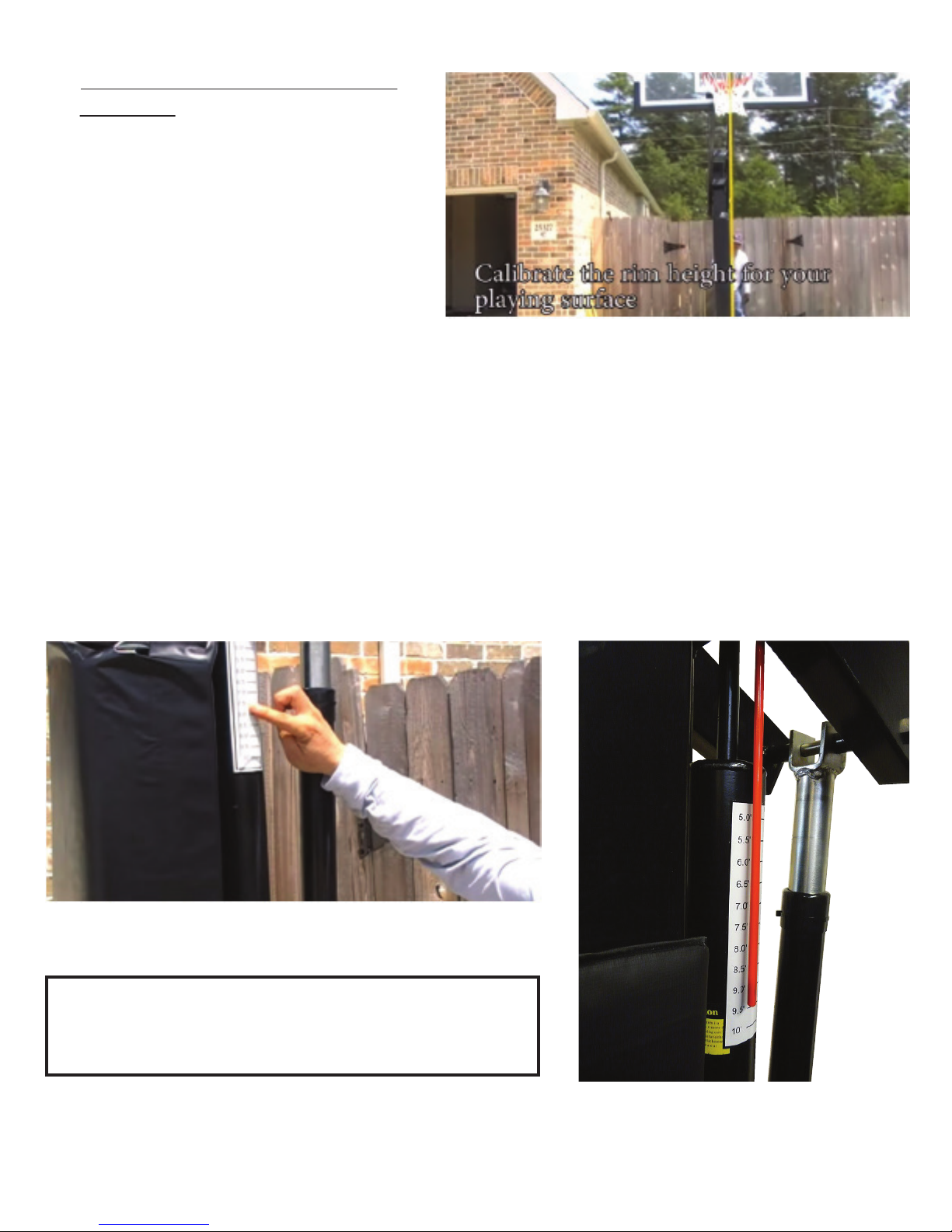
14) Rim Height Indicator and Sticker
Assembly
To apply the Rim Height Sticker (V),
first use a tape measure to raise the
top of the rim up to exactly 10’ from
the playing surface.
Use a pencil to make a mark on the Spring-Assist Cartridges (E) where the bottom
of the Orange Rim Height Indicator (G) stops. Then, peel and apply sticker to the
outside of Spring-Assist Cartridges (E) lining up the pencil mark with the 10’ mark on
the sticker. See image below for a diagram of a completed height indicator
assembly.
NOTE: It is advisable to wait up to two weeks to
allow the anchor footing to fully cure before
aggressive play.
REV. 10/10/17
16
Page 17
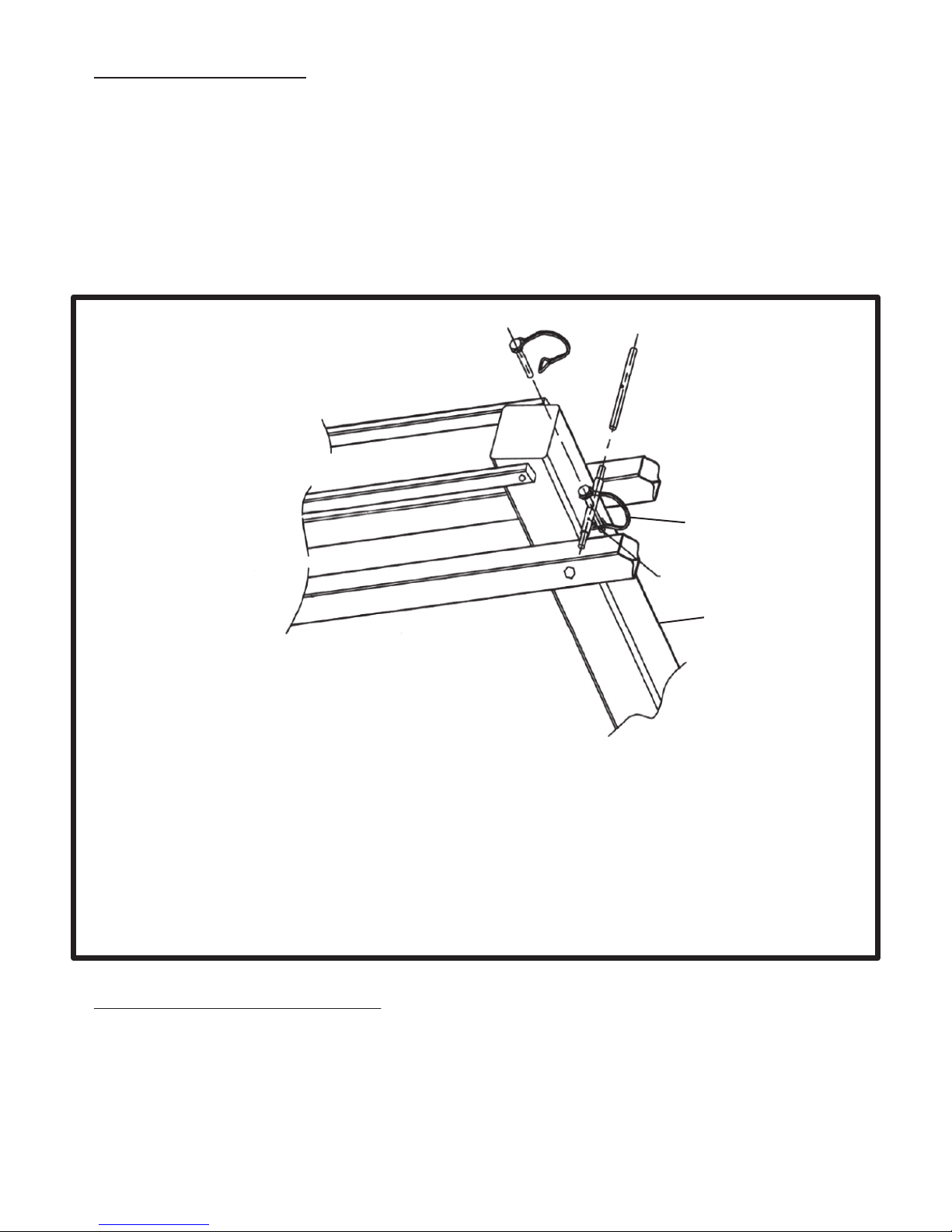
15) Safety Pin Installation
It is advisable to restrict height adjustment from 10’ to 7’6” to ensure safe play.
Insert the Safety Rod (AA) into the tube on the back of the Vertical Post (A).
If a lower rim height is needed for abnormally low play, remove the Safety Rod
(AA) before adjusting any lower than 7’6”.
(AA)
(A)
1) Insert the Safety Rod (AA) into tube on the back of the
Vertical Post (A).
2) Insert the locking pin through the hole in the tube and the hole in
the Safety Rod (AA).
3) Lock the locking pin as shown in figure above.
16) Protective Padding Assembly
Reattach padding. Attach using the Velcro on the back of the padding to secure it
to the system.
REV. 10/10/17
17
Page 18

17) Maintenance
Like any piece of equipment proper maintenance is required. Several factors such as
the environment, organic materials, herbicides, pesticides, excessive use or misuse
can eventually cause the basketball system to require maintenance. Failure to do so
could result in system failure, property damage, or even personal injury or death.
1) All organic materials should be kept away from the system at all times. This will
alleviate any chance of rust penetrating the powder coated finish and causing
structural damage.
Examples: grass clippings, moisture, garbage, dirt, etc.
2) If you see any signs of rust on the system remove the loose paint, sand the area
with a medium grit sandpaper and apply outdoor enamel to the affected area.
3) To clean the backboard use a 100% cotton soft cloth with mild dishwashing liquid
for soap and luke warm water. Rinse backboard with lukewarm water. Wash gently
with a 100% cotton soft cloth, lukewarm water and mild soap. Do not scrub. Rinse
backboard with lukewarm water again. Dry with 100% cotton soft cloth.
4) Never adjust the rim below 5’ or over 10’. Adjustments of the goal should be done
under adult supervision. When attempting to slam dunk you should always wear a
mouth guard to avoid dental injury. If Safety Rod and Pin (AA) is installed do not
adjust the system below 7’ 6”. If a lower height is desired remove the Safety Pin
(AA) and continue to adjust downward.
5) If installed in a public area it is suggested to lock the adjustment mechanism. You
can purchase a padlock at any hardware store.
REV. 10/10/17
18
 Loading...