

Page 1
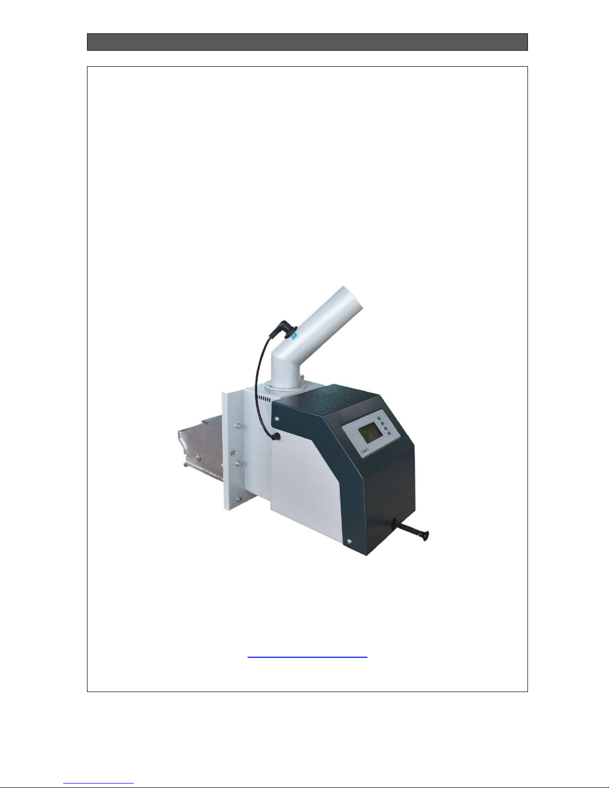
INSTALLATION, OPERATION AND MAINTENANCE MANUAL
Bisolid GP xx_B hc> 20 July 2017 OM-BSGPHCV02/07/2017/EN
MANUAL
FOR INSTALLATION, OPERATION AND MAINTENANCE OF PELLET
BURNER SERIES BISOLID GP XX B HC>
http://www.bisolid.eu
Page 2

INSTALLATION, OPERATION AND MAINTENANCE MANUAL
Bisolid GP xx_B hc> . OM-BSGPHCV02/07/2017/EN 2
CONTENT page.
1. IMPORTANT INFORMATION ABOUT THE PELLET BURNER OPERATION 3
1.1. SAFETY INSTRUCTIONS 3
1.2. PURPOSE OF THE PELLET BURNER 5
1.3. FUEL 6
1.4. PELLET BURNER DESCRIPTION 7
1.5. PELLET BURNER OVERALL DIMENSIONS 8
1.6. PELLET BURNER TECHNICAL DATA 9
2. INTRODUCTION 10
2.1. PELLET BURNER GENERAL REQUIREMENTS 10
2.2. ENSURING PEOPLE AND EQUIPMENT SAFETY 11
3. OPERATION INSTRUCTIONS 11
3.1. OPERATION OF PELLET BURNER SERIES BISOLID GP XX_B HC> 11
3.2. SAFE OPERATION OF THE PELLET BURNER 12
4. PELLET BURNER INITIALIZATION FOR OPERATION 13
4.1. PELLET BURNER CHECK-UPS BEFORE INITIALIZATION FOR OPERATION 13
4.2. JOINT OPERATION OF PELLET BURNER AND SOLID FUEL BOILER 13
5. OPERATION AND CONTROL OF PELLET BURNER FROM BISOLID GP XX_B HC> SERIES 14
5.1. DESIGNATION OF THE PELLET BURNER CONTROLLER 14
5.2. OPERATION OF THE PELLET BURNER CONTROLLER 14
5.3. STARTING THE PELLET BURNER 14
5.4. SWITCHING OFF THE PELLET BURNER 15
5.5. BURNER CONTROLL THROUGH GSM MODULE (OPTION) 15
5.6. METHODS FOR FORMING THE DESIRED TEMPERATURE 15
5.6.1. MANUAL DETERMINATION OF THE HEATING WATER ASSIGNMENT (ТB SET) 15
5.6.2. DETERMINATION OF THE HEATING WATER ASSIGNMENT ON OUTSIDE TEMPERATURE
THROUGH SENSOR PT1000 15
5.6.3. DETERMINATION OF THE HEATING WATER ASSIGNMENT ON ROOM TEMPERATURE
THROUGH SENSOR PT1000 IN THE ROOM 16
5.6.4. DETERMINATION OF THE ASSIGNMENT FROM ROOM THERMO REGULATOR 16
5.7. TEMPERATURE AND SECURITY RESTRICTIONS 17
5.8. FRONT CONTROL PANEL OF THE PELLET BURNER 17
5.9. OPERATION (FUNCTIONING) OF THE PELLET BURNER 18
CAN BE SWITCHED ON ONLY WHEN THERE IS START COMMAND ON BOTH PLACES. 19
5.9.1. USER’S SETTINGS 19
5.9.2. WEEKLY TIMER 19
5.9.3. INFORMATION ON ALARM MESSAGES 20
5.10. SERVICE SETTINGS 21
5.10.1 COMMON SETTINGS 21
5.10.2 IGNITION SETTINGS 22
5.10.3 SETTINGS IN BURN MODE 22
5.10.4 SETTINGS IN STOP MODE 23
5.11. SMS COMMANDS 23
5.12. CONNECTING THE PELLET BURNER TO THE ELECTRICAL POWER SUPPLY 24
5.13. WARRANTY AND WARRANTY CONDITIONS 25
5.14. PELLET BURNER PACKAGE KIT AT DELIVERY 25
5.15. PELLET BURNER CLEANING 25
5.16. PELLET BURNER SERVICING 27
5.16.1. BASIC AND PERIODIC CLEANING OF PELLET BURNER 28
6. INSTALLATION INSTRUCTIONS FOR PELLET BURNER SERIES BISOLID GP XX_B HC> 29
6.1. PELLET BURNER INSTALLATION – COMMON INFORMATION 29
6.2. CHOOSING A PELLET BURNER 29
6.3. POSITIONING OF THE PELLET BURNER 30
6.4. TRANSPORTATION AND STORAGE 31
7. PELLET BURNER WIRING DIAGRAM 32
8. TROUBLESHOOTING 33
Page 3

INSTALLATION, OPERATION AND MAINTENANCE MANUAL
Bisolid GP xx_B hc> . OM-BSGPHCV02/07/2017/EN 3
1.
IMPORTANT INFORMATION ABOUT THE PELLET
BURNER OPERATION
Dear Bisolid GP xx_B hc> pellet burner owners,
We would like to congratulate you for your new pellet burner. By purchasing this quality
product from the manufacturer you have chosen a system that ensures higher comfort level
and optimized fuel consumption in environmentally protecting and natural resource saving
way. Your pellet burner is manufactured under strict ISO 9001 standards.
On the next pages we have introduced specific information and important advices about the
system operation, its functions and methods of maintenance. Please pay special attention to
this manual. Good knowledge of this document content will give you the pleasure of long-term
and trouble-free operation of the pellet burner.
1.1.
SAFETY INSTRUCTIONS
The wood pellet burner from series Bisolid GP xx_B hc> and its accessories correspond to all
applicable directions for safety techniques. Your wood pellet burner and all of its accessories
operate under variable electricity 230 VAC. Improper electrical installation or repair may
endanger user’s life from electrical shock. Installation works must be performed only by
qualified technicians.
This manual is intended for authorized service specialists only. It is important to know that:
Works on the heating installation should be performed only by technicians who had
acquired such rights by law.
Works on the electrical installation should be performed by qualified electricians only.
Initial operation start up including installation visual checks, adjustments and starting
must be performed by the manufacturer authorized personal.
Legal provisions
While operating with the appliance please observe:
Legal provisions for safety techniques.
Legal provisions for environment protection.
Provisions for proper installation.
Applicable provisions of the European community.
Safety instructions
Danger
Please observe these safety instructions in order to prevent the people from
risks and harms, as well as damage to properties and environment.
Safety instructions explanation.
Please pay attention to the following symbols in this manual:
Page 4
INSTALLATION, OPERATION AND MAINTENANCE MANUAL
Bisolid GP xx_B hc> . OM-BSGPHCV02/07/2017/EN 4
Danger
This symbol warns the user about health risks
Warning
This symbol warns the user about possible risks and harms to properties and
environment.
Information
This symbol presents text with additional information for the user.
Works or activities for setting the appliance in proper technical working order
The current manual for operation, installation and maintenance uses notation
Bisolid GP xx_B hc> includes the model of pellet burner modification GP
20_B18 hc>, GP 25_B hc> and GP 32_B hc>.
Repairs of constructional elements which functions are related to the technical
safety may compromise the safely operation of the installation. Damaged or
faulty elements must be replaced with genuine spare parts provided by the
manufacturer.
After carefully reading of the installation and operation manual, you will acquire
all necessary information about design, controls and safety operation of the
pellet burner. After unpacking the pellet burner please check its completeness
and delivered elements. Check whether the pellet burner size corresponds to
the desired designation.
If any failures or troubles occur the pellet burner must be led out from operation and removing
of the faults/troubles must be provided by specialized company. For proper functioning, safe
and long-term operation of the pellet burner, a regular check ups and prophylaxis must be
performed at least once per year. Such technical care guarantees your investment.
Repairs should be performed only with genuine spare parts. In case of faults or troubles
caused by unqualified installation, non-compliance with the requirements or the operation
manual, the manufacturer company is not responsible and does not provide warranty for the
product.
Page 5

INSTALLATION, OPERATION AND MAINTENANCE MANUAL
Bisolid GP xx_B hc> . OM-BSGPHCV02/07/2017/EN 5
1.2. PURPOSE OF THE PELLET BURNER
Type designation of pellet burner’s series: GP 20_B 18 hc>
Example GP 20_B 18 hc
Pellet burner trade name
Nominal heating output *, kW
Pellet burner with hand frontal cleaning
* Similar to other models of pellet burners GP 25_B hc> and GP 32_B hc>.
The purpose of the fully automated pellet burner series Bisolid GP xx_B hc> in combination
with hot water solid fuel boilers Bisolid is for heating domestic housings with small and
medium sizes. The pellet burner is very good solution for housings heated with Bisolid wood
logs boilers, because the installation of the pellet burner to such hot water boiler can be
performed by standard assembly kit.
The burner’s main advantages as automatic ignition, automatic adjusting of the heating output
(in optimization mode for operation with room thermostat) and its multifunction control panel
are making its usage easy and comfortable during the heating season
The burners from series Bisolid GP xx_B hc> is designated to utilize wood pellets according to
standard EN ISO 17225-2:2014, class A1 and its corresponding quality characteristics. The
fuel and the air are mixed in the burner by a precisely controlled method and this is the reason
for ecological burning and high efficiency.
The pellet burner’s series Bisolid xx_B hc> can be mounted to the hot water
solid fuel boilers with sufficiently high efficiency.
The necessary minimum time for technical servicing of the Bisolid GP xx_B hc> pellet burner,
depending on the used wood pellets characteristic and quality, is once per week.
The optimum functionality of the appliance depends either on the professionally designed
heating installation or its precise handling.
The main advantages of the pellet burner series Bisolid GP xx_B hc> are:
The pellet burner’s are fully automated – ignition, flame control, combustion
chamber blowing. It is also equipped with intuitive LCD display for easy operation.
Automatic adjustment of fresh air and fuel feed rates according to the selected
operating temperature, which feature provides high efficiency of the appliance at
minimum fuel consumption.
Automatic modulation of the burning process decreasing the number of stops and
ignitions, respectively fuel and electricity consumption.
Page 6

INSTALLATION, OPERATION AND MAINTENANCE MANUAL
Bisolid GP xx_B hc> . OM-BSGPHCV02/07/2017/EN 6
Manually mechanical cleaning of the fire-grate, through leverage without opening
the boiler and without interruption of the operation.
Circulations pump control according to heat carrier (water) temperature.
Quiet operation and low electric power consumption.
Protection from back-fire and from heat carrier (water) freezing.
Circulations pump protection against blocking.
Possibility for control of extractor (flue gas) fan.
Possibility for operation with room thermostat and week programmer.
1.3. FUEL
The pellet burner series Bisolid GP xx_B> are able to utilize wood pellets according to
standard EN ISO 17225-2:2014, class A1 with the following characteristics (Table 1.):
Table 1. Standard for wood pellets EN ISO 17225-2:2014
Wood pellets must be stored in dry premises, so they can be transported without problems
and also in order to achieve trouble-free operation with optimum combustion and maximum
efficiency.
The pellet burner series Bisolid GP xx_B hc>> is designated for burning only
approved by its manufacturer fuel types.
PARAMETER MEASURE Class A1 Class A2 Class B
Length (L) mm 3,15 ≤ L≤ 40 3,15 ≤ L≤ 40 3,15 ≤ L≤ 40
Diameter (D) mm 6±1
8±1
6±1
8±1
6±1
8±1
Moisture (М) % < 10 < 10 < 10
Ash (A), dry % < 0,7 < 1,2 < 2,0
Buck density (BD) kg/m3 > 600 > 600 > 600
Mechanical durability (DU) % > 97.5 > 97.5 > 96.5
Net caloricity (Q) MJ/kg
kWh/kg
> 16,5
> 4.6
> 16,5
> 4.6
> 16,5
> 4.6
Chlorine Cl % < 0,02 < 0,02 < 0,03
Nitrogen (N) % < 0,3 < 0,5 < 1,0
Sulphur (S) % < 0,04 < 0,05 < 0,05
Arsenic (As) mg/kg < 1 < 1 < 1
Cadmium (Cd) mg/kg < 0.5 < 0.5 < 0.5
Chromium (Cr) mg/kg < 10 < 10 < 10
Copper (Cu) mg/kg < 10 < 10 < 10
Lead (Pb) mg/kg < 10 < 10 < 10
Mercury (Hg) mg/kg < 0.1 < 0.1 < 0.1
Nickel (Ni) mg/kg < 10 < 10 < 10
Zinc (Zn) mg/kg < 100 < 100 < 100
Page 7
INSTALLATION, OPERATION AND MAINTENANCE MANUAL
Bisolid GP xx_B hc> . OM-BSGPHCV02/07/2017/EN 7
1.4. PELLET BURNER DESCRIPTION
The pellet burner series Bisolid GP xx_B hc> is with steel made construction and is designed
on the principle of feeding the wood pellets through a transport auger, then through flexible
pipe over the burner’s combustion chamber fire-grate, where the process of burning of the fuel
and the oxidizer (air for firing) is achieved.
The burner operation is automatic, including: initial loading dose of fuel, ignition, run,
combustion, parameters monitoring of the combustion process, controlled stops at the water
temperature reaching and (or) signal from the room thermostat, final blow. In the optimization
mode, at the operation with the room thermostat is carried optimized modulation based on the
thermal characteristics of the site.
The pellet burner is equipped with display panel which shows information for the burner’s
current operation parameters and/or for adjustment of its operating parameters.
The current manual for operation, installation and maintenance uses notation
Bisolid GP xx_B hc> includes the model of pellet burner modification GP
20_B18 hc>, GP 25_B hc> and GP 32_B hc>.
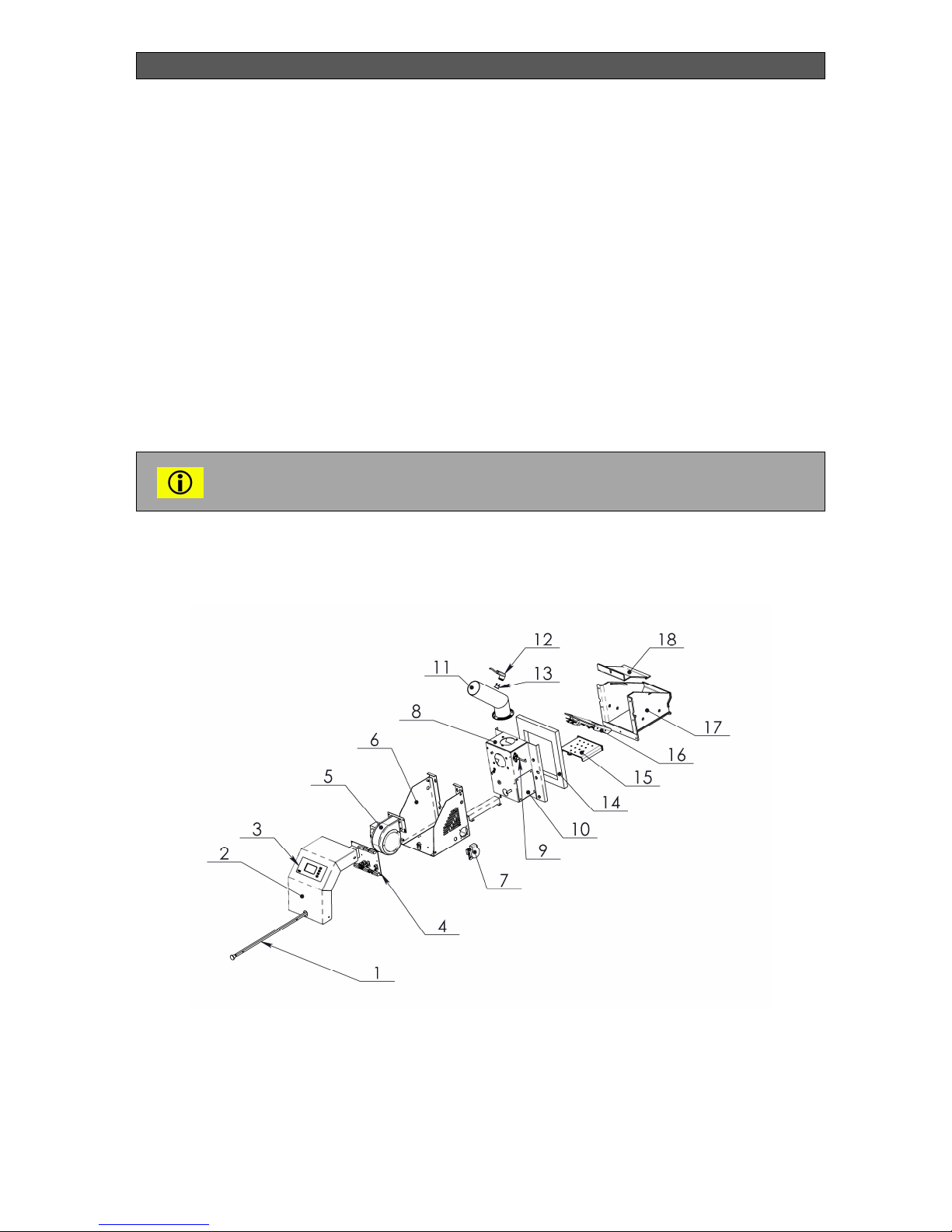
The main components of wood pellet burner series Bisolid GP xx_B hc> are presented in
Figure 1.
Figure 1. Main components of the pellet burner
1. Cleaning device
2. Main module cover panel
3. Front panel – intuitive LCD display
4. Main control board
5. Fresh air fan
6. Main module housing
7. Plug for feeding and control of transport
auger
8. Air box
9. Photosensor
Page 8
INSTALLATION, OPERATION AND MAINTENANCE MANUAL
Bisolid GP xx_B hc> . OM-BSGPHCV02/07/2017/EN 8
10. Cover for main cleaning
11. Pellets feeding pipe
12. Couplung
13. Thermal switch
14. Isolation
15. Fire-grate
16. Igniter
17. Combustion chamber
18. Combustion chamber cover
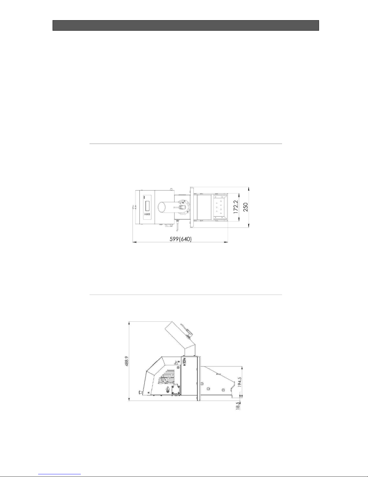
1.5. PELLET BURNER OVERALL DIMENSIONS
The overall dimensions of pellet burner series Bisolid GP xx_B hc> are presented in Figure 2
and Figure 3.
Figure 2. Overall dimensions of the pellet burner
Figure 3. Overall dimensions of the pellet burner
Page 9

INSTALLATION, OPERATION AND MAINTENANCE MANUAL
Bisolid GP xx_B hc> . OM-BSGPHCV02/07/2017/EN 9
The dimension presented in brackets in Figure 3 concerns the length of pellet
burner GP 32_B hc>.
1.6. PELLET BURNER TECHNICAL DATA
Table 2. Technical data for pellet burner series Bisolid GP xx_B hc>
DESCRIPTION DIMENSION
VALUE
GP 20_B18 hc> GP 25_B hc> GP 32_B hc>
Fuel - Wood pellets
Wood pellets category according to
standard EN ISO 17225-2:2014
- A1
Nominal heating output kW 18 25 32
Heating output range (performed by
authorized servicing technician)
kW 5-18 7-25 10-32
Pellet burner size: wide х height x
lenght (W x H х L)
mm
250х488х599 250х488х599 250х488х640
Pellets transport auger size: wide х
length x height (W x L х H)
mm 184 x 1520 x 107
Voltage VАС, Hz 230, 50
Electrical consumption (with ignition) W 100 (+1200 at ignition)
Degree of electrical protection - IP 20
Burner net weight kg 16.9 16.9 17.1
Transport auger net weight kg 8.5 8.5 8.5
Page 10

INSTALLATION, OPERATION AND MAINTENANCE MANUAL
Bisolid GP xx_B hc> . OM-BSGPHCV02/07/2017/EN 10
2. INTRODUCTION
2.1. PELLET BURNER GENERAL REQUIREMENTS
The pellet burner series Bisolid GP xx_B hc> and its accompanying equipment must be
installed and used in accordance to the designed heating installation, all applicable legal
norms, technical standards and manufacturer instructions. The pellet burner should be used
only for the subscribed purposes.
The pellet burner must be installed only for the purposes for which is designed. If the pellet
burner is delivered and installed to the customer by the same person, then the whole
accompanying documentation must be provided as well (especially the user manual book).
The pellet burner’s genuine package should be kept until its initial operation start up, in case it
should be transported again.
After installation the pellet burner operation must be initiated by service organization,
authorized by the manufacturer.
The pellet burner corresponds to the applicable EU legal provisions. If the pellet burner should
be used in countries outside the EU, all deviations from local laws and legal provisions must
be identified and corrected.
In case of faults in the pellet burner please contact a servicing organization, authorized by the
manufacturer. Every incompetent intervention might damage the pellet burner (and possibly
the accompanying equipment).
The servicing technician initializing the pellet burner start up for first time must show the
customer all of its main components and modules, and also how to operate it. The technician
must present the pellet burner’s safety elements and signalization, and respectively the
relevant user reaction. If the pellet burner is delivered and installed to the customer by the
same person, then he must ensure that its genuine package is kept, in case the burner should
be transported again.
Please check the delivery of the pellet burner standard accompanying equipment.
Please check if the delivered model and type of the pellet burner corresponds to the usage
requirements.
If you are not sure how to manage the pellet burner, please carefully read the relevant
instructions in this manual for operation and installation, and respectively continue as
prescribed.
Please never take/stick off or damage the marks and signs on the pellet burner and the fuel
transport auger. Please keep the burner genuine package until its initialization to operation, in
case it should be transported again.
If doing a repair, you must always use genuine spare parts only!
It is forbidden to make any changes to the internal installation of the pellet burner and fuel
transport auger or to change anything in any way.
Page 11

INSTALLATION, OPERATION AND MAINTENANCE MANUAL
Bisolid GP xx_B hc> . OM-BSGPHCV02/07/2017/EN 11
At the end of the pellet burner’s life cycle, it should be packed together with its parts and
disposed in an environmentally safe way.
The manufacture company is not responsible for damage or harms caused by non-compliance
with:
Terms and conditions stated in this manual for operation and installation.
Applicable standards and legal provisions.
Procedures for installation and operation.
Terms and conditions presented in the product warranty card.
Switch off the pellet burner every time when there is any (even momentary)
danger by the presence of flammable or explosive vapors situated in the same
room from which the burner intakes air for burning (for example painting paint
spraying or laying moltening substances, gas leakage, etc.).
2.2. ENSURING PEOPLE AND EQUIPMENT SAFETY
The wood pellet burner and all of its parts are in compliance with the safety requirements of
the relevant EU legal regulations.
In order to install and operate the pellet burner in real-time conditions and in compliance with
its usage designation (stated below only as usage), is necessary also to observe the additional
requirements, as most important of them (those that should not be missed) are presented in
the relevant regulation documents. In addition to the above mentioned documents for the
usage of the pellet burner it is also necessary to comply with this operation and installation
manual and the product accompanying documentation supplied by the manufacture company.
Any intervention over the pellet burner’s operation from children and persons under the
influence of narcotic substances, psychiatric abnormalities and etc., must be prevented.
3. OPERATION INSTRUCTIONS
3.1. OPERATION OF PELLET BURNER SERIES BISOLID GP XX_B
HC>
The pellet burner series Bisolid GP xx_B hc> must be handled only by adult people, which
have been already introduced to the burner operation and its proper handling. The people
operating the pellet burner must strictly comply with the installation and operation manual and
they have rights only to:
Clean the burner.
Fill up the transport auger with fuel.
Clean the photo-sensor periodically.
Adjust the water temperature (operation without optimization with room thermostat).
Change the optimization time (operation with room thermostat).
Check photo-sensor lightness. Do not change its settings.
Check for presence of alarm messages.
Check and adjust temperature for start of water circulations pump.
Page 12

INSTALLATION, OPERATION AND MAINTENANCE MANUAL
Bisolid GP xx_B hc> . OM-BSGPHCV02/07/2017/EN 12
Switch on or off the pellet burner. It is recommended to do it by the key Start, located
on the boiler’s control panel.
Check the pellet burner condition.
After initializing the pellet burner into operation the servicing technician is obligated to
introduce the user with the operation and maintenance of the appliance. Attendance of
children without supervision near the pellet burner is not allowed. Any interventions or
activities over the burner construction that may endanger the life or health of the handling or
attending personal are strictly forbidden.
Usage of flammable liquids for easier firing as well as any activities related to increase of the
pellet burner’s nominal heating output (overloading) are strictly forbidden. Positioning of
flammable objects near the burner is also not allowed.
In case of danger from penetration of flammable vapors or gasses in the boiler
room or any activities that may lead to fire or explosion (gluing the flooring,
varnishing with flammable paints or others), the pellet burner must be led out of
operation before starting any of these activities.
3.2. SAFE OPERATION OF THE PELLET BURNER
All safety prescriptions must be observed when the pellet burner series Bisolid GP xx_B hc> is
operating. The pellet burner must not be used for any other purposes except the ones
introduced in this operation manual.
The surface of the pellet burner should be cleaned only with standard inflammable cleaners.
Positioning of objects made of flammable materials over or near the pellet burner, at shorter
than the safe distance is not allowed.
It is not allowed to store flammable materials (wood, paper, oil and other flammables) in the
same room, where the pellet burner and the boiler are situated.
The recommended safe distance between the boiler, with installed pellet burner series Bisolid
GP xx_B hc>, and the fuel must be minimum 1000 mm.
The minimum allowed distance between the pellet burner’s outer parts and easy or medium
flammable materials, also including fuel, must be at least 400 mm.
Removal of the ash remainings from the burner should be performed by taking out the
combustion chamber fire-grate. The fire-grate, where the ash deposits gather, must be
emptied on time, before its complete filling. All activities related to removal of the ash from the
pellet burner should be performed after cooling of the fire-grate, as the usage of metal pliers is
strongly suggested. Please also use protection gloves as a safety measure.
When installing the pellet burner and the elements for safety and control please
do not forget that all installation works must comply with the safety labor
principles. If a pellet burner or fuel transport auger component replacement is
necessary, please use the recommended elements. In case of using any other
type of component you should ask the manufacturer company first. The pellet
burner and fuel transport auger functionallity must be checked by authorized
servicing specialist once per year.
Page 13

INSTALLATION, OPERATION AND MAINTENANCE MANUAL
Bisolid GP xx_B hc> . OM-BSGPHCV02/07/2017/EN 13
4. PELLET BURNER INITIALIZATION FOR OPERATION
4.1. PELLET BURNER CHECK-UPS BEFORE INITIALIZATION FOR
OPERATION
Before initializing the pellet burner for operation the servicing technician must check:
If the pellet burner series Bisolid GP xx_B hc> is going to be installed on a solid fuel
Bisolid hot water boiler.
If the installation, including the hot water boiler, complies with the project.
If the wood pellets correspond to standard EN ISO 17225-2:2014, class A1.
Electrical supply functionality and working order.
The service technician must train the consumer how to operate and manage
the pellet burner and also to fill in the exact start of operation date in the
warranty card of the product.
4.2. JOINT OPERATION OF PELLET BURNER AND SOLID FUEL
BOILER
The pellet burner series Bisolid GP xx_B hc> is allowed for installation only to hot water
boilers approved by its manufacturer.
The possibility for parallel operation of solid fuel hot water boiler with automated pellet burner
from series Bisolid GP xx_B hc> is based on the fact that the burner manufacturer has
performed multifunctional and precise tests and measurements over the pellet burner
operation with certain type of hot water boilers. Assembly of the pellet burner to a hot water
boiler must be performed with the appropriate installation kit.
The pellet burner’s series Bisolid xx_B hc> can be mounted to the hot water
solid fuel boilers with sufficiently high efficiency.
Page 14

INSTALLATION, OPERATION AND MAINTENANCE MANUAL
Bisolid GP xx_B hc> . OM-BSGPHCV02/07/2017/EN 14
5. OPERATION AND CONTROL OF PELLET BURNER FROM BISOLID
GP XX_B HC> SERIES
5.1. DESIGNATION OF THE PELLET BURNER CONTROLLER
The controller is designated to provide automatic control of the combustion process and
adjustment of the pellet burner’s heating output, depending on the building and premises
heating needs.
5.2. OPERATION OF THE PELLET BURNER CONTROLLER
The device can control the following system modules:
Fuel transport auger.
Fresh air and extraction fans.
Electrical heating element for ignition of the pellets.
Cleaner element for ash cleaning.
Circulations pump for the boiler.
At primary switch on, as well as when switching the power supply off, the burner
goes through stop procedure.
5.3. STARTING THE PELLET BURNER
When missing stop signal or in case of emergency situation and there is difference between
the adjusted and the measured temperature from the To sensor, then the burner starting
procedure initiates. The initial fuel doze is loaded and the ignition switches on. After
establishing the presence of flame the burner heating output increases. When the modulation
zone „Zone_reg” has been reached the burner heating output decreases (there is service
parameter for adjustment) and when the desired temperature has been reached the burner
operates at its minimum heating ouput. When higher than the adjusted temperature has been
reached, the system responds with stop procedure.
When the burner is in the modulation mode and therefore the power is reduced with a
decrease in temperature in the automatic way the power is increased.
Т
,
Т_set
T
P,%
P
zone_reg
Т_set - zone_reg
P
Page 15

INSTALLATION, OPERATION AND MAINTENANCE MANUAL
Bisolid GP xx_B hc> . OM-BSGPHCV02/07/2017/EN 15
5.4. SWITCHING OFF THE PELLET BURNER
In presence of stop signal, emergency situation or measured temperature above the adjusted,
system stop procedure initiates. It is next followed by ventilation time, during which the
combustion chamber cools down and the remaining ash over the fire-grate is being blowed
out.
5.5. BURNER CONTROLL THROUGH GSM MODULE (OPTION)
The control of the burner trough GSM module is done by sending SMS commands. There is
an opportunity to stop, start and review the current status. (See section "SMS commands").
5.6. METHODS FOR FORMING THE DESIRED TEMPERATURE
5.6.1. MANUAL DETERMINATION OF THE HEATING WATER
ASSIGNMENT (Тb set)
In this case, the assignment is independent of other factors such as inside temperature and
the room temperature and the value is selected to maintain. (See section "Service Settings").
5.6.2. DETERMINATION OF THE HEATING WATER ASSIGNMENT ON
OUTSIDE TEMPERATURE THROUGH SENSOR Pt1000
Choice of temperature region.
With the choice of region is determined the curve in which will change the assignment for
heating water depending on the change in outside temperature. All curves have a common
point at an outside temperature of + 20 ° C, which corresponds to the minimum assignment for
the heating water.
W_max
W_min
To, °C
20
10 0
-10
-20
Page 16
INSTALLATION, OPERATION AND MAINTENANCE MANUAL
Bisolid GP xx_B hc> . OM-BSGPHCV02/07/2017/EN 16
5.6.3. DETERMINATION OF THE HEATING WATER ASSIGNMENT ON
ROOM TEMPERATURE THROUGH SENSOR Pt1000 IN THE ROOM
In this case is adjasted the desired temperature in the room and according to its value is
determined the heating water tempearture.
5.6.4. DETERMINATION OF THE ASSIGNMENT FROM ROOM
THERMO REGULATOR
This method is applicable only if is operating with contact room thermostats with
"independent output" (See section "Service Settings").
Time for optimisation.
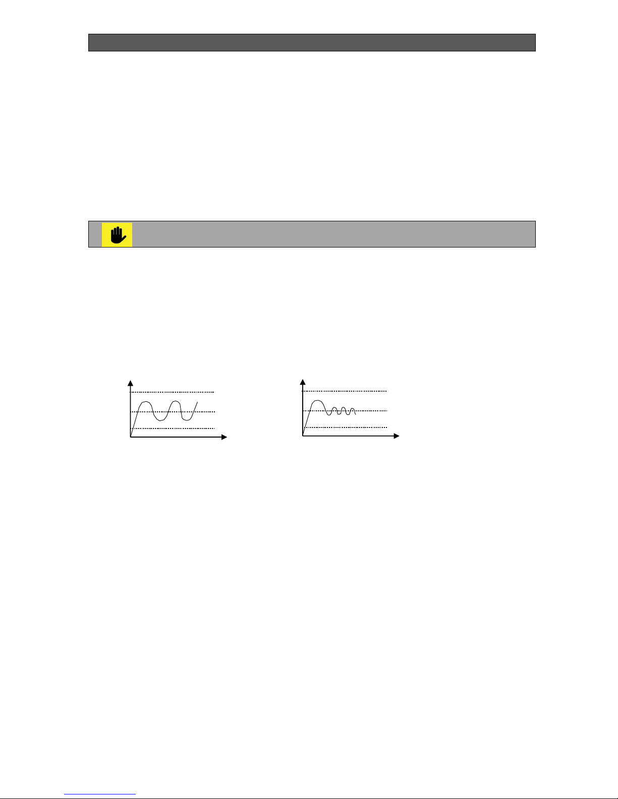
Using of time for optimisation allows to reducing fluctuations in the assignment of the hot
water, which leads to a better control of the hot water. It can choose from 0 to 60 min, in
increments of 5 minutes. (See section "User settings").
When there are switches on and off from the room regulator and it operates without
optimization (0), the heating water adjustment becomes:
At start - maximum.
At stop – minimum.
When there are switches on and off from the room regulator and it operates with optimisation
(5-60 min.), the heating water adjustment becomes:
At start – increase starts, as the maximum assigned temperature value is reached at
the end of the optimization time, only in case there is no stop occured during this
period.
At stop – decrease starts, as the minimum assigned temperature value is reached at
the end of the optimization time, only in case there is no start occurred during this
period.
Т
,
Wmax
ON
OFF
Wmin
W
Without optimisation
Т
,
Wmax
ON
OFF
Wmin
W
With optimisation
Page 17
INSTALLATION, OPERATION AND MAINTENANCE MANUAL
Bisolid GP xx_B hc> . OM-BSGPHCV02/07/2017/EN 17
5.7. TEMPERATURE AND SECURITY RESTRICTIONS
When managing the pellet burner series Bisolid GP xx_B hc> it is necessary to consider the
following temperature and security limitations:
Minimum assignemt for inlet water temperature.
Maximum assignemt for inlet water temperature.
Water freezing protection.
Boiler overheating and „back-fire” protection.
Circulations pump blocking protection.
Water freezing protection – starts the burner when the temperature is below 5
°С. Boiler overheating and „back-fire” protection – input signal from the blocking
thermostat, and when the signal contact is opened the burner stops.
Circulations pump blocking protection – drives/rotates the pump for 5 minutes,
in case it has not been operating for at least 24 hours.
The minimum and the maximum assignment of the heating water temperature determinate the
limits of the supplied water to the premises. (See "Service Settings").
5.8. FRONT CONTROL PANEL OF THE PELLET BURNER
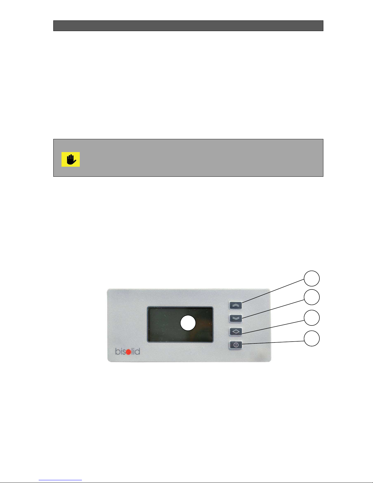
The front control panel is presented in Figure 4 – intuitive LCD display of pellet burner series
Bisolid GP xx_B hc>.
Figure 4. Front control panel of pellet burner series Bisolid GP xx_B hc>
1. Front panel indication – intuitive LCD display.
2. Changing button “next” / or manually switching on/off the pellets transport auger (if
holded for 5 sec. together with additionally known conditions described below).
3. Changing button “back”.
4. Button for enter / exit from programming mode (user settings), switch ON / OFF (if
holded for 5 sec).
5. Button ON / OFF.
3
4
5
1
2
Page 18

INSTALLATION, OPERATION AND MAINTENANCE MANUAL
Bisolid GP xx_B hc> . OM-BSGPHCV02/07/2017/EN 18
In the basic state the display shows the following parameters:
1. Time and day of the week.
2. Execution of weekly program N ....
3. Stop / Start / Burn - performed procedure.
4. Current exploited power.
5. Indicator cleaner work / entry into cleaning.
6. Indicator ignitor operation or alarm.
7. Indicator work auger blinks in manual switching.
8. Indicator working fans.
9. Indicator working pump.
10. Tr - room temperature (assignment) / To-inside temperature (curve) / Rth-room thermostat
/ when not press a button, information about the current operation.
11. Tfg - temperature flue gas (assignment).
12. Fire - light sensor (assignment).
13. Tb - water temperature.
5.9. OPERATION (FUNCTIONING) OF THE PELLET BURNER
In this part of the operation manual is presented information only for the users.
The information for servicing specialists is presented separately.
The controller of the pellet burner is swithcing on and off by pressing and holding the button
ON / OFF. When the burner is swithc off then appears "Stopped".
In the off position when on the display shows one of the above messages by pressing and
holding for about 10 seconds on the button „” can be switched on and off in manual way
pellet auger with aim filling when the auger is empty.
Before manually switching on of pellet burner you have to verify that the burner
is burnt out.
With buttons „” or „” scroll until on the display is shown the menu with the desired
parameters, then press „”:
For choice of settings, scroll move the cursur „*” with buttons „” or „” to make
change and return to choice of settings press button „”.
The setting which changes startsto blink, with buttons „” or „” you can change the
net value.
After completing the settings, select „EXIT” and press button „” to save the
changes.
Page 19

INSTALLATION, OPERATION AND MAINTENANCE MANUAL
Bisolid GP xx_B hc> . OM-BSGPHCV02/07/2017/EN 19
The controller (the pellet burner) can be switched on or off by the front panel or
by the remote control electrical input. The remote control input is usually
connected to a START key with two resistant positions. WE RECOMMEND
THAT THE BURNER IS SWITCHED ON OR OFF BY THIS START KEY!
The controller switches off no matter which source sends STOP command, but
can be switched on only when there is START command on both places.
5.9.1. USER’S SETTINGS
Table 3. Parameters of pellet burner user’s settings
5.9.2. WEEKLY TIMER
NAME DESIGNATION
LIMMITS FACTORY
SETTING
Assignment for:
Water temperature (manual)
Room temperature
Room thermostat -optimisation
Temperature region
(depends on „Type control”)
Tb set
Troom set
Rth delay
region
Tmin – Tmax °C
5 – 35 °C
0 – 60 min
-20 ÷ 20 °C
80 °C
22 °C
0
-10 ÷ 20 °C
Assignment sensor light Fire set 0 – 99 % 50 %
Assignment flue gases
temperature
Tfg set 0 – 250 °C 40 °C
Assignment switch on pump Tpump set 10 – 70 °C 40 °C
Current time and day time&d hh/mm/d
Language Language Eng / Bul Eng
User’s Settings
*Troom set 22°C
Fire set 50%
Tfg set 80°C
Tpump set 40°C
User’s Settings
time&d 08:30 Fr
Language Eng
EXIT
Weekly timer
*Program 1
00:00 to 24:00
SuMoTuWeThFrSa
EXIT
Page 20
INSTALLATION, OPERATION AND MAINTENANCE MANUAL
Bisolid GP xx_B hc> . OM-BSGPHCV02/07/2017/EN 20
Table 4. Parameters of weekly timer settings
To operate the controller must be set interval to work at least one of the four
programs. When set to the same start and end time of the interval program is
inactive.
Switchng off on weekly timer is indicated by Pr.0, at work displays the number of the relevant
active program (Pr.1 - Pr.4).
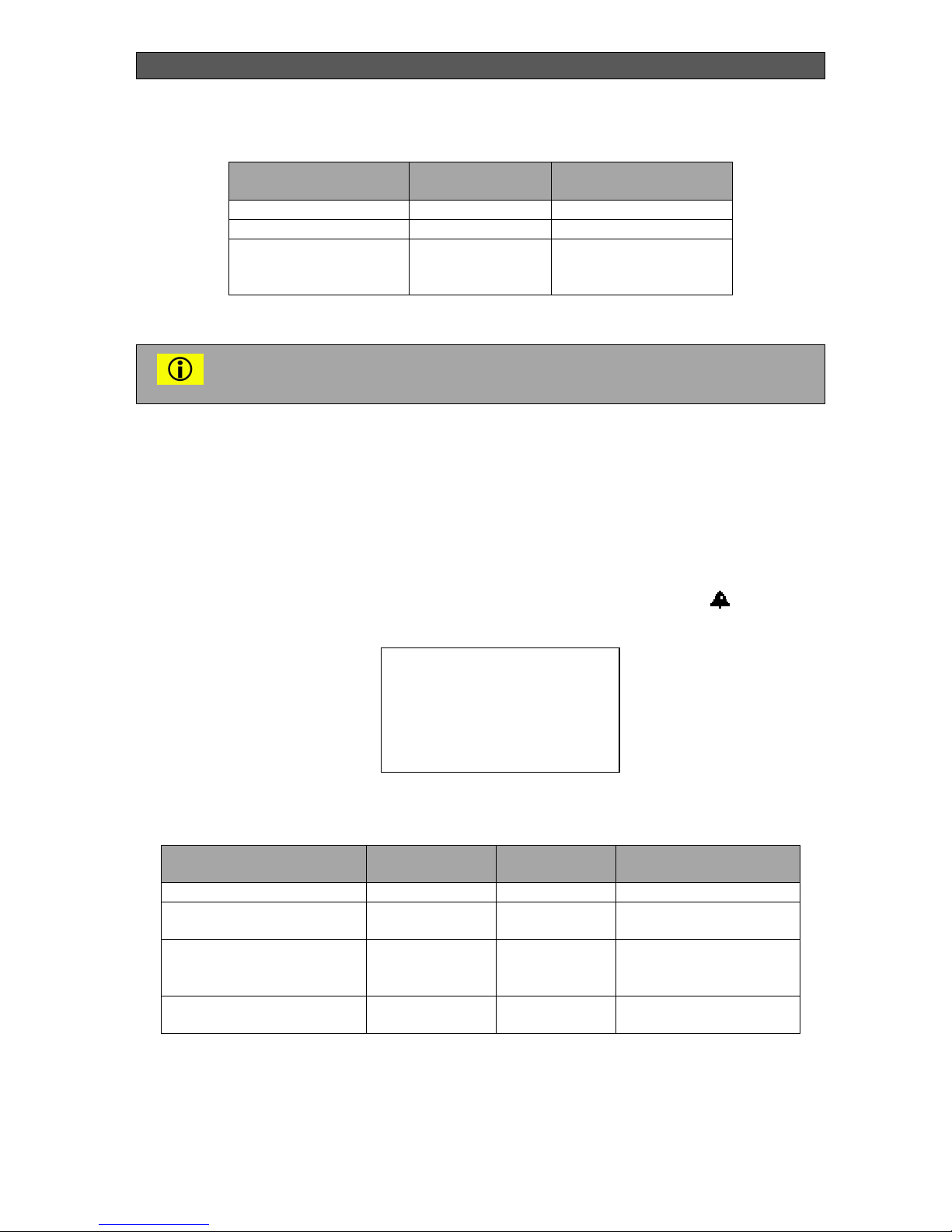
5.9.3. INFORMATION ON ALARM MESSAGES
The presence of an alarm message on the pellet burner is indicated by an icon .
Table 5. Information on alarm messages
ОК – normal condition, Err – alarm message.
NAME DESIGNATION
LIMMITS
Program number Program 1 - 4
Interval 00:00 – 24:00
Day of the week SuMoTuWeThFr
Sa
Su – Sa
(from Sunday to
Saturday)
NAME DESIGNATION CONDITION RECOVERY
No flame No Fire OK / Err Switch off and on
Danger of frost Low Tb OK / Err Increasing of
temperature
Overheat
(activated blocking
thermostat)
In BT OK / Err Switch off and on
No airflow
(device for flow)
Air flow OK / Err Switch off and on
Alarm
No Fire OK
Low Tb OK
In BT OK
Air flow OK
Page 21

INSTALLATION, OPERATION AND MAINTENANCE MANUAL
Bisolid GP xx_B hc> . OM-BSGPHCV02/07/2017/EN 21
5.10. SERVICE SETTINGS
When using the service controller settings of the pellet burner, access is performed by a
password. The password is activated again after exiting of the menu, if within 15 sec. button is
not pressed.
The procedures for service settings of the pellet burner are protected by
password and can be used only for trained service specialists that have
additional information.
5.10.1 COMMON SETTINGS
Table 6. Parameters of pellet burner common settings
NAME DESIGNATION
LIMMITS FACTORY
SETTING
Water limmits Tb lim 5 – 90 °C 15 – 80 °C
Zone regulation Zone reg 5 – 30 °C 10 °C
Type of control mode
Type control
0 – manual
1 – room thermostat
2 – room temperature
3 – outside
temperature
1
Choise of flame sensor Flame sensor 0 – photo
1 – flue gases
0
Recovery from the loss of
power
Lose AC Restore 0 – “Stop”
1 – “Burn”
0
Delayed of the reaction of
the flow sensor
FC delay
1 – 240 s
30
Hysteresis room
temperature
Troom his 1 – 3 °C
(type control 2)
3
Common Settings
*Tb lim 15 – 80 °C
Zone reg 10 °C
Type control 1
Flame sensor 0
Common Settings
*Lose AC Restore 0
FC_delay 5
Troom his 3°C
EXIT
Page 22

INSTALLATION, OPERATION AND MAINTENANCE MANUAL
Bisolid GP xx_B hc> . OM-BSGPHCV02/07/2017/EN 22
5.10.2 IGNITION SETTINGS
Table 7. Parameters in pellet burner ignition settings
5.10.3 SETTINGS IN BURN MODE
Table 8. Parameters of pellet burner settings in burn mode
NAME DESIGNATION
LIMMITS FACTORY
SETTING
Time for loading Load 2 – 480 s 90 s
Blowing Blowing 0 – 10 m 2 m
Time for the emergence of
flame
Fire time 1 – 15 m 8 m
Preheating Preheat 0 – 180 s 100 s
Fresh air fan Fan1 20 – 100 % 48 %
Flue gases fan Fan2 20 – 100 % 100 %
Time for fuel heated Inflame 60 – 600 s 120 s
NAME DESIGNATION
LIMMITS FACTORY
SETTING
Time for loading Load 1 – 240 s 2 – 8 s
Time for burning Pause 1 – 240 s 14 – 14 s
Fresh air fan Fan1 20 – 100 % 48 – 100 %
Flue gases fan Fan2 20 – 100 % 48 – 100 %
Ignition
*Load 90 s
Blowing 2m
Fire time 8 m
Preheat 100 s
Ignition
*Fan1 48 %
Fan 2 100 %
Inflame 120 s
EXIT
Min<Burn>Max
*Load 2 - 8s
Pause 14 - 14s
Fan1 48 - 100%
Fan2 48 - 100%
EXIT
Page 23

INSTALLATION, OPERATION AND MAINTENANCE MANUAL
Bisolid GP xx_B hc> . OM-BSGPHCV02/07/2017/EN 23
5.10.4 SETTINGS IN STOP MODE
Table 9. Parameters of pellet burner settings in stop mode
5.11. SMS COMMANDS
GSM module is offered as an option, it connects to "CON7" the board with indication. When
the module is available, display shows the symbol for GSM. SMS commands must be in Latin
characters, as assuming only large or only small letters.
Example: BSTOP and bstop – correct, Bstop – wrong.
Table 10. Description of GSM commands for pellet burner control
BSTOP and BSTART commands have the same effect as a button ON / OFF, as in switch on
condition is executed the set weekly program.
NAME DESIGNATION
LIMMITS FACTORY
SETTING
Time for afterburning Burn out 0 – 15 m 8 m
Time for cleaninhg Clean on 0 – 24 h 6 h
Moving of cleaner Cleaner move 1 – 99 s 3 s
Number of cleaner cycles Cleaner cycle 1 – 3 1
NAME DESIGNATION
ACTION
Stop pellet burner BSTOP Burner stops – the same like with button ON / OFF
Start pellet burner BSTART Burner starts – the same like with button ON / OFF
Current condition BINFO Send SMS with the current condition
Telephone in an
emergency
BPHONE Recorded phone from which the message is sent if
there is no flame, no air flow or the blocking
thermostat is activated and sends alert
Stop settings
EXIT
Stop settings
*Burn out 5 m
Clean on 6 h
Cleaner move 3 s
Cleaner cycle 1
Page 24

INSTALLATION, OPERATION AND MAINTENANCE MANUAL
Bisolid GP xx_B hc> . OM-BSGPHCV02/07/2017/EN 24
In an emergency, if no recorded number is checked for the last sent SMS and if it is missing
and he is not sent alert.
During the receiving of SMS command is returning SMS response to the number from which
the command is recieved.
5.12. CONNECTING THE PELLET BURNER TO THE ELECTRICAL
POWER SUPPLY
When connecting the pellet burner series Bisolid GP xx_B hc> to the electrical power supply
installation it is necessary to have in mind the following technical characteristics (Table 11).
Table 11. Pellet burner technical characteristics
DESCRIPTION
CHARACTERISTIC
Supply voltage ~230V; 50Hz
Ignition element output ~230V; 0.3kW
Circulations pump output ~230V; 0.35kW
Fans ouput (3 pices) ~230V; 0.25kW
Fuel transport auger output ~230V; 0.25kW
Cleaner supply voltage 24V DC
Reversible cleaner output 24V/4А
Heating water sensor Pt 1000 (-50 to +250 °С)
Flue gases sensor Pt 1000 (-50 to +250 °С)
Flame detecting sensor Phototransistor
Room thermostat input Independent contact
Flow sensor input Independent contact
Measuring range 50 +350 °С
Measurment dimension 1 °С
Humidity Up to 80.0%
Degree of protection IP20
All works and activities with regards to connecting the pellet burner to the
power supply system must be performed by certified trained person.
The pellet burner must be connected to the electrical installation of the
appliance to which it is attached, by observing the safety technique rules.
Page 25

INSTALLATION, OPERATION AND MAINTENANCE MANUAL
Bisolid GP xx_B hc> . OM-BSGPHCV02/07/2017/EN 25
5.13. WARRANTY AND WARRANTY CONDITIONS
We pay attention to customers that initializing into operation and technical servicing of all
pellet burner series Bisolid GP xx_B hc> must be performed by specialized installation
company. Otherwise any eventual warranty claims will not be accepted. Warranty issues must
be claimed just after the defect has been discovered. The manufacturer reserves the right to
make changes, related to the product technical optimization. The warranty period is presented
in the pellet burner’s warranty card, which is its main belonging and is determined by the
precise observation of the instructions in the current manual for installation, operation and
maintenance. The Buyer has to issue a warranty claim in written form and present it to the
Seller or to an authorized servicing company.
5.14. PELLET BURNER PACKAGE KIT AT DELIVERY
All wood pellet burner series Bisolid GP xx_B hc> are delivered fully assembled and
functionally tested.
The main pellet burner accessories are:
Installation and operation manual 1 pc.
Warranty card 1 pc.
Main module with combustion chamber 1 pc.
Isolation 1 pc.
Fuel transport auger 1 pc.
Spare parts and accessories for the pellet burners can be ordered to the servicing technician
who performed the installation or directly to the supplier.
5.15. PELLET BURNER CLEANING
When the pellet burner operates continuesly ash and/or slag gather over the surfaces of the
fire-grate, located in the burner’s combustion chamber, and decrease the appliance efficiency.
The accumulated ash or/and slag quantity depend mainly on the operation modes of the
appliance and the type of used fuel.
Cleaning of the pellet burner series Bisolid GP xx_B hc> has to be performed according to the
necessity and operation conditions, but at least from once per week to one per day.
The number and frequency of cleaning of the burner depend largely on the
quality of the wood pellets. Fuel is necessary to meet the standard
EN ISO 17225-2:2014, class A1.
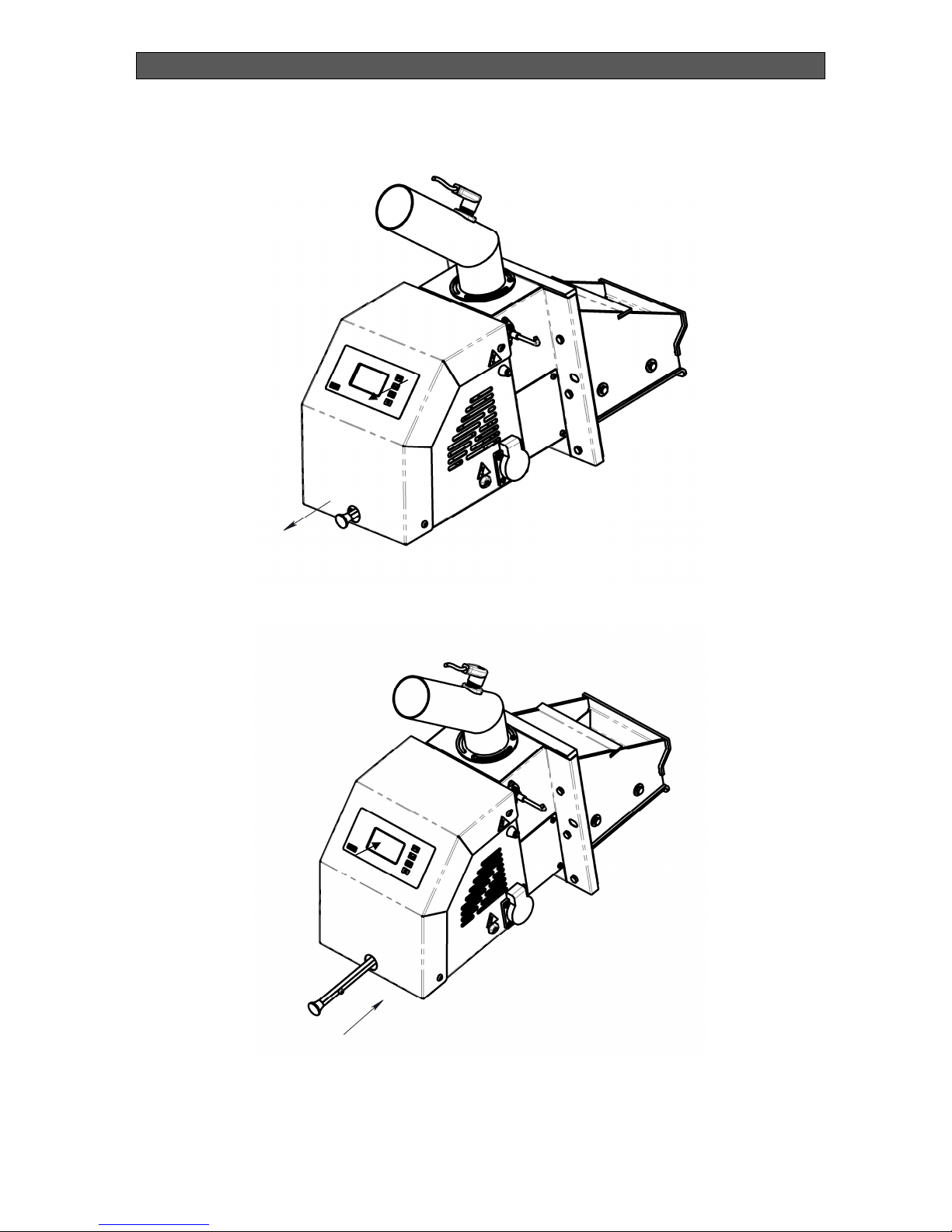
Figure 5 and Figure 6 present description of the sequence of actions in mannually mechanical
cleaning of the burner series Bisolid GP xx_B hc>.
Page 26
INSTALLATION, OPERATION AND MAINTENANCE MANUAL
Bisolid GP xx_B hc> . OM-BSGPHCV02/07/2017/EN 26
Figure 5. Dscription of actions in manually cleaning of the burner
Figure 6. Dscription of actions in manually cleaning of the burner
Page 27

INSTALLATION, OPERATION AND MAINTENANCE MANUAL
Bisolid GP xx_B hc> . OM-BSGPHCV02/07/2017/EN 27
1. The handle of the cleaning mechanism of the burner is pulled back until it stops moving
as shown in Figure 5.
2. The handle is moved forward until it stops moving as shown in Figure 6.
3. This action is repeated 2 to 3 times for the complete cleaning of the fire-grate, once per
a day.
The handle of the cleaner should be in extremely retracted position to the
burner to allow the pellet burner to operate normally.
The pellet burner series Bisolid GP xx_B hc> is cleaned in the following cases:
During the operation of the pellet burner:
- The pellet burner can be cleaned and at its operation. In this way of cleaning is
discarded small dose unburned fuel, but the advantage is that there is no need any
waiting time, i.e., cleaning can be done immediately on the customer request. The
burner is programmed to continue working after this type of cleaning.
Cleaning of the pellet burner without interrupting the operation of the device:
- When a device does not operate assigned to it by the program, for example daily or
weekly thermostat.
- When a device does not operate and is in standby mode due to the achieved
temperature.
When the pellet burner is switch off:
- When a device is switched off by the user, it is necessary waiting for the complete
combustion of residual fuel according to the parameters listed in Table 9.
The cleaning of the pellet burner, which is carried out from outside with the help
of the mechanism for cleaning, does not require protective equipment.
5.16. PELLET BURNER SERVICING
The regular pellet burner servicing by the user guarantees efficient, economic and reliable
operation of the appliance.
The user has to periodically, at least once per day or longer, depending on the fuel ash
content, but no longer than five days of operation, to switch off the burner. This measure
guarantees effective after-burning of the fuel and combustion chamber cooling.
After the pellet burner cools down the ash and/or slag must be cleaned from the combustion
chamber fire-grate. The flexible pipe connecting the fuel transport auger and the burner fuel
inlet pipe must be cleaned from dust at least once per week.
Dust depositing on the flexible pipe walls can lead to distortion of the fuel
feeding, ignting the dust as a result of emergency situation, in consequence of
which hot flue gasses might pass through it.
Page 28
INSTALLATION, OPERATION AND MAINTENANCE MANUAL
Bisolid GP xx_B hc> . OM-BSGPHCV02/07/2017/EN 28
5.16.1. BASIC AND PERIODIC CLEANING OF PELLET BURNER
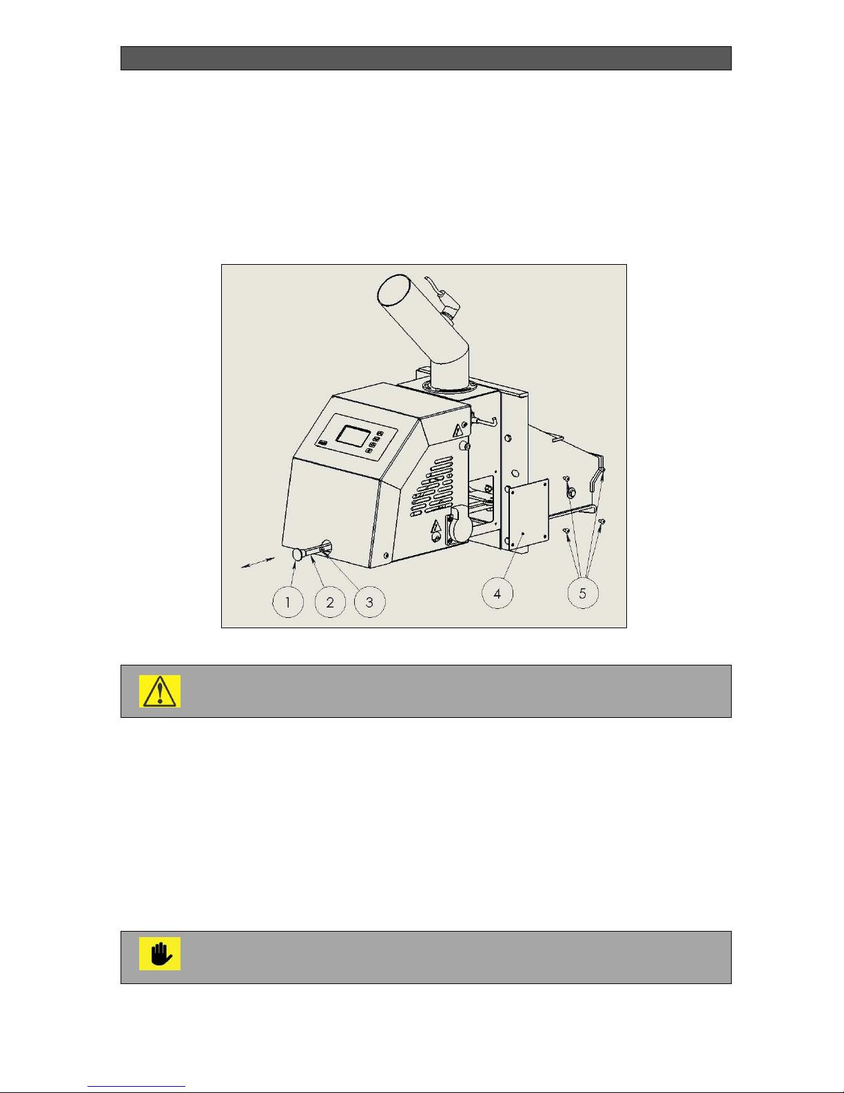
Figure 7 presents the way of basic or periodic cleaning of pellet burner from series Bisolid GP
xx_B hc>.
Figure 7. Basic or periodic cleaning of pellet burner from series Bisolid GP xx B hc>
.
The basic or periodic cleaning of the equipment is carried out in completely
cooled pellet burner.
The sequence of actions in primary and periodic cleaning of the pellet burner series Bisolid GP
xx_B hc> (see Figure 7) is as follows:
1. Pull the handle 1 back. Unscrew and remove the handle 1 and screw 3. Push the rod all the
way forward 2 and remove the fire gtare from the burner. You must have access to the
combustion chamber of the burner.
2. Unscrew the screws 5 (4 pieces) and remove the cover 4.
3. Using vacuum cleaner with placed suitable nozzle, clean the space under and behind the
pellet burner fire grate.
The assembly of components and parts of the burner after cleaning is done on the way back.
It is necessary that the user is fully introduced with the information presented in
the current operation manual, in connection with the pellet burner operation, its
control and servicing.
Page 29

INSTALLATION, OPERATION AND MAINTENANCE MANUAL
Bisolid GP xx_B hc> . OM-BSGPHCV02/07/2017/EN 29
6. INSTALLATION INSTRUCTIONS FOR PELLET BURNER SERIES
BISOLID GP XX_B HC>
6.1. PELLET BURNER INSTALLATION – COMMON INFORMATION
The wood pellet burner series Bisolid GP xx_B hc> must be installed only by specialized
company, authorized for such activities. The pellet burner installation must be performed
depending on the solid fuel hot water boiler type from Bisolid series, the preliminary designed
project and acting legal provisions.
The existing networks of authorized service organizations comply with these conditions and
are able to take responsibility for all pellet burners Bisolid GP xx_B hc> (GP 20_B18 hc>, GP
25_B hc> и GP 32_B hc>) installations, their initialization in operation and warranty repairs.
Installation of the pellet burner must comply with the acting regulations and directives as well
as to the operation and installation manual. The manufacturer is not responsible for failures or
damages caused by unqualified installation.
The pellet burner series Bisolid GP xx_B hc> must be connected to the power
supply only by qualified authorized person.
All problems (failures) caused by incorrect installation of the pellet burner are
not covered by the pellet burner’s warranty cards.
6.2. CHOOSING A PELLET BURNER
The choice of suitable pellet burner series Bisolid GP xx_B hc> is necessary to be made
accordingly to the heating output of the different types and models hot water boilers Bisolid.
The correctly chosen pellet burner used for installation to the mentioned hot water solid fuel
boilers guarantees economic and optimum operation of the system boiler – burner.
The choice of pellet burner with too high nominal heating output, compared to the boiler’s
output, leads to increased consumption and fuel expences.
The choice of pellet burner with much lower nominal heating output, compared to the boiler’s
output, leads to impossibility for reaching the boiler’s nominal parameters and low efficiency
Page 30

INSTALLATION, OPERATION AND MAINTENANCE MANUAL
Bisolid GP xx_B hc> . OM-BSGPHCV02/07/2017/EN 30
6.3. POSITIONING OF THE PELLET BURNER
The pellet burner series Bisolid GP xx_B hc> can be installed on hot water boilers, which are
positioned in uninhabitable premises (for example boiler room, basement).
The pellet burner and boiler room must have constant fresh air intake, needed for the burning
process. The air has to be clean, without halogen hydrocarbons, corrosive vapors and should
not be too wet and dusty. The room must be protected against freezing, with ambient
temperature in the range from +5°C to +35°С and with no more than 80% relative humidity of
the air.
Safe 200 mm distance must be kept in the cases when the flammability level of the material is
unknown. The same safety distance must be kept also for domestic objects, flammable
materials and fuels situated in the room, where the burner is positioned.
Do not put flammable materials over burner’s main module top side or near it
within the safety distance.
The main module of the pellet burner series Bisolid GP xx_B hc> must be installed in
horizontal position towards a suitable solid fuel hot water boiler. The pellet burner position has
to be considered so it can provide its reliable operation, easy cleaning, handling and servicing.
Correct positioning during the pellet burner installation guarantees reliable and efficient
parallel operation of the burner and the hot water boiler.
The fuel transport auger must be installed near to the already installed pellet burner, in order
to secure its good connection, through the flexible pipe, with the burner’s main module fuel
supply pipe.
About the positioning of the fuel transport auger we recommend that the angle between the
horizont plane and the auger center axis is 45o. By this way an optimum operation of the auger
motor and the burning process will be guaranteed.
If the fuel transportation auger’s angle changes, then the wood pellet
consumption changes respectively depending on the pellet burner heating
ouput.
When the fuel transportation auger’s angle decreases, then the wood pellet consumption
increases and respectively the pellet burner heating output increases. When the fuel
transportation auger’s angle increases, then the wood pellet consumption decreases and
respectively the pellet burner heating output decreases.
The fuel transport auger and the wood pellets hopper, where it is located, positions are
recommended to be situated in a way that provides easy access to the pellet burner, for the
purposes of adjustment, cleaning and servicing.
Page 31

INSTALLATION, OPERATION AND MAINTENANCE MANUAL
Bisolid GP xx_B hc> . OM-BSGPHCV02/07/2017/EN 31
6.4. TRANSPORTATION AND STORAGE
The pellet burners for expedition are offered by the manufacturer in carton packages and are
secured against moving. The pellet burners can not be transported in position different from
their base (normal operating position).
During transportation and storage the pellet burners packages and cover panels should not be
pressed.
Page 32
INSTALLATION, OPERATION AND MAINTENANCE MANUAL
Bisolid GP xx_B hc> . OM-BSGPHCV02/07/2017/EN 32
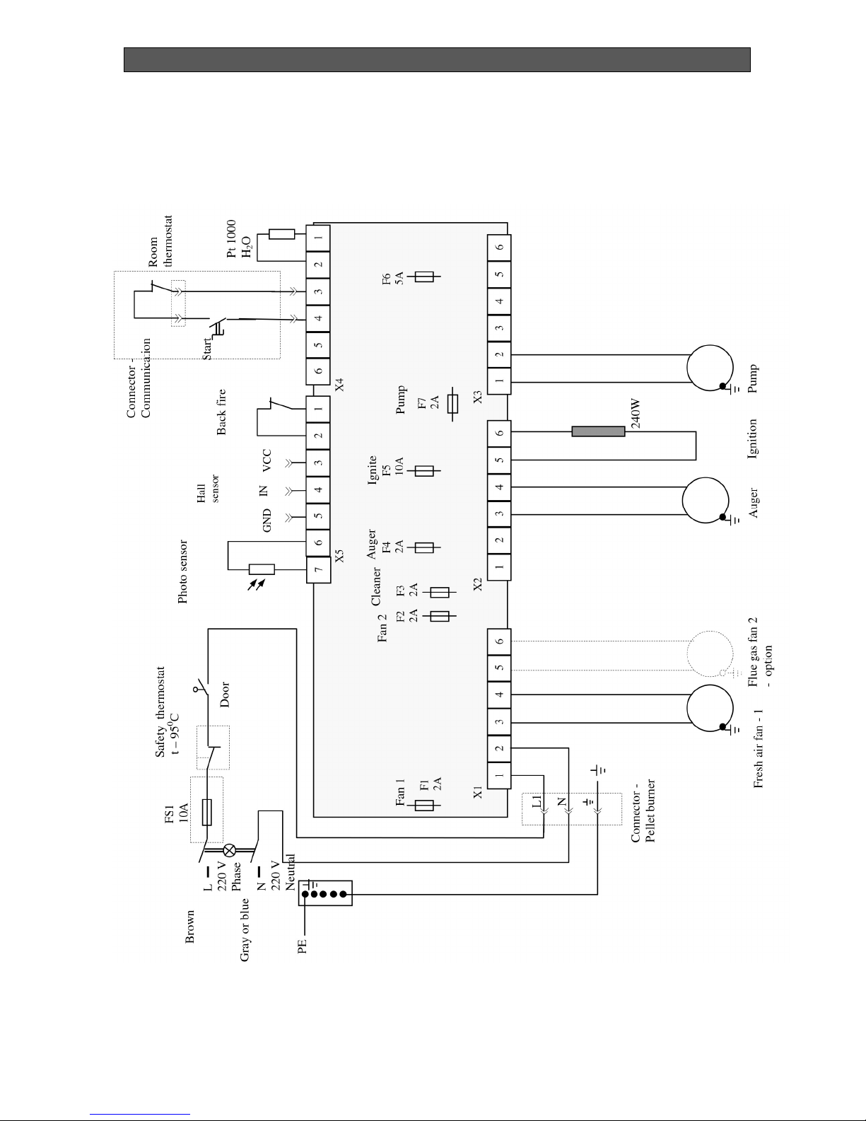
7. PELLET BURNER WIRING DIAGRAM
Figure 7. Wiring diagram of the pellet burner
Page 33

INSTALLATION, OPERATION AND MAINTENANCE MANUAL
Bisolid GP xx_B hc> . OM-BSGPHCV02/07/2017/EN 33
8. TROUBLESHOOTING
The burner is installed
on a heating boiler, but
the temperature in the
rooms is low.
Insufficient heating output. It is necessary to increase the burner’s
heating output level.
Low assigned water temperature. It is necessary to increase the water
temperature assignment. It is also
necessary to chek the circulation water
assignment, adjusted in the burner
controller.
Low assigned temperature by the
room thermostat (if connected).
It is necessary to increase the
temperature assignment by the room
thermostat.
The burner is installed
on a heating boiler and
the temperature in the
rooms is high.
Heating output, exceeding the
heat consumption.
It is necessary to decrease the
burner’s heating output.
High adjusted temperature. It is necessary to decrease the
assigned value (recommended
decrease to minimum 60oC) or the
assigned circulation water
temperature, defined in the controller.
High assigned temperature by the
room thermostat (if connected).
It is necessary to decrease the
temperature assignment by the room
thermostat.
The burner is switched
on, but there is no
burning process.
There is no assignment for
operation.
Check the operation assignment from
the burner control module.
Difficult fuel ignition. The used wood pellets are with
low quality.
It is necessary to change the pellets,
as possibly their water content is
higher than the normal needed for the
burner operation.
The fuel ignition is
accompanied by
untypical noises.
Insufficient chimney draught. It is necessary to check the chimney
and the appliance condition, to which
the burner is installed and to clean the
ash deposits. After cleaning is possible
to adjust the burner operating
parameters – ask for service assist.
Hot water boiler
overheating – to which
the burner is installed.
Lack of heating load or incorrect
heating ouput adjustment of the
boiler and the burner.
It is necessary to check the correct
operation of the system boiler-burner
and eventual adjustment of the
operating parameters – to be
performed by a specialist. After boiler
cooling and failure removal the
emergency thermostat has to be
deactivated (unscrew protection cover,
press the button and screw the cover
againg). Start the burner by restarting
it.
Fuel does not ignite. No wood pellets in the fuel hopper. The fuel hopper, from which the
transport auger takes fuel, must be
refilled.
No fuel in the burner combustion
chamber.
The process of initial firing can be
renewed by restarting the burner.
Presence of fuel over the burner
fire-grate, but is not fired or it is
burned and there is still lack of
burning process.
Clean the gathered fuel over the
burner fire-grate. If the ignition heating
element is out of order or inactive, then
it must be replaced.
Incorect operation of the photosensor used for burning process
The photo-sensor used for burning
process monitoring must be adjusted
Page 34

INSTALLATION, OPERATION AND MAINTENANCE MANUAL
Bisolid GP xx_B hc> . OM-BSGPHCV02/07/2017/EN 34
monitoring. or repaced – to be performed by
servicing specialist only.
The burner does not
start or stops operation.
No power supply. Check if the burner display and its
indication operate. Check working
order of the appliance power supply, to
which the burner is installed and
powers it with voltage 230 VAC, 50 Hz
– to be performed by servicing
technician. Check burner correct
wiring, according to the presented
wiring diagram. Check for loose
electrical connections – to be
performed by servicing technician.
No start signal to the burner. Check if the burner has received start
signal and if the module, providing
signal for operation to the burner,
wiring is in working order – to be
performed by servicing technician.
Check for loose electrical connections.
Check the working order of the burner
operation control module, which
provides voltage and necessary
signals.
The burner does not operate even
if there is operation signal.
Check for activated emergency alarm
– check the list with alarm modes and
indications of the controller, presented
in the next table.
Blown fuses.
To be performed
by
servicing
technician: check the fuses condition
and if there is necessity for
replacement, then change the fuses
with the same corresponding
parameters (Warning: the fuses are
fast-reacting).
The flame from the
burning process is
“dim”and the chimney
smokes much.
Wood pellets with low quality. It is necessary to change the pellets,
as possibly their water content is
higher then the normal needed for the
burner operation.
Unsuitable adjustment of the
burner parameters.
Adjustment of the appliance operating
parameters is necessary – to be
performed by specialist.
The burner starts but it
can not reach to
stabilized condition.
Incorrectly positioned photosensor.
Change the photo-sensor, used for
burning process monitoring, position
by rotating it around its longitudinal
axis.
The photo-sensor surface is dirty. Clean the dirts carefully.
The photo-sensor is damaged –
there are burnout traces on its
surface.
It is necessary to replace the photo-
sensor with new one – ask for service
assistance. Reason – incorrect burner
switch off.
Unstable operation of
the burner.
Photo-sensor failure. Check photo-sensor working order.
Controller operation settings are
changed.
Check the burner heating output level
setting.
Check the controller settings – to be
performed by servicing technician.
Excess heating of the
burner’s pellet inlet pipe.
Insufficient chimney draught or
presence of dirt.
It is necessary to clean the appliance
and the chimney if necessary. Possible
solution is to install flue gas extractor
fan or/and change the chimney.
Page 35

INSTALLATION, OPERATION AND MAINTENANCE MANUAL
Bisolid GP xx_B hc> . OM-BSGPHCV02/07/2017/EN 35
Heating of the burner’s
pellet inlet pipe and
emergency thermostat
activation.
Low chimney draught or the
appliance is contaminated with
dust particles.
It is necessary to clean the appliance
and the chimney, if necessary. It is
necessary to restart the burner.
Possible solution is to install flue gas
extractor fan or/and change the
chimney line.
Dirty and/or melted
photo-sensor.
Incorrect burner switching off. It is necessary to clean the photo-
sensor surface or to replace it with new
one. It is necessary to observe the
burner switch off procedure, presented
in the manual guide.
Presence of unburned
fuel over the combustion
chamber fire-grate.
Inefficient fuel combustion. It is necessary to adjust the appliance
operation parameters – it is necessary
to ask for consultation or adjustment
by authorized technician.
Slag deposits over the
combustion chamber
fire-grate.
The used fuel is with high ash
content and does not comply with
the appliance requirements.
Change the fuel with other one,
complying with the burner
requirements for reliable operation.
Burner operation mode over its
nominal heating output.
Decrease the burner heating output by
changing its heating output level.
Failure, showed on the
controller display
Problem in the burner operation. It is possible to ask for servicing
assistance/consulation.
The burner has stopped,
but after new start it
operates.
The photo-sensor sends wrong
information to the controller.
Check the fuel quantity over the burner
fire-grate. Ask for assistance for
adjustment or consultation by servicing
technician.
High flue gas
temperature (if
thermometer is
installed).
Dirty heat-exchanging surfaces,
depending on the appliance type
and operation mode.
It is necessary to clean the heat-
exchanging surfaces of the appliance.
Smoke presence in the
boiler room after a
period of operation.
Dirty or clogged with ash flue-gas
line inside the appliance – which
consumes the heat energy.
Clean the appliance from the ash
deposits – which consumes the heat
energy.
Failure of the device for
cleaning the burner
The cleaning can not be
performed correctly
What is needed is a competent
consultation and / or intervention
service technician
Other, not described
above failures.
It is necessary to ask servicing
technician for consultation or/and for
his intervention.
In all other cases, the removal of eventual failures and damages must be performed by the
manufacturer or by authorized servicing company.
Page 36

INSTALLATION, OPERATION AND MAINTENANCE MANUAL
Bisolid GP xx_B hc> . OM-BSGPHCV02/07/2017/EN 36
Supplier:
Address:
City:
Street:
Tel.:
Fax.:
http://
Reserved rights for technical changes!
 Loading...