

Page 1
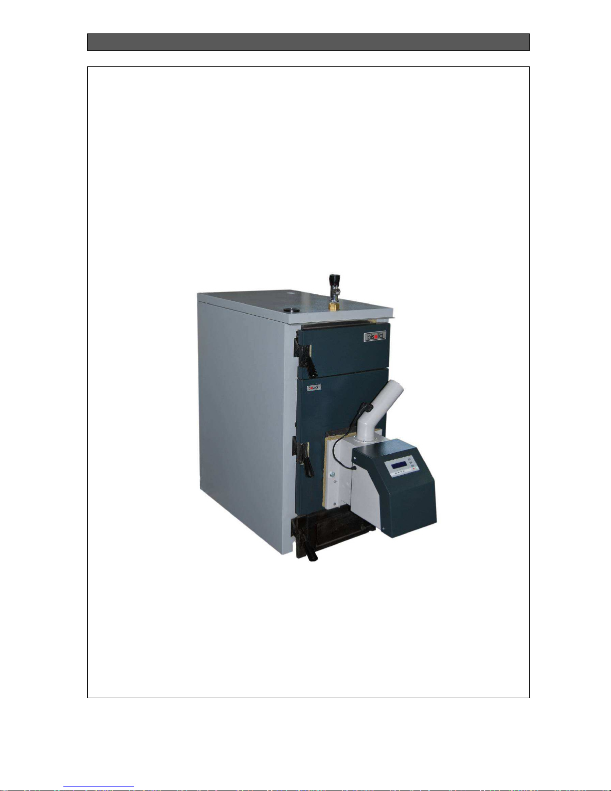
INSTALLATION, OPERATION AND MAINTENANCE MANUAL
BiSolid Comfort
30.1.2013 г. 19:38
OM-BSCV00/08/2012/EN
MANUAL
FOR INSTALLATION, OPERATION AND MAINTENANCE OF HOT
WATER SOLID FUEL BOILER FROM SERIES BISOLD
COMFORT 03/04/05
Page 2

INSTALLATION, OPERATION AND MAINTENANCE MANUAL
BiSolid Comfort OM-BSCV00/08/2012/EN
2
CONTENT page.
1. IMPORTANT INFORMATION ABOUT SYSTEM OPERATION 3
1.1. SAFETY INSTRUCTIONS 3
1.2. PURPOSE OF THE BOILER 4
1.3. FUEL 4
1.4. BOILER OVERALL DIMENSIONS 5
1.5. BOILERS TECHNICAL DATA 5
2. INTRODUCTION 8
2.1. BOILER GENERAL REQUIREMENTS 8
2.2. ENSURING PEOPLE AND EQUIPMENT SAFETY 9
2.3. PRESSURE LOSSES 9
3. OPERATION INSTRUCTIONS 11
3.1. OVERALL CHARACTERISTICS OF HOT WATER BOILER FROM BISOLID
COMFORT SERIES 11
3.2. SAFETY AND CONTROL DEVICES 11
4. BOILER INITIALIZATION TO OPERATION 16
4.1. BOILER CHECK-UPS BEFORE INITIALIZATION FOR OPERATION 16
4.2. FILLING AND DRAINING THE HEATING SYSTEM 16
5. BOILER OPERATION AND CONTROL WITH WOOD LOGS 17
5.1. BOILER FIRING 17
5.2. HEATING WATER TEMPERATURE ADJUSTMENT 17
5.3. REFUELING THE BOILER 17
5.4. BOILER HEATING MODE DURING THE NIGHT 18
5.5. CLEANING THE ASH 18
5.6. CONDENSATION AND TARS 18
5.7. BOILER SWITCH OFF 18
5.8. BOILER SHORT-TERM SWITCH OFF 18
5.9. BOILER LONG-TERM SWITCH OFF 19
5.10. BOILER MAINTENANCE 19
5.11. BOILER CLEANING 20
5.12. BOILER REPAIR 20
5.13. WARRANTY AND WARRANTY CONDITIONS 20
5.14. BOILER PACKAGE KIT AT DELIVERY 20
6. BOILER OPERATION AND CONTROLS WITH WOOD PELLETS 22
6.1. BOILER FIRING 22
6.2. BOILER SWITCH OFF 23
6.3. BOILER SERVICING 24
6.4. BOILER CLEANING AND MAINTENANCE 24
6.5. BOILER REPAIR 24
6.6. BOILER CONTROL PANEL 24
6.7. BOILER WITH PELLET BURNER WIRING DIAGRAM 26
6.8. CONTROL PANEL WITH CONNECTORS FOR PELLET BURNER 27
7. BOILER INSTALLATION INSTRUCTIONS 29
7.1. BOILER INSTALLATION – OVERAL INFORMATION 29
7.2. BOILER WATER REQUIREMENTS 30
7.3. BOILER POSITIONING 30
7.4. MINIMUM DISTANCES 31
7.5. POSITIONING IN THE BOILER ROOM 31
7.6. INSTALLATION PROCEDURE 32
7.7. BOILER SPARE PARTS 33
7.8. BOILER OPERATION WITH ACCUMULATING TANK 35
7.9. TRANSPORTATION AND STORAGE 35
7.10. FLUE OUTLET PIPELINE INSTALLATION 36
7.11. CHIMNEYS AND ADVICES FOR CONNECTING TO CHIMNEYS 37
8. TROUBLESHOOTING 39
Page 3

INSTALLATION, OPERATION AND MAINTENANCE MANUAL
BiSolid Comfort OM-BSCV00/08/2012/EN
3
1. IMPORTANT INFORMATION ABOUT SYSTEM
OPERATION
Dear BiSolid Comfort 03/04/05 hot water boiler owners,
We would like to congratulate you for your new ecological boiler system. By purchasing this
quality product from the manufacturer you have chosen a system that ensures higher comfort
level and optimized fuel consumption in environmentally protecting way and natural resource
saving. Your hot water boiler is manufactured under strict ISO 9001 standards.
On the next pages we have introduced specific information and important advices about the
system operation, its functions and methods of maintenance. Please pay special attention to
this manual. Good knowledge of this document content will give you the pleasure of long-term
and trouble-free operation of the system.
We wish you all the best with Your Bisolid BiSolid Comfort boiler!
1.1. SAFETY INSTRUCTIONS
The hot water boiler from series BiSolid Saver and its accessories correspond to all applicable
directions for safety techniques. Your hot water boiler and all of its accessories operate under
variable electricity 220-230 V. Improper electrical installation or repair may endanger user’s life
from electrical shock. Installation works must be performed only by qualified technicians.
This manual is intended for authorized servicing specialists only. It is important to know that:
Works on the heating installation should be performed only by technicians who had
acquired such rights by law.
Works on the electrical installation should be performed by qualified electricians only.
Initial operation start up including installation visual checks, adjustments and starting
must be performed by the manufacturer authorized personal.
Legal provisions
While operating with the appliance please observe:
Legal provisions for safety techniques.
Legal provisions for environment protection.
Provisions for proper installation.
Applicable provisions of European community.
Safety instructions
Please observe these safety instructions in order to prevent the people from
risks and harms, as well as damage to properties and environment.
Safety instructions explanation.
Please exude attention to the following symbols in this manual:
Danger
This symbol warns for harmful risks or danger to people.
Warning
This symbol warns for risks of damage to properties and environment.
Page 4

INSTALLATION, OPERATION AND MAINTENANCE MANUAL
BiSolid Comfort OM-BSCV00/08/2012/EN
4
Direction
Information marked with this symbol contains additional data.
Works or activities for setting the appliance in proper technical working order
Warning
Repairs of constructional elements which functions are related to the technical
safety may compromise the safely operation of the installation. Damaged or
faulty elements must be replaced with genuine spare parts provided by the
manufacturer.
User behavior when smells flue gas smoke
Danger
Intake of flue gas may lead to life-threatening or harmful poisoning. In case of
danger:
Switch off the heating installation.
Ventilate the place where the installation is positioned.
Close all doors to living premises.
1.2. PURPOSE OF THE BOILER
The hot water boiler from series BiSolid Comfort 03/04/05 are cast-iron section boilers for
firing wood pellets or wood logs. The hot water boilers are designated for heating of small
domestic and company dwellings, as well as for hot domestic water.
Hot water boilers from BiSolid Comfort 03/04/05 series and its standard equipped pellet burner
from BiSolid GP series provides opportunity for quick and easy change of the used fuel type –
wood logs or wood pellets, according to the user specific needs.
1.3. FUEL
Your boiler from BiSolid Comfort 03/04/05 series is designed to utilize the following main fuels:
Chopped firewood with maximum diameter 40-100 mm. The wood logs length depends
on the boiler’s number of sections.
The wood logs must be stored in dry place.
To reach the boiler nominal output, the water content in the firewood should not
exceed 20%.
The boiler has to be refueled manually.
The boilers from series BiSolid Comfort 03/04/05 are able to utilize wood pellets according to
standard EN 14961-2, category ENplus-A1 with the following characteristics:
Page 5
INSTALLATION, OPERATION AND MAINTENANCE MANUAL
BiSolid Comfort OM-BSCV00/08/2012/EN
5
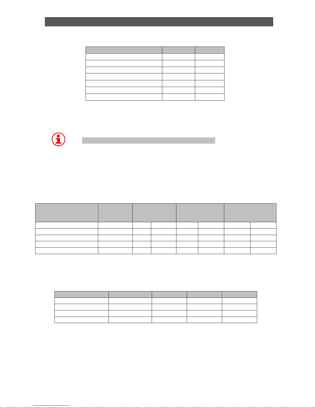
Table 1. Wood pellets main parameters.
Parameter Dimension
Value
Diameter mm 6;8
Length mm 3.5-40
Water content % 10
Ash content % 0.7
Mechanical durability % 97.5
Caloricity MJ/kg 16.5
Bulk density kg/m3 600
Wood pellets must be stored in dry premises, so they can be transported without problems
and also in order to achieve trouble-free operation with optimum combustion and maximum
efficiency.
Warning
The boiler is not designed for firing every type of wastes.
1.4. BOILER OVERALL DIMENSIONS
Overall dimensions of boilers from BiSolid Comfort 03/04/05 series are presented in Table 2.
Table 2. Overall dimensions of the boilers.
Description Dimension Comfort 03
Comfort 04
Comfort 05
Number of sections Pcs 3 3 4 4 5 5
Fuel - Wood Pellets Wood Pellets Wood pellets
Length mm 636 976 736 1076 836 1176
Height mm 1053 1053 1053 1053
1053
1053
Width mm 490 490 490 490 490 490
Dimensions of the boiler, together with its package, from BiSolid Comfort 03/04/05 series are
presented in Table 3.
Table 3. Dimensions of the boiler with package.
Description Dimension Comfort 03 Comfort 04 Comfort 05
Number of sections Pcs 3 4 5
Length mm 680 780 870
Height mm 1097 1097 1097
Width mm 534 534 534
1.5. BOILERS TECHNICAL DATA
The boilers from BiSolid Comfort 03/04/05 series are specialized for firing wood logs and
wood pellets. The cast-iron construction of the boiler guarantees long-term and reliable
operation of the appliance and with pellet burner BiSolid GP high efficiency and low levels of
Page 6
INSTALLATION, OPERATION AND MAINTENANCE MANUAL
BiSolid Comfort OM-BSCV00/08/2012/EN
6
harmful emissions released into the atmosphere. The boilers are designed for heating one or
two floor single-family houses or small company buildings, as well as for heating hot domestic
water.
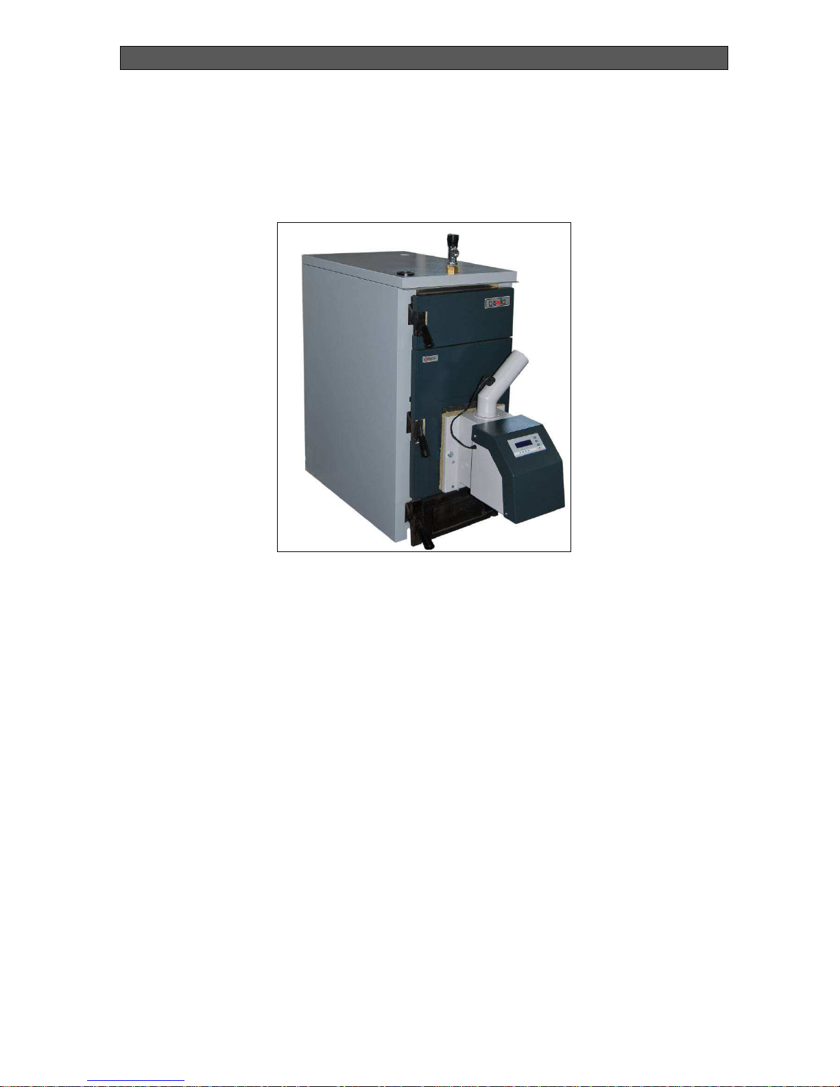
Outer view of hot water boiler from series BiSolid Comfort is presented in Figure 1.
Figure 1. Outer view of hot water boiler BiSolid Comfort.
The main advantages of the boilers from series BiSolid Comfort 03/04/05 are:
The pellet burners from series BiSolid GP are fully automated – ignition, flame control,
combustion chamber blowing. They are also equipped with intuitive LCD display for
easy operation.
Automatic adjustment of fresh air and fuel feed rates according to the selected
operating temperature, which feature provides high efficiency of the appliance at
minimum fuel consumption.
The combustion chamber of the burner is made from fire resistance steel, which
guarantees reliable and long-term operation.
Automatic modulation of the burning process decreasing the number of stops and
ignitions, respectively fuel and electricity consumption.
Availability for wide range regulation of the heat carrier (water) temperature.
Availability for operation with room thermostat and weekly programmer.
Circulations pump control according to the heat carrier (water) temperature.
Availability for control of extraction fan.
Self operation optimization depending on the building and system inertia.
Quiet operation and low electric power consumption.
Protection from back-fire and from heat carrier (water) freezing.
Table 4 presents technical data of hot water boiler from series BiSolid Comfort 03/04/05
operating with wood logs and wood pellets.
Page 7

INSTALLATION, OPERATION AND MAINTENANCE MANUAL
BiSolid Comfort OM-BSCV00/08/2012/EN
7
Table 4. Technical data of hot water boiler from series BiSolid Comfort03/04/05.
Description
Dimension Comfort 03
Comfort 04
Comfort 05
Number of sections pcs. 3 3 4 4 5 5
Fuel - Wood Pellets Wood Pellets Wood Pellets
Wood pellets category
according to EN 14961-2
-
ENplus-A1
ENplus-A1 ENplus-A1
Nominal heating output kW 20 18 25 24 32 30
Working pressure МPa 0.4 0.4
0.4
0.4
0.4
0.4
Fuel consumption at
nominal heating output
kg/h 9.6 4.2 12.2 5.6 15.6 7.0
Chimney draught Ра 15-20 15-20 15-20 15-20 15-20
15-20
Efficiency % 75-81
90 75-80 89 75-80 89
Boiler water volume l 19.4 19.4 23.8 23.8 28.2 28.2
Fuel hopper volume l 33.7 33.7 49.0 49.0 64.3 64.3
Weight kg 187 203 221 237 255 271
Length mm 636 976 736 1076 836 1176
Height mm 1053 1053 1053 1053
1053
1053
Width mm 490 490 490 490 490 490
Page 8

INSTALLATION, OPERATION AND MAINTENANCE MANUAL
BiSolid Comfort OM-BSCV00/08/2012/EN
8
2. INTRODUCTION
2.1. BOILER GENERAL REQUIREMENTS
The boiler and its accompanying equipment must be installed and used in accordance to the
designed heating installation, all applicable legal norms, technical standards and manufacturer
instructions. The boiler should be used only for the subscribed purposes.
The boiler must be installed only for the purposes for which is designed. If the boiler is
delivered and installed to the customer by the same person, then the whole accompanying
documentation must be provided as well (especially the user manual book). The boiler’s
genuine package should be kept until its initial operation start up, in case the boiler should be
transported again.
After installation the boiler operation must be initiated by servicing organization, authorized by
the manufacturer.
The boiler corresponds to the applicable EU legal provisions. If the boiler should be used in
countries outside the EU, all deviations from local laws and legal provisions must be identified
and corrected.
In case of faults in the boiler please contact a servicing organization authorized by the
manufacturer. Every incompetent intervention might damage the boiler (and possibly the
accompanying equipment).
The servicing technician initializing the boiler start up for first time must show the customer all
of its main components, different boiler systems and how to control the boiler. The technician
must present the boiler’s safety elements and signalization, and respectively the relevant user
reaction. If the boiler is delivered and installed to the customer by the same person, then he
must ensure that boiler’s genuine package is kept, in case the boiler should be transported
again.
Please check the delivery of the boiler’s standard accompanying equipment.
Please check if the delivered model and type of the boiler corresponds to the usage
requirements.
If you are not sure how to manage the boiler, please carefully read the relevant instructions in
this manual for operation and installation, and respectively continue as prescribed.
Please never take/stick off or damage the marks and signs on the boiler. Please keep the
boiler genuine package until its initialization to operation, in case the boiler should be
transported again.
If doing a boiler repair, you must always use genuine spare parts only!
It is forbidden to make any changes to the internal installation of the boiler or to change
anything in any way.
Page 9

INSTALLATION, OPERATION AND MAINTENANCE MANUAL
BiSolid Comfort OM-BSCV00/08/2012/EN
9
At the end of the boiler’s life cycle, it should be packed together with its parts and disposed in
an environmentally safe way.
The manufacture company is not responsible for damage or harms caused by non-compliance
with:
Terms and conditions stated in this manual for operation and installation.
Applicable standards and legal provisions.
Procedures for installation and operation.
Terms and conditions presented in the product warranty card.
Situations which are possible to occur in real-time practice and precaution measures that
should be taken:
Switch off the boiler if there are any flammable or explosive vapors in the boiler room,
that may mix with the ambient air which is fed for firing in the boiler (for example from
paint while painting, spraying or laying molten substances, gas leakage, etc.).
If it is necessary to drain the water out of the boiler or from the entire system, as the
water should not be dangerously hot.
If there is any leakage from the boiler’s heat-exchanger or when the heat-exchanger is
choked up, do not try to start the boiler until normal operation conditions are recovered.
2.2. ENSURING PEOPLE AND EQUIPMENT SAFETY
The boiler and all of its parts are in compliance with the safety requirements of the relevant EU
legal regulations.
In order to install and operate the boiler in real-time conditions and in compliance with its
usage designation (stated below only as usage), is necessary also to observe the additional
requirements, as most important of them (those that should not be missed) are presented in
the relevant regulation documents. In addition to the above mentioned documents for the
usage of the boiler it is also necessary to comply with this operation and installation manual
and the product accompanying documentation supplied by the manufacture company.
Any intervention over the boiler’s operation from children and persons under the influence of
narcotic substances, psychiatric abnormalities and etc., must be prevented.
2.3. PRESSURE LOSSES
The pressure losses in the boiler’s combustion chamber, depending on the burning air supply,
are presented in Figure 2.
Page 10

INSTALLATION, OPERATION AND MAINTENANCE MANUAL
BiSolid Comfort OM-BSCV00/08/2012/EN
10
Figure 2. Pressure losses in the combustion chamber.
Page 11

INSTALLATION, OPERATION AND MAINTENANCE MANUAL
BiSolid Comfort OM-BSCV00/08/2012/EN
11
3. OPERATION INSTRUCTIONS
3.1. OVERALL CHARACTERISTICS OF HOT WATER BOILER
FROM BISOLID COMFORT SERIES
The solid fuel boilers from BiSolid Comfort 03/04/05 series are designed for heating of
domestic and industrial buildings.
Preconditions for proper functioning of the hot water boiler are not only its professional
installation, but also the needed chimney draught and its correct operation.
The solid fuel hot water boiler from Bisolid Comfort series is designated for heating systems
which are suitable for systems with forced water circulations.
The hot water boilers from series BiSolid Comfort are offered in three output models (defined
by the number of sections: 3, 4 and 5) with heating capacity from 18 to 32 kW.
The cast-iron boiler body consists of sections and serves as combustion chamber (including
for flue gas extraction) and in the same time as water heat-exchanger. There are three types
of sections - integrated front and rear and from 1 to 3 middle sections (same type), which are
between them. The boiler body required size is built during the assembly (combustion
chamber and water heat-exchanger), with a suitable number of sections. The assembled
boiler body is equipped with the necessary pipe elements for connecting to the water-supply
system.
The boiler body is also equipped with brackets for installation of thermostat sensors and
brackets on the legs for fixing the boiler to a floor base. Steel plate covers are mounted on the
boiler body and are filled inside with heat-isolation.
In order to guarantee the boiler’s proper operation and that it will operate economically, it is
important to know that its nominal heating output is equal to the heat losses of the heated
premises.
Choosing a boiler with insufficient heating output will lead to unadequate heating of the
premises and by such terms not providing of the heating comfort.
Choosing a boiler with unnecessarily high heating output will lead to terms in which the boiler
will not operate at its full ouput power and as consequences to excesive condensation and tar
deposits.
3.2. SAFETY AND CONTROL DEVICES
The hot water solid fuel boilers from series BiSolid Comfort 03/04/05 are equipped with two
main control components:
Chimney (flue) flap.
Thermo-regulating valve (TRV).
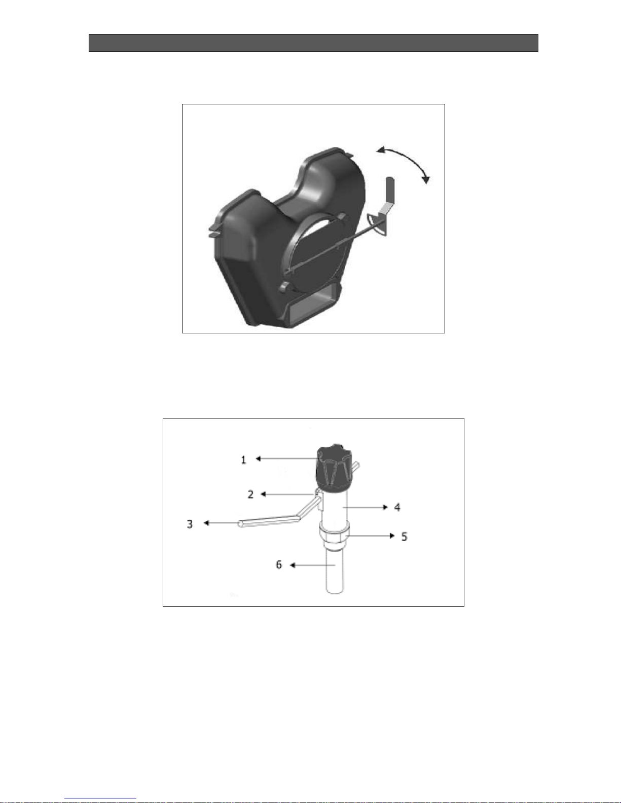
The chimney flap (Figure 3) is element which supports the chimney draught regulation, i.e.
exctracting the flue gasses to the chimney. The flap is situated in the boiler’s flue back side
and is controlled manually.
Page 12
INSTALLATION, OPERATION AND MAINTENANCE MANUAL
BiSolid Comfort OM-BSCV00/08/2012/EN
12
Figure 3.Chimney (flue) flap for draught regulation.
Another element for regulation of the boiler draught is the thermo-regulating valve (Figure 4).
The regulator is situated on the cast-iron body exit. It regulates the primary air quantity, used
for firing, under the boiler fire-grate by opening or closing a flap, situated on the ash-tray door.
Figure 4. Thermo-regulating valve (TRV).
1. Regulator head
2. Holder
3. Handle
4. Regulator body
5. Hex key
6. Hollow shaft
Page 13
INSTALLATION, OPERATION AND MAINTENANCE MANUAL
BiSolid Comfort OM-BSCV00/08/2012/EN
13
Danger
When installing the elements for safety and control please do not forget that all
installation works must comply with the safety labor principles. If thermoregulation valve or other safety element replacement is necessary, please use
the recommended devices. In case of using any other type of devices you
should ask the supplier first. The thermo-regulating valve must be checked by
authorized specialist once per year.
The change of the flap position controls the burning intensity and by that the boiler heating
output (when operating with wood logs). The thermo-regulating valve is connected to the
control flap by a chain. The chain is connected to the flap in such way that the thermoregulating valve tensioning can be adjusted (Figure 5).
Figure 5. Control flap.
Warning
When the boiler operates with wood pellets the chain must be disconnected
from the flap. The necessary air for firing is supplied by the pellet burner fresh
air fan.
Danger
Keep any objects away from the regulating flap and from the grooves providing
primary air intake.
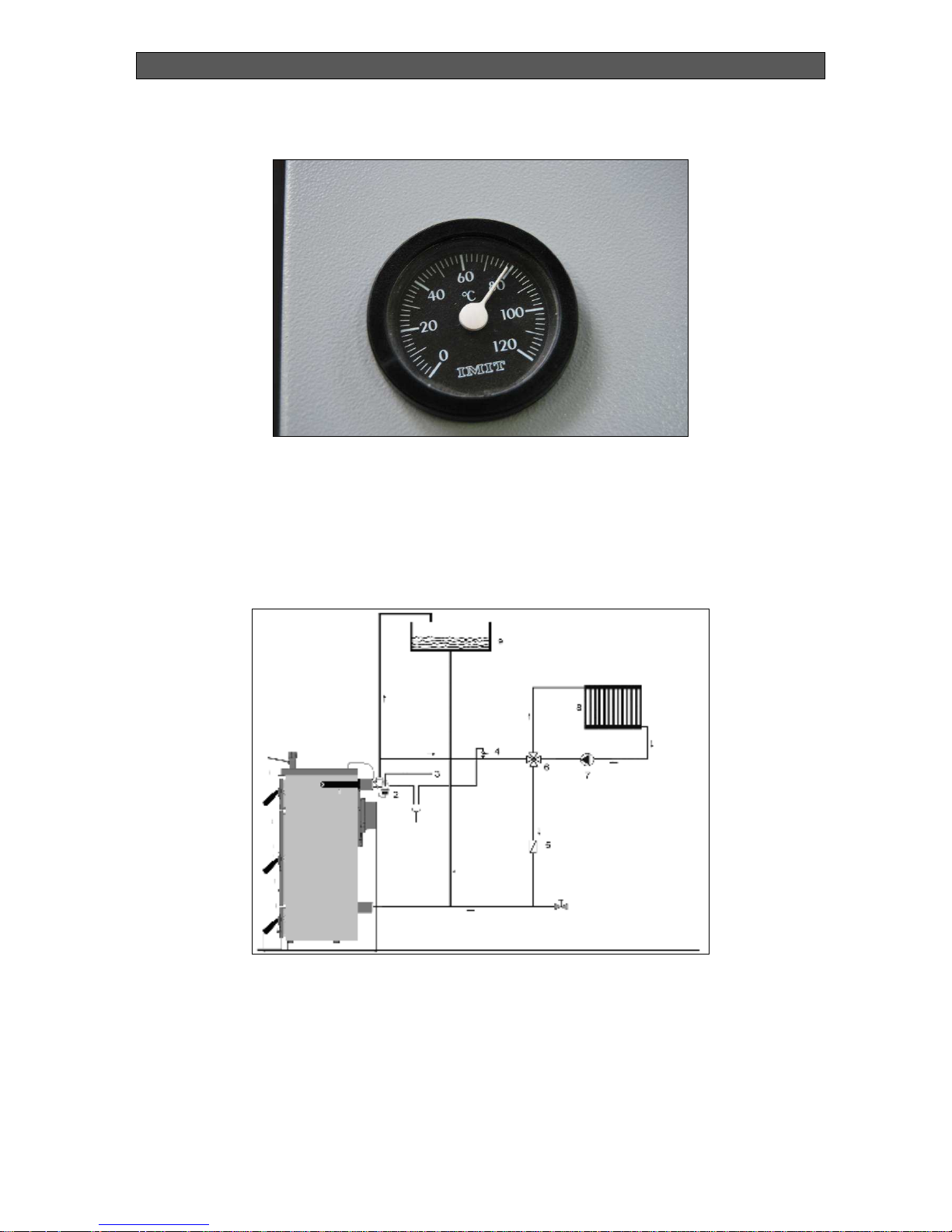
The hot water temperature can be measured by thermometer (Figure 6), which is situated on
the front boiler panel, over the fuel feeding door.
Page 14
INSTALLATION, OPERATION AND MAINTENANCE MANUAL
BiSolid Comfort OM-BSCV00/08/2012/EN
14
Figure 6. Termometer.
Hydraulic scheme
It is presumed that the hydraulic system is opened type and has to be built in accordance to
the following scheme (Figure 7).
Figure 7. Schematic hydraulic diagram.
1. Safety heat-exchanger
2. Safety valve (TS 131, SТС 20)
3. Water supply
4. Safety valve (3 bar - 1/2")
5. Stopping valve
6. Four-way mixing valve
7. Pump
8. Heating device / Heater
9. Open type expansion tank
The open type expansion tank must be installed on the highest place in the entire hydraulic
system.
Page 15

INSTALLATION, OPERATION AND MAINTENANCE MANUAL
BiSolid Comfort OM-BSCV00/08/2012/EN
15
The expansion tank must be chosen properly, complying with the water volume changes
resulting from its heating and cooling.
The expansion tanks and their pipe connection lines must be protected against freezing.
The drain pipe diameter must be chosen properly, so the risk of overfilling to be eliminated.
Page 16

INSTALLATION, OPERATION AND MAINTENANCE MANUAL
BiSolid Comfort OM-BSCV00/08/2012/EN
16
4. BOILER INITIALIZATION TO OPERATION
4.1. BOILER CHECK-UPS BEFORE INITIALIZATION FOR
OPERATION
Before initializing the boiler for operation the service technician must check:
If the installation complies with the project.
Boiler must be filled with water, to be under pressure and to check the entire heating
system for leakages.
Boiler connection to chimney – flue pipe connection lines must be approved by
authorized service technician.
Heating regulators functionality.
Warning
The service technician must train the user how to operate and manage the
boiler and also to fill in the exact start of operation date in the warranty card of
the product.
4.2. FILLING AND DRAINING THE HEATING SYSTEM
The system can be filled or drained with water only if the water corresponds to EN standards
values. The water must be clean, with no color, no suspended particulates, oils and chemically
aggressive and corrosive substances, and also it should not be acid (pH factor must be higher
than 7.0). At first place a comprehensive rinsing of the entire heating system should be
performed.
Warning
Water quantity in the system should not be decreased or drained except in the
cases when the boiler is being repaired or there is risk of freezing. An antifreeze
fluid can be added against freezing, with a volume of 15% from the total liquid
quantity (please see the anti-freezing fluid supplier usage instructions).
Warning
Not fulfilling the above mentioned requirement might result in clogging the heatexchanger of the boiler and cracking the cast-iron sections. During the heating
season the water volume in the heating system must be kept constant. If
refilling with water you must be careful to not intake air into the system. The
circulation water should never be drained out from the boiler or the heating
system, except if it is absolutely necessary, for example when doing repairs and
etc. Draining and refilling the system with water increases the risk of corrosion
and boiling stone (scale).
Warning
Filling or topping up water into the heating system must be done only when the
boiler is cold or cooled, in other case the cast-iron sections of the boiler may
crack.
Page 17

INSTALLATION, OPERATION AND MAINTENANCE MANUAL
BiSolid Comfort OM-BSCV00/08/2012/EN
17
5. BOILER OPERATION AND CONTROL WITH WOOD LOGS
5.1. BOILER FIRING
Before firing a hot water boiler from BiSolid Comfort 03/04/05 series check the manometer and
wether there is enough water in the heating system. Open the stopping valve, located between
the boiler and the heating system. Spread paper over the cleaned fire-grate and then put over
it enough quantity of chopped wood pieces. Open the flue flap and close the fuel feeding door.
Ignite the paper through the ash cleaning door and fully open the regulating flap, located on
the same door. When the fire has ignited enough layer of the main fuel, a smooth burning
should be observed. When the fire has enough power, add more fuel up to the lower edge of
the fuel feeding door.
Ensure equal layer of fuel on the whole boiler depth. When the boiler has reached the needed
heating output, then it is necessary to part or half close the chimney flap, in order ro prevent
exctraction of heat to the chimney.
Danger
Do not start the boiler if it’s not connected to a chimney.
Before starting the boiler check its connection with the chimney.
Check the chimney draught. If it is above the recommended values a
draught regulator has to be installed.
5.2. HEATING WATER TEMPERATURE ADJUSTMENT
When the desired heating water temperature is 60°C, you can heat the water in the boiler for
example with 5°C higher than the desired temperature of 60°C (it is measured by the boiler
thermometer). This is possible if you turn the thermo-regulating valve’s head to 65°C and
check if the regulating chain is streched and the regulating flap is completely closed. This
position of the flap regulating chain can be adjusted by turning the regulating valve’s head.
Then the process of adjustment works out. When the water temperature decreases, the
regulating flap will start to open by the force applied from the chain. When the water
temperature suddenly increases, the regulating flap will start to close. In such way the air fed
in the burning zone can be regulated, respectively the water temperature in the boiler.
5.3. REFUELING THE BOILER
First close the regulating flap, this action will cut the air supply needed for firing in the boiler.
After that, open the chimney (flue) flap completely. Gradually open the fuel feeding door and
wait until all gasses are led out from the burning chamber to the chimney. Only then you can
open the fuel feeding door completely and start to refuel the boiler. After closing the fuel
feeding door, you should again restore the chimney flap position and the regulating flap
function.
Danger
Boiler doors must not be opened when it operates continuously.
When refueling the boiler ensure minimum distance of 5 cm between the
loaded fuel highest point and the combustion chamber top surface.
Page 18

INSTALLATION, OPERATION AND MAINTENANCE MANUAL
BiSolid Comfort OM-BSCV00/08/2012/EN
18
5.4. BOILER HEATING MODE DURING THE NIGHT
This mode is used when you want to keep the fire in the boiler burning, for example during the
night. First scrape all the ash from the combustion chamber, with completely opened chimney
flap. After that refuel the boiler and close the fuel feeding door. After that, close the chimney
and the regulating flaps. This will lead to chimney draught decreasing and will limit the firing air
supply. Then close the rosset for secondary air supply. To restore the needed boiler heating
ouput open the chimney flap and partially open the regulating flap, until reaching the needed
boiler heating output.
5.5. CLEANING THE ASH
The cleaning is performed by removing and emptying the ash-tray, positioned in the ash
drawer under the fire-grate. This action must be performed regularly, in order to prevent ash
depositing and blocking the air supply to the combustion chamber.
5.6. CONDENSATION AND TARS
When firing a cold boiler the water condenses over the walls and flows down in the ash
drawer, which causes doubt that the boiler “leaks”. The condensation will disappear when the
inside walls of the boiler get warmed. When the boiler operates with low water temperature,
usually under 65°C or when the used fuel is wet, then the water condenses in the flue gasses
and the condense leaks down over the cold boiler walls. The low temperature heating mode
reduces the chimney life-time also. Therefore it is recommended to equip the boiler with fourway mixing valve, which guarantees that the inlet water will not be below 50°C. The tar
depositing occurs in similar conditions (lack of air for firing, boiler clogging). To prevent from
condensation and tars we recommend to start the boiler at water temperatures higher than
65°C or to choose a boiler which corresponds to the needed heating output. The oversized
boiler operates inefficiently, because it has to operate at low temperatures.
Warning
Condensation is possible at initial boiler firing. This should not embarrass the
user, because it is normal event – especially when firing wood with higher water
content. The boiler “dries” when it reaches normal operation mode.
5.7. BOILER SWITCH OFF
We do not recommend you to accelerate the burning process in the boiler. The fuel must burn
completely by itself over the fire-grate.
5.8. BOILER SHORT-TERM SWITCH OFF
After switching off the boiler, clean it, take out all burned wastes, empty its ash-tray, clean the
contact surfaces of the feeding door and the ash drawer, and after that close the boiler’s fuel
feeding and ash drawer doors.
Page 19

INSTALLATION, OPERATION AND MAINTENANCE MANUAL
BiSolid Comfort OM-BSCV00/08/2012/EN
19
5.9. BOILER LONG-TERM SWITCH OFF
When switching the boiler off for long period of time (at the end of the heating season), it must
be completely cleaned from all unburned accumulations (soot, ash and deposits). Otherwise
the accumulation of moisture in the unburned gasses leads to excessive boiler corrosion.
Warning
The boiler can be operated only by adult people who are well introduced with the
current manual for operation.
Switch off the boiler every time when there is any (even momentary) danger by the
presence of flammable or explosive vapors situated in the same room from which
the boiler intakes air for burning (for example painting paint, spraying or laying
molten substances, gas leakage, etc.).
Boiler initial firing with explosive substances is strictly forbidden.
Boiler overheating is forbidden.
The boiler and the chimney have to be completely cleaned at the end of the heating
season. Also grease all hinges, chimney flap mechanism and other moving parts.
5.10. BOILER MAINTENANCE
Maintenance of the boilers from series BiSolid Comfort 03/04/05 has to be performed daily,
periodically or early.
During the daily maintenance the user must clean the unburned residues in the combustion
chamber, to clean the ash gathered in the combustion chamber and to dump the ash from the
drawer.
It is important that the user performs periodical maintenance of the appliances, in order to
achieve effective usage, prevention of possible problems with its operation and optimum boiler
life cycle. We recommend periodical check on every 3 months. Such checks have to be
performed by authorized servicing technicians and should include the following activities:
Check boiler’s combustion chamber and flue pipe, including the chimney. They should
be cleaned if necessary.
Check for leakages of incoming or outgoing water, in and out of the boiler, water pipe
links as well.
Check valves, fittings and accessories.
Check circulation pumps.
Visual check of the fire-grate.
Perform operation control check for safety of the hydraulic system and the boiler.
The yearly maintenance (prophylaxis) of the boiler must be performed only by authorized
technicians, before the start of the heating season. Before calling the servicing technicians the
user has to provide already cleaned flue pipes and chimney. During the yearly prophylaxis the
authorized technicians perform the following checks and activities:
Position of the combustion chamber shaft, isolation and isolation ropes.
Boiler test at operating pressure for adjustment of the burning, by measuring flue gas
parameters if necessary.
Check and clean the boiler’s fire-grate and surfaces from soot and ash.
Test boiler connections for leakages.
Check fittings including muffs, mixing valves, pressure valves for reliability.
Page 20

INSTALLATION, OPERATION AND MAINTENANCE MANUAL
BiSolid Comfort OM-BSCV00/08/2012/EN
20
Test and if necessary clean the water filter.
Check expansion tank (buffer) and clean it if necessary.
Test pressure sensor. Clean or replace it if necessary.
Perform operation control check for safety of the hydraulic system and the boiler.
5.11. BOILER CLEANING
After continues operation of the boiler amounts of soot and ash accumulate to its walls, mainly
over the heat-exchanger sections and the flue outlet, which decrease the heat-exchanging
rate and the boiler heating ouput. The amounts of soot and tar depend on the operation
conditions and the types of used fuel. This may also lead to inadequate chimney draught.
Boiler cleaning has to be performed regularly, at least once per month, usually by using steel
brush through opened boiler door.
All inside walls of the boiler in the combustion chamber and the flue gasses passage channels
must be cleaned. If there is bigger quantity of tars over the combustion chamber inside walls,
then it must be removed by using a scraper or burned by firing hard wood at maximum
operation temperature.
Direction
The ash must be stored (the ash has to be taken out by using gloves) in
fireproof reliable containers and to be transported to opened spaces. Other
garbage or wastes should not be stored in these containers.
5.12. BOILER REPAIR
The boiler must be repaired only by authorized servicing technician or servicing organization.
The user or owner is allowed to perform only normal maintenance and to replace only a few
parts, for example sealing of insulating rope.
Warning
Always use only genuine spare parts when repairing the boiler.
5.13. WARRANTY AND WARRANTY CONDITIONS
The hot water boilers from series BiSolid Comfort 03/04/05 are available with warranty,
presented in the warranty card and the operation and installation manual (part introduction,
boiler installation).
5.14. BOILER PACKAGE KIT AT DELIVERY
All hot water boilers from series BiSolid Comfort 03/04/05 are delivered fully assembled and
functionality tested. The full accompanying delivery kit for the boilers is presented in Table 5.
Page 21

INSTALLATION, OPERATION AND MAINTENANCE MANUAL
BiSolid Comfort OM-BSCV00/08/2012/EN
21
Table 5. Delivery kit of boiler BiSolid Comfort.
Pos.
Description Pcs
1 Hot water boiler Bisolid Comort 1
2 Wood pellet burner Bisolid GP 1
3 Pellet auger Bisolid 1
4 Ash-tray 1
5 Electrical control panel 1
6 TRV – thermo-regulating valve 1
7 Cleaning tool – scraper 1
8 Cleaning tool – steel brush 1
9 Operation manual 1
10 Warranty card 1
Page 22

INSTALLATION, OPERATION AND MAINTENANCE MANUAL
BiSolid Comfort OM-BSCV00/08/2012/EN
22
6. BOILER OPERATION AND CONTROLS WITH WOOD
PELLETS
6.1. BOILER FIRING
Before firing the boiler from series BiSolid Comfort 03/04/05 when utilizing wood logs please
comply with the instructions in part 5.1, presented in the current manual for operation.
When operating boilers from series BiSolid Comfort 03/04/05 with wood pellets, the user has
to use the additional front door on which a pellet burner from series Bisolid GP can be
installed. The boilers from series BiSolid Comfort 03/04/05 are equipped with control panel, so
quickly and easily (for less than a minute) you can switch from wood logs to wood pellets and
contrariwise.
The burners from series BiSolid GP can burn wood pellets with diameter ∅ 6-8 mm and
category of wood pellets according to EN 14961-2 - ENplus-A1. Switching the boiler operation
from wood logs to wood pellets must be performed manually, by switching on the installed
pellet burner from series BiSolid GP.
Warning
When operating with wood pellets the user must be familiar in details with the
BiSolid GP pellet burner manual for installation, operation and maintenance.
When the boiler is operating with pellet burner you have to first switch on the main switch
button, which powers the burner control panel.
Warning
It is strongly recommended that starting of the pellet burner is done by the key
“Start” located on the electrical control panel (Please read the operation,
installation and maintenance manual of the pellet burner).
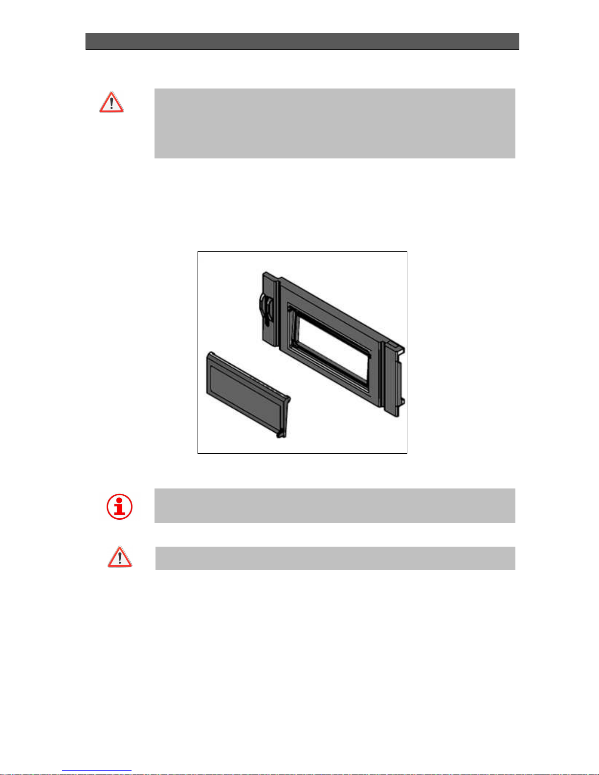
When a hot water boiler from series BiSolid Comfort 03/04/05 operates with wood pellets, the
user must first remove the protection grate located in the front side of the boiler (Figure 8).
Page 23

INSTALLATION, OPERATION AND MAINTENANCE MANUAL
BiSolid Comfort OM-BSCV00/08/2012/EN
23
Figure 8. Boiler protection grate.
Warning
When using a pellet burner from BiSolid GP series, remove the protection grate
by unscrewing its fixing bolts.
Warning
When using wood logs it is obligatory to install the protection grate.
6.2. BOILER SWITCH OFF
Switching off hot water boilers from series BiSolid Comfort 03/04/05 operating with wood logs
must be performed in the appropriate way according to the instructions in parts 5.7, 5.8 and
5.9, presented in the current manual for operation. When operating with wood pellets the pellet
burner switching off must be performed according to the instructions presented in the pellet
burner BiSolid GP manual for operation.
Warning
Stopping the pellet burner is again performed by key “Start” positioned on the
electrical panel. Such stopping ensures burner normal switching off and
complete burning of the remaining pellets. It is not allowed to stop the burner
through its main power supply switch!
Protection
grate
Page 24

INSTALLATION, OPERATION AND MAINTENANCE MANUAL
BiSolid Comfort OM-BSCV00/08/2012/EN
24
6.3. BOILER SERVICING
When servicing hot water boilers from series Comfort 03/04/05 operating with wood logs,
please observe the instructions in part 5.10 from the current manual for operation. When
operating with wood pellets servicing of the pellet burner must be performed according to the
BiSolid GP burner series manual for operation.
6.4. BOILER CLEANING AND MAINTENANCE
When cleaning and maintaining hot water boilers from series BiSolid Comfort 03/04/05
operating with wood logs, please observe the instructions presented in part 5.11 from the
current manual for operation. When operating with wood pellets cleaning of the burner must
be performed in accordance to the BiSolid GP manual for operation.
6.5. BOILER REPAIR
Repairs of hot water boilers form series BiSolid Comfort 03/04/05 operating with wood logs
must be performed according to the instructions presented in part 5.12 from the current
operation manual. When operating with wood pellets repair works must be performed in
accordance to the BiSolid GP pellets burner manual for operation.
6.6. BOILER CONTROL PANEL
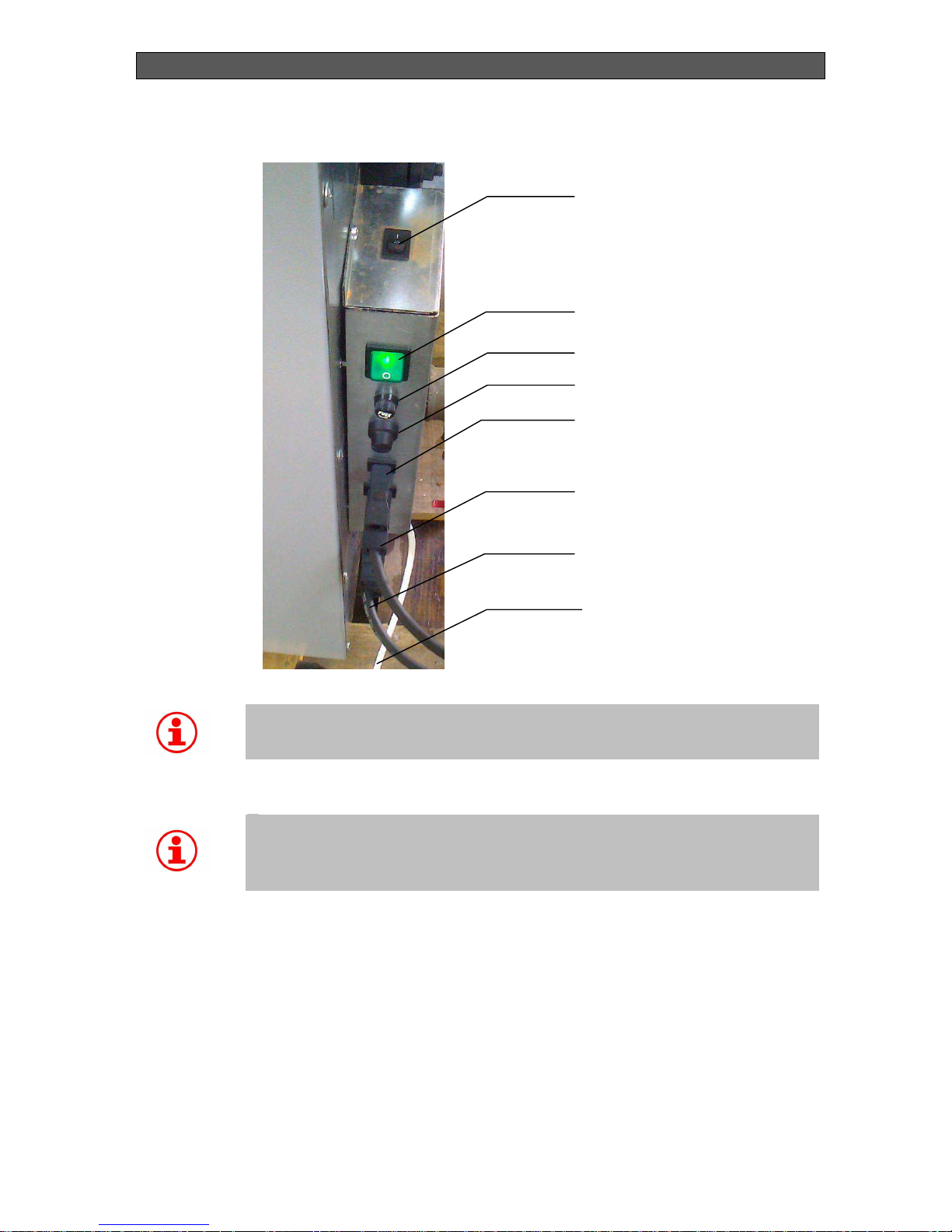
The electrical control panel of boilers BiSolid Comfort 03/04/05, operating with pellet burners
BiSolid GP, is presented in Figure 9.
Page 25
INSTALLATION, OPERATION AND MAINTENANCE MANUAL
BiSolid Comfort OM-BSCV00/08/2012/EN
25
Figure 9. Electrical control panel of the boiler.
Warning
All works and activities over the electrical wiring of the burner or adjustments,
where is necessary to remove its covers and other elements, that protect from
contact with the electrical parts, must be performed by authorized person.
Warning
T
he burner must be connected to the electrical installation of the relevant
appliance (boiler) by observing all safety techiques. The main power supply
cable must be used in complinace with the attached wiring diagram for
connecting to the main power supply and to burner’s control module.
START
POWER – MAIN SWITCH
FUSE, 10A
SAFETY THERMOSTAT
ROOM THERMOSTAT
PELLET BURNER –
POWER SUPPLY
PELLET BURNER & BOILER
COMMUNICATION CABLE
BOILER POWER SUPPLY
CABLE
Page 26
INSTALLATION, OPERATION AND MAINTENANCE MANUAL
BiSolid Comfort OM-BSCV00/08/2012/EN
26
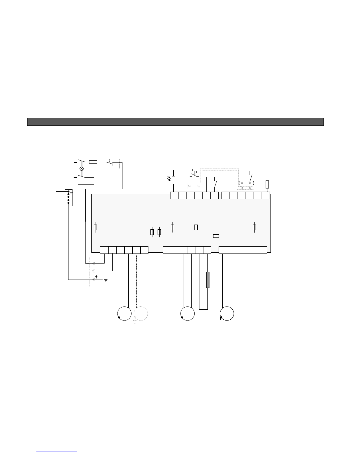
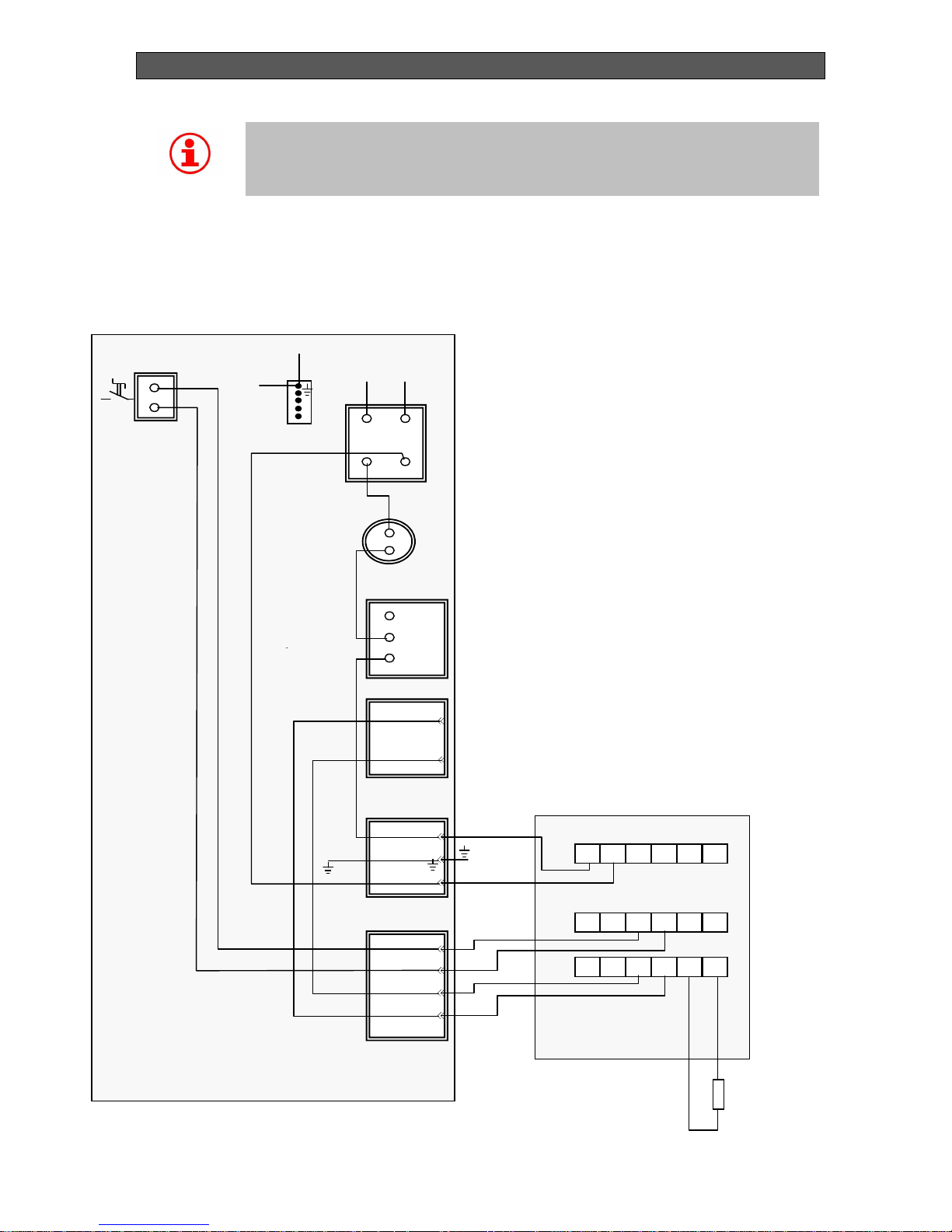
6.7. BOILER WITH PELLET BURNER WIRING DIAGRAM
Figure 10. Boiler with pellet burner – wiring diagram.
Auger
1 2 3 4 5 6
1 2 3 4 5 6 1 2 3 4 5 6
6 5 4 3 2 1 6 5 4 3 2 1
Fresh air
Extactor fan - option
Pump
Ignition
Photo sensor
Start
Back fire
Room
thermostat
Pt 1000
H2O
1100 W
X1
X2
X3
X4
X5
F1
2A
F2
2A
F3
2A
F4
2A
F7
2A
F5
10A
F6
5A
Fan 1
Fan 2
Fan 3
Auger
Ignition
Pump
Cleaning
PE
Connector -
communication
N
220 V
Neutral
L
220 V
Phase
Brown
Gray or blue
Safety thermostat
t – 950C
Connector -
Pellet burner
L1
N
Page 27
INSTALLATION, OPERATION AND MAINTENANCE MANUAL
BiSolid Comfort OM-BSCV00/08/2012/BG
27
Warning
When operating with wood logs or wood pellets do not interrupt the boiler power
supply, because the circulation pump must operate until the boiler cools down.
In all wiring types the circulation pump must always operate when the boiler
looses heat for unloading purposes.
6.8. CONTROL PANEL WITH CONNECTORS FOR PELLET
BURNER
Figure 11. Control panel with connectors for pellet burner wiring diagram.
Pt 1000
PELLET
BURNER
Brown
Gray
POWER
FUSE
10A
Safety
thermostat
220 – 230 VAC,
ROOM
THERMOSTAT
PELLET
BURNER
X1
X5
X4
Start
Room thermostat
Power supply
START
Yellow/green
Connector-
Comunication
Page 28

INSTALLATION, OPERATION AND MAINTENANCE MANUAL
BiSolid Comfort OM-BSCV00/08/2012/EN
28
Warning
Connecting a room thermostat: Before connecting the room thermostat to the
connector (moving part) for ROOM THERMOSTAT (positioned on the back of
the boiler’s side cover panel), remove the factory installed bridge, located in the
connector. Use only room thermostat contact without external voltage! Please
see the wiring diagram!
Page 29

INSTALLATION, OPERATION AND MAINTENANCE MANUAL
BiSolid Comfort OM-BSCV00/08/2012/EN
29
7. BOILER INSTALLATION INSTRUCTIONS
7.1. BOILER INSTALLATION – OVERAL INFORMATION
The hot water boilers from series BiSolid Comfort 03/04/05 must be initianted into operation by
authorized servicing technicians. The existing network of authorized servicing organizations
which comply with this condition is able to take responsibility for all boiler installations, their
initialization in operation and warranty repairs.
The boiler is designed to supply heating systems with pressure up to 400 kPa by using water,
which must compy to the standard requirements (under no circumstances the water can be
acidic, i.e. it must have hydrogen exponent pH>7 and minimum carbon hardness). The heating
system must be designed in such way that the hot water circulates at least through some of
the radiators at all times.
We do not recommend the usage of antifreeze liquids because of their unsuitable properties.
Such liquids have decreased heat-exchanging capabilities, high volume expansion and
harmfull components.
Before final installation, the distribution pipelines of the heating system must be rinsed several
times with water under pressure. In old, already used systems, the rinsing has to be performed
in opposite direction to the heated water circulation. In new systems all radiators have to be
cleaned from erosive materials and rinsed with warm water under pressure.
We recommend installation of precipitant on the boiler entrance (i.e. on the boiler’s hot water
return pipeline). The precipitant should be designed with availability for emptying on regular
intervals, without necessity of draining too much hot water. The precipitant can be combined
with filter, but the filter itself is not enough to secure adequate protection.
Warning
The system must be connected to open type expansion tank, for safety
reasons.
Any of the stopping fittings must not be connected to the inlet or the safety
outlet pipelines.
For increasing the system safety a bypass line must be installed on the inlet
and outlet line of the circulations pump, as presented on the diagrams.
The bypass line valve must be closed when the boiler operates normally.
The bypass line valve can be used when there are problems with the power
supply and must be opened if there is any risk of heating system water
overheating, caused by power supply failure or another problem.
The pipelines diameter installed in the bypass line must be at least equal of the
water supply pipeline.
UPS (uninterruptible power supply) can be used for prevention of power supply
failures.
Warning
All problems (faults) with the boiler caused by clogging with dirt from the heating
system or faults caused by clogging are not covered by the product warranty.
Page 30

INSTALLATION, OPERATION AND MAINTENANCE MANUAL
BiSolid Comfort OM-BSCV00/08/2012/EN
30
Warning
The filter, as well as the precipitant must be checked and cleaned regularly.
7.2. BOILER WATER REQUIREMENTS
The boiler water requirements are presented in the European standards. If the sum of calcium
and magnesium content in the water exceeds 1,8 mmol/l without additional chemical
processing, then for calcareous depostis prevention special measures must be performed (for
example processing with magnetic or electrostatic field).
7.3. BOILER POSITIONING
The hot water boilers from series BiSolid Comfort 03/04/05 can be positioned in rooms that
comply with the acting legal local provisions. The boiler room must have constant fresh air
intake, needed for the burning process. The air has to be clean, without halogen
hydrocarbons, corrosive vapors and should not be too wet and dusty. The room must be
protected against freezing and with no more than 80% relative humidity of the air.
In order to comply with the fire provisions the boiler must be installed:
Over flooring from inflammable material.
Over surface from inflammable material, under-covering the boiler with 20 mm pitch
from every side and covering the entire width of the boiler body.
If the boiler is installed in the basement, we recommend that it is positioned over
fundament with at least 50 mm height, as the boiler is positioned in the middle.
In compliance with the servicing standards it is necessary to leave space with at least 600 mm
length at the boiler front side. The minimum distance between the boiler back and the wall
must be also 600 mm. It is also necessary to leave free space of at least 600 mm between the
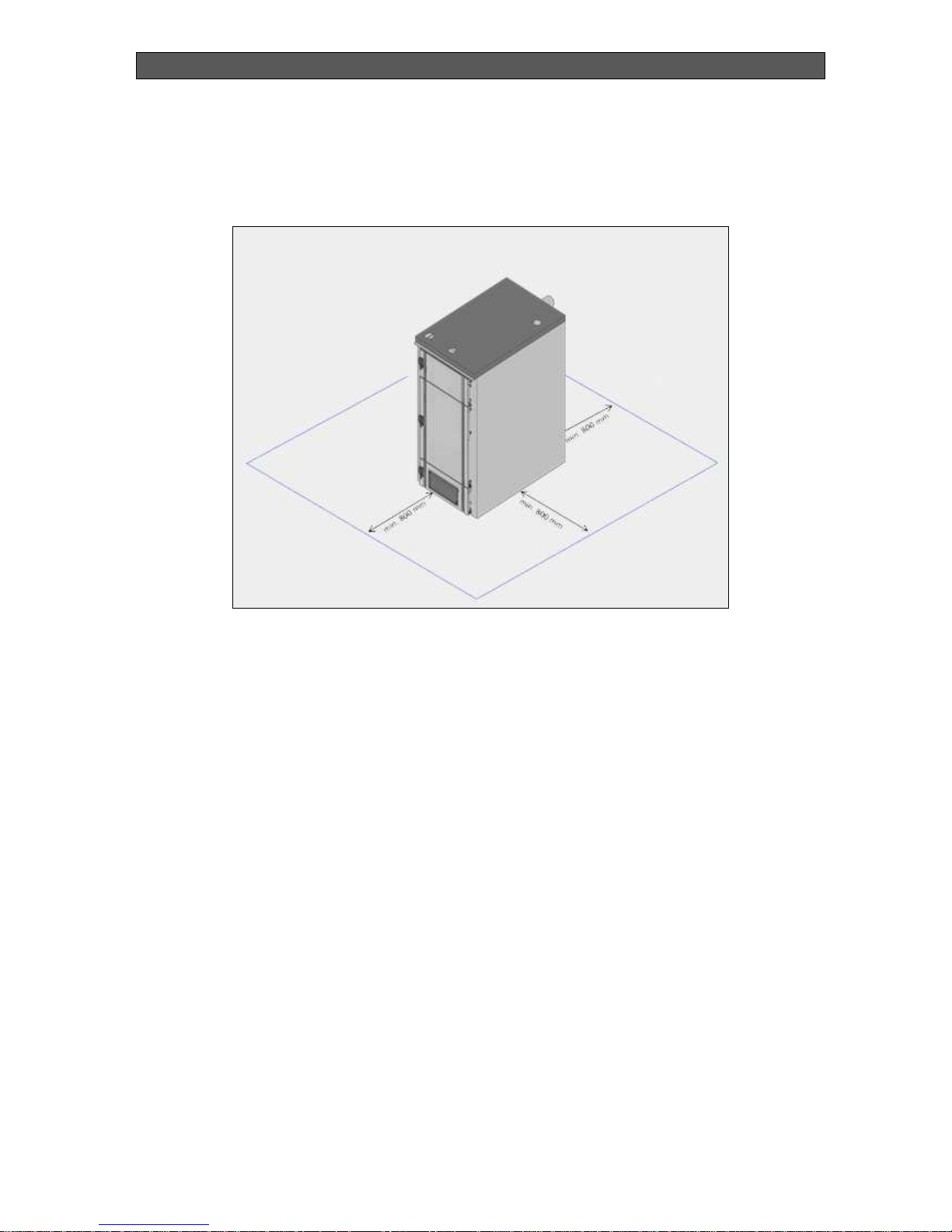
boiler sides and the wall, in order to provide access to the boiler back side. The fuel must not
be positioned close to the boiler, as the minimum distance is at least 800 mm.
If there are two boilers in the room it is not allowed to position any fuel between them. It is
recommended to keep minimum distance of 800 mm between the boiler and the fuel (Figure
12), or to store the fuel in a premise different from the boiler room.
Danger
Do not put flammable materials over the boiler’s top side or near it within the
safety distance.
Page 31
INSTALLATION, OPERATION AND MAINTENANCE MANUAL
BiSolid Comfort OM-BSCV00/08/2012/EN
31
7.4. MINIMUM DISTANCES
Figure 12. Minimum distances between the boiler and the fuel.
7.5. POSITIONING IN THE BOILER ROOM
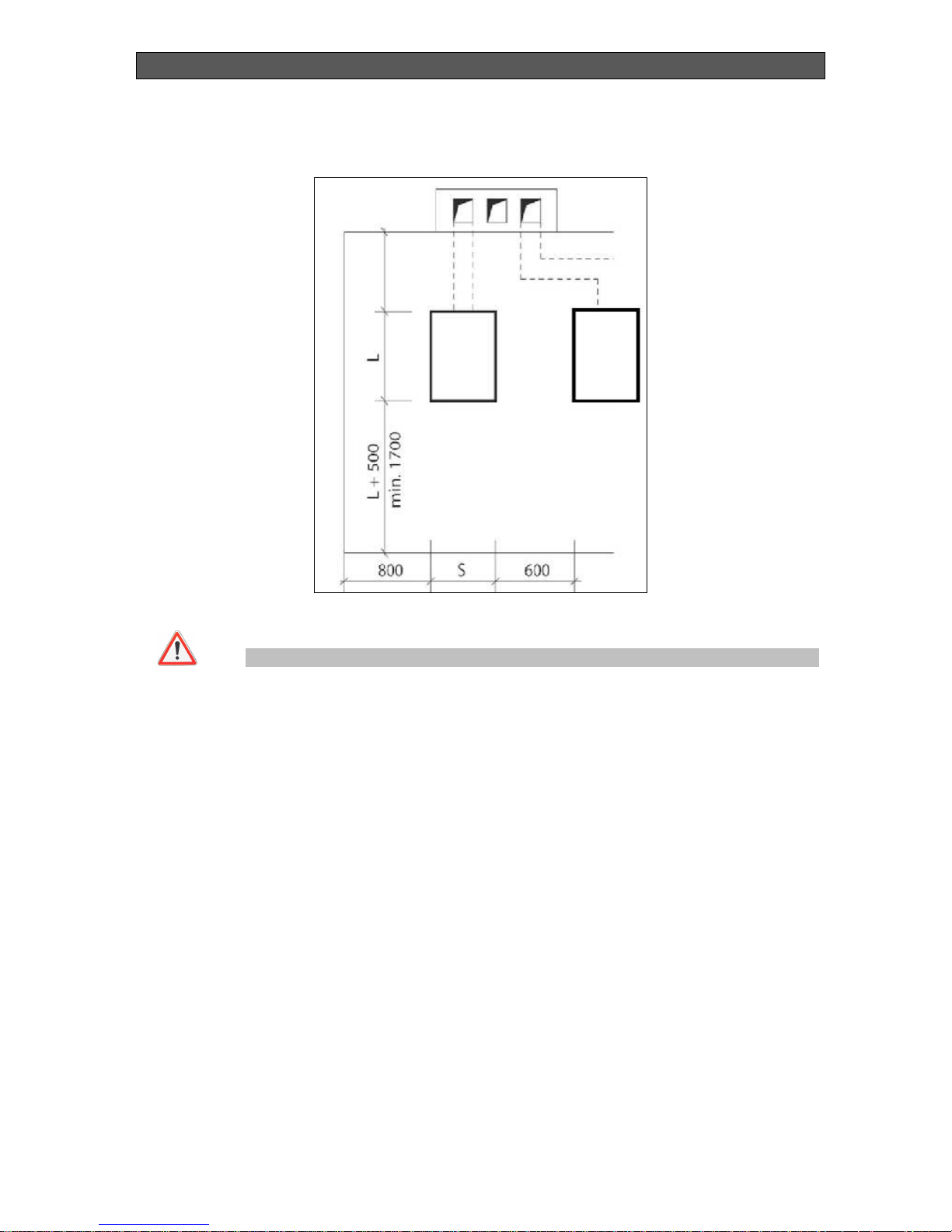
Figure 13 presents the minimum distances which must be observed in order to guarantee safe
operation in the boiler room and availability to perform servicing, cleaning and refueling.
The distance between the boiler front side and the wall has to be at least the boiler length plus
500 mm.
The minimum distances between the boiler from back and side have to be 800 mm, as the
distance in the back is determined by how the boiler is connected to the chimney.
Page 32
INSTALLATION, OPERATION AND MAINTENANCE MANUAL
BiSolid Comfort OM-BSCV00/08/2012/EN
32
Figure 13. Minimum distances in the boiler room.
Danger
When the boiler operates do not touch any hot water pipe lines or flue pipes.
7.6. INSTALLATION PROCEDURE
Position the boiler over inflammable material surface.
Install the temperature safety valve. During its installation make sure that the arrow
direction shows the water flow direction.
After connecting the boiler to the heating system screw the boiler’s filling and draining
stop cocks at its back side.
Install the flue pipe with the boiler’s flue flap for extracting the flue gasses.
Place the flue pipeline end in the chimney connection orifice. The boiler flue diameter
is 150 mm.
Mount the thermo-regulating valve in the orifice at the front section top side.
We recommend installation of hot water stopping valves at the inlet and outlet pipes,
before draining the entire heating system, so they can clean before the filter.
Any stop fittings should be installed between the boiler and the expansion tank.
Page 33
INSTALLATION, OPERATION AND MAINTENANCE MANUAL
BiSolid Comfort OM-BSCV00/08/2012/EN
33
7.7. BOILER SPARE PARTS
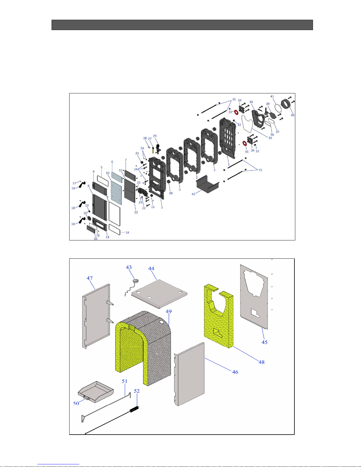
The spare parts for hot water boilers from series BiSolid Comfort 03/04/05 are presented in
Figure 14 and Figure 15.
Figure 14. Spare parts of the boiler.
Figure 15. Spare parts of the boiler.
Page 34

INSTALLATION, OPERATION AND MAINTENANCE MANUAL
BiSolid Comfort OM-BSCV00/08/2012/EN
34
Table 6 presents the list of spare parts for cast iron boilers from series BiSolid Comfort
03/04/05.
Table 6. Spare parts list.
Comfort03 Comfort04 Comfort05
1 Front section SN 060 SN 060 SN 060
2 Middle section SN 050 SN 050 SN 050
3 Back section SN 070 SN 070 SN 070
4 Cleaning door SN 010 SN 010 SN 010
5 Cleaning door insulation rope SN 011 SN 011 SN 011
6 Gleaning door insulation SN 012 SN 012 SN 012
7 Gleaning door insulation covet SN 013 SN 013 SN 013
8 Stocking door SN 022 SN 022 SN 022
9 Stocking door insulation rope SN 015 SN 015 SN 015
10 Stocking door insulation SN 020 SN 020 SN 020
11 Stocking door insulation cover UP SN 021 SN 021 SN 021
12 Stocking door insulation cover DOWN SN 024 SN 024 SN 024
13 Ashtray door SN 040 SN 040 SN 040
14 Ashtray door insulation rope SN 023 SN 023 SN 023
15 Regulation hatch SN 041 SN 041 SN 041
16 Regulation hatch insulation rope SN 041 SN 041 SN 041
17 Notched pin SN 014 SN 014 SN 014
18 Door handle SN 041 SN 041 SN 041
19 Air rosette UP SN 090 SN 090 SN 090
20 Air rosette DOWN SN 092 SN 092 SN 092
21 Stopper 1 1/4" SN 091 SN 091 SN 091
22 Grid lock hinge SN 085 SN 085 SN 085
23 Grid SN 110 SN 110 SN 110
24 Lock hinge SN 123 SN 123 SN 123
25 Grid lock socket SN 140 SN 140 SN 140
26 Door lock cylinder SN 131 SN 131 SN 131
27 Thermostat bulb SN 215 SN 215 SN 215
28 Thermostat bulb segment SN 300 SN 300 SN 300
29 Thermostat regulator SN 400 SN 400 SN 400
30 Nipple SN 401 SN 401 SN 401
31 Connection rods SN 482 SN 483 SN 484
32 Stopper 1/2" SN 403 SN 403 SN 403
33 Flange gasket SN 404 SN 404 SN 404
34 Water inlet-outlet flange SN 405 SN 405 SN 405
35 Chimney adapter insulation rope SN 450 SN 450 SN 450
36 Chimney cleaning door insulation rope SN 451 SN 451 SN 451
37 Chimney cleaning door SN 061 SN 061 SN 061
38 Chimney adapter SN 140 SN 141 SN 141
39 Chimney flap SN 601 SN 603 SN 603
40 Chimney SN 651 SN 653 SN 653
41 Chimney insulation rope SN 701 SN 703 SN 703
42 Middle section cover SN 910 SN 911 SN 912
43 Thermometer SN 160 SN 160 SN 160
44 Top caver panel SN 753 SN 754 SN 755
45 Rear cover panel SN 763 SN 763 SN 763
46 Right side cover panel SN 160 SN 161 SN 161
47 Left side cover panel SN 160 SN 161 SN 161
48 Rear cover panel insulation SN 803 SN 803 SN 803
49 Casting body insulation SN 903 SN 904 SN 905
50 Ashtray SN 773 SN 774 SN 775
51 Mixing rod SN 774 SN 775 SN 776
52 Cleaning brush SN 784 SN 785 SN 786
No. Description
Serial No.
BiSolid
Page 35
INSTALLATION, OPERATION AND MAINTENANCE MANUAL
BiSolid Comfort OM-BSCV00/08/2012/EN
35
7.8. BOILER OPERATION WITH ACCUMULATING TANK
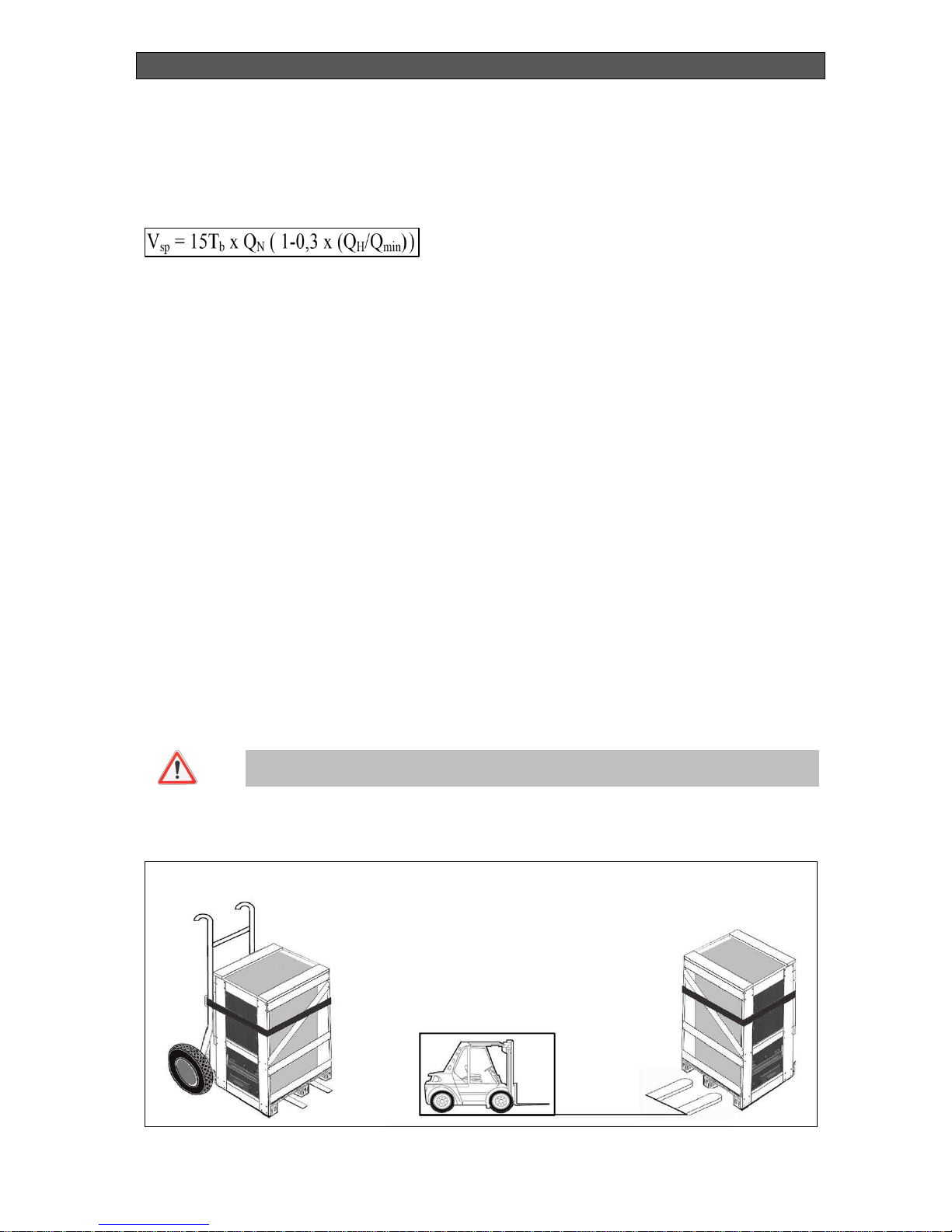
In some cases the heat energy can be delivered to the consuming devices by accumulating
tank. The formula for determining the minimum needed water quantity for accumulation tank is
given below.
Vsp – Volume of the accumulation tank, litters.
QN - Nominal heating output, kW.
Tb - Burning time, h.
QH - Premises heating load, kW.
Q
min
– Minimum heating output, kW.
The heating boiler, which uses not only one fuel type, should operate with accumulation tank,
dimensioned in compliance with the used fuel type requiring highest accumulation tank
volume. Usage of accumulation tank is not necessary when the defined volume is lower than
300 litres.
7.9. TRANSPORTATION AND STORAGE
The boilers for expedition are offered by the manufacturer on a wooden pallet and secured
against moving with cap bolts. The boilers should not be transported in position different from
their base (normal operating position).
It is necessary to ensure at least the minimum conditions for preservation of the boilers during
their storage and transportation.
During transportation and storage the boilers packages and cover panels should not be
pressed.
Danger
The boilers should not be moved or transported without using forklifts, transport
carts or other wheel based transport utilities.
Figure 16. Boiler transportation.
Page 36

INSTALLATION, OPERATION AND MAINTENANCE MANUAL
BiSolid Comfort OM-BSCV00/08/2012/EN
36
7.10. FLUE OUTLET PIPELINE INSTALLATION
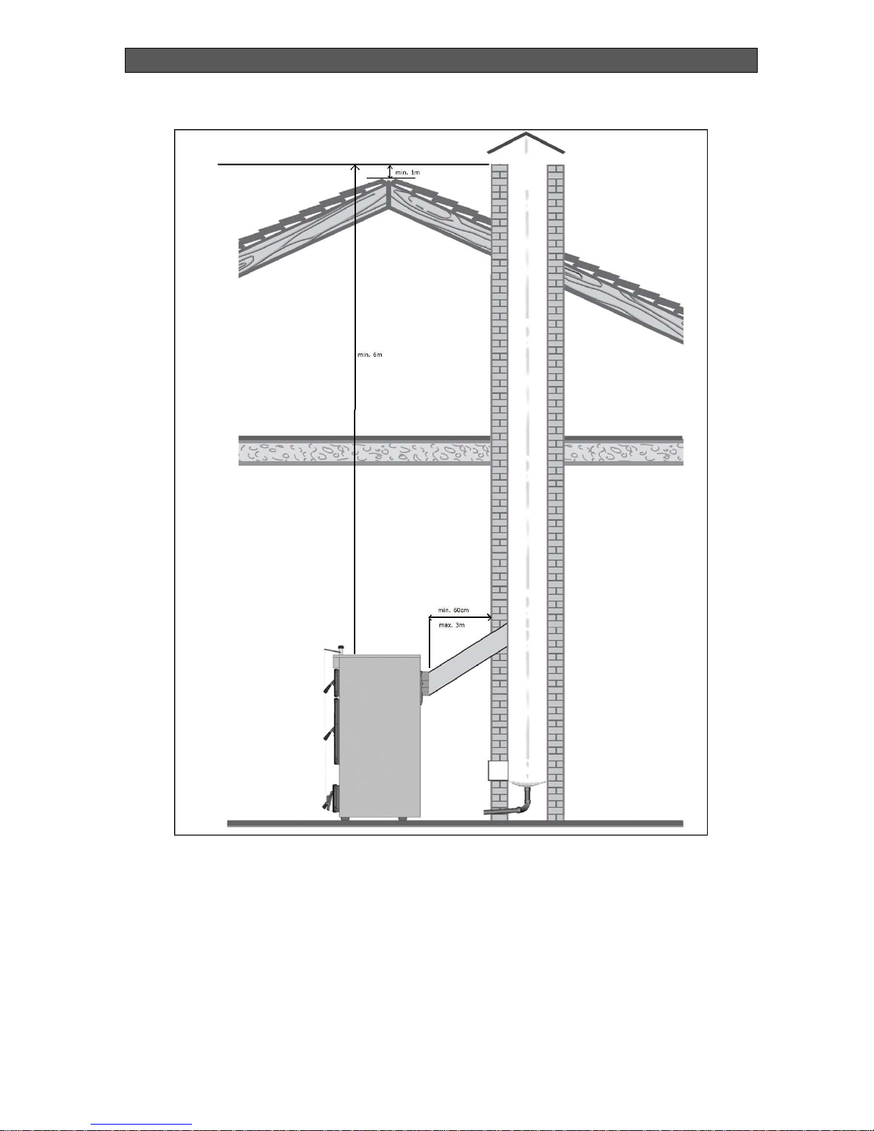
Figure 17 presents the correct connecting of the boiler flue pipeline to the chimney, by
additional pipe connection. Please observe the following rules when installing the flue
pipelines to the chimney:
Install the flue pipelines (pipe connection) to the chimney by checking the cleaning
manhole.
Fix the pipeline to the boiler flue outlet.
Install the flue gasses pipe to the chimney, by using the shortest track, without using
excessive number of bends. Avoid undesirable coupling sections, especially with 90 °
connection angle.
Fix the pipelines reliably by using enough number of supports (especially for long flue
pipelines).
The flue pipeline (pipe connection) must be installed carefully in order not to loosen,
because it is fixed only to the chimney inlet.
Use parts and components for connecting the boiler flue outlet to the chimney that are
made only from inflammable materials.
Page 37
INSTALLATION, OPERATION AND MAINTENANCE MANUAL
BiSolid Comfort OM-BSCV00/08/2012/EN
37
Figure 17. Flue pipeline installation.
7.11. CHIMNEYS AND ADVICES FOR CONNECTING TO
CHIMNEYS
It is enough to have a drawing for connecting the boiler flue outlet to the chimney, as main
condition for the boiler correct functioning. This requirement is essential and determines the
efficiency and correct operation of the system. Therefore the following features should be
noticed when connecting the boiler flue outlet to the chimney:
Page 38

INSTALLATION, OPERATION AND MAINTENANCE MANUAL
BiSolid Comfort OM-BSCV00/08/2012/EN
38
Have in mind that the boiler must be connected to the chimney system (to flue gasses)
in accordance to the local legal conditions.
When connecting the boiler to the chimney it is necessary to ask professional installer
for consultation and installation, because all activities must conform to the regulations
for installation and the manufacturer instructions.
The boiler can be correctly connected to the chimney by using a chimney system
project and technical specification.
The chimney system design sizing (flue gas pipelines system) must be based on the
flue gasses mass flow rate, at maximum heating output of the boiler.
The effective height of flue gas chimney is determined by the coupling point of the
boiler flue outlet to the chimney.
Make sure that the chimney system sizing and the flue connection to the chimney is
performed by qualified specialist.
If the boiler is not connected properly to the chimney, the product warranty will be
considered as invalid.
The presented dimensions in Figure 18 are only tentative. The operation scheme depends on
the diameter, height, chimney wall roughness and temperature difference between the
combustion products and the outside air temperature. We recommend the usage of chimney
with integrated metal insert.
Usually for more accurate calculations, performed by heating specialist or installer of the
chimney system, the below formula is used for determining the chimney cross-section area.
F - Chimney cross-section area, cm2.
a – Coefficient (а = 0.041 for wood logs).
QN – Boiler heating outlet, kCal/h.
H – Chimney height, m
Page 39

INSTALLATION, OPERATION AND MAINTENANCE MANUAL
BiSolid Comfort OM-BSCV00/08/2012/EN
39
8. TROUBLESHOOTING
Failure Reason Solution
The fuel quality is low due to
high water content.
Try using fuel with higher
caloricity and lower water
content.
Operation instructions are not
observed.
Check the chimney draught,
chimney flap position, inlet
water temperature.
Tar deposits over the heatexchanger surface.
Clean the heat-exchanger
with a brush, supplied by the
manufacturer or with similar.
The boiler does not
generate hot water
Caused by improper burner
operation.
See the burner BiSolid GP
operation manual.
The used fuel is with high
water content.
Use proper quality fuel. Excesive boiler
condensation and black
liquid formation
Low outlet water
temperature.
Try to operate the boiler with
flue gas temperature of
160°C over the ambient
temperature.
The boiler lower door is not
or is incorrectly sealed while
closing.
Check the lower door sealing
or replace it with new.
The boiler outlet water
temperature can not be
adjusted
The water temperature
gauge does not function.
Check the temperature
gauge working order.
The circulations pump does
not function or the water
circulation is blocked (for
example closed valve).
Check the circulation system
working order, especially the
water pump.
The boiler generates hot
water but the radiators are
cold.
Presence of air in the heating
system.
Bleed (air-free) the heating
installation.
In all other cases removing of eventual failures must be performed by the manufacturer or
authorized servicing company.
Page 40

INSTALLATION, OPERATION AND MAINTENANCE MANUAL
BiSolid Comfort OM-BSCV00/08/2012/EN
40
Supplier:
Address:
City.
Str.
Tel.:
Fax.:
http://
Reserved rights for technical changes!
 Loading...