

BiSolid Automat, Automat 25, Automat 35, Automat 45, Automat 60 Installation, Operation And Maintenance Manual
Page 1
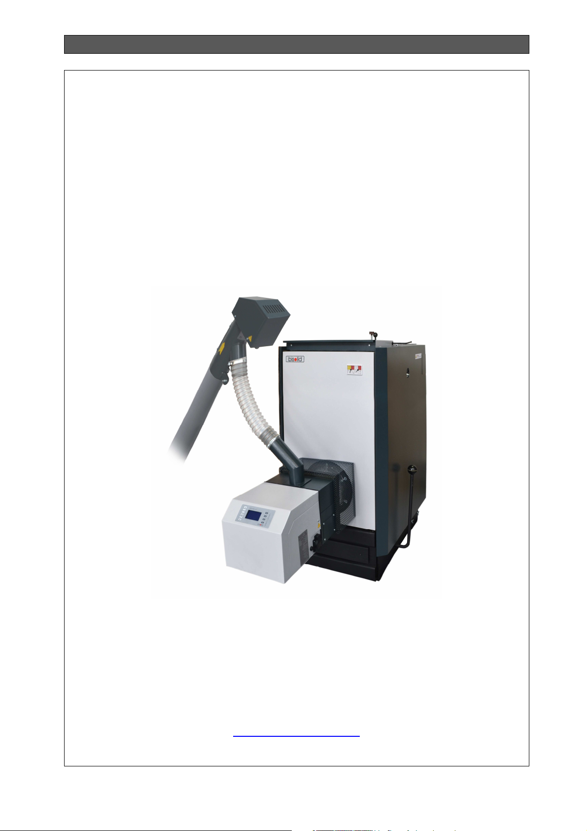
INSTALLATION, OPERATION AND MAINTENANCE MANUAL
MANUAL
FOR INSTALLATION, OPERATION AND MAINTENANCE OF
SOLID FUEL HOT WATER BOILER SERIES
BISOLID AUTOMAT
http://www.bisolid.bg
Bisolid Automat 22-Feb-18 OM-BAV05/02/2018/EN
Page 2

INSTALLATION, OPERATION AND MAINTENANCE MANUAL
Bisolid Automat OM-BAV05/02/2018/EN
2
Page 3

INSTALLATION, OPERATION AND MAINTENANCE MANUAL
CONTENT page.
1. SYSTEM OPERATION IMPORTANT INFORMATION 5
1.1. SAFETY INSTRUCTIONS 5
2. GENERAL BOILER REQUIREMENTS 7
2.1. ENSURING SAFETY OF PERSONS AND EQUIPMENT 8
2.2. DESIGNATION OF THE BOILER 8
2.3. FUEL 9
2.4. DESCRIPTION OF THE BOILER 11
2.5. CONSTRUCTION AND OVERALL DIMENSIONS OF THE BOILER 12
2.6. BOILER SECTIONAL VIEW 13
2.7. BOILER TECHNICAL DATA 14
3. DESCRIPTION OF THE TUBE PELLET BURNER WITH ROTARY CLEANING BISOLID GP XX R
TSC 26
3.1. TUBE PELLET BURNER TECHNICAL DATA 31
4. OPERATION INSTRUCTIONS 32
4.1. OPERATION OF BOILER BISOLD AUTOMAT 32
4.2. SAFETY OPERATION OF THE BOILER 32
5. BOILER BISOLID AUTOMAT COMMISSIONING 34
5.1. BOILER INSPECTION BEFORE COMMISSIONING 34
5.2. EXEMPLARY PRINCIPAL HYDRAULIC SCHEME 34
5.3. FILLING AND DRAINING THE HEATING SYSTEM 35
5.4. CONDENSATION AND TARS 35
5.5. BOILER MAINTENANCE 36
5.6. BOILER CLEANING AND MAINTENANCE 37
5.7. TUBE PELLET BURNER CLEANING 38
5.8. TUBE PELLET BURNER MAINTENANCE 38
5.9. PELLET BURNER SERVICING 40
5.10. BOILER REPAIR 41
5.11. WARRANTY AND WARRANTY TERMS AND CONDITIONS 41
5.12. BOILER ACCESSORIES UPON DELIVERY 41
5.13. ACTIONS AFTER COMPLETION OF THE BOILER LIFE-CYCLE 42
6. BOILER OPERATION AND CONTROL USING PREFERRED FUEL (WOOD PELLETS) 43
6.1. PURPOSE OF THE TUBE PELLET BURNER 43
6.2. PURPOSE OF THE PELLET BURNER CONTROLLER 43
6.3. OPERATION OF THE PELLET BURNER CONTROLLER 44
6.4. STARTING THE PELLET BURNER 44
6.5. STOPPING THE PELLET BURNER 44
6.6. BURNER GSM CONTROL MODULE (OFFERED AS AN OPTION) 45
6.7. METHODS FOR FORMING THE DESIRED TEMPERATURE 45
6.7.1. MANUAL DETERMINATION OF THE HEATING WATER ASSIGNMENT (ТB SET) 45
6.7.2. DETERMINATION OF THE HEATING WATER ASSIGNMENT BY ROOM THERMOREGULATOR 45
6.8. TEMPERATURE RESTRICTIONS AND PROTECTIONS 46
6.9. PELLET BURNER FRONT PANEL 46
6.10. OPERATION (FUNCTIONING) OF THE PELLET BURNER 47
6.10.1. USER`S SETTINGS 48
6.10.2. WEEKLY TIMER 48
6.10.3. ALARM MESSAGES 49
6.11. SERVICE SETTINGS 50
6.11.1. IGNITION SETTINGS 50
6.11.2. BURN MODE SETTINGS 51
6.11.3 STOP MODE SETTINGS 51
6.11.4. COMMON SETTINGS 52
6.12. SMS COMMANDS 52
6.13. PELLET BURNER ELECTRICAL CONNECTIONS 53
7. BOILER OPERATION AND CONTROL WHEN OPERATED WITH OTHER SUITABLE FUEL 54
7.1. BOILER FUEL LOADING AND IGNITION 54
7.2. OTHER SUITABLE FUEL SETTINGS 55
7.3. BOILER SWITCH OFF 56
7.3.1. STOPPING THE BOILER FOR A LONG PERIOD OF TIME 56
Bisolid Automat OM-BAV05/02/2018/EN
3
Page 4

INSTALLATION, OPERATION AND MAINTENANCE MANUAL
8. WIRING DIAGRAME OF THE BOILER WITH THE PELLET BURNER 57
8.1. PALLET BURNER CONNECTOR’S PANEL 58
9. BOILER INSTALLATION INSTRUCTIONS 60
9.1. BOILER INSTALLATION - GENERAL INFORMATION 60
9.2. CHOOSING APPROPRIATE BOILER MODEL 60
9.3. POSITIONING IN THE BOILER ROOM 60
9.4. WATER SUPPLY REQUIREMENTS 61
9.5. CONNETING THE BOILER TO THE HEATING SYSTEM 62
9.6. BOILER CONNECTION TO THE SMOKE EXTRACTOR 65
9.7. BOILER CONNECTION TO THE CHIMNEY 66
9.8. TRANSPORTATION AND STORAGE 69
10. TROUBLESHOOTING 71
10.1. BOILER TROUBLESHOOTING 71
10.2. PELLET BURNER TROUBLESHOOTING 72
Bisolid Automat OM-BAV05/02/2018/EN
4
Page 5

INSTALLATION, OPERATION AND MAINTENANCE MANUAL
1. SYSTEM OPERATION IMPORTANT INFORMATION
Dear hot water boiler series Bisolid Automat owners,
We would like to congratulate you on your new ecologic boiler system. By purchasing this
quality product from the manufacturer, you have chosen a system that ensures high level of
comfort and optimized fuel consumption using an environmentally friendly way of saving
resources. Your boiler is manufactured under strict ISO 9001 standards.
On the following pages we have provided specific information and important advice about the
system operation, its functions and way of maintenance. Please, pay special attention to this
manual. Good knowledge of this document content will give you the pleasure of long-term and
trouble-free operation of the system.
1.1. SAFETY INSTRUCTIONS
Hot water boiler series Bisolid Automat and its accessories correspond to all applicable safety
regulations. The hot water boiler and all its accessories operate using alternating current of
230 VAC. Improper electrical installation or its repair may impose risk of life-threatening
electric shock on the users. Installation works should be performed only by appropriately
qualified technicians.
This manual is intended for authorized service specialists only. It is important to know that:
Works on the heating installation should be performed only by installers who have
acquired such rights by the competent authorities.
Works on the electrical installation should be performed by qualified electricians only.
Initial start-up, including inspection of the installation performed, boiler settings and
commissioning should be performed by an authorized representative of the
manufacturer.
Legal provisions
While operating with the equipment please observe:
Safety legal provisions.
Legal provisions for environmental protection.
Provisions for professional installation.
Applicable provisions of the European community.
Safety Instructions
Please observe these safety instructions in order to prevent risks and harm to
persons, property damage and damage to the environment.
Safety instructions explanation.
Please, pay attention to the following symbols in this manual:
Danger
This symbol warns for risk of harm to persons.
Warning
This symbol warns for risks of damage to property and damage to the
environment.
Bisolid Automat OM-BAV05/02/2018/EN
5
Page 6

INSTALLATION, OPERATION AND MAINTENANCE MANUAL
Information
Data marked with this symbol contain additional information.
Works or activities for setting the appliance in proper technical working order
Repairs of technical safety related built-in components may compromise
safety operation of the installation. Damaged built-in components should be
replaced with genuine parts only, provided by the manufacturer.
After careful reading of the installation and operation manual, you will acquire
all necessary information regarding the design, control and safety operation of
the system. After unpacking the boiler, check the integrity and completeness of
the delivered equipment. Check whether the boiler size corresponds to the
intended purpose of use.
Upon detection of any damage, the boiler should be decommissioned and a specialized
company should provide troubleshooting of the boiler. For proper functioning, safety and
continuous operation of the equipment, systematic checkups and preventive maintenance
should be carried out at least once a year. This will guarantee your investment.
Repairs should be performed only with genuine spare parts. In the case of
faults caused by unqualified installation, failure to comply with the prescriptions
or the operation manual, the manufacturer shall not bear any responsibility and
shall not provide any warranty.
Bisolid Automat OM-BAV05/02/2018/EN
6
Page 7

INSTALLATION, OPERATION AND MAINTENANCE MANUAL
2. GENERAL BOILER REQUIREMENTS
The boiler and all related equipment should be installed and used in accordance with the
designed installation, all applicable legal provisions and technical standards, and the
manufacturer's instructions. The boiler shall be used only for its intended purpose.
The boiler shall be installed only for the purpose it has been designed for. If the boiler is
delivered to the user and installed by the same person, the latter should provide the user with
the entire accompanying documentation of the boiler (in particular, the user`s manual). Keep
the genuine packaging of the boiler until its commissioning, in case the boiler should be
transported again.
After installation, the boiler should be commissioned by a service provider, authorized by the
manufacturer.
The boiler complies with the European Union applicable provisions. If the boiler is to be used
in countries outside the EU, all deviations from local laws and legal provisions should be
identified and corrected.
In case of defect, contact a service provider authorized by the manufacturer. Any incompetent
intervention might damage the boiler (and possibly the accompanying equipment).
During initial commissioning of the boiler, the service technician should acquaint the user with
the boiler main parts, different boiler systems and how to control the boiler. The technician
should acquaint the user with the safety equipment and elements of the boiler, their signals
and explain the appropriate reaction of the user. If the boiler is delivered to the user and
installed by the same person, the latter should ensure that genuine packaging is available in
case the boiler should be transported again.
Check the delivered boiler accessories.
Check whether the delivered model and type of the boiler correspondent to the use
requirements.
When you are not sure how to control the boiler read carefully the relevant instructions in this
operation and installation manual and proceed accordingly.
Never take off or damage the marks and signs on the boiler. Keep the genuine packaging,
until commissioning of the boiler, in case the boiler should be transported again.
Always use, only genuine parts for repairs. It is forbidden to make any changes on the internal
installation of the boiler or to change anything in anyway.
At the end of its lifetime, the boiler should be packed and together with its parts disposed of in
a manner that prevents pollution of the environment.
The manufacturer is not liable for damages caused by non-compliance with:
Terms and conditions provided for in this operation and installation manual.
Applicable regulations and standards.
Installation and operation procedures.
Warranty card terms and conditions.
The possible situations that can be possible to occur, and key precautions to be taken:
Bisolid Automat OM-BAV05/02/2018/EN
7
Page 8

INSTALLATION, OPERATION AND MAINTENANCE MANUAL
Switch off the boiler, if there are any (even temporary) flammable or explosive vapors
in the room, from which the combustion air is supplied to the boiler (for example, from
paint while painting, from laying and spraying molten substances, from gas leakage
etc.).
If it is necessary to drain the water from the boiler or from the entire system, the water
should not be dangerously hot.
If there is any leakage from the boiler`s heat-exchanger or if the heat-exchanger is
clogged, do not attempt to start the boiler, until normal operation conditions are
restored.
2.1. ENSURING SAFETY OF PERSONS AND EQUIPMENT
The boiler and all its parts are in compliance with the safety requirements of the relevant EU
norms.
In order to install and operate the boiler, in accordance with its intended actual use
(hereinafter referred to only as use), it is necessary to also observe additional requirements,
the most important of which (i.e. those should not be omitted) are present in the relevant
regulatory documents. In addition to the above mentioned documents, when using the boiler, it
is necessary, to act in accordance with this installation and operation manual and the
accompanying boiler documentation supplied by the manufacturer.
Any intervention on the boiler operation by children and persons under the influence of
narcotic substances, psychiatric abnormalities and other, should be prevented.
When installing a Bisolid Automat boiler on the heating system always observe
the requirements indicated in section 9.5 for the installation of the boiler
equipment excess heat release.
When operating the boiler Bisolid Automat, always a heating circuit has to be
included in which the water is circulated. If the heating radiators are equipped
with thermostatic valves (or other control components), which close the
circulations water flow. As a result of this process it is possible that the
generated heat energy, from the fuel final combustion, can’t be adopted by the
heating system (can’t be unloaded) and to lead to overheating of the appliance.
Therefore in case the boiler Bisolid Automat is operated in heating systems with
radiator regulation valves, it is necessary not to completely close the radiator
valves, but to adjust them to minimum value. Also one of the radiators should
not be equipped with regulation valve, in order to ensure adoption of the heat
energy generated during the process of final combustion.
2.2. DESIGNATION OF THE BOILER
The steel made hot water boiler series Bisolid Automat is a heating source, suitable for
heating dwellings, single-family houses, production workshops and other similar sites. The
heating system may be implemented with an open or closed expansion tank, with independent
or forced circulation of the heating water, with maximum overpressure of 2.0 bar.
The innovative automatic switching of the boiler between preferred fuel (wooden pellets) and
other suitable fuel (firewood or wood chips) provides continuous comfort at a reasonable price.
The pellet burner with self-cleaning automatically is switching off after adding and unburning of
Bisolid Automat OM-BAV05/02/2018/EN
8
Page 9

INSTALLATION, OPERATION AND MAINTENANCE MANUAL
other sitable fuel, and in its burning, the burner automatically switches on and continues to
maintain the set temperature with the preferred fuel.
The optimum functionality of the equipment is determined both by the professionally designed
heating installation and by the precise maintenance of the system.
Boilers series Bisolid Automat are offered like product’s modiifications of boilers
Bisolid Automat 25, Bisolid Automat 35, Bisolid Automat 45 and
Bisolid Automat 60 standart equipped by tube pellet burners with rotary self-
cleaning series Bisolid GP xx R tsc.
The main advantages of heating boilers series Bisolid Automat are:
Easy and fast switching between the preferred and other suitable fuel. Automatic
ignition and unburning of firewood and wood chips.
Ability to burn firewood and wood chips with high moisture.
Intuitive self-adjastment of the burner operation according to the moisture of other
suitable fuel for better combustion.
Fully automatic operation of the pellet burner in combustion of the preferred fuel -
ignition, control the flame, blowing the combustion chamber.
Convenient and easy to use graphical LCD display with English menu, showing the
current state of the parameters of the combustion process.
High efficiency of the facility with minimum fuel consumption, thanks to the automatic
settings of the required air and fuel, according to the user's chosen temperature.
Automatic modulation of the combustion process, reducing the number of stops and
the ignition respectively consumption of fuel and electricity.
Control circulation pump according to the coolant temperature.
Quiet operation and low power consumption of electric energy.
High level of safety - protection against back fire, freezing and blocking of the coolant
circulation pump.
Control of flue gas fan.
Operation with room thermostat and weekly programmer at pellets mode.
Removable cast iron grate for easy cleaning of ash in the combustion chamber of the
boiler.
Convenient and easy to clean ashtray.
Control of the combustion process at room temperature;
Ability to control and outside temperature.
Delayed start.
Control the burner via GSM module (optional) by sending SMS commands - ability to
stop, start and view its current state.
2.3. FUEL
The boilers series Bisolid Automat are able to utilize wood pellets as preferred fuel according
to standard EN ISO 17225-2:2014, classes A1, A2 and B with the following characteristics
(Table 1.):
Bisolid Automat OM-BAV05/02/2018/EN
9
Page 10

INSTALLATION, OPERATION AND MAINTENANCE MANUAL
≥
<
≥
<
≥
<
≥
<
≥
<
Table 1. Standard for wood pellets EN ISO 17225-2:2014
Parameter Dimension Class A1 Class A2 Class B
Length (L) mm 3,15 ≤ L≤ 40 3,15 ≤ L≤ 40 3,15 ≤ L≤ 40
Diameter (D) mm 6±1
8±1
Moisture (М) % < 10 < 10 < 10
Ash (A), dry matter % < 0,7 < 1,2 < 2,0
Buck density (BD) kg/m3 > 600 > 600 > 600
Mechanical durability (DU) % > 97.5 > 97.5 > 96.5
Net caloricity (Q) MJ/kg
kWh/kg
Chlorine Cl % < 0,02 < 0,02 < 0,03
Nitrogen (N) % < 0,3 < 0,5 < 1,0
Sulphur (S) % < 0,04 < 0,05 < 0,05
Arsenic (As) mg/kg < 1 < 1 < 1
Cadmium (Cd) mg/kg < 0.5 < 0.5 < 0.5
Chromium (Cr) mg/kg < 10 < 10 < 10
Copper (Cu) mg/kg < 10 < 10 < 10
Lead (Pb) mg/kg < 10 < 10 < 10
Mercury (Hg) mg/kg < 0.1 < 0.1 < 0.1
Nickel (Ni) mg/kg < 10 < 10 < 10
Zinc (Zn) mg/kg < 100 < 100 < 100
The boilers series Bisolid Automat can burn as preferred fuel wood pellets category A, AB, B,
BC and C according to the classification of wood pellets developed by the manufacturer
methodology (see Table 2).
Table 2. Wood pellets classification depending on the physical properties according to a
methodology developed and applied by the manufacturer
Pellets Category AD DU
A
AB
B
BC
C
CD
D
DE
E
EF
Where:
Ad – ash content on dry matter, %.
DU – mechanical durability, %.
d
A
d
A
A
A
d
A
d
A
> 16,5
> 4.6
%6.0≤
%6.0≤
d
d
A
A
A
A
%0.16.0 ≤<
%0.16.0 ≤<
d
d
d
d
%0.2%0.1 ≤<
%0.2%0.1 ≤<
%0.3%0.2 ≤<
%0.3%0.2 ≤<
%0.3>
%0.3>
DU
DU
DU
DU
DU
DU
DU
DU
DU
DU
6±1
8±1
> 16,5
> 4.6
6±1
8±1
> 16,5
> 4.6
%0.97
%0.97
%0.97
%0.97
%0.97
%0.97
%0.97
%0.97
%0.97
%0.97
Bisolid Automat OM-BAV05/02/2018/EN
10
Page 11
INSTALLATION, OPERATION AND MAINTENANCE MANUAL
Wood pellets must be stored in dry premises, so they can be transported without problems
and also in order to achieve trouble-free operation with optimum combustion and maximum
efficiency. The preferred fuel (wood pallets) should be stored in dry premises, so that it can be
transported without problems thus enabling trouble-free operation with optimum combustion
and maximum efficiency.
Boilers series Bisolid Automat can utilize firewood as other suitable fuel with maximum
humidity 25%, i.e. in the form of chopped firewood logs with diameter up to100 mm and length
400 mm, split firewood with bark or without bark. The manufacturer recommends that the fuel
be applied transversely in the fuel hopper, so as to achieve gradual combustion and fuel
layering.
Boilers series Bisolid Automat can also utilize as other suitable fuel wood chips as well with
maximum moisture of 40%.
When using firewood or wood chips with irregular or non-compliant form, additional control
should be exercised on the boiler by the service personnel.
Supply of fresh air to the combustion chamber of the boiler through the tube
pellet burner fan, which is automatically activated, allowing for burning of fire
wood and wood chips with higher moisture.
The mounted to the heating boiler Bisolid Automat pellet burner with rotary selfcleaning Bisolid GP xx R tsc is designed for burning of the approved by the
boiler manufacturer solid fuels ONLY!
Hot water boilers series Bisolid Automat are not designed to burn coal.
2.4. DESCRIPTION OF THE BOILER
The boiler is a welded construction of steel sheet panels and pipes. The inside space is
separated by water baffle into a fuel hopper, combustion chamber and heat-exchanger,
through which the flue gases are discharged to the chimney neck. A movable two-component
grate is located under the combustion chamber and the fuel hopper, which is run laterally
using a lever.
The combustion air is supplied by a fan, located in the pellet burner of the boiler, controlled by
an electronic device.
Heating water inlet and outlet are secured by nozzles G1
backside of the boiler along its axis. The exhaust gases (flue gases) discharge valve is
controlled from the top of the boiler. The exhaust gases discharge flap (flue gases evacuation
flap) serves to evacuate the flue gases during loading the fuel hopper of the boiler. The flap
opens during loading other suitable fuel (firewood and wood chips) into the fuel hopper of the
boiler and closes immediately thereafter.
Not opening the flue gases flap may result in a smoke in the boiler fuel hopper during loading
other suitable fuel.
The flue gas discharge flap (flue gases evacuation flap) should be opened only
during loading the boiler hopper with other suitable fuel. The flap should be
closed immediately after closing the door of the fuel hopper.
1/2"
. The flue pipe is located on the
Bisolid Automat OM-BAV05/02/2018/EN
11
Page 12
INSTALLATION, OPERATION AND MAINTENANCE MANUAL
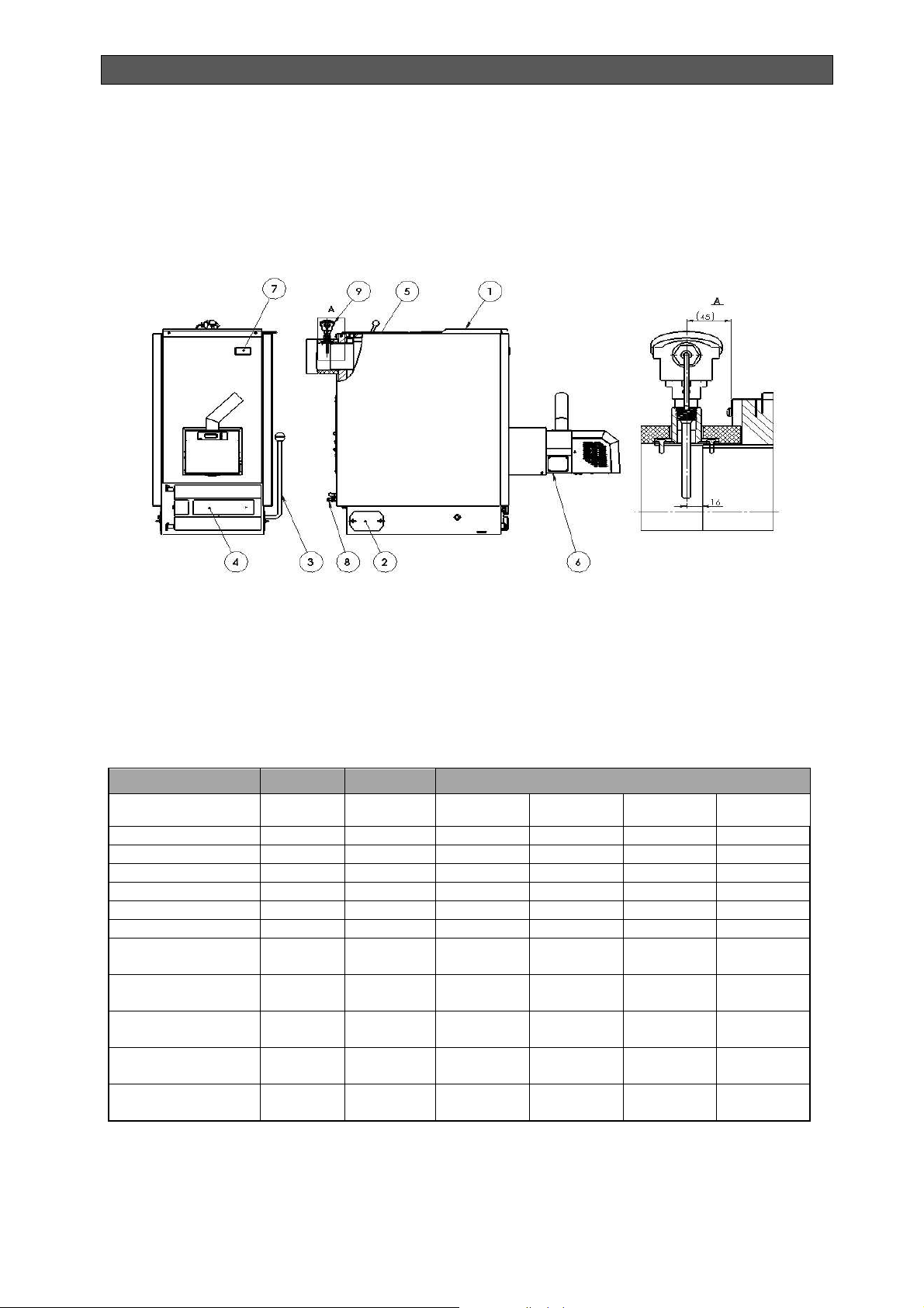
2.5. CONSTRUCTION AND OVERALL DIMENSIONS OF THE BOILER
The main elements of the construction of hot water boiler series Bisolid Automat are presented
in Figure 1. The overall dimensions of hot water boilers Bisolid Automat are presented in Table
3 and Figure 2.
Figure 1. Main elements of the construction of Bisolid Automat boiler
1. Other suitable fuel feeding door
2. Soot door
3. Grate lever
4. Ash cleaning door
6. Tube pellet burner
7. Thermo-manometer
8. Drainage valve
9. Exhaust (flue) gas sensor
5. Heat-exchanger cover with firing flap
Table 3. Overall and mounting dimensions of Bisolid Automat boiler
Parameter Indication Dimension
Nominal heat ouput
Boiler height А mm 847 1048 1148 1150
Boiler overall height
Boiler length В mm 896 896 896 1001
Boiler overall length В1 mm 1443 1443 1443 1602
Boiler width С mm 595 595 595 745
Boiler overall width С1 mm 657 657 657 805
Height of the hot
water flange - outlet
Flue pipe axis
height
Height of the hot
water flange - inlet
Inlet and outlet
nozzle
Chimney diameter
(outer)
- -
А1 mm 894 1094 1194 1249
D mm 763 963 1058 1058
E mm 695 895 995 995
F mm 195 195 195 215
- G 1 1/2" 1 1/2" 1 1/2" 1 1/2"
∅
mm 150 150 150 150
Bisolid
Automat 25
Automat 35
Bisolid
Value
Automat 45
Bisolid
Bisolid
Automat 60
Bisolid Automat OM-BAV05/02/2018/EN
12
Page 13
INSTALLATION, OPERATION AND MAINTENANCE MANUAL
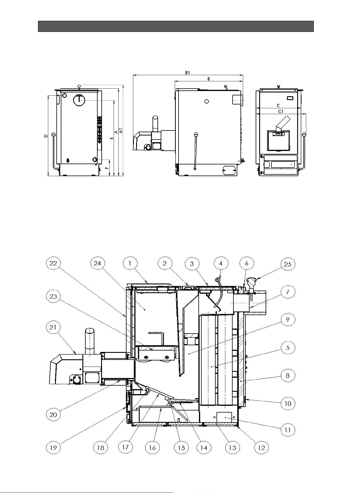
Figure 2. Overall and mounting dimensions of Bisolid Automat boiler
2.6. BOILER SECTIONAL VIEW
The main sectional view of Bisolid Automat boiler is presented in Figure 3.
Figure 3. Main sectional view of Bisolid Automat boiler
Bisolid Automat OM-BAV05/02/2018/EN
13
Page 14
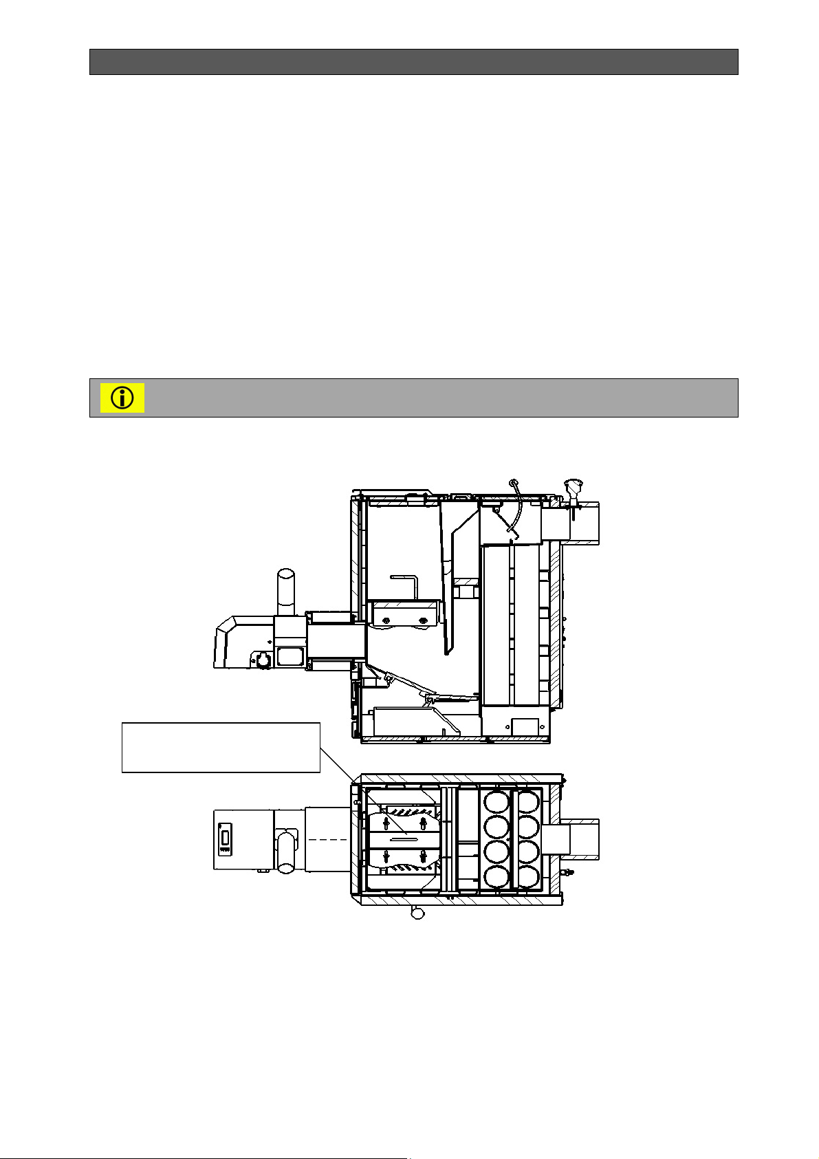
INSTALLATION, OPERATION AND MAINTENANCE MANUAL
1. Other suitable fuel feeding door
2. Middle cover
3. Rear cover with a flap
4. Flue gases flap with a handle
5. Second flue gas pass
6. Rear section
7. Chimney neck ∅ 150
8. Insulation surface
9. First flue gas pass
10. Cold water inlet
11. Cleaning cap
12. Feet bushings
13. Bottom insulation
14. Movable grate
The grate for burning other suitable fuel in the form of wood chips - position 23
of Figure 3, is offered as an option.
Figure 4. Sectional view of Bisolid Automat boiler - way of grate positioning in burning of other
suitable fuel (wood chips)
15. Lever axis for operating the grate
16. Ash tray
17. Rotating grate
18. Axis of rotation
19. Ash cleaning door
20. Burner transition
21.Tube pellet burner
22. Front cover
23. Grate for burning of other suitable fuel
(wood chips) - optional.
24. Firewood hopper
25. Exhaust (flue) gas sensor
Grate for burning of other
suitable fuel (wood chips)
2.7. BOILER TECHNICAL DATA
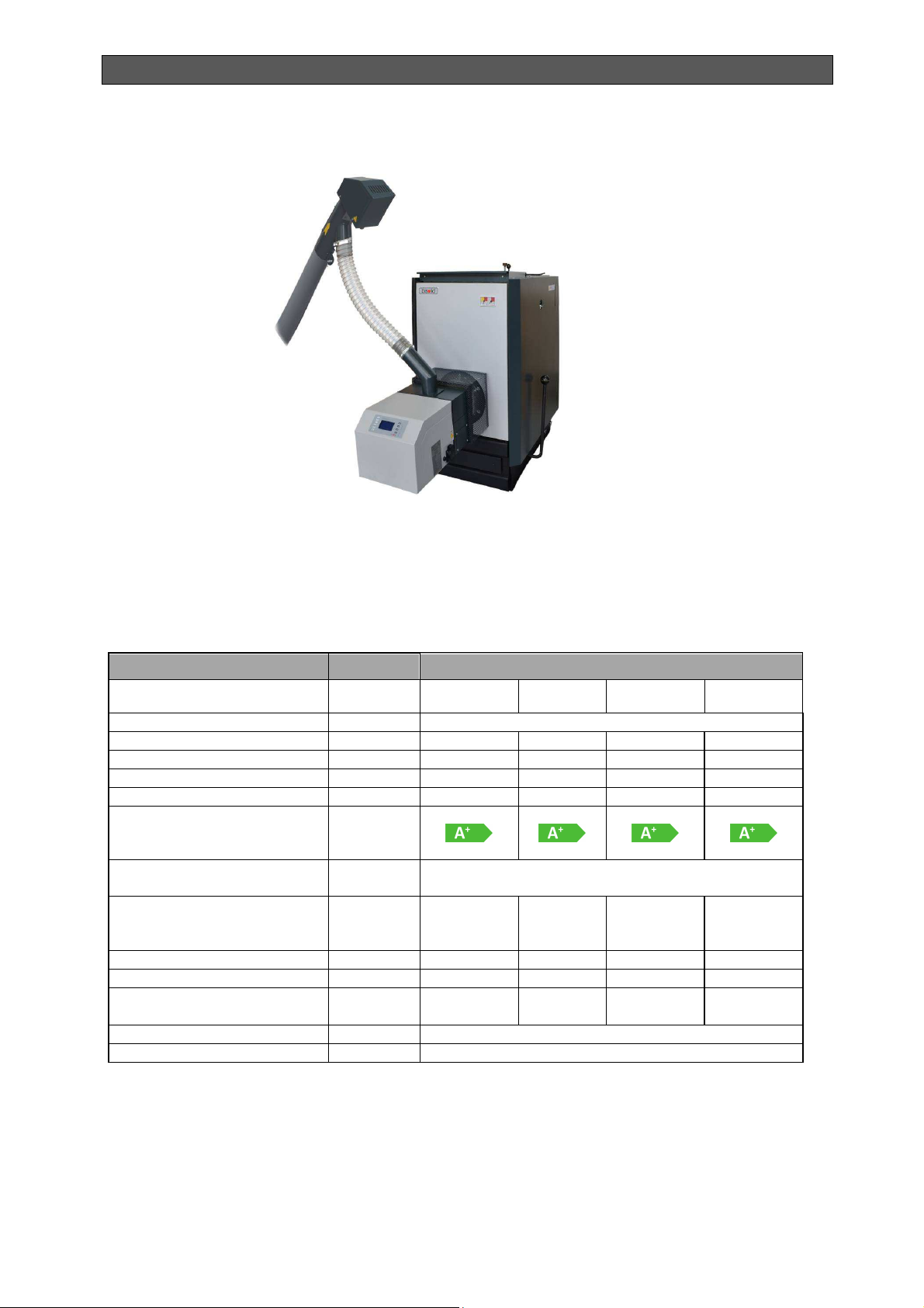
The outer view of hot water boiler series Bisolid Automat is presented in Figure 5.
Bisolid Automat OM-BAV05/02/2018/EN
14
Page 15
INSTALLATION, OPERATION AND MAINTENANCE MANUAL
Figure 5. Outer view of hot water boiler series Bisolid Automat
Technical data of hot water boiler series Bisolid Automat burning preferred fuel (wood pellets)
are presented in Tables 4.
Table 4. Hot water boiler series Bisolid Automat technical data in operation with
preferred fuel (wood pellets)
Parameter Dimension
Boiler model -
Preffered fuel - Wood pellets
Nominal heat output kW 18 26 30 40
Operating pressure bar 2.0 2.0 2.0 2.0
Operating draft Ра > 20 > 20 > 30 > 37
Efficiency % 87 90 86 80
Energy efficiency class
according to regulation (ЕU)
2015/1187
Boiler class according to
standard EN 303-5:2012
Flue gas temperature at rated
power
Boiler water volume l 70 100
Hopper volume l 79 105
Boiler weight including the
pellet burner
Power supply - 230VAC, 50Hz
Electrical protection - IP 20
-
-
о
С 180 170 194
kg 261 311 324
Bisolid
Automat 25
Bisolid
Automat 35
The technical parameters of hot water solid fuel boilers series Bisolid Automat according to the
delegated Regulation (EU) 2015/1187 are presented in Table 5.
Value
Automat 45
5
Bisolid
105
119
Bisolid
Automat 60
260
130
180
465
Bisolid Automat OM-BAV04/10/2017/EN 15
Page 16

INSTALLATION, OPERATION AND MAINTENANCE MANUAL
no
no
no
no
no
no
no
no
no
no
no
no
Characteristics when operating with the preferred fuel:
Table 5. Technical parameters of hot water solid fuel boilers series Bisolid Automat according
to the delegated Regulation (EU) 2015/1187.
Model identifier: Hot water solid fuel boiler Bisolid Automat 25.
Stoking mode: Automatic: it is recommended that the boiler be operated with a hot water storage
tank of a volume of at least 500 litre
Condensing boiler: no
Solid fuel cogeneration boiler: no
Combination boiler: no
Fuel
Log wood, moisture content ≤ 25 % no yes
Chipped wood, moisture content 15-35 % no
Chipped wood, moisture content > 35 % no
Compressed wood in the form of pellets yes no
Sawdust, moisture content ≤ 50 % no
Other woody biomass no
Non-woody biomass no
Bituminous coal no
Preferred
fuel (only one):
Other suitable
fuel(s):
yes
Brown coal (including briquettes) no
Coke no
Anthracite no
Blended fossil fuel briquettes no
Other fossil fuel no
Blended biomass (30-70 %) and fossil fuel briquettes no
Other blend of biomass and fossil fuel no
Seasonal space heating energy efficiency ƞs [%]: 84
Energy efficiency index EEI: А+
Bisolid Automat OM-BAV04/10/2017/EN 16
Page 17

INSTALLATION, OPERATION AND MAINTENANCE MANUAL
Auxiliary electricity consumption
Item Symbol Value Unit Item Symbol
Useful heat output Useful efficiecny
Value Unit
At rated heat
Pn (***) 18,0 kW
output
At [30 %/50%] of
Рр 9,0 kW
rated heat
output, if
applicable
For solid fuel cogeneration boilers: Electrical
efficiency
At rated heat
output
Ƞ
el,n
-
%
At rated heat
output
At [30 %/50%]
of rated heat
output, if
applicable
At rated heat
output
At [30 %/50%]
of rated heat
output, if
applicable
Of incorporated
secondary emission
abatement equipment,
if applicable
ƞn 87,0 %
ƞp 89,0 %
el
0,080 kW
max
el
0,080 kW
min
- -
PSB 0,0048 kW
Contact details
In standby
mode
Ekoterm Proekt EAD / ZMM Haskovo AD
6300, Haskovo
67 Saedinenie Blvd.
(*) Tank volume = 45 × Pr × (1 – 2,7/Pr) or 300 litres whichever is higher, with Pr indicated in kW
(**) Tank volume = 20 × Pr with Pr indicated in kW
(***) For the preferred fuel Pn equals Pr
Bisolid Automat OM-BAV04/10/2017/EN 17
Page 18

INSTALLATION, OPERATION AND MAINTENANCE MANUAL
no
no
no
no
no
no
no
no
no
no
no
no
Characteristics when operating with the preferred fuel:
Model identifier: Hot water solid fuel boiler Bisolid Automat 35.
Stoking mode: Automatic: it is recommended that the boiler be operated with a hot water storage
tank of a volume of at least 700 litre
Condensing boiler: no
Solid fuel cogeneration boiler: no
Combination boiler: no
Fuel
Log wood, moisture content ≤ 25 % no yes
Chipped wood, moisture content 15-35 % no
Chipped wood, moisture content > 35 % no
Compressed wood in the form of pellets yes no
Sawdust, moisture content ≤ 50 % no
Other woody biomass no
Non-woody biomass no
Bituminous coal no
Preferred
fuel (only one):
Other suitable
fuel(s):
yes
Brown coal (including briquettes) no
Coke no
Anthracite no
Blended fossil fuel briquettes no
Other fossil fuel no
Blended biomass (30-70 %) and fossil fuel briquettes no
Other blend of biomass and fossil fuel no
Seasonal space heating energy efficiency ƞs [%]: 86
Energy efficiency index EEI: А+
Bisolid Automat OM-BAV04/10/2017/EN 18
Page 19

INSTALLATION, OPERATION AND MAINTENANCE MANUAL
Auxiliary electricity consumption
Item Symbol Value Unit Item Symbol
Useful heat output Useful efficiecny
Value Unit
At rated heat
Pn (***) 26,0 kW
output
At [30 %/50%] of
Рр 8,0 kW
rated heat
output, if
applicable
For solid fuel cogeneration boilers: Electrical
efficiency
At rated heat
output
Ƞ
el,n
-
%
At rated heat
output
At [30 %/50%]
of rated heat
output, if
applicable
At rated heat
output
At [30 %/50%]
of rated heat
output, if
applicable
Of incorporated
secondary emission
abatement equipment,
if applicable
ƞn 90,3 %
ƞp 91,3 %
el
0,080 kW
max
el
0,080 kW
min
- -
PSB 0,0048 kW
Contact details
In standby
mode
Ekoterm Proekt EAD / ZMM Haskovo AD
6300, Haskovo
67 Saedinenie Blvd.
(*) Tank volume = 45 × Pr × (1 – 2,7/Pr) or 300 litres whichever is higher, with Pr indicated in kW
(**) Tank volume = 20 × Pr with Pr indicated in kW
(***) For the preferred fuel Pn equals Pr
Bisolid Automat OM-BAV04/10/2017/EN 19
Page 20

INSTALLATION, OPERATION AND MAINTENANCE MANUAL
no
no
no
no
no
no
no
no
no
no
no
no
Characteristics when operating with the preferred fuel:
Model identifier: Hot water solid fuel boiler Bisolid Automat 45.
Stoking mode: Automatic: it is recommended that the boiler be operated with a hot water storage
tank of a volume of at least 900 litre
Condensing boiler: no
Solid fuel cogeneration boiler: no
Combination boiler: no
Fuel
Log wood, moisture content ≤ 25 % no yes
Chipped wood, moisture content 15-35 % no
Chipped wood, moisture content > 35 % no
Compressed wood in the form of pellets yes no
Sawdust, moisture content ≤ 50 % no
Other woody biomass no
Non-woody biomass no
Bituminous coal no
Preferred
fuel (only one):
Other suitable
fuel(s):
yes
Brown coal (including briquettes) no
Coke no
Anthracite no
Blended fossil fuel briquettes no
Other fossil fuel no
Blended biomass (30-70 %) and fossil fuel briquettes no
Other blend of biomass and fossil fuel no
Seasonal space heating energy efficiency ƞs [%]: 84
Energy efficiency index EEI: А+
Bisolid Automat OM-BAV04/10/2017/EN 20
Page 21

INSTALLATION, OPERATION AND MAINTENANCE MANUAL
Auxiliary electricity consumption
Item Symbol Value Unit Item Symbol
Useful heat output Useful efficiecny
Value Unit
At rated heat
Pn (***) 30,0 kW
output
At [30 %/50%] of
Рр 9,8 kW
rated heat
output, if
applicable
For solid fuel cogeneration boilers: Electrical
efficiency
At rated heat
output
Ƞ
el,n
-
%
At rated heat
output
At [30 %/50%]
of rated heat
output, if
applicable
At rated heat
output
At [30 %/50%]
of rated heat
output, if
applicable
Of incorporated
secondary emission
abatement equipment,
if applicable
ƞn 86,0 %
ƞp 89,0 %
el
0,080 kW
max
el
0,080 kW
min
- -
PSB 0,0048 kW
Contact details
In standby
mode
Ekoterm Proekt EAD / ZMM Haskovo AD
6300, Haskovo
67 Saedinenie Blvd.
(*) Tank volume = 45 × Pr × (1 – 2,7/Pr) or 300 litres whichever is higher, with Pr indicated in kW
(**) Tank volume = 20 × Pr with Pr indicated in kW
(***) For the preferred fuel Pn equals Pr
Bisolid Automat OM-BAV04/10/2017/EN 21
Page 22

INSTALLATION, OPERATION AND MAINTENANCE MANUAL
no
no
no
no
no
no
no
no
no
no
no
no
Characteristics when operating with the preferred fuel:
Model identifier: Hot water solid fuel boiler Bisolid Automat 60.
Stoking mode: Automatic: it is recommended that the boiler be operated with a hot water storage
tank of a volume of at least 1200 litre
Condensing boiler: no
Solid fuel cogeneration boiler: no
Combination boiler: no
Fuel
Log wood, moisture content ≤ 25 % no yes
Chipped wood, moisture content 15-35 % no
Chipped wood, moisture content > 35 % no
Compressed wood in the form of pellets yes no
Sawdust, moisture content ≤ 50 % no
Other woody biomass no
Non-woody biomass no
Bituminous coal no
Preferred
fuel (only one):
Other suitable
fuel(s):
yes
Brown coal (including briquettes) no
Coke no
Anthracite no
Blended fossil fuel briquettes no
Other fossil fuel no
Blended biomass (30-70 %) and fossil fuel briquettes no
Other blend of biomass and fossil fuel no
Seasonal space heating energy efficiency ƞs [%]: 78
Energy efficiency index EEI: А+
Bisolid Automat OM-BAV04/10/2017/EN 22
Page 23

INSTALLATION, OPERATION AND MAINTENANCE MANUAL
Auxiliary electricity consumption
Item Symbol Value Unit Item Symbol
Useful heat output Useful efficiecny
Value Unit
At rated heat
Pn (***) 40,0 kW
output
At [30 %/50%] of
Рр 15,0 kW
rated heat
output, if
applicable
For solid fuel cogeneration boilers: Electrical
efficiency
At rated heat
output
Ƞ
el,n
-
%
At rated heat
output
At [30 %/50%]
of rated heat
output, if
applicable
At rated heat
output
At [30 %/50%]
of rated heat
output, if
applicable
Of incorporated
secondary emission
abatement equipment,
if applicable
ƞn 80,0 %
ƞp 83,0 %
el
0,080 kW
max
el
0,080 kW
min
- -
PSB 0,0048 kW
Contact details
In standby
mode
Ekoterm Proekt EAD / ZMM Haskovo AD
6300, Haskovo
67 Saedinenie Blvd.
(*) Tank volume = 45 × Pr × (1 – 2,7/Pr) or 300 litres whichever is higher, with Pr indicated in kW
(**) Tank volume = 20 × Pr with Pr indicated in kW
(***) For the preferred fuel Pn equals Pr
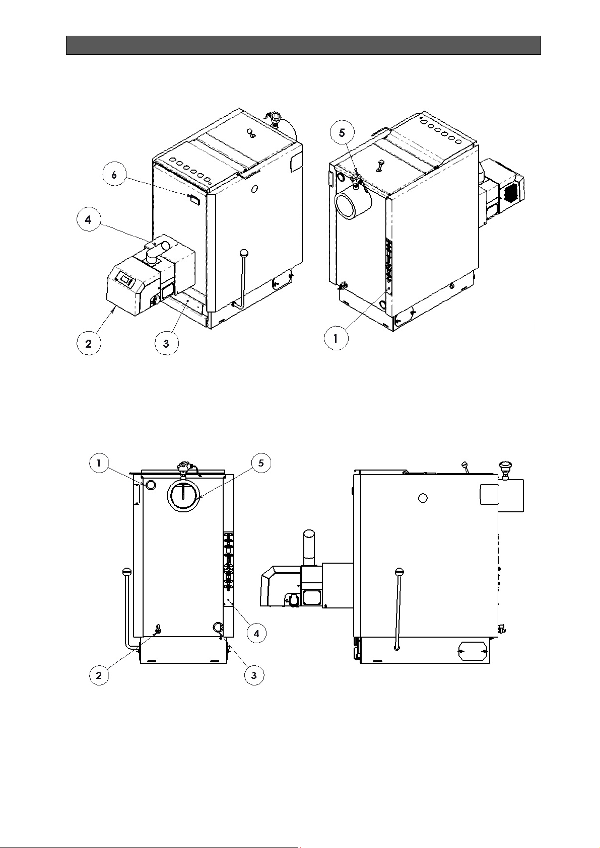
Standard equipment of hot water boilers series Bisolid Automat is shown on Figure 6 and
Figure 7.
Bisolid Automat OM-BAV04/10/2017/EN 23
Page 24
INSTALLATION, OPERATION AND MAINTENANCE MANUAL
Figure 6. Standard equipment of boilers series Bisolid Automat
1. Electrical panel
2. Tube pellet burner
3. Ash cleaning door
Figure 7. Standard equipment of boilers series Bisolid Automat
4. Safety metal grid
5. Exhaust (flue) gas sensor
6. Thermo-manometer
1. Hot water nipple
2. Drainage valve
3. Hot water nipple
Bisolid Automat OM-BAV04/10/2017/EN 24
4. Electrical panel
5. Chimney neck ø 150 mm
Page 25
INSTALLATION, OPERATION AND MAINTENANCE MANUAL
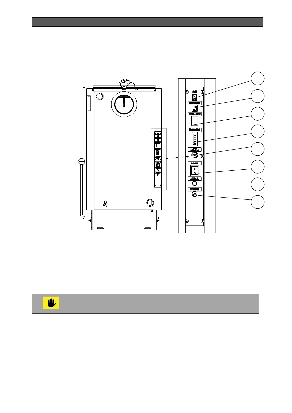
Figure 8 shows the position of the connectors on the electrical panel of hot water boiler series
Bisolid Automat.
Figure 8. Location of the connectors on the electrical panel
1
2
3
4
5
1. START switch
2. Room thermostat connector
3. Pellet burner connector - power
supply
4. Communication connector
The room thermostat may be used ONLY when operating the boiler with the
preferred fuel (wood pellets) without adding other suitable fuel!
5. Safety thermostat connector
95 ОC
6. POWER main switch
7. Fuse 10A
8. Power supply
6
7
8
Bisolid Automat OM-BAV04/10/2017/EN 25
Page 26

INSTALLATION, OPERATION AND MAINTENANCE MANUAL
3. DESCRIPTION OF THE TUBE PELLET BURNER WITH ROTARY
CLEANING BISOLID GP XX R TSC
The tube pellet burner with rotary cleaning Bisolid GP xx R tsc is a steel made construction
and is designed on the principle of feeding the wood pellets through a feed auger, then
through a flexible connection on the grate of the burner’s combustion chamber, where the
process of fuel and oxidizer (combustion air) combustion takes place.
The burner operates automatically, including: initial wood pellet loading, firing, inflammation,
combustion, controlling combustion process parameters when using preferred fuel (wood
pellets) and other suitable fuel in the form of firewood or wood chips, controlled stop when
reaching the water temperature and (or) receiving a signal from the room thermostat,
controlled power reduction in burning other suitable fuel (firewood or wood chips), final
blowing when using preferred fuel (wood pellets). In the optimization mode, at the operation
with a room thermostat, optimized modulation is carried out based on the thermal
performance of the site.
The tube pellet burner Bisolid GP xx R tsc is designed to burn wood pellets according to
standard EN ISO 17225-2:2014, classes A1, A2 and B with the relevant quality
characteristics and also pellets with categories: A, AB, B, BC and C, according to the
methodology preared and applied by the manufacturer. The fuel and air are mexed in the
burner in controlled way and it is a reason for ecological combustion and high efficiency.
The pellet burner is equipped with a display, which indicates the burner’s current parameters
and/or allows for adjustment of its operating parameters.
The main advantages of the tube pellet burner Bisolid GP xx R tsc are:
Innovative rotary combustion chamber - stable efficiency and low emissions with
minimal user intervention.
A system for mixing fuel into the combustion chamber, which increases the
cleaning of the ash, improves the combustion process and relieves servicing.
Ability to burn wood pellets with a diameter of 6-8 mm and low quality (high ash
content), which is not possible with burners with air cleaning and / or compressed
air.
Completely compatible with automatic control of a wide range of solid fuel boilers.
Suitable for installation of furnaces for bakery products.
Precision modulation of heat output.
The components of the burner are manufactured by well known and proved
European companies from Germany, United Kingdom and others.
High quality ignition element manufactured in Japan, that ensures over 37 000
ignitions.
The combustion chamber is produced by special heat resistance steel, which
ensures long service life.
Manual test of all functions.
Indication of the hot water temperature in the boiler.
Photosensor for accurately detection and monitoring of the flame intensity.
Possibility to save the current settings and to reset to factory default settings.
Automatic start after voltage drop - preserving last settings.
Password protected access levels - for the service technician and manufacturer.
Ability to operate with a room thermostat.
Possibility to control exhaust gas fan, which eliminates the problem with the
draught into the chimney and guaranties the safety operation of the product.
Bisolid Automat OM-BAV04/10/2017/EN
26
Page 27
INSTALLATION, OPERATION AND MAINTENANCE MANUAL
Special measures to increase the reliability and safety of the burner.
A flexible pipe is made of a special plastic material to connect the burner to the
auger which melts when there is a danger of back fire and do not supply fuel to
the burner - in this case, the fuel is discharged outside from the danger zone.
The standard equipment includes fuel transport auger for pellets.
Ability to start and stop using the GSM module (optional).
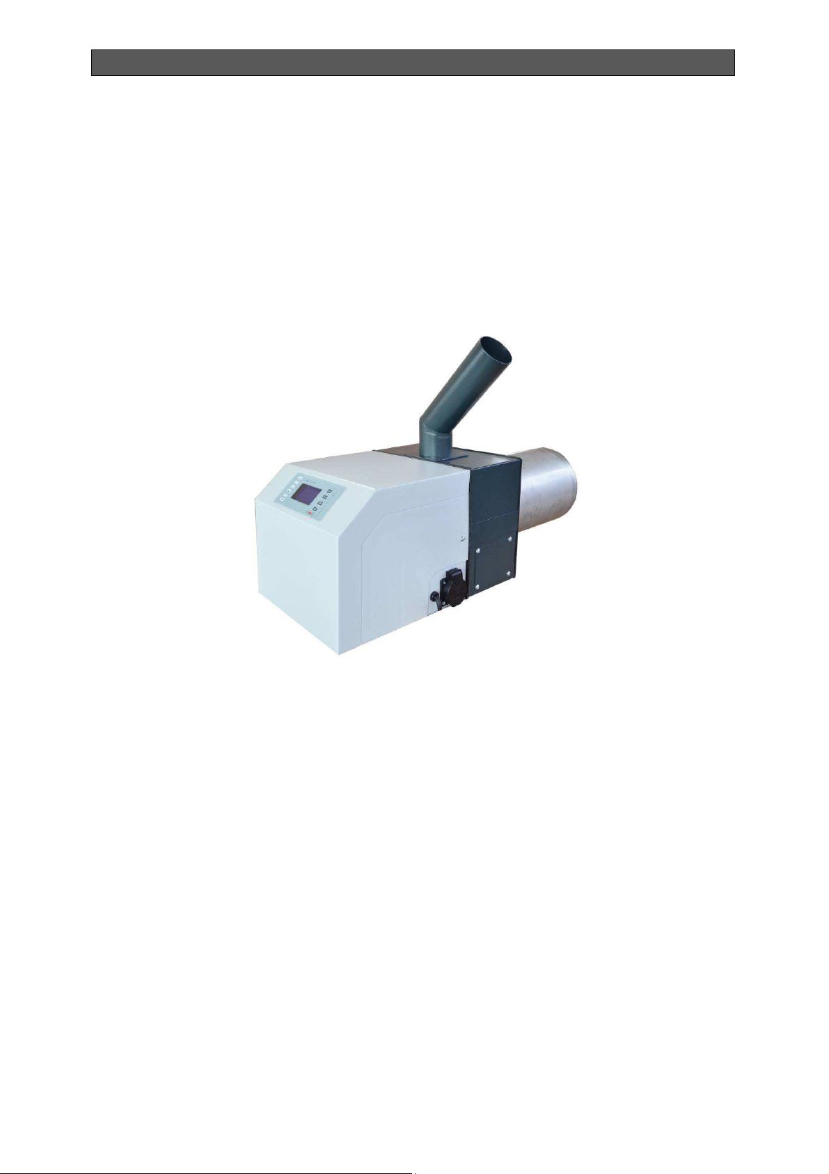
Figure 9 shows the main view of tube pellet burner with rotary self-cleaning Bisolid GP xx R
tsc.
Figure 9. Main view of tube pellet burner Bisolid GP xx R tsc
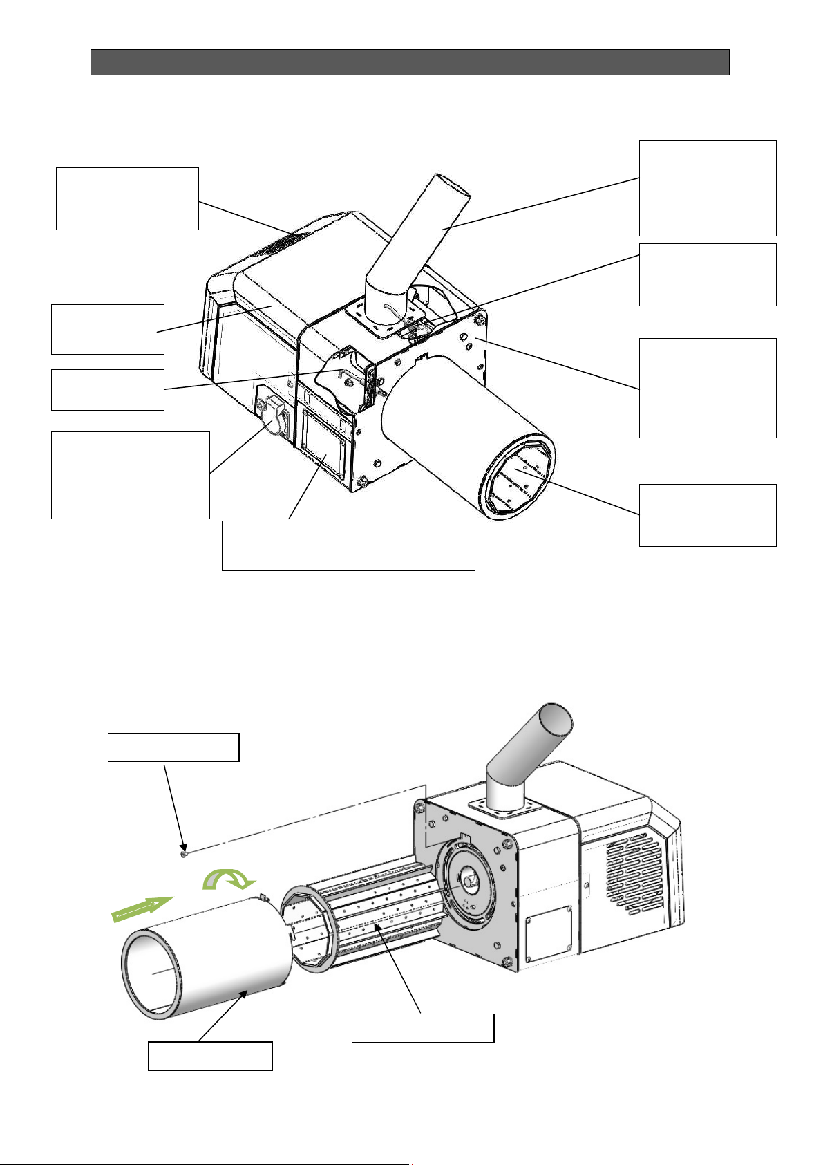
Fugure 10 presents the main module of tube pellet burner Bisolid GP xx R tsc.
Bisolid Automat OM-BAV04/10/2017/EN
27
Page 28
INSTALLATION, OPERATION AND MAINTENANCE MANUAL
fire”
protection
keyboard
)
Figure 10. Tube pellet burner Bisolid GP xx R tsc main module view
Interface panel
(display +
Burner cover
Photosensor
Contact for power
supply and control
of the transport
auger
The diagram for mounting and dismantling of the internal and external rotary tube of pellet
burner Bisolid GP xx R tsc is given in Figure 11.
Figure 11. Diagram for mounting and dismantling of the internal and external rotary tube
Inspection cover
(on both sides of the burner)
Pellets feeding
inlet pipe to
combustion
chamber
Emergency
sensor for “back
Flange for
mounting of the
main module to
the boiler
Combustion
chamber (tube)
Stopper bolt
Internal tube
External tube
Bisolid Automat OM-BAV04/10/2017/EN
28
Page 29
INSTALLATION, OPERATION AND MAINTENANCE MANUAL
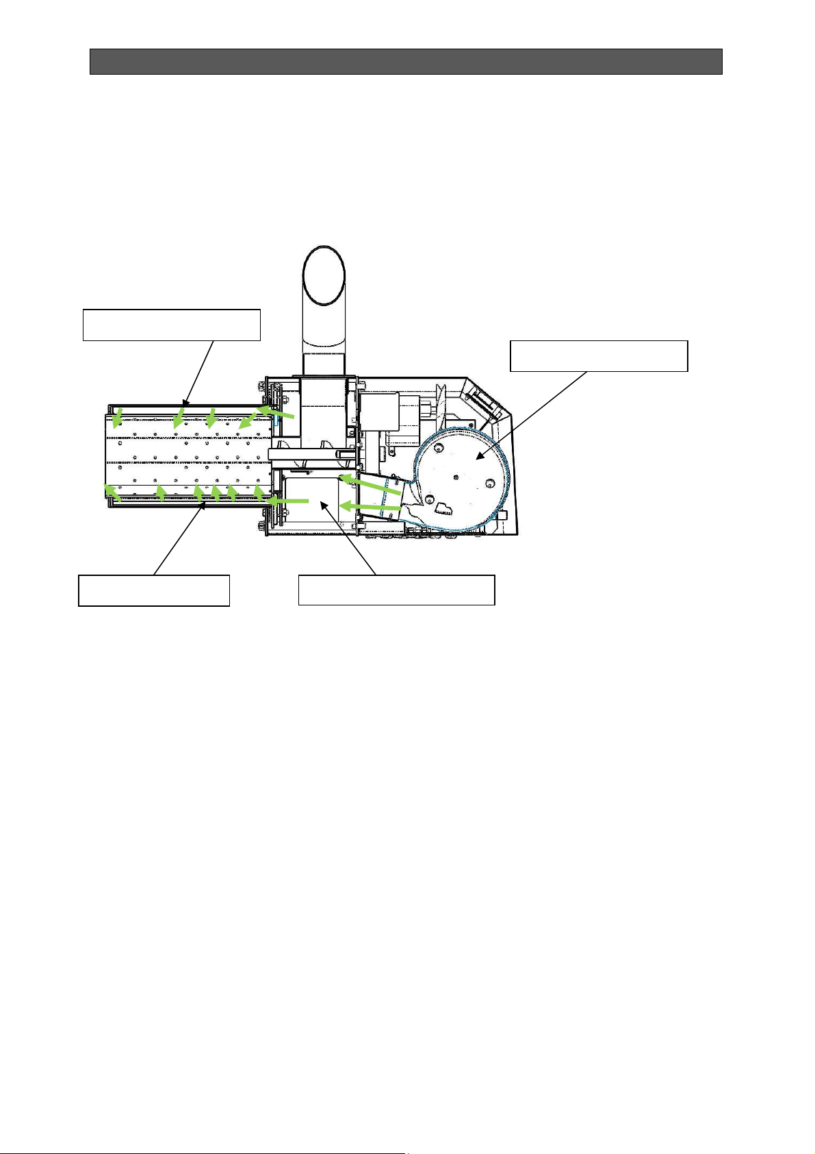
Figure 12 presents the diagram of primary and secondary air supplying in the tube pellet
burner with rotary self-cleaning Bisolid GP xx R tsc.
Figure 12. Diagram for firing air supply in the burner
Secondary air
Fresh air fan
Primary air Air distribution box
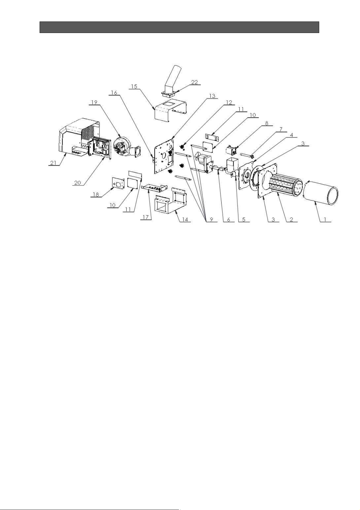
The diagram of the main components of a tube pellet burner with rotary self-cleaning Bisolid
GP xx R tsc is shown in Figure 13.
Bisolid Automat OM-BAV04/10/2017/EN
29
Page 30
INSTALLATION, OPERATION AND MAINTENANCE MANUAL
Figure 13. Diagram of the main components of burner Bisolid GP xx R tsc
1. External tube - 1 pc.
2. Internal tube – 1 pc.
3. Front flange – 1 pc.
4. Combustion group – 1 pc.
5. Inlet pipe for pellets – 1pc.
6. Feeding group – 1 pc.
7. Drive shaft – 1 pc.
8. Motor-gear – 1 pc.
9. Restrictive axis – 4 pcs.
10. Lid – 2 pcs.
11. Cover bracket – 2 pcs.
12. Poll – 4 pcs.
13. Main flange – 1 pc.
14. Main shield – 1 pc.
15. Shield cover 1 – 1 pc.
16. Stiffening profile – 2 pcs.
17. Supporting stiffening – 1 pc.
18. Contact profile – 1 pc.
19. Fan group – 1 pc.
20. PC board – 1 pc.
21. Cover– 1 pc.
22. Transition for pellets – 1 pc.
Bisolid Automat OM-BAV04/10/2017/EN
30
Page 31

INSTALLATION, OPERATION AND MAINTENANCE MANUAL
3.1. TUBE PELLET BURNER TECHNICAL DATA
The technical data for tube pellet burner Biolid GP xx R tsc are given in Table 6.
Table 6. Technical data of tube pellet burner Bisolid GP xx R tsc
Parameter Dimension Value
Preferred fuel - Woden pellets
Wood pellets category
according to standard
EN ISO 17225-2:2014
Used pellets categories
(according to the manufacture
company’s classification)
Wastes after complete fuel
burning
Power supply voltage - L1, N, PE, 50Hz; 230VАС;
In nominal
Electrical
consumption
Electrical power W
Electrical protection -
mode
In ignition
mode
-
-
-
A
A 5
The quantity depends on the pellets ash content and
on the burner’s operation mode
< 100
A1, A2, B
A, AB, B, BC, C
0.3
+500
(+ at ignition)
IP20
Bisolid Automat OM-BAV05/02/2018/EN 31
Page 32

INSTALLATION, OPERATION AND MAINTENANCE MANUAL
4. OPERATION INSTRUCTIONS
4.1. OPERATION OF BOILER BISOLD AUTOMAT
The boiler should be maintained only by adult persons, preliminary acquainted with the boiler
operation and maintenance. The boiler service and maintenance personnel should strictly
comply with the manual and should only commission the boiler, adjust the temperature of the
thermal power regulator, decommission the boiler and conduct ongoing monitoring of ts
operation. After commissioning the boiler, the service technician should acquaint the user with
the boiler operation and maintenance. Unattended children are not allowed near the boiler.
Any activity on the construction of the boiler, which might endanger the life and health of the
maintenance personnel or of persons present in the boiler room, is strictly forbidden.
The boiler should be operated at a maximum water temperature of 90 oC and is subject to
ongoing control. Use of flammable liquids for easy firing as well as any activities related to
increasing boiler rated power (overloading) are strictly forbidden. Positioning of flammable
objects on top or near the boiler is not allowed. The ash should be taken out in fireproof
container with cover.
In case of danger from penetration of flammable vapors or gases in the boiler
room or any activities that might lead to fire or explosion (bonding flooring,
varnishing with flammable paints or others), the boiler should be
decommissioned before starting any of these activities.
4.2. SAFETY OPERATION OF THE BOILER
Relevant safety instructions should be observed when operating the boiler. Bisolid Automat
Boiler should not be used for any other purposes except for those indicated in this manual.
When operating the boiler Bisolid Automat, always a heating circuit has to be
included in which the water is circulated. If the heating radiators are equipped
with thermostatic valves (or other control components), which close the
circulations water flow. As a result of this process it is possible that the
generated heat energy, from the fuel final combustion, can’t be adopted by the
heating system (can’t be unloaded) and to lead to overheating of the appliance.
Therefore in case the boiler Bisolid Automat is operated in heating systems with
radiator regulation valves, it is necessary not to completely close the radiator
valves, but to adjust them to minimum value. Also one of the radiators should
not be equipped with regulation valve, in order to ensure adoption of the heat
energy generated during the process of final combustion.
Boiler surface should be cleaned only with standard inflammable cleaners. Positioning of
objects made of flammable materials near the boiler at an unsafe distance is not allowed.
It is not allowed to store flammable materials (wood, paper, oil, diesel oil, petrol and other
readily flammable materials) in the boiler room. The minimum allowed distance between
boiler’s outer parts and the flue pipe and any average or not readily flammable materials
(which dye out after firing without any additional heat energy), should be not less than 100
mm.
The allowed distance from readily flammable materials (which continue to burn after removal
of the firing source) should be minimum 200 mm.
Bisolid Automat OM-BAV05/02/2018/EN 32
Page 33

INSTALLATION, OPERATION AND MAINTENANCE MANUAL
Removal of solid waste, combustion process products, out of the ash tray should be
performed using the ash box. The ash box (ash tray) should be emptied in good time before
fully filled. All ash box related activities should be performed using a handle, situated on its
front. After removing the box from the boiler the ash should be dumped in a preliminary
prepared fireproof container. When handling or operating use gloves as protective equipment.
When installing the boiler and its safety and control components, do not forget
that all installation works should comply with the safety at work principles.
Bisolid Automat OM-BAV05/02/2018/EN 33
Page 34
INSTALLATION, OPERATION AND MAINTENANCE MANUAL
5. BOILER BISOLID AUTOMAT COMMISSIONING
5.1. BOILER INSPECTION BEFORE COMMISSIONING
Before commissioning the boiler, the service technician should check:
Whether the installation comply with the design.
Whether the boiler is filled with water and under pressure and weather there are
leakages in the heating system.
The connection of the pellet tube burner to the boiler.
Boiler connection to the chimney – the pipe connection should be approved by an
authorised service specialist.
Functioning of the heating regulators.
The service technician should train the user how to control the boiler and
should fill-in the exact date of commissioning the boiler in the warranty card.
When installing a Bisolid Automat boiler on the heating system always observe
the requirements indicated in section 9.5 for the installation of the boiler
equipment excess heat release.
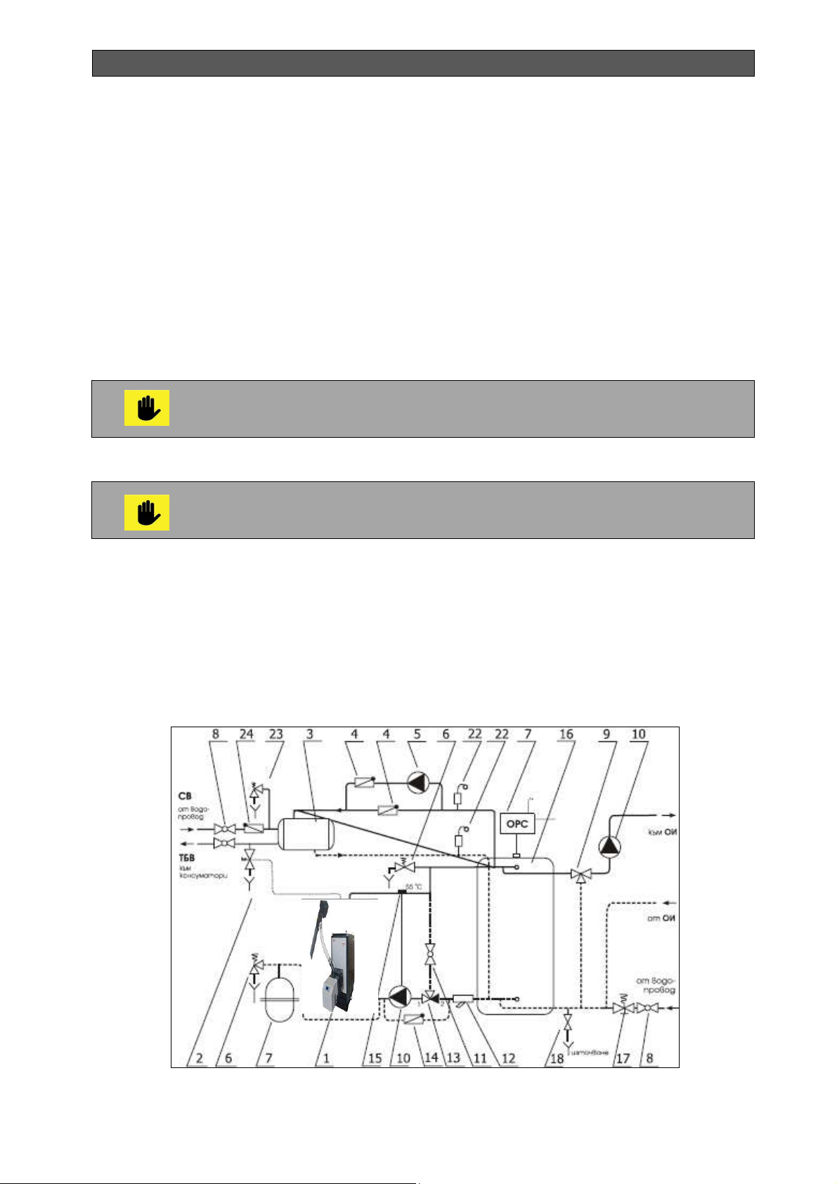
5.2. EXEMPLARY PRINCIPAL HYDRAULIC SCHEME
Exemplary principal hydraulic scheme for connecting the hot water boiler series Bisolid
Automat to the heating system with OPENED expansion vessel is shown in Figure 14.
Figure 14. Exemplary principal hydraulic scheme for connecting boiler
Bisolid Automat to heating system
Bisolid Automat OM-BAV05/02/2018/EN 34
Page 35

INSTALLATION, OPERATION AND MAINTENANCE MANUAL
1. Boiler Bisolid Automat
2. Safety valve
3. DHW boiler
4. Non-return valve
5. Circulating pump 1
6. Safety valve
7. Open or closed expansion vessel
8. Ball valve
9. Three-way mixing valve
10. Circulating pump 2
11. Ball valve
The exemplary hydraulic scheme is for information ONLY, and can not be used
as practically implemented hydraulic scheme.
Completion of the installation and implementation of hydraulic tests of heating
boiler Bisolid Automat shall be recorded in the report for commissioning
and adjustment where mandatory the fields are filled in with the necessary
information.
12. Water filter
13. Thermovalve TV
14. Non-return valve
15. Contact thewrmostat
16. Heat accumulator
17. Automat for filling of water
18. Tap for filling and draining
22. Automatic air vent with valve
23. Safety valve
24. Non-return valve
5.3. FILLING AND DRAINING THE HEATING SYSTEM
The system may be filled with water or drained only if the water corresponds to the parameters
of the EN standards. The water should be clean, colorless, without suspended particles, oils
and chemically corrosive substances, and it should not be acidic (рН factor must be higher
than 7.0). First of all a comprehensive washing of the entire heating system should be
performed.
Water amount in the system should not be decreased or drained except in the
cases when the boiler is being repaired and there is risk of freezing. An
antifreeze fluid can be added into the water system representing 15% of the
total water quantity (see anti-freezing fluid instructions of the supplier).
Non-fulfillment of the above mentioned instruction might result in clogging the
heat-exchanger. During the heating season the water volume in the heating
system should be kept constant. When topping up water, be careful and avoid
intake of air into the system. Water should never be drained out of the boiler
or the heating system, except if it is absolutely necessary, like during repair and
other. Draining and refilling the system with water increases the risk of
corrosion and boiling stone (scale).
5.4. CONDENSATION AND TARS
In boiler initial commissioning the walls of the boiler condensates, which drains into the
combustion chamber. Such condensation on the walls might cause doubt that the boiler
“
leaks”. The condensation disappears after depositing of ash on the inside walls, which is
usually achieved after 2 to 4 ignitions. When operating at reduced power, at low water
temperature in the boiler and low flue gas temperature, condensation forms on the inside
Bisolid Automat OM-BAV05/02/2018/EN 35
Page 36

INSTALLATION, OPERATION AND MAINTENANCE MANUAL
boiler walls, which drains into the combustion chamber. As the flue gas condensation point is
o
65
C, the condensation forms only when the gases cool down in the middle layer of the boiler
walls, where the temperature is lower than 65 oC. If condensation affects the combustion
chamber as well, this means that the used fuel is too wet. In such a case, the condensate may
leak into the combustion chamber even if the water temperature is higher than 65oC. Tar forms
under similar conditions - low thermal power, low temperature and in case of improper
regulation of the combustion process (insufficient amount of secondary air).
The tar is removed from the walls of the boiler using the provided tar scraper, but only when
soft. This can be achieved at boiler water temperature around 90 oC. Such temperature,
however, quickly takes the heaters out of their nominal mode of operation. Therefore, quickly
burning soft firewood is recommended as optimum fuel.
If you decide to install an expansion tank to prolong boiler life, before that
eliminate the possibility of low temperature corrosion along the fuel pass by
maintaining boiler temperature above the dew point of 65 oC. This can be
achieved by a mixing device. If low temperature corrosion is not limited, the
boiler corrodes while the expansion tank, in most of the cases, reduces the life
of the boiler body as a result of the pressure and the dynamic load on the boiler
walls. Only service providers, duly authorized to perform such activities, have
the right to install expansion tanks.
At boiler initial firing condensation may occur. This should not trouble the user
as this is normal - especially when burning firewood with higher moisture. The
boiler "dries" when reaching normal mode of operation.
5.5. BOILER MAINTENANCE
The combustion grate is cleaned by moving the lever forward and backward in a range of 1015 cm by lifting the control lever. If you want to do a thorough cleaning after completion of the
combustion process, the grate is drawn fully forward with the help of the lever of the grate.
The boiler should be used only up to its rated thermal power. Overheating the boiler results in
limiting the life of the heat source, this is not recommended by the manufacturer. The boiler
and the heating system should be dimensioned so that to avoid continuous operation with inlet
water temperature of less than 65 oC - the dew point.
If the boiler works continuously in this mode of operation, its lifetime is reduced, resulting in
heavy contamination and tar smearing on the boiler and the chimney, which results in limited
chimney draft and creates other preconditions to degrade performance? For this purpose, we
recommend during transitional seasons (spring, autumn) to fire the boiler for a short period of
time at full thermal power, in order to burn the deposits and to dry the chimney.
The manufacturer does not recommend, under no circumstances, to burn
sawdust, which significantly reduce the lifetime of the boiler.
Bisolid Automat OM-BAV05/02/2018/EN 36
Page 37

INSTALLATION, OPERATION AND MAINTENANCE MANUAL
5.6. BOILER CLEANING AND MAINTENANCE
After continues operation, soot and ash accumulate on the boiler walls, which reduces the
performance of the equipment. The quantity of soot and the eventual tar depend on the
operation of the boiler, the type of fuel used, the parameters of the chimney draft and the
outlet water temperature. Cleaning of the boiler should be carried out according to need and
operating conditions, but at least once a week.
After stopping its operation, the ash from the grate should be cleaned. The smoke damper is
adjusted in the upper position and the heat-exchanger cover is taken off. Cleaning of the heatexchanger is done with the cleaning tools provided with the boiler (steel scraper and brush).
The soot fallen under the heat-exchanger is removed through the soot door. After cleaning the
boiler, the ash door is returned to its initial position.
During cleaning, it is recommended to check the condition of the ceramic blocks in the
combustion chamber. Damaged blocks are replaced with new ones.
Please strongly concider the timely closing of the flue gases flap of the boiler.
The ash must be stored (the ash has to be taken out by using appropriate
gloves) in fireproof reliable containers and to be transported to open space.
Other waste should not be stored in this container.
Maintenance of boilers series Bisolid Automat is done daily, periodically or annually.
In daily maintenance, the user must clean the unburned residues in the combustion chamber;
clean the ash gathered in the combustion chamber and dumps the ash-box (ash-tray).
For effective use, to prevent possible problems with the operation and for optimum life of the
boiler, it is very important that the user performs periodic maintenance of the equipment. A
periodical check on every 3 months is recommended. Such checks should be performed by
authorized service technicians and should include the following activities:
Check boiler’s combustion chamber and flue pipe, including the chimney. They
should be cleaned if necessary.
Check for leakages of inlet - outlet water, in and out of the boiler and water pipe
connections.
Check fittings including valves and flaps.
Check the fresh air fan of the pellet burner.
Check the circulation pimps.
Visual check of the grate.
Operation and safety control checks of the boiler hydraulic system.
Check the unloading valve.
The annual preventive maintenance of the boiler should be carried out only by authorized
technicians, before the start of the heating season. Before calling the service technicians the
user should clean the flue pipe and the chimney. The annual preventive maintenance carried
out by authorized service technicians includes the following checks and activities:
Position of the fuel hopper and the combustion chamber, insulation and insulation
ropes.
Boiler testing at operating pressure for adjustment of combustion by measuring flue
gas parameters if needed.
Checking and cleaning the boiler grate and surfaces from soot and ash.
Bisolid Automat OM-BAV05/02/2018/EN 37
Page 38

INSTALLATION, OPERATION AND MAINTENANCE MANUAL
Testing boiler connections for leakages.
Checking fittings including nozzles, valves, pressure valves for reliable opening and
closing.
Testing and cleaning the water filter if needed.
Checking and cleaning the expansion tank if needed.
Testing the pressure sensor. Cleaning and replacement if needed.
Operation and safety control check of the boiler hydraulic system.
Testing proper operation of the unloading valve.
5.7. TUBE PELLET BURNER CLEANING
The system for cleaning of tube pellet burner with rotary self-cleaning from Bisolid GP xx R tsc
consists of:
Mechanism for tube rotation.
Motor-gear for mechanism rotation.
PC board that controls the mechanism.
The cleaning of the rotary tube pellet burner is carried out in a certain algorithm, in the
combustion process.
The adjustment of the automatic cleaning system of a rotary tube pellet
burner from Bisolid GP xx R tsc must be performed by a certified staff.
In case of a warning alarm message for the failure of the pellet burner, the user
is obliged to check for possible accumulation of fuel in the burner tube and fuel
transport auger and in the presence of fuel to remove it.
The number and frequency of cleaning of the burner depend largely on the
quality of the wood pellets. Fuel is necessary to meet the standard
EN ISO 17225-2:2014, classes A1, A2 and B.
5.8. TUBE PELLET BURNER MAINTENANCE
The time for cleaning (rotating tube) of the combustion chamber of rotary tube pellet burner
Bisolid GP xx R tsc and cleaning the tube itself depends on the type and quality of the used
fuel.
Before taking action on cleaning, servicing and repair, the pellet burner must
be switch off from the electricity supply.
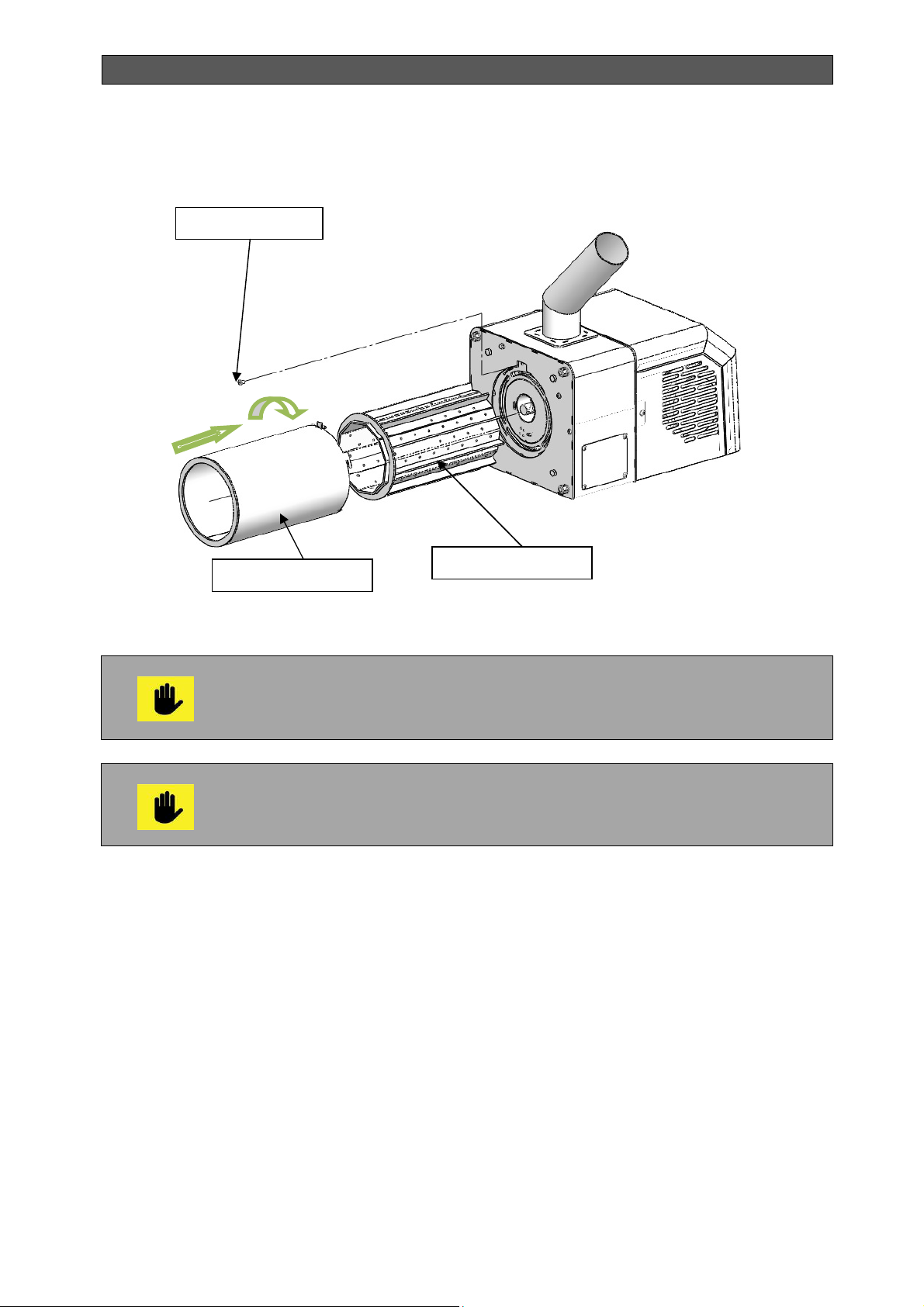
When cleaning the tube of pellet burner Bisolid GP xx R tsc need to be removed combustion
head of the burner, as shown in the diagram in the following figure.
Bisolid Automat OM-BAV05/02/2018/EN 38
Page 39
INSTALLATION, OPERATION AND MAINTENANCE MANUAL
Figure 15. Diagram of the burner main module with dismantling tube
Stopper bolt
External tube
The tube of pellet burner is removed after cooling of the base module so that
be safety in tube handling in its cleaning. During the cleaning should pay
particular attention to overall cleaning of the holes through which air supply
and that provides efficient combustion process and optimum cooling
The ash cleaning from the burner and boiler and also removal of the ash
container must be performed by personal safety means (cloves and cuffs).
We recommend in dismantling and mounting works to be used respective
tools.
The burner tube is positioned against the stopper bolt supporting the tube to the main part of
the burner. The dismantling of the stopper bolt is done by developing of the bolt, after which
the tube is rotated in the direction counterclockwise to the front part of the burner and pull out.
Internal tube
.
Bisolid Automat OM-BAV05/02/2018/EN 39
Page 40
INSTALLATION, OPERATION AND MAINTENANCE MANUAL
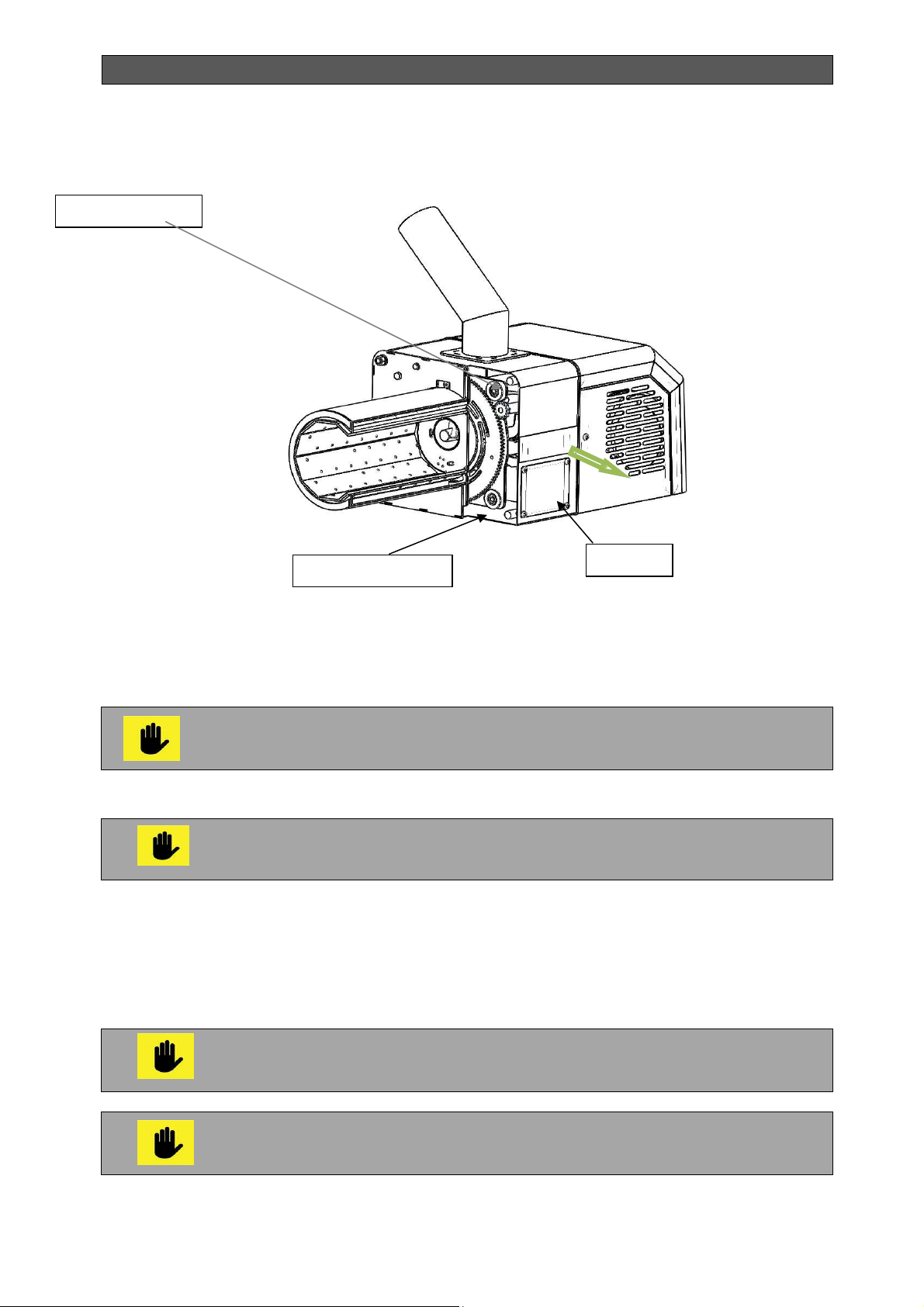
Figure 16. Cross-sectional view of the burner tube, showing the position of the tube relative to
the main part of the burner
Stopper bolt
It is carrying out inspection and cleaning of the air box of the tube pellet burner whose cover is
shown in the diagram in Figure 16. Access to the air box is possible from both sides of the
burner due to the presence of two lids.
The maintenance of a boiler should only be performed by adult persons who
are familiar with the instructions of the equipment operation.
Air box
Lid
When the tube pellet burner is switched off by the user it is necessary waiting
for the complete combustion of residual fuel according to the parameters
mentioned in Table 13.
5.9. PELLET BURNER SERVICING
The regular tube pellet burner servicing by the user guarantees efficient, economic and
reliable operation of the appliance.
Before taking action on cleaning, servicing and repair, the pellet burner must
be switch off from the electricity supply.
During the cleaning of a tube pellet burner the user must use personal
protective means (gloves and cuffs).
Bisolid Automat OM-BAV05/02/2018/EN 40
Page 41

INSTALLATION, OPERATION AND MAINTENANCE MANUAL
The user has to periodically, at least once per day or longer, depending on the fuel ash
content, but no longer than five days of operation, to switch off the burner. This measure
guarantees effective after-burning of the fuel and combustion chamber cooling.
After the pellet burner cools down the ash and/or slag must be cleaned from the combustion
chamber fire-grate. The flexible pipe connecting the fuel transport auger and the burner fuel
inlet pipe must be cleaned from dust at least once per week.
Dust depositing on the flexible pipe walls can lead to distortion of the fuel
feeding, ignting the dust as a result of emergency situation, in consequence of
which hot flue gasses might pass through it.
It is necessary that the user is fully introduced with the information presented in
the current operation manual, in connection with the pellet burner operation, its
control and servicing.
5.10. BOILER REPAIR
The user may only carry out replacement of spare parts as per the attached list. Large scale
repairs should be performed only by an installation or service provider.
Boiler service personnel is entitled to perform only repair activities that do not require special
qualification and represent simple replacement of parts such as grates, sealing ropes, ceramic
blocks, secondary air pipe and smoke damper. All other failures should be repaired by an
authorized service provider.
Only genuine spare parts should be used when repairing the boiler.
5.11. WARRANTY AND WARRANTY TERMS AND CONDITIONS
We pay attention to users that commissioning and service maintenance of all Bisolid Automat
hot water boilers should be performed by a specialized installation company. Otherwise, any
eventual warranty claims shall not be accepted. Warranty issues are claimed immediately after
detecting the defect. The warranty period is indicated in the warranty card, which is provided
as a basic accessory to the boiler and is determined by precise following the instructions in the
current installation, operation and maintenance manual. The Buyer has to submit a warranty
claim in writing to the Seller or to an authorized service provider.
The manufacturer reserves the right to make changes, related to the product
technical optimization.
5.12. BOILER ACCESSORIES UPON DELIVERY
Bisolid Automat series hot water boilers are delivered fully assembled and functionality tested.
Bisolid Automat boilers accessories upon delivery are presented in Table 7.
Bisolid Automat OM-BAV05/02/2018/EN 41
Page 42

INSTALLATION, OPERATION AND MAINTENANCE MANUAL
Table 7. Accessories of Bisolid Automat series boilers
No Name
1 Bisolid Automat hot water boiler 1
2 Tube pellet burner Bisolid GP хх R tsc 1
3 Bisolid pellet auger 1
4 Other suitable fuel loading door 1
5 Ash cleaning door 1
6 Grates 2
7 Ash tray 1
8 Electrical panel 1
9 Cleaning tool - scraper 1
10 Cleaning tool - brush 1
11 Cleaning tool - hook 1
12 Flue gas sensor with transmitter 1
13 Operation manual 1
14 Warranty card 1
Available spare parts at request:
Sealing rope for the fuel feeding door.
Cast-iron grate (two identical)
Sealing rope for the ash cleaning door.
Ash cleaning door - set.
Soot door, soot door sealing.
Flue gases flap.
Set of heat-exchanger covers.
Heat-exchanger cover sealing rope.
Special requirements for spare part should be coordinated with the manufacturer.
When sending spare parts requests, please indicate the boiler type, its size,
factory number and year of production.
Spare parts and accessories for the boilers can be ordered to the service technician who
performed the installation or directly to the supplier.
Bisolid Automat
(pcs.)
5.13. ACTIONS AFTER COMPLETION OF THE BOILER LIFE-CYCLE
After completion of the life-cycle of a Bisolid Automat series hot water boiler, its destruction
should be performed in an environmentally-friendly manner. For this purpose, the boiler and
the pellet tube burner are dismantled and the modules are brought to the recycling centers as secondary raw materials, in compliance with the principles of separate waste collection.
Bisolid Automat OM-BAV05/02/2018/EN 42
Page 43

INSTALLATION, OPERATION AND MAINTENANCE MANUAL
6. BOILER OPERATION AND CONTROL USING PREFERRED FUEL
(WOOD PELLETS)
6.1. PURPOSE OF THE TUBE PELLET BURNER
The purpose of the fully automated tube pellet burner with manual cleaning Bisolid GP xx R
tsc as part of the accessories of Bisolid Automat series boiler is to heat sites with small and
medium sizes.
The pellet tube burner is a very good heating solution by burning wood pallets. What is more,
pellet burner Bisolid GP xx R tsc may automatically fire other suitable fuel, used by the user,
like firewood and wood chips, then stop and subsequently, if the boiler other suitable fuel has
been burned out to start automatically burn wood pellets.
The automatic electric ignition, the automatic selection of the thermal power (optimization
mode with room thermostat) and the multi-functional indicator control panel of the pellet tube
burner make it easy and comfortable to use during the heating season.
Pellet burner Bisolid GP xx R tsc is designed to burn wood pallets compliant with standard EN
ISO 17225-2:2014, classes A1, A2 and B with the relevant quality characteristics that are
shown in Table 1 and Table 2. The fuel and air mix in the burner in a controlled way result in
an ecological highly efficient combustion.
The required minimum time for maintenance of tube pellet burner Bisolid GP xx R tsc,
depending on the characteristics and the quality of the wood pellets, is once a week.
The optimum functionality of the equipment depends both on the professionally designed
heating installation and on the precise maintenance of the pellet tube burner.
6.2. PURPOSE OF THE PELLET BURNER CONTROLLER
The controller is designed to provide automatic control of the combustion process and to
adjust the power of the pellet burner, depending on the heating needs of the building or the
premises.
Hot water boilers series Bisolid Automat are designed to work with preferred
fuel (wood pellets) and other suitable fuel (firewood and wood chips). The
working algorithm requires the presence of pellets because the ignition of the
other sitable fuel and optimal burning is assisted by the pellet burner operation.
In principle, it is possible work only with pellets, but the optimal use of the
opportunities of boilers, and heat output becomes both fuels.
It is forbidden directly ignition of hot water boilers series Bisolid Automat using
other suitable fuel (firewood or wood chips) without to be switch on the pellet
burner controller!
Switch on the pellet burner controller before starting operation of the
boiler!
Bisolid Automat OM-BAV05/02/2018/EN 43
Page 44
INSTALLATION, OPERATION AND MAINTENANCE MANUAL
Т
,
P,%
m
in
6.3. OPERATION OF THE PELLET BURNER CONTROLLER
The device can control the following system modules of the pellet burner:
Fuel feed auger 1.
Fuel feed auger 2.
Fresh air fan and flue gases fan.
Electric heater to ignite the pellets.
Cleaner to clean ash.
Boiler circulation pump.
At primary switch on, as well as when switching the power supply off,
the burner goes through a stop procedure.
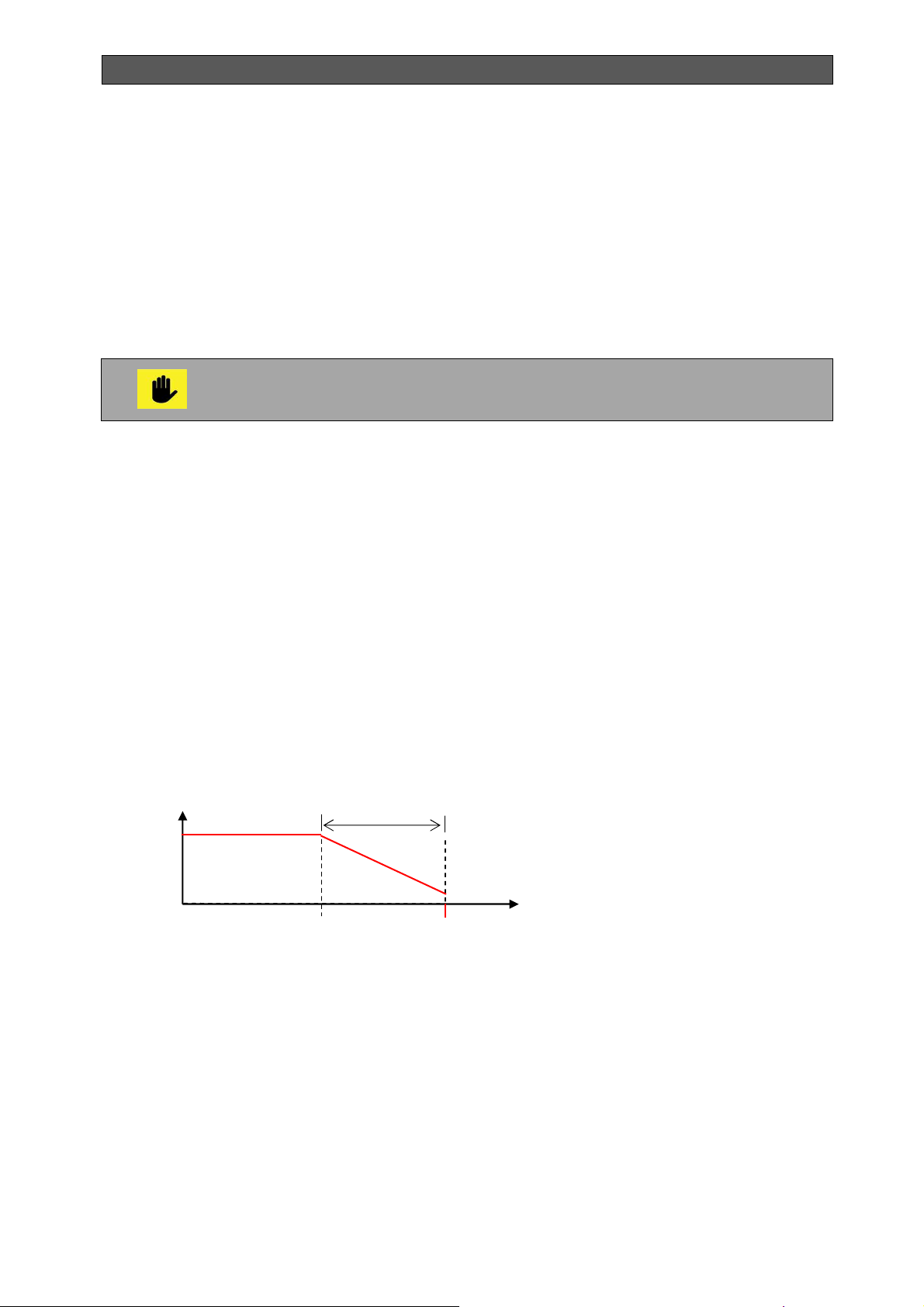
6.4. STARTING THE PELLET BURNER
When missing stop signal or in case of emergency situation and there is difference between
the adjusted and the measured temperature from the To sensor, then the burner starting
procedure initiates. The initial fuel doze is loaded and the ignition switches on.
After establishing the presence of flame the burner heating output increases. When the
modulation zone „Zone_reg” has been reached the burner heating output decreases and
when the desired water temperature or flue gases temperature has been reached the burner
operates at its minimum heating ouput. When higher than the adjusted temperature has been
reached, the system responds with stop procedure.
When the burner is in the modulation mode and the power is reduced accordingly, upon
temperature decrease the power starts to increase automatically.
T
P
ma
x
P
Т_set - zone_reg
zone_reg
Т_set
6.5. STOPPING THE PELLET BURNER
In case of a stop signal, emergency situation or measured temperature above the setup, the
system initiates a stop procedure. It waits until last fuel dose is burned. Next is the time for
ventilation, during which the combustion chamber cools down and the residual ash from the
combustion grate is blown out.
Bisolid Automat OM-BAV05/02/2018/EN 44
Page 45
INSTALLATION, OPERATION AND MAINTENANCE MANUAL
Т
,
OFF
Т
,
OFF
6.6. BURNER GSM CONTROL MODULE (OFFERED AS AN OPTION)
The control of the pellet burner through a GSM module is done by sending SMS commands. It
allows for stopping, starting and current status monitoring. (See Section "SMS Commands")
6.7. METHODS FOR FORMING THE DESIRED TEMPERATURE
6.7.1. MANUAL DETERMINATION OF THE HEATING WATER
ASSIGNMENT (Тb set)
In this case, the assigned values are independent of other factors such as external
temperature and room temperature, a value is selected to be maintained. (See Section
Programming “Service Settings").
There is provided possibility for room thermostat using, and this thermostat to be connected to
the the rear panel of the boiler.
6.7.2. DETERMINATION OF THE HEATING WATER ASSIGNMENT BY
ROOM THERMO-REGULATOR
This mode is applicable only if using contact room thermostats with
"independent outlet". (See Section Programming "Service Settings).
The room thermostat may be used ONLY when operating the boiler with the
preferred fuel (wood pallets) without adding other suitable fuel!
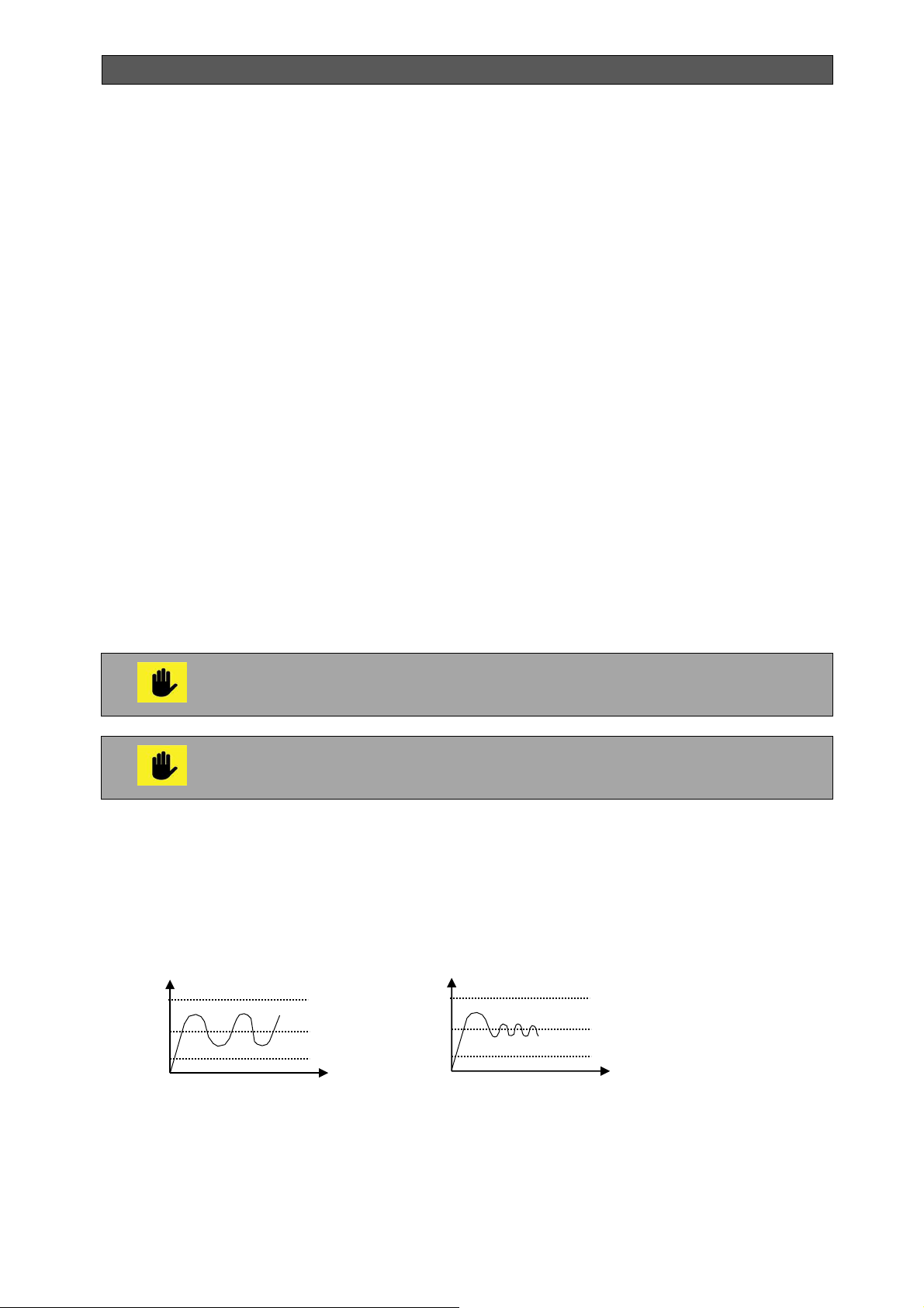
Time for optimization.
When using optimization time, the number of fluctuations of the setup values of the heating
water are decreased, which leads to much better regulation of the heating water. It can be
selected from 0 to 60 min, with a pitch of 5 minutes. (See Section Programming “Service
Settings").
Wmax
W
Wmin
ON
without
Wmax
W
Wmin
ON
with optimization
When the room thermo-regulator is switched on or off and there is no optimization (0 minutes),
the setup values of the heating water are:
At switching on – maximum.
At switching off – minimum.
Bisolid Automat OM-BAV05/02/2018/EN 45
Page 46
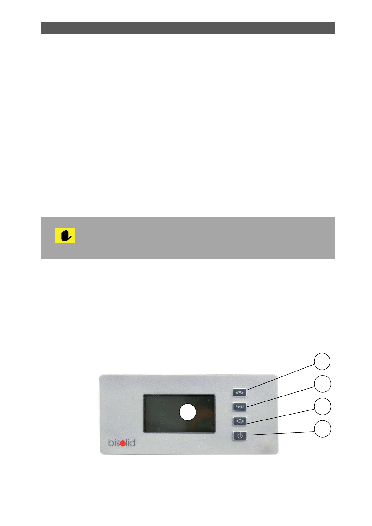
INSTALLATION, OPERATION AND MAINTENANCE MANUAL
When the room thermo-regulator is switched on or off and there is an optimization (5-60
minutes), the setup values of the heating water are:
At switching on
end of the optimization time, only if there has been no switching off during that period.
At switching off – a decrease of the setup values starts, and the minimum setup values
are reached at the end of the optimization period, only if there has been no switching
on during that period.
–
an increase starts and the maximum setup values are reached at the
6.8. TEMPERATURE RESTRICTIONS AND PROTECTIONS
When operating tube pellet burner Bisolid GP xx R tsc it is necessary to consider the following
temperature restrictions and protections:
Minimum setup values of the inlet water temperature.
Maximum setup values of the inlet water temperature.
Water freezing protection.
Boiler overheating and „back-fire” protection.
Circulation pump blocking protection.
Maximum setup values of the temperature of the exhaust gases for main inlet fuel and
for other suitable fuel.
Freezing protection - starts the burner at temperatures below 5 °С.
Boiler overheating and „back-fire” protection – blocking thermostat inlet,
when opening the signal contact, the burner stops.
Protection from blocking the circulation pump – drives/rotates the pump for
5 minutes, in case it has not been operating for 24 hours.
The maximum and the minimum setup values of the heating water temperature delimit the
water supplied to the premises. (See Section Programming “Service Settings").
6.9. PELLET BURNER FRONT PANEL
Figure 17 shows the front panel - intuitive LCD display of a tube pellet burner Bisolid GP xx R
tsc. Parameters indications on pellet burner display are given in Figure 18.
Figure 17. Front panel of tube pellet burner Bisolid GP xx R tsc
1
1. Front panel indication – intuitive LCD display.
2. Changing button “Forward” / or manually switching on/off the pellets transport auger
(if holded for 5 sec. together with additionally known conditions described below).
2
3
4
5
Bisolid Automat OM-BAV05/02/2018/EN 46
Page 47
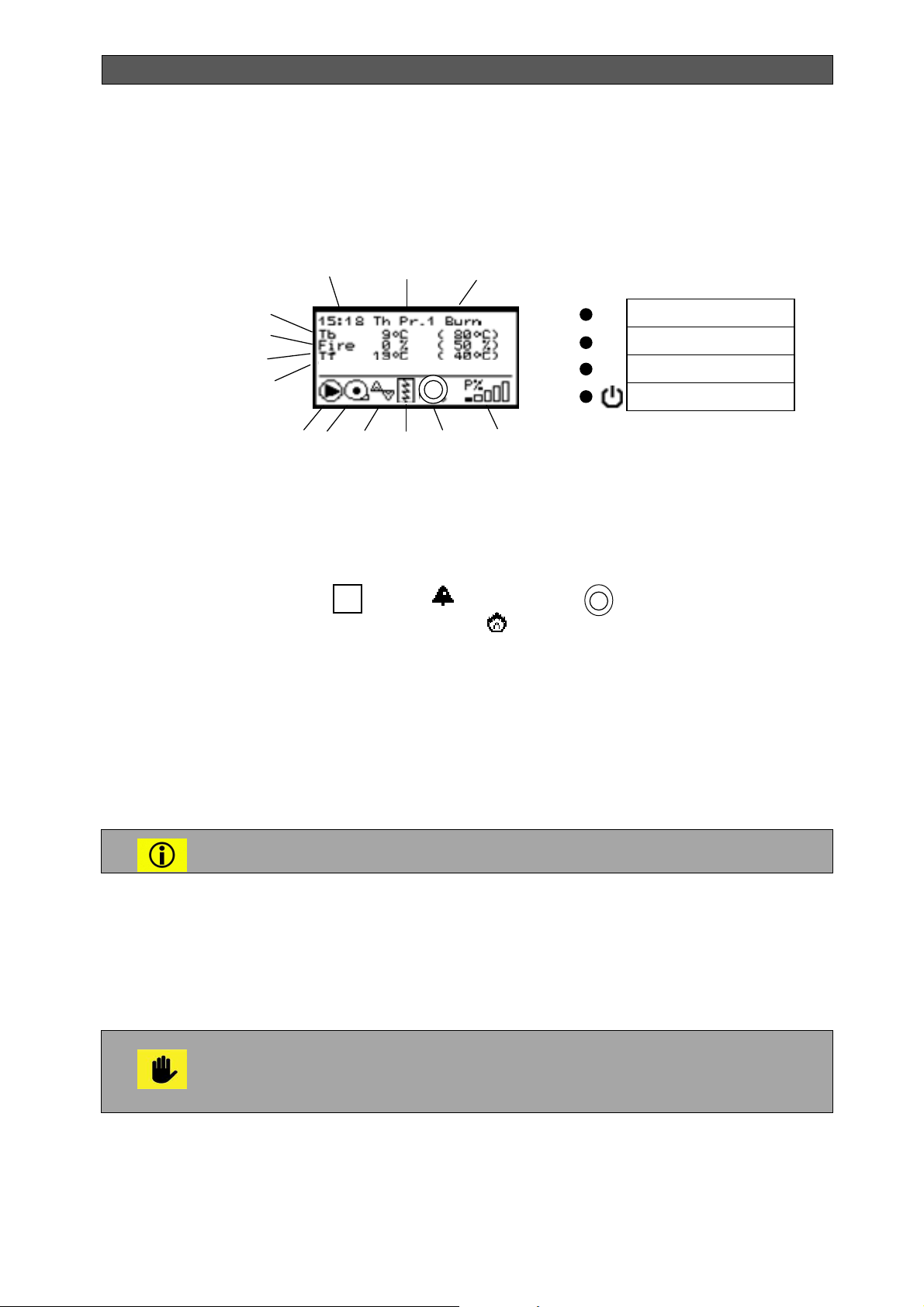
INSTALLATION, OPERATION AND MAINTENANCE MANUAL
1
2
3
4
5
6 7 8
9
10
11
12
13
↑
↓
Н
апред
Н
азад
П
ромяна
ON/OFF
ignition
Forward
Back
Enter/Exit
ON/OFF
3. Changing button “Back”.
4. Button for Enter/Exit from programming mode (user settings), switch ON/OFF (if
holded for 5 sec).
5. Button ON/OFF.
Figure 18. Displey indication of pellet burmer series Bisolid GP xx R tsc
In the basic state the display shows the following parameters:
1. Time and day of the week.
2. Execution of weekly program N ....
3. Stop / Start / Burn - performed procedure.
4. Current exploited power.
5. Indicator room thermostat , alarm or tubus cleaner ;
6. Indicator igniter or for ignition other suitable fuel ;
7. Indicator work auger nimbers 1 and 2 blinks in manual switching.
8. Indicator working fans with nimbers 1 and 2.
9. Indicator working pump.
10. Tfg - temperature flue gas (assignment).
12. Fire - light sensor (assignment).
13. Tb - water temperature.
-/-
6.10. OPERATION (FUNCTIONING) OF THE PELLET BURNER
Only user information is presented in this part of the operation manual.
The information for service specialists is presented separately.
The controller of the tube pellet burner is swithcing on and off:
By pressing and holding the button ON/OFF. When the burner is swithc off then
appears "Stopped".
In the off position when on the display shows one of the above messages by pressing
and holding for about 10 seconds on the button „” can be switched on and off in
manual way pellet auger with aim filling when the auger is empty.
Before manually switching on of pellet burner you have to verify that the burner
is burnt out.
With buttons „” or „” scroll until on the display is shown the menu with the desired
parameters, then press „
For choice of settings, scroll move the cursur „*” with buttons „” or „” to make
change and return to choice of settings press button „”.
”:
Bisolid Automat OM-BAV05/02/2018/EN 47
Page 48
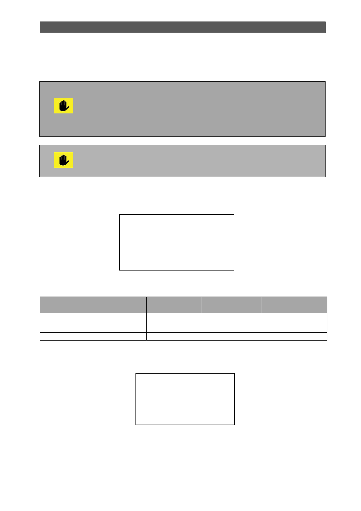
INSTALLATION, OPERATION AND MAINTENANCE MANUAL
The setting which changes startsto blink, with buttons „
net value.
After completing the settings, select „EXIT” and press button „” to save the
changes.
The controller (the pellet burner) may be switched on and off by the front panel
or by the remote controller inlet. A START key is plugged-in to the remote
controller with two stable positions.
WE RECOMMEND TO START AND STOP THE PELLET BURNER USING
THIS START KEY! The controller is switched off irrespective of the place
where the command STOP has been initiated, but can only be switched
on when the command START appears in both places.
The burner SHOULD NOT SWITCH OFF to complete combustion the other
suitable fuel (firewood, wood chips) into the combustion chamber of the boiler!
While NOT FULLY BURNT EMBERS OF WOOD OR WOOD CHIPS, pellet
burner SHOULD NOT BE SWITCH OFF OR DISCONNECT!
” or „” you can change the
6.10.1. USER`S SETTINGS
Table 8. Parameters of the pellet burner user`s settings
Fuel Pellet&Wood
time&d ay 08:30 Fr
Language Eng
User’s Settings
EXIT
Name Indication Limit Factory
settings
Fuel type Fuel Pellet&Wood Pellet&Wood
Current hour and day time&day hh/mm/d
Language Language Eng / Бul Eng
6.10.2. WEEKLY TIMER
Weekly timer
*Program 1
00:00 to 24:00
SuMoTuWeThFrSa
EXIT
Bisolid Automat OM-BAV05/02/2018/EN 48
Page 49
INSTALLATION, OPERATION AND MAINTENANCE MANUAL
Table 9. Weekly timer setup parameters
Program number Program 1 - 4
Interval
Day of the week SuMoTuWeThFrSa
Turning off a weekly program is indicated by Pr.0, and when in operation the number of the
active program is displayed (Pr.1 – Pr.4).
The selection of a flashing period indicates the duration of the program. The selected program
can apply for only one day, for a period from Monday to Friday, Saturday and Sunday and for
the entire week. The flashing indicator shows the selected option.
Name Indication Limit
00:00 – 24:00
Su – Sa
(from Sunday to
Saturday)
To allow operation of the controller, a working interval should be set on one
of the four programs at least. When setting up identical starting and closing
time of the interval, the program is inactive.
6.10.3. ALARM MESSAGES
The presence of an alarm message during operation of the pellet burner is indicated by an
icon .
No Fire OK
Low Tb OK
In BT OK
In FC OK
Table 10. Information for the alarm messages
Name Indication Status Recovery
No flame No Fire OK / Err Switch off and on
Risk of freezing Low Tb OK / Err Increasing temperature
Overheating
(activated blocking
thermostat)
No air flow (flow device) switch off pressure switch
or Hall sensor
In BT OK / Err Switch off and on
In FC OK / Err Switch off and on
OK - normal condition, Err - alarm.
In case of a warning alarm message fault of pellet burner, the user is obliged
to check for possible accumulation of fuel in the burner tube and fuel transport
auger and in the presence of fuel to remove it.
Alarm
Bisolid Automat OM-BAV05/02/2018/EN 49
Page 50
INSTALLATION, OPERATION AND MAINTENANCE MANUAL
о
о
о
о
о
о
о
6.11. SERVICE SETTINGS
When using the controller service settings of the pellet burner, the access is allowed by a
password. The password is reactivated after exiting the menu, if within 15 seconds no button
is pressed.
The service seatings procedures of the pellet burner are password protected
and can be applied only by trained service specialists, disposing of
additional information.
In the transitional seasons it is recommended to operate the boiler ONLY with
wood pellets, in order to avoid the danger of overheating when the used fuel is
in the form of wood or wood chips.
6.11.1. IGNITION SETTINGS
Load 90 s
Blowing 2 m
Fire time 8 m
Preheat 100 s
Fan1 48 %
Inflame 120 s
Ignition settings
Table 11. Ignition settings of pellet burner
Ignition settings
Т set 70 °C
Zone reg. 10 °C
Tfg set 160 °C
Zone_reg Tfg 20 °C
Tubus work 0 %
EXIT
Name
Time for loading Load 2 – 480 s 20 s 20 s 20 s 20 s
Time for blowing Blowing 0 – 10 m 2 m 2 m 2 m 2 m
Time for flame
occurrence
Time for preheating Preheat 0 – 180 s 20 s 20 s 20 s 20 s
Fan for fresh air Fan1 20 – 100% 70% 70% 70% 70%
Time for inflame Inflame 60 – 600 s 120 s 120 s 120 s 120 s
Water temperature T set 0 - 90
Zone regulation of Tк Zone reg 0 - 30
Flue gases temperature Tfg set 100- 400
Zone regulation of Tfg Zone reg
Tubus operation Tubus
Indication
Fire time 1 – 15 m 3 m 3 m 3 m 3 m
Tfg
work
Limit
С 70 оС 70 оС 70 оС 70 оС
С 5 оС 5 оС 5 оС 5 оС
0 – 30 °C 10
0 – 100% 0% 0% 0% 0%
Factory
settings
Bisolid
Automat 25
С 200 оС 200 оС 200 оС 280 оС
С 10
Factory
settings
Bisolid
Automat 35
С 10
Factory
settings
Bisolid
Automat 45
С 10
Factory
settings
Bisolid
Automat 60
С
Bisolid Automat OM-BAV05/02/2018/EN 50
Page 51

INSTALLATION, OPERATION AND MAINTENANCE MANUAL
6.11.2. BURN MODE SETTINGS
Load 2 - 8 s
Pause 14 - 14 s
Fan1 48 - 100 %
Feeder 2 + 5 s
Min<Burn>Max
Таблица 12. Burn mode settings of preferred fuel (pellet burner)
Min<Burn>Max
Tubus per 10 s
Tubus work 10 %
EXIT
Name
Time for loading Load 1 – 240 s 2 – 5 s 2 – 6 s 2 – 7 s 4 –10 s
Pause-time for
burning
Fan for fresh air Fan1 20 – 100 % 40 – 80 % 40 – 85 % 45 – 90 % 50 – 80 %
Extra time for auger 2
operation
Tubus period Tubus per 0 – 240 s 35 s 35 s 35 s 35 s
Tubus operation Tubus work 0 – 100 % 10 % 10 % 10 % 10 %
Indication
Pause 1 – 240 s 17 – 16 s 17 – 12 s 17 – 8 s 15 – 6 s
Feeder2+ 0 - 250 s 18s 18s 18 s 18 s
Limit
Factory
settings
Bisolid
Automat 25
Factory
settings
Bisolid
Automat 35
Factory
settings
Bisolid
Automat 45
Factory
settings
Bisolid
Automat 60
6.11.3 STOP MODE SETTINGS
Таблица 13. Stop mode settings of pellet burner
Stop settings
*Burn out 5 m
Fan1 100 %
Cleaning 10 s
EXIT
Name
Time for burn out Burn out
Fan for fresh air
Cleaning Cleaning 0 – 240 s 90 s 90 s 90 s 90 s
Indication
Fan1
Limit
0 – 15 m
20 - 100 %
Factory
settings
Bisolid
Automat 25
1 m
60 %
Factory
settings
Bisolid
Automat 35
1 m
60 %
Factory
settings
Bisolid
Automat 45
1 m
60 %
Factory
settings
Bisolid
Automat 60
1 m
60 %
In boilers Bisolid Automat 25, Bisolid Automat 35, Bisolid Automat 45 and
Bisolid Automat 60 the fan is equipped by flap closed on ½.
Bisolid Automat OM-BAV05/02/2018/EN 51
Page 52

INSTALLATION, OPERATION AND MAINTENANCE MANUAL
6.11.4. COMMON SETTINGS
FC delay 30 s
Fire set 30 %
Tpump set 40 °C
Pulse/rev 0
Table 14. Common settings of pellet burner
Name Indication Limit Factory
Delay of response of the flow
sensor
Assignment of light sensor Fire set 0 – 99 % 30 %
Assignment pump switch on Tpump set 10 – 70 °C 40 °C
Common Settings
settings
In FC 1 – 240 s 30 s
Pulse revolutions Fan1 pulse/rev 0 - 12
0 - inactive
1
6.12. SMS COMMANDS
The GSM module is optional and it is connected to „CON7” of the indicaiion board. When
available, the GSM symbol appears on the indication. The SMS commands should be with
Latin letters using only capital or only small letters.
Example: BSTOP and bstop - correct, Bstop - wrong.
Table 15. Description of pellet burner GSM control commands
Name Indication Action
Stop BSTOP Stops the burner - identical to ON / OFF button
Start BSTART Starts the burner - identical to ON / OFF button
Current status BINFO Sends an SMS with the current status
Emergency phone
number
BSTOP and BSTART commands have the same effect as ON / OFF button and when turned
on, the weekly program runs. In case of emergency, if no telephone number is recorded, a
check is performed for the last telephone number that has sent an SMS and if no such number
the notification is not sent. When SMS command is received, a reply SMS is sent to the
number that has sent the command.
BPHONE Records the telephone number from which the
message has been sent and in case of missing
flame, missing air flow or activated blocking
thermostat sends a notification.
Bisolid Automat OM-BAV05/02/2018/EN 52
Page 53
INSTALLATION, OPERATION AND MAINTENANCE MANUAL
6.13. PELLET BURNER ELECTRICAL CONNECTIONS
When connecting tube pellet burner series Bisolid GP xx R tsc to the electrical installation, it is
necessary to bear in mind the following technical characteristics (Table 16).
Table 16. Pellet burner technical characteristics
Name
Supply voltage ~230V; 50Hz
Igniter outlet ~230V; 0.30kW
Circulation pump outlet ~230V; 0.35kW
Fan outlets ~230V; 0.25kW
Fuel feed auger outlet ~230V; 0.25kW
Cleaner/tubus rotation outlet ~230V; 0.25kW
Heating water sensor Pt 1000 (-50 до +250 °С)
Flue gas sensor Pt 1000 (-50 до +250 °С)
Flame sensor Photo-resistor
Room thermostat inlet Independent contact
Blocking thermostat inlet Independent contact
Flow sensor / revolutions inlet Independent contact / Hall sensor as an
option
Measurement unit 1 °С
Humidity up to 80.0%
Degree of protection IP00
All the activities related to connecting the pellet burner to the electrical
installation should be performed only by a certified trained person.
Parameter
The pellet burner should be connected to the electrical installation of
the equipment to which it is installed, by observing the safety rules.
Bisolid Automat OM-BAV05/02/2018/EN 53
Page 54

INSTALLATION, OPERATION AND MAINTENANCE MANUAL
7. BOILER OPERATION AND CONTROL WHEN OPERATED WITH
OTHER SUITABLE FUEL
7.1. BOILER FUEL LOADING AND IGNITION
Hot water boilers series Bisolid Automat are designed to work with preferred
fuel (wood pellets) and can utilize other suitable fuel (firewood and wood chips).
The working algorithm requires the presence of pellets because the ignition of
the other suitable fuel and optimal burning is assisted by the pellet burner
operation. In principle, it is possible work only with pellets, but the optimal use
of the opportunities of boilers, and heat output becomes both fuels.
It is forbidden directly ignition of hot water boilers series Bisolid Automat using
other suitable fuel (fire wood or wood chips) without to be switch on the pellet
burner controller!
Switch on the pellet burner controller before starting operation of the
boiler!
The user firstly has to start boiler operation in preferred fuel mode (wood
pellets) With purpose to be heated flue gases system (minimum 30 min. in
nominal heating output) and after that the boiler to go in the operation mode
with other suitable fuel (firewood or wood chips).
Before igniting other suitable fuel in the form of firewood and wood chips in Bisolid Automat
series hot water boilers check:
Water quantity in the heating system.
Sealing of the heat-exchanger cover.
Installed pellet tube burner condition.
The flue gases flap should not be left opened except for 1-2 minutes while
loading the boiler fuel hopper with other suitable fuel (firewood and wood chips).
The role of the flue gases flap is to bring the flue gases out of the boiler fuel hopper to the
chimney only during loading other suitable fuel. The flue gases flap is opened before opening
the door for loading the boiler other suitable fuel to enable extraction through the chimney of
the flue gases collected in the combustion chamber. This prevents smoke in the boiler room
and the risk of inhaling flue gases while loading other suitable fuel in the boiler. The flue gases
flap should no be opened for more than one or two minutes i.e. only during loading the hopper
with other suitable fuel, and should be closed immediately after that.
Do not start the boiler, before connecting the boiler to the chimney.
Check chimney connections before starting the boiler.
Check chimney draft. If the draft exceeds the recommended values install a
draft regulator.
In the transition seasons it is recommended boiler operation ONLY with wood
pellets, in order to avoid the danger of overheating when is used fuel in the
type of firewood or wood chips.
Other suitable fuel ignition (firewood and wood chips) is done as follows:
Bisolid Automat OM-BAV05/02/2018/EN 54
Page 55
INSTALLATION, OPERATION AND MAINTENANCE MANUAL
%
The pellet tube burner may operate both independently and by using other suitable fuel. When
starting the pellet burner, in case no other suitable fuel is added, the burner will operate as a
standard pellet burner. When starting the burner in the event that other suitable fuel is added,
other suitable fuel ignition takes place, then the burner stops and the combustion process
continues with other suitable fuel (firewood and wood chips). The other suitable fuel
combustion process will continue until other suitable fuel is available in the boiler fuel hopper.
In the event that other suitable fuel is exhausted (firewood and wood chips), the pellet burner
will continue to operate maintaining the temperature set by burning wood pallets.
Other suitable fuel can be added during operation of the pellet burner as well.
The pellet burner SHOULD NOT BE SWITCH OFF to the complete
combustion of the other suitable fuel (firewood, wood chips) in the boiler
combustion chamber!
While not completely burnt the embers from wood or wood chips the pellet
burner SHOULD NOT BE SWITCH OFF OR DISCONECTED!
Criterion for successful ignition of the other suitable fuel is the temperature of the flue gases.
When reaching this temperature, the burner modulates its operation to minimum power until
reaching a set water temperature (parameter) and after that it stops. The boiler enters into
other suitable fuel combustion mode. This mode continues until reaching the water
temperature set. When reached, the fan stops its operation and before that it has been in a
modulation mode approaching the temperature set. When the water temperature drops, the
fan is switched on again. It is possible that the burner starts again in case the water
temperature drops down below a set value (parameter).
At first ignition, to control the optimum condition of the flame, quality combustion control is
recommended. It includes monitoring the condition of the smoke from the chimney. Lack of
excessive smoke from the chimney is a sign of quality combustion, but if there is such, this
means that there is a deficiency of secondary air in the combustion chamber.
Bisolid Automat series hot water boilers are not designed to burn coal.
7.2. OTHER SUITABLE FUEL SETTINGS
Other suitable fuel
settings
Tb set 80 °C
dT Fan1 10 °C
Fan1 48 – 100 %
Tfg_lim 60 – 260 °C
Other suitable fuel setting
* Fan3 48 – 100
EXIT
Bisolid Automat OM-BAV05/02/2018/EN 55
Page 56

INSTALLATION, OPERATION AND MAINTENANCE MANUAL
Table 17. Other suitable fuel settings (firewood or wood chips)
Name
Other suitable fuel
assignment
Zone for
revolutions
controling
Fan for fresh air Fan1 15 – 100 % 40 – 100 % 40 – 100 % 45 – 100 % 40 – 100 %
Range of flue
gases temperature
Flue gases fan Fan3 15 – 100 % 48 – 100 % 48 – 100 % 48 – 100 % 48 – 100 %
Indication
Tb set
dT Fan1
Tfg_lim 10 – 400 °C 60 – 220 °С 60 – 230 °С 60 – 240 °С 60 – 320 °С
Limit
5 – 90 °C
0 – 30 °C
Factory
settings
Bisolid
Automat 25
75 °С
10 °C
Factory
settings
Bisolid
Automat 35
75 °С
10 °C
Factory
settings
Bisolid
Automat 45
75 °С
10 °C
Factory
settings
Bisolid
Automat 60
75 °С
10 °C
7.3. BOILER SWITCH OFF
We do not recommend accelerating the combustion process of the boiler. The fuel should burn
completely by itself on the combustion grate.
After switching off the boiler, clean the boiler, take out all combustion residue, empty the
ashbox (ash tray), clean contact surfaces of the feeding door and the ash box, and then close
the feeding door of the boiler and the door of the ash box.
7.3.1. STOPPING THE BOILER FOR A LONG PERIOD OF TIME
When stopping the boiler for a long period of time (at the end of the heating season), the boiler
should be completely cleaned from all unburnt deposits (soot, ash and sludge). Otherwise, the
accumulation of moisture in the unburned gases leads to excessive boiler corrosion.
The boiler can be operated only by adult persons who are well acquainted with
this operation manual.
Turn the boiler off every time, if any (even temporary) danger of presence
of flammable or explosive vapors in the room, from which the combustion air is
supplied to the boiler (for example, from paint during painting, from spraying
and laying molten substances, from gas leakage etc).
Boiler ignition with explosive substances is strictly forbidden.
Boiler overheating is forbidden.
The boiler and the chimney should be thoroughly cleaned at the end of the
heating season. Grease all hinges, chimney damper mechanism and other
moving parts.
Bisolid Automat OM-BAV05/02/2018/EN 56
Page 57
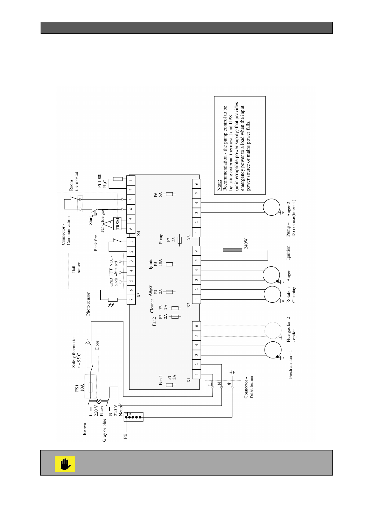
INSTALLATION, OPERATION AND MAINTENANCE MANUAL
8. WIRING DIAGRAME OF THE BOILER WITH THE PELLET BURNER
Figure 19. Wiring diagrame of a boiler with Bisolid GP xx R tsc pellet burner
It is recommended the pump’s control to be made by using external thermostat
and UPS (uninterruptible power supply) that provides emergency power to a
load when the input power source or mains power fails.
Bisolid Automat OM-BAV05/02/2018/EN 57
Page 58
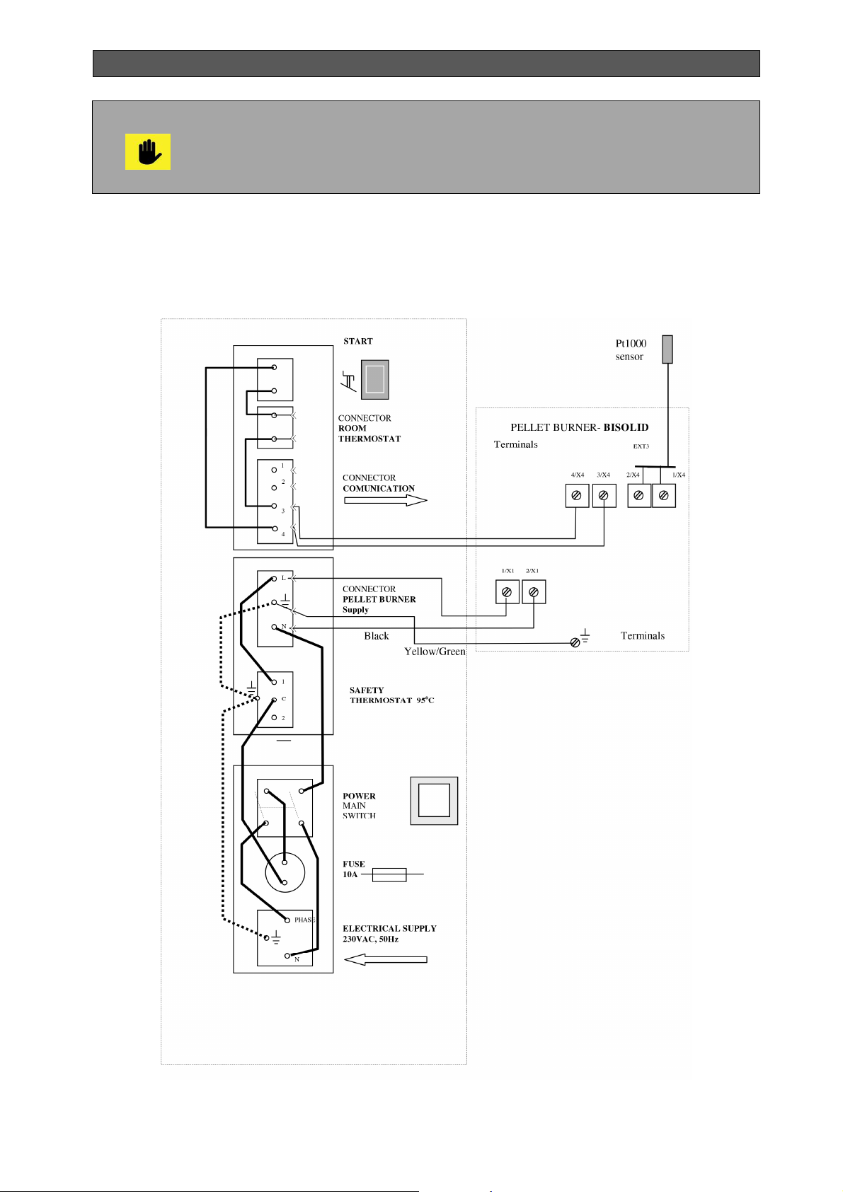
INSTALLATION, OPERATION AND MAINTENANCE MANUAL
When boiler operates with preferred fuel (wood pellets) or other suitable fuel
(firewood or wood chips) do not interrupting the power supply of the boiler, as
circulation pump should operates to cool the boiler. In all diagrams for
conection the circulation pump connection should operate whenever the boiler
gives heat transfer with the purpose of discharging.
8.1. PALLET BURNER CONNECTOR’S PANEL
Figure 20. Connector’s panel diagram for electrical connection of tube pube burner
Bisolid GP xx R tsc
Bisolid Automat OM-BAV05/02/2018/EN 58
Page 59
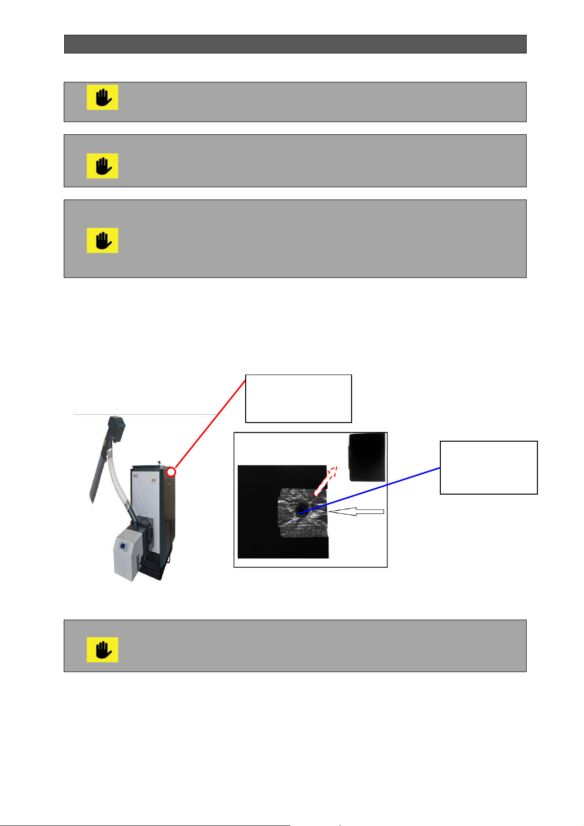
INSTALLATION, OPERATION AND MAINTENANCE MANUAL
All activities on the electrical installation of the burner, adjustments, where
covers and other items are removed that protect against contact with live parts,
should only be performed by a qualified person.
The burner should be connected to the electrical installation of the equipment
to which it is installed, complying with the safety rules. Use the power cable
and the attached diagram for connection to the supply voltage and to the
command module of the burner.
Connectinion of the room thermostat. It is possible to use room thermostat
ONLY in case of boiler operation with pellets. Before connecting the room
thermostat to the connector (moving part) for ROOM THERMOSTAT
(positioned on the back of the boiler’s side cover panel), remove the factory
installed bridge in the connector. Use only room thermostat contact without
external voltage! See electrical connections!
The installation of the socket, respectively the water temperature sensor Pt1000 is carried out
according to the diagram shown in Figure 21.
Figure 21. Installation of the water temperature sensor
Place for mounting
sensor Pt1000
Installation of the temperature sensor should be performed as shown on
the above presented diagram.
This is safety related operation and should be performed by a qualified
technical person!
Socket for
mounting sensor
Pt1000
Bisolid Automat OM-BAV05/02/2018/EN 59
Page 60

INSTALLATION, OPERATION AND MAINTENANCE MANUAL
9. BOILER INSTALLATION INSTRUCTIONS
9.1. BOILER INSTALLATION - GENERAL INFORMATION
Bisolid Automat series hot water boilers should only be installed by a specialized company
authorized for such activity. Boiler installation should be performed in compliance with the
preliminary designed project and the acting legal provisions.
The existing network of authorized service providers, which comply with these conditions, is
able to take responsibility for all boiler installations, their commissioning and warranty repairs.
Boiler installation should correspond to the acting prescriptions as well as to the operation and
installation manual. The manufacturer is not liable for damages caused as a result of
unqualified installation.
All problems (malfunctions) caused by boiler clogging with dirt from the
heating system and/or malfunctions caused by clogging are not covered by
boiler warranty card.
9.2. CHOOSING APPROPRIATE BOILER MODEL
The choice of an appropriate boiler model, i.e. its heating output is a main condition for the
economic and optimum operation of the equipment. The boiler should be chosen so that its
rated power corresponds to the heat losses of the site.
Choosing a boiler with too high heating output (oversize) leads to increased depositing of tar
and condensation. Therefore, it is not recommended to use boiler with higher power than the
heat losses of the site.
9.3. POSITIONING IN THE BOILER ROOM
Bisolid Automat series hot water boilers may be positioned in rooms that comply withl ocal
norms in effect. The boiler room should allow constant fresh air inflow, needed for the
combustion process. The air should be clean, free of halogenated hydrocarbons, corrosive
vapors and should not be too humid and dusty. The room should be protected against freezing
and air relative humidity should not exceed 80%.
When installing the boiler, for easy manipulation, it is necessary to pay attention to the
following (Figure 22):
The minimum distance in front of the boiler should be 1000 mm to allow servicing the
pellet tube burner and to remove and put back the ashtray.
The minimum allowed distance between the rear part of the boiler (where the boiler
connects to the chimney) and a wall should not be less than 500 mm.
The minimum distance between the left and right side of the equipment and a wall
should be 400 mm to ensure free access to service the equipment.
The minimum distance of the free space above the boiler should be at least 1200 mm
to ensure easy access to the fuel hopper when loading the fuel and to allow for
cleaning the accumulated ash on the heat exchanger.
The minimum allowed distance between the outer parts of the boiler and the flue pipe
to flammable materials should be 200 mm.
A safe distance of 300 mm should be observed in cases the degree of flammability of
the material is unknown. The safety distance should be respected when deploying
household objects, flammable materials and fuels in the boiler room.
Bisolid Automat OM-BAV05/02/2018/EN 60
Page 61
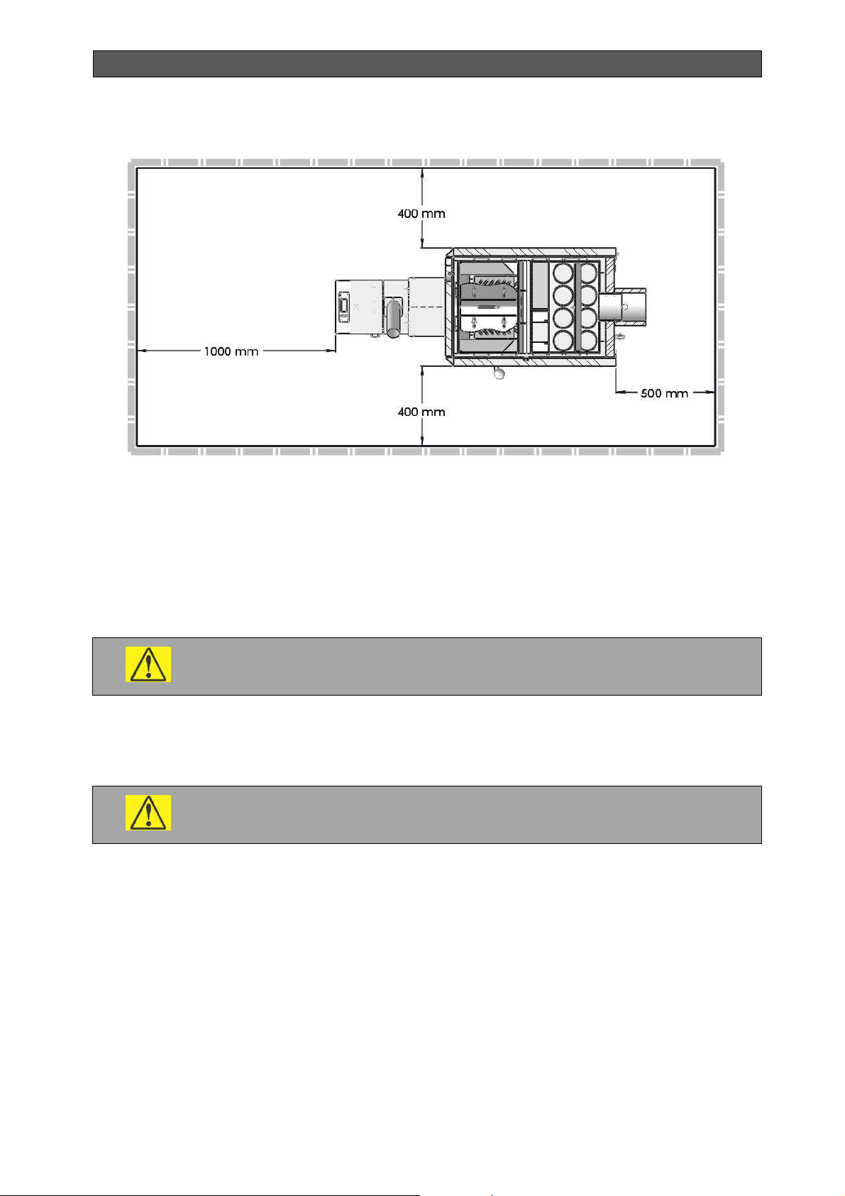
INSTALLATION, OPERATION AND MAINTENANCE MANUAL
Figure 22. Positioning in the boiler room
The boiler should be steadily fixed over inflammable or heat-insulated foundation, which
should exceed the boiler contour with minimum of 300 mm in front and 100 mm in all other
sides. For easy service it is recommended that the boiler is positioned on an inflammable
foundation 100 - 150 mm high.
The boiler room should ensure constant combustion air flow. Air consumption depends on the
power of the boiler, respectively 45 – 60 m3/h (the corresponding air opening to allow air flow
is 200-300 cm2).
When the boiler operates do not touch any hot water connections or the
flue pipe.
If there are two boilers in the room, it is not allowed to position any fuel between them. It is
recommended to keep minimum distance of 800 mm between the boiler and the fuel, or to
store the fuel in a premise different from the boiler room.
Do not put flammable materials on the top of the boiler or near it within the
safety distance.
9.4. WATER SUPPLY REQUIREMENTS
Bisolid Automat boiler is designed for systems with independent or forced water circulation. To
limit flue gas condensation and to increase the lifetime of the boiler at the same time, it is
recommended to use devices that do not allow lowering the temperature below 65 °C (flue gas
condensation point). For this purpose, for example, a three-way or eventually a four-way
mixing valve can be used, or a thermostatic valve.
Clean water should be used as a heat carrier, corresponding to the requirements of the
standards. The hardness of the boiler water should not exceed the values of the
recommended parameters (Table 18).
Bisolid Automat OM-BAV05/02/2018/EN 61
Page 62
INSTALLATION, OPERATION AND MAINTENANCE MANUAL
Table 18. Boiler water parameters
Parameter
Hardness mmol/l 1
Ca2+ mmol/l 0.3
Total concentration of Fe + Mn mg/l (0.3)*
* - recommended value
Liquid with low freezing point and anti-corrosion effect can be used as passive protection of
the boiler. In the event, a two-way safety valve is connected to the system, the application of
anti-freezing liquid is not recommended.
Measurement
Unit
Value
9.5. CONNETING THE BOILER TO THE HEATING SYSTEM
9.5.1. BOILER EXCESS HEAT RELEASE
The cooling loop is designed to release excess heat from the boiler to avoid exceeding the
maximum allowed boiler water temperature of 95 °C. Connecting the cooling loop to the boiler
flanges is shown in Figure 23 and to the two-way safety valve in Figure 25. In the event of
boiler overheat (the output water temperature exceeds 95°C), the thermostatic valve switches
on and the excess heat is being released by the cooling loop.
The two-way safety valve DBV 1 is used to release the excess heat in order to avoid
exceeding the maximum permissible temperature of the water in the boiler i.e above 95 °C. In
the event the system is equipped with a protective device against overheating, but
nevertheless the boiler overheats (the output water temperature is higher than 950С), the
protective device creates a cold water cycle, which remains active until the temperature
decreases below the limit value. At this point, the discharge cooling device and the cold water
running through the system close simultaneously.
Table 19. Two-way safety valve technical data
DBV 1 (Regulus)
Shutdown temperature °C 100 (+0-5°C)
Parameter Dimension Value
Maximum temperature °C 120
Boiler maximum pressure bar 4.0
Water maximum pressure bar 6.0
Nominal flow rate at ∆p 1bar m3/h 1.9
9.5.2. PURPOSE OF THE TWO-WAY SAFETY VALVE
It is imperative to install the two-way safety valve. The installation of the
two-way safety valve is performed by a qualified and competent specialist!
Bisolid Automat OM-BAV05/02/2018/EN 62
Page 63
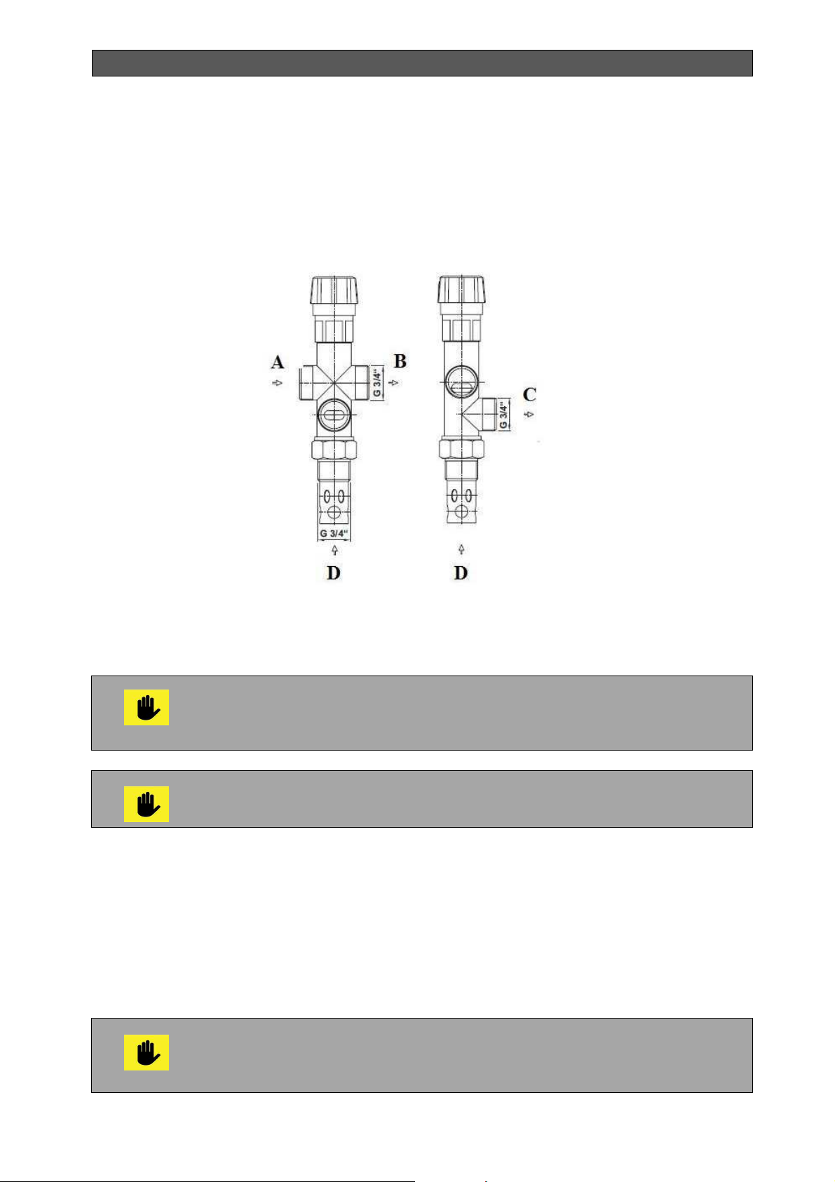
INSTALLATION, OPERATION AND MAINTENANCE MANUAL
The two-way safety valve DBV 1 is used for protecting boilers against overheats. Outlet and
inlet valves are integrated in the valve body operated by a thermostatic element. Upon
reaching the limit temperature, the outlet and inlet valves open simultaneously allowing for
cold water to start flowing into the boiler and hot water to start discharging out of the boiler.
Upon lowering the temperature to a level below the limit value, the outlet and inlet valves close
simultaneously.
Figure 23. Two-way safety valve DBV 1
A - Cold water inlet.
B - Outlet to the boiler.
In the event of activation of the two-way safety valve that might cause inflow
of water, not meeting the requirements set out in Table 18, the water in
the system should be treated as per the requirements. Furthermore,
the pressure in the heating system should be adjusted to the desired value.
C - Draining outlet - pipeline.
D - Inlet from the boiler.
The two-way safety valve does not replace the safety valve.
If the pressure in the water pipeline is higher than 6 bar, a reducing valve should be installed
on the cooling water inlet. It should also be installed when after an additional cooling the
pressure in the heating system is too high. In these cases, it is recommended that the
pressure of the reducing valve is adjusted at a value twice the value of the pressure necessary
for the heating system, and the minimum is 2 bar.
9.5.3. INSTALLATION OF THE TWO-WAY SAFETY VALVE
The installation of the two-way safety valve should be performed only by
a qualified person. For optimum operation of the thermostatic two-way safety
valve, it is necessary to comply with the prescribed conditions for installation
and to observe the flows direction indications marked on the valve body.
Bisolid Automat OM-BAV05/02/2018/EN 63
Page 64
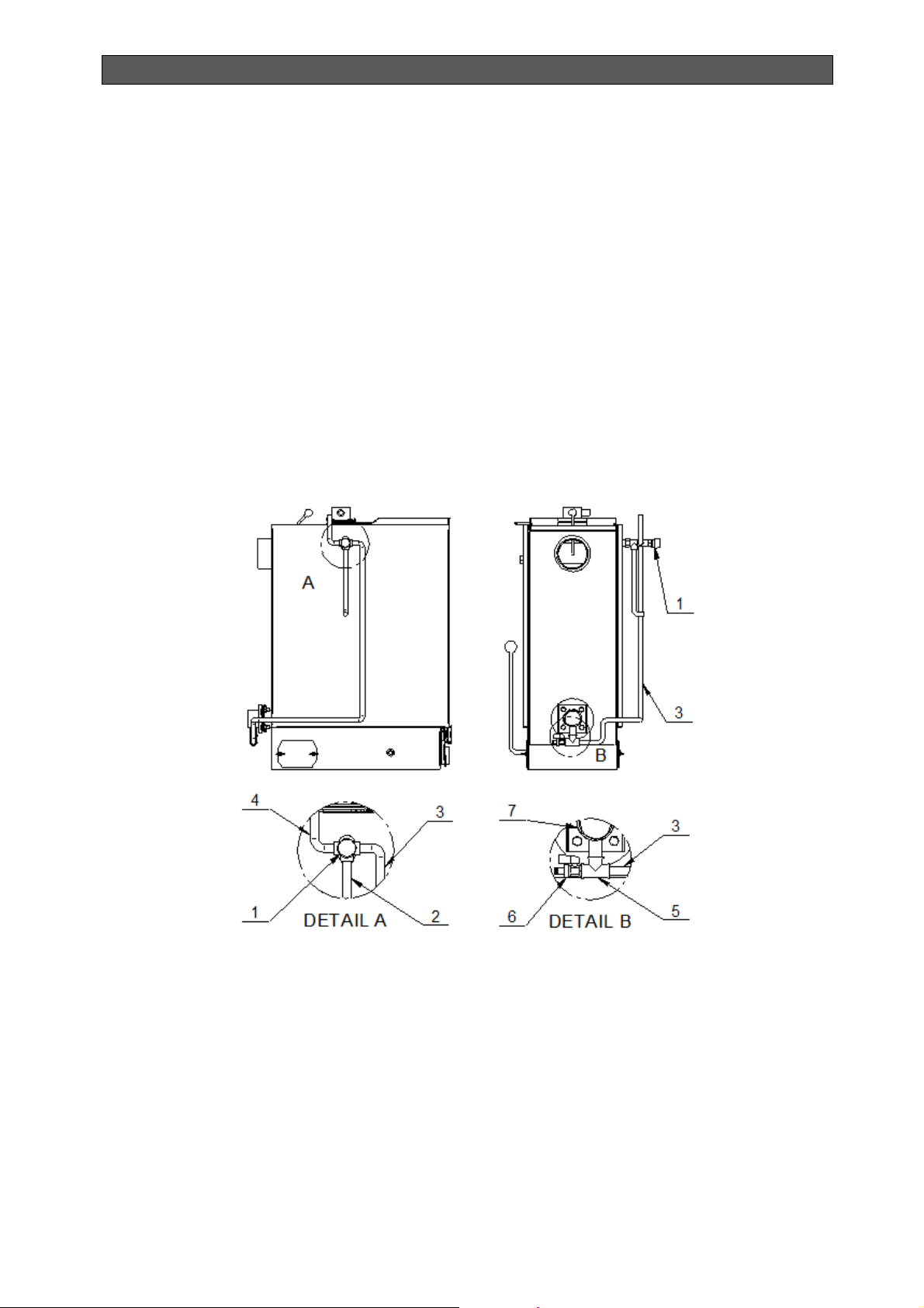
INSTALLATION, OPERATION AND MAINTENANCE MANUAL
The safety valve is always mounted directly on the boiler (in the upper left part of the boiler) or
to the outlet pipe. When installing the valve, it should be checked whether the use of a 3/4" tip,
which can be either in the pipeline or on the boiler, provides complete immersion of the valve
thermostatic element after installation of the valve.
After mounting the tip in position "C" (Figure 23), the draining pipeline, through which the
waste water along with the hot water outflow, is connected,
The cooling water supply is connected in position "A" (Figure 23) according to Figure 25,
which supplies the boiler with cooling water after commissioning the valve. Particulate filters
should be installed in the place from where the cooling water is supplied.
The pipeline, which according to Figure 25 joins the return pipeline of the heating system near
the boiler is connected in position "B" (Figure 25),
The valve should be installed to the boiler according to Figure 25 i.e. outlet "C" - the draining
pipeline outlet should be positioned downwards.
Figure 24. Connecting DBV 1 to Bisolid Automat Boilers
1. Two-way safety valve DBV 1
2. DBV 1 outlet - excess heat removal
3. Connecting pipeline - connecting DBV 1 to the boiler intake pipeline (boiler return
pipeline).
4. Intake pipeline for DBV 1 - cooling water supply.
5. T-shape part for connection of the connecting pipeline and the outlet valve.
6. Inlet and outlet valve
7. Boiler return pipeline
Bisolid Automat OM-BAV05/02/2018/EN 64
Page 65
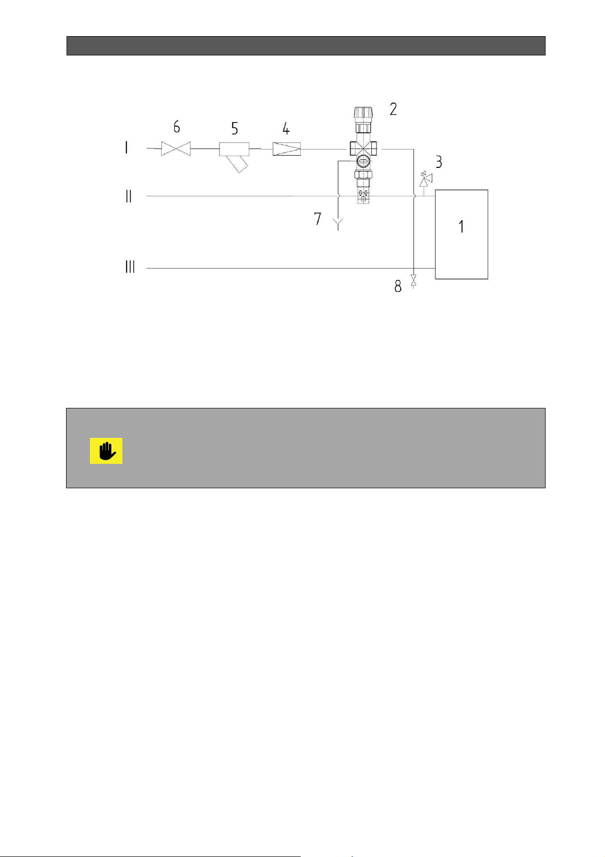
INSTALLATION, OPERATION AND MAINTENANCE MANUAL
Figure 25. Recommended diagram for connecting DBV1 two-way safety valves
1 – Boiler.
2 – DBV 1 valve.
3 – Safety valve.
4 – Reducing valve.
5 – Filter.
It is necessary to install a safety valve for maximum overpressure of 4 bar
on the system and its dimensions should comply to the rated power of the
boiler. The safety valve should be positioned directly behind the boiler. There
should not be any shut-off valve located between the safety valve and the
boiler. If you have any questions, please, contact an authorized installation and
service center.
6 – Ball valve.
7 –Outlet to the drain pipeline.
8 - Outlet valve.
I – Cold water inlet.
II – Heating water outlet.
III – Return water inlet.
9.5.4. TWO-WAY SAFETY VALVE PERIODIC MAINTENACE
A control checkup should be performed once a year by appropriate turning of the head of the
two-way safety valve to remove any impurities precipitated on the valve. It is also necessary to
clean the filter on the cooling water outlet.
9.6. BOILER CONNECTION TO THE SMOKE EXTRACTOR
The smoke extractor is fixed to the chimney neck by 5 mm diameter rivets. The shortest
possible way should be chosen to connect the flue pipe from the boiler to the chimney at an
angle and upwards.
The smoke extractor should be brought to the chimney and should be fixed to the chimney
neck not to allow any accidental or arbitrary movement. The smoke extractor should not be
longer than 1.5 m and if conditions allow, additional elbows should not be used. All smoke
Bisolid Automat OM-BAV05/02/2018/EN 65
Page 66

INSTALLATION, OPERATION AND MAINTENANCE MANUAL
extractor components should be made of non-combustible materials. Flue pipes for solid fuels
are very well adjusted pipes, which are installed in the same direction as the flue gases.
9.7. BOILER CONNECTION TO THE CHIMNEY
Bisolid Automat series boilers in central heating systems should be connected mandatory to a
separate chimney with appropriate chimney draft, which is a main precondition for optimum
operation of the boiler.
The chimney draft affects boiler thermal power, its performance and lifetime. The chimney
draft depends on chimney cross-section, height and roughness of the inner wall, and
furthermore on the difference between the flue gas temperature and the outside temperature.
The most suitable chimneys are the insulated chimneys and those with a chimney insert. The
actual draft can be measured by an authorized installation and service company using a
special gas analyzer.
The smoke extractor between the boiler and chimney should be insulated with mineral glass
wool. The smoke extractor and chimney must be made of steel or equivalent material that can
be used at temperatures around 400 °C.
All system connections for the flue gases must be solid and reliable to perform better
combustion and achieve high efficiency. The smoke extractor need to be connected to the
chimney using the shortest way and in the amounts indicated in Figure 26. The horizontal links
and elements that increase the pressure loss such as elbows should be avoided. Should not
be used as a single vertical stack steel tube. The chimney must be made of an inner and an
outer surface. The outer surface can be made of steel or brick. On the inner surface of
chimneys is recommend to use elements of stainless steel to prevent corrosion. The space
between the inner and outer surfaces of the chimney should be insulated to prevent
condensation of the flue gases.
At the lowest level of the chimney, there must be a hole with lid for cleaning, which is
necessary to be made of steel.
These dimensions in Figure 26 are indicative only. The working
installation depends on the diameter, height, roughness of the wall of the
chimney, temperature difference between the combustion products and the
external air temperature. We recommend using of a chimney built-in metal
insert.
Bisolid Automat OM-BAV05/02/2018/EN 66
Page 67
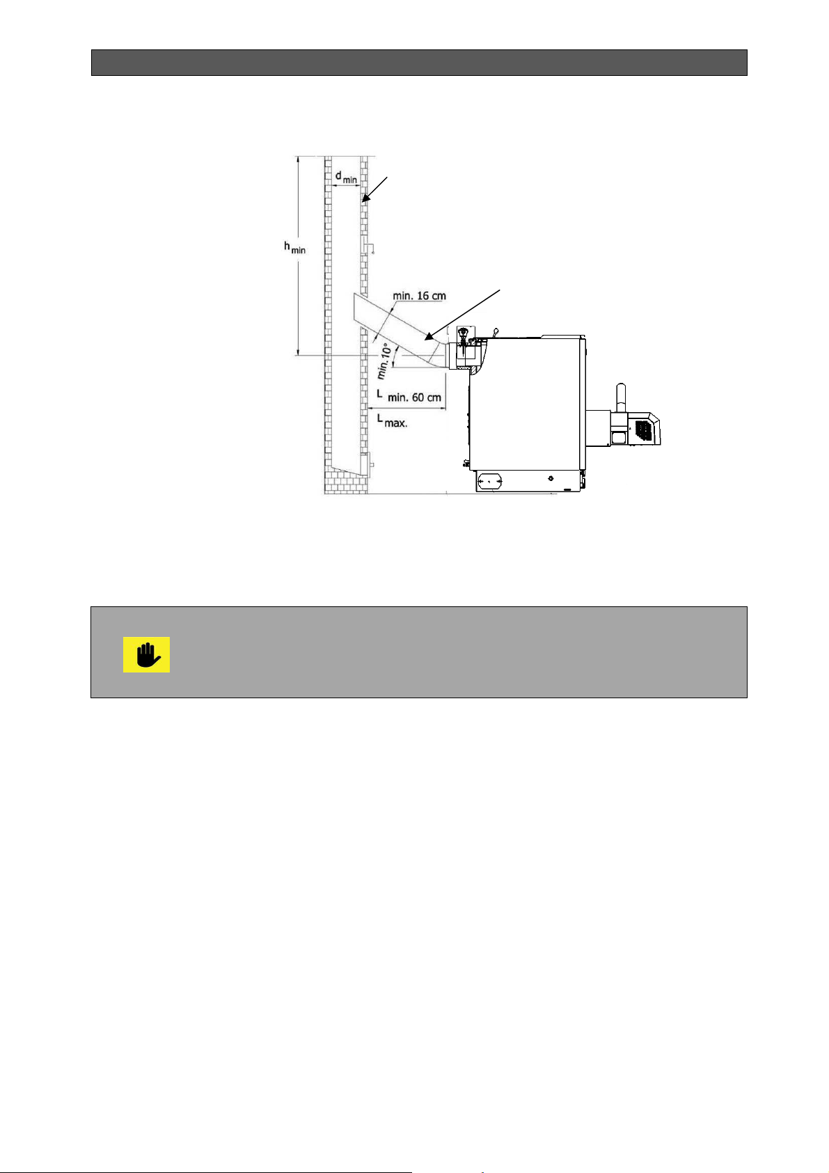
INSTALLATION, OPERATION AND MAINTENANCE MANUAL
inspection
Figure 26. Recommended chimney system dimensions
Chimney
Draft limiter
Smoke extractor
A hole with
lid for
The dimensions of the smoke extractor and the chimney must not be smaller than the chimney
neck dimension from the boiler. The diagram in Figure 27 is recommended for dimensioning of
the total height and minimum inner diameter of the chimney, depending on the boiler heat
output if it is not explicitly stated in the mandatory local regulations.
If the chimney draft is insufficient or chimney is not built according to the project
(bad condition of the structure, without insulation, blocked etc.) can occur big
problems in combustion. In this case, we strictly recommend the chimeny
condition to be controlled by the technician who will identify and remedy any
irregularities.
Bisolid Automat OM-BAV05/02/2018/EN 67
Page 68
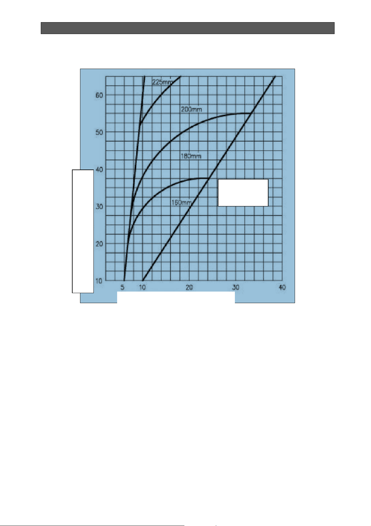
INSTALLATION, OPERATION AND MAINTENANCE MANUAL
Figure 27. Diagram for dimensioning of the total length and minimal diameter of the chimney
Inner diameter
of the chimney
Boiler heating output, kW
Height of the chimney, m
Above the roof of the building, the highest level of a chimney should be in accordance with the
dimensions specified in Figure 28. The construction of the exterior of the chimney must be so
as to reduce the harmful effects of fumes in the air and improve the chimney draft.
Bisolid Automat OM-BAV05/02/2018/EN 68
Page 69
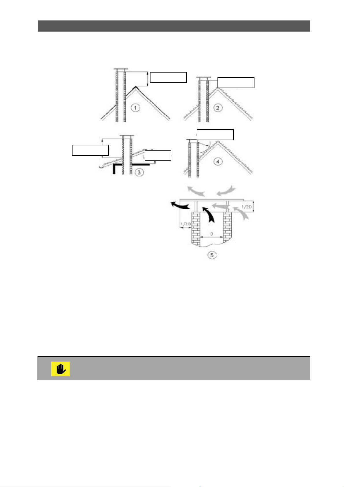
INSTALLATION, OPERATION AND MAINTENANCE MANUAL
min. 0.4m
min. 0.8m
min. 1.0m
< 20o
min. 1.0m
Figure 28. Requirements for the chimney construction above the roof
9.8. TRANSPORTATION AND STORAGE
Upon dispatch, the manufacturer offers the boilers mounted on wooden pallets and fixed
against displacement with screws. The boilers should not be transported in position different
from their normal operating position.
It is necessary to provide at least normal storage conditions for boilers during their storage and
transportation.
Do not apply pressure on the boiler packaging and covers during storage and transportation.
Boilers should not be carried or transported without the use of forklift trucks,
trolleys or other wheeled vehicles for transportation.
Packaging is disposed of in one of the secondary raw materials centers or in the municipal
landfill.
The disposal of the product (the boiler) after expiration of its lifetime is done in one of the
secondary raw materials centers or in the municipal waste landfill.
Bisolid Automat OM-BAV05/02/2018/EN 69
Page 70

INSTALLATION, OPERATION AND MAINTENANCE MANUAL
Bisolid Automat OM-BAV05/02/2018/EN 70
Page 71

INSTALLATION, OPERATION AND MAINTENANCE MANUAL
10. TROUBLESHOOTING
10.1. BOILER TROUBLESHOOTING
Failure
The boiler can not reach
its rated power
Boiler power can not be
regulated
High water temperature in
the boiler and low water
temperature in the
radiators. Water in the
boiler boils.
Unsealed soot door Fasten all ash door nuts, if necessary
Unsealed heat-exchanger cover
and fuel feeding door
Insufficient chimney draft. Perform chimney draft checks and take
Used fuel is with low calorific value. Use the prescribed fuel type with
Caused by improper pellet burner
operation
Unsealed fuel feeding and ash
cleaning doors
Too high chimney draft Half-close the valve in the chimney
High hydraulic resistance of the
heating system, especially in the
standalone system.
Too high chimney draft Reduce chimney draft by using a
Reason
Solution
replace door sealing
Check sealing ropes, correct sealing
ropes positioning, if necessary replace
sealing ropes.
corrective measures.
appropriate calorific value, especially in
low outside temperatures.
Refer to the section on description,
commissioning and operation of tube
pellet burner series Bisolid GP xx_B
thc.
Check sealing ropes, correct sealing
ropes positioning, if necessary replace
sealing ropes.
pipe, if necessary perform chimney
draft checks and take corrective
measures.
Perform system cleaning with rinse, if
necessary install circulation pump.
chimney damper.
Bisolid Automat OM-BAV05/02/2018/EN 71
Page 72

INSTALLATION, OPERATION AND MAINTENANCE MANUAL
10.2. PELLET BURNER TROUBLESHOOTING
Failure Reason Solution
The burner is installed
on a heating boiler, but
the temperature in the
heated rooms is low.
The burner is installed
on a heating boiler, and
the temperature in the
heated rooms is high.
The burner is switched
on, but there is no
combustion process.
Difficult fuel ignition. Low quality wood pallets Their humidity is probably higher than
The fuel ignition is
accompanied by strange
noises.
Overheating of the boiler
to which the burner is
installed
Fuel does not ignite. No wood pellets in the fuel hopper. The fuel hopper, from which the burner
Insufficient thermal power. It is necessary to increase thermal
power rate of the burner.
Low water temperature setup. It is necessary to increase the value of
the water temperature setup.
It is also necessary to check the
circulation water temperature setup,
adjusted in the burner controller
Low setup temperature of the
room thermostat (if connected).
Thermal power, exceeding the
consumption
High adjusted temperature It is necessary to decrease the setup
High setup temperature of the
room thermostat (if connected).
There is no operation setup. Check the operation setup from the
Insufficient chimney draft. It is necessary to check the condition
Lack of heat load or incorrect
adjustment of the thermal power of
the burner or the boiler.
Missing or failure of the two-way
safety valve.
No fuel in the burner combustion
chamber.
Presence of fuel on the burner
grate, but it is not fired or it has
burned out and there is no
combustion process
It is necessary to increase the
temperature setup of the room
thermostat.
It is necessary to reduce the burner’s
thermal power rate.
value (recommended minimum is up to
60oC) or the circulation water
temperature setup, defined in the
controller.
It is necessary to decrease the setup
temperature of the room thermostat.
burner control module
the normal needed for the burner
operation, it is necessary to change
the pellets.
of the chimney and the equipment to
which the burner is installed and to
clean the ash deposits. Even after
cleaning, it may be needed to adjust
the system operating parameters – ask
for assistance a service provider.
It is necessary to check the proper
operation of the boiler-burner system
and to adjust eventually the operating
parameters - to be performed by a
specialist. After boiler cool-down and
failure removal, the emergency
thermostat has to be deactivated
(unscrew protective cap, press the
button and screw the cap back), start
the burner by restarting it.
auger transports the fuel, must be
loaded.
The process of initial firing can be
renewed by restarting the burner
Clean the fuel gathered on the burner
grate.
If the ignition heating element is out of
order or inactive, then it must be
replaced
Bisolid Automat OM-BAV05/02/2018/EN 72
Page 73

INSTALLATION, OPERATION AND MAINTENANCE MANUAL
To be performed by service
The burner does not
start or stop operation.
The flame of the
combustion process is
"cloudy" and chimney
smokes.
Burner starts, but can
not enter the set mode
Incorrect operation of the photosensor used for monitoring the
combustion process.
No power supply. Check whether the burner display and
No start signal to the burner. Check whether the burner has
The burner is not working,
although there is an operation
signal.
Blown fuses.
Low quality wood pallets The humidity is probably higher than
Inappropriate adjustment of the
burner parameters
Incorrectly positioned photosensor.
The photo-sensor surface is dirty. Clean the dirt carefully.
The photo-sensor used for monitoring
the combustion process should be
adjusted or replaced – to be performed
by a service specialist only.
its indication operate.
Check working order of the power
supply of the equipment to which the
burner is installed and which provides
voltage with parameters 220 VAC, 50
Hz – to be performed by a service
technician.
Check burner proper wiring according
to the presented electrical diagram.
Check for loose electrical connections
– to be performed by service
technician.
received start signal and whether the
electric circuits of the module,
providing signal for operation to the
burner are in good order - to be
performed by a service technician.
Check for loose connections. Check
the working order of the burner
operation control module, which
provides voltage and necessary
signals.
Check for activated emergency alarm
– check the list with alarm modes and
indications of the controller, presented
in the next table.
technician: check the fuses condition
and if there is need for replacement,
change the fuses with new with
corresponding parameters (Caution:
the fuses are fast-reacting)
the normal needed for the burner
operation, it is necessary to change
the pellets.
Adjustment of the equipment operating
parameters is needed – to be
performed by a specialist
Change the position of the photo-
sensor for monitoring the combustion
process, by rotating it around its
longitudinal axis.
Unstable operation of
the burner.
Bisolid Automat OM-BAV05/02/2018/EN 73
The photo-sensor is damaged –
there are burnout traces on its
surface.
Photo-sensor failure. Check photo-sensor working order.
Controller operation settings are
changed.
It is necessary to replace the photo-
sensor with new one – ask for service
assistance.
Reason – improper burner shut down.
Check the burner thermal power rate
setting.
Check the controller settings – to be
performed by a service technician
Page 74

INSTALLATION, OPERATION AND MAINTENANCE MANUAL
Excess heating of the
pellet feeding pipe.
Heating the pellet
feeding pipe and
emergency thermostat
activation
Polluted and/or melted
photo-sensor.
Presence of unburned
fuel over the combustion
chamber grate.
Slag deposits on the
combustion chamber
grate.
Error message,
displayed on the
controller display
The burner has stopped,
but after new start it
operates.
High temperature of the
flue gases (if a
thermometer is installed)
Smoke in the boiler
room after a certain
period of operation
Failure of the burner
cleaning device.
Other failures not
described above
In all other cases, the repair of any failure and damage should be performed by the
manufacturer or an authorized service provider.
An obligatory condition for the normal operation is the presence of pellets, as
main fuel. Loading wood chips, as other suitable fuel to be made in operating
burner at steady state (presence of stable flame). Loading of firewood can be
made as in already operated burner, and in the absence of equipment start.
The requirement for the second case is loading with wood to be realized in the
way to is not to close burner tubus, i.e. to provide normal flame output. There is
possibility to realized start delay of the equipment – the preliminary loaded
boiler with wood is automatically ignites by external start (for example GSM) or
with или by simply pressing of the switch START. This is significant advantage
if this facility – automatic ignition of the other suitable fuel (even wood with high
moisture, difficult to burn in, hard flammable at normal boiler). The other
suitable fuel loading is made in open flue gases flap to the chimney with
purpose to limit smoke forming at the cover opening for loading.
Insufficient chimney draft or
contaminated equipment.
Low chimney draft or
contaminated with ash particles
equipment.
Improper shut down of the burner Clean the photo-sensor surface or
Inefficient fuel combustion. Adjust operation parameters of the
Fuel used is with high ash content
and does not comply with the
equipment requirements.
Burner operation mode exceeding
the rated thermal power.
Problem in the burner operation. It is possible to seek consultation /
The photo-sensor sends wrong
information to the controller.
Dirty heat-exchanging surfaces
depending on the equipment type
and operation mode.
Dirty or clogged with ash flue line
for extracting the flue gases from
the heat consuming equipment.
The cleaning cannot be done
properly
Competent consultation and / or
Clean the equipment and the chimney,
if necessary. Possible solution is to
install additional flue gas fan and/or
change the chimney.
Clean the equipment and the chimney
if necessary. Restart the burner
Possible solution is to install additional
flue gas fan and/or change the
chimney line.
replace it withnew one. Observe the
burner shut down procedure,
presented in the manual.
equipment - adjustment is needed
and/or consultation with an authorized
technician.
Change the fuel with a new one
complying with the requirements for
reliable operation of the burner.
Reduce the burner thermal power by
changing its thermal power rate.
intervention by a service technician
Check the amount of the fuel on the
grate. Seek assistance by a service
technician for consultation or
adjustment.
Clean the heat-exchanging surfaces of
theequipment.
Clean the heat consuming equipment
from the ash deposits.
Competent consultation and / or
intervention by a service technician is
needed.
intervention by a service technician is
needed.
Bisolid Automat OM-BAV05/02/2018/EN 74
Page 75

INSTALLATION, OPERATION AND MAINTENANCE MANUAL
Bisolid Automat OM-BAV05/02/2018/EN 75
Page 76

INSTALLATION, OPERATION AND MAINTENANCE MANUAL
Supplier:
Address:
city of
Str.
Tel.:
Fax:
http://
We reserve the right to make technical changes!
Bisolid Automat OM-BAV05/02/2018/EN 76
 Loading...