

Page 1
ABM Food Former
NSF MODELS
F2000N – F3000N - F4000N - B1200N – HD3000N
OPERATION, SERVICE MANUAL &
PARTS LIST
* IMPORTANT SAFETY NOTICE *
This Manual contains important safety instructi ons
which must be strictly followed when using this equipment.
Item No. #356-8-13-4
REVISED JULY 23, 2014
Page 2

TABLE OF CONTENTS
INTRODUCTION Page
Warranty…………………………………………………………. 3
Reliability………………………………………………………… 3
GENERAL TECHNICAL FEATURES
Description……………………………………………………….. 4
Main features…………………………………………………….. 4
Safety devices……………………………………………………. 5
Components description…………………………………………. 5
Overall measurements…………………………………………… 6
INSTALLATION
Packing check……………………………………………………. 6
Placing the machine……………………………………………… 6
Electrical connections……………………………………………. 6
Control panel…………………………………………………….. 7
Operating test……………………………………………………. 7
UTILITY
Loading the automatic paper attachment………………………… 8
Product thickness regulation……………………………………… 9
Loading the product and use……………………………………… 10
CLEANING AND HYGIENE
Complete cleaning………………………………………………… 11
Disassembly of the removable accessories………………………... 11
Disassembly of the paddle………………………………………… 11
Disassembly of the hopper………………………………………… 11
Disassembly of the conveyor belt…………………………………. 11
Disassembly of the regulation drum………………………………. 12
Disassembly of the scraper………………………………………… 12
Cleaning of the disassembled components………………………… 12
Assembly of the accessories……………………………………….. 12
MAINTENANCE
Ordinary maintenance……………………………………………… 12
WIRING DIAGRAMS & SPARE PARTS
Wiring diagrams…………………………………………………… 13
Spare Parts…………………………………………………………. 16
2
Page 3

WARRANTY
The installation, the starting, and the operating of the machine must be performed by
skilled personnel only, who knows the machine. The personnel assigned to the assistance
and maintenance must always follow the instructions contained in the manual. The food
forming machine must be used by trained personnel only. If necessary provide for the
personnel’s training, to learn the usual operations in order to assure the correct use of the
machine.
ABM disclaims all responsibility in case of:
• Assembly of the components of the machine and the electric connection not
effected according to the established rules;
• Improper use of the machine;
• Tampering the controls or the security protection;
• Use of non-original spare parts;
The warranty does not cover the normal use of the parts.
RELIABILITY
In case of improper use of the machine, it is possible to have injuries and accidents.
The food forming machine must be used only by the personnel who must know the
machine and the content of the manual:
• Make sure that unskilled personnel – and especially children – do not operate the
machine;
• Do not modify or remove the safety devices (covers and protections), especially
those installed at the meat inlet;
• Never tamper with the electric system;
• Use the machine with concentration avoiding distractions;
• Before cleaning and maintenance, always disconnect the machine from the supply
system;
• Periodically check the main supply wire, in case of breaks or bad functioning,
provide for the replacement by skilled personnel.
• Never go near the machine with loose hair, clothes, bracelets, chains, rings, ties, etc.
to avoid the chance that they become tangled in the moving parts of the machine;
• Stop the machine whenever it makes strange noises during the functioning;
• Always keep the working area clean and dry;
• Do not deal with the repairs if you are not able to eliminate the possible breakdowns,
but contact the technical assistance;
• The machine is made of accessories and parts especially designed in order to reduce
the maintenance and minimum.
3
Page 4

GENERAL TECHNICAL FEATURES
Description
• The ABM Food Forming machine is characterized by:
• Compactness and small overall measurements and with special features, able to
satisfy the producing requirements of both the great and the small distribution;
• Reliability and safety in the operation and the cleaning processes;
• Hygiene of the parts in contact with the product through the use of innovative
materials conformed to the current regulations;
• Precision and compactness of the finished product;
• Strength, easy use, controls and working stationing especially designed to optimize
ergonomics.
Main Features
• The castings are made of anticorrodal thermically treated with innovative material
for food, while all the other components have been made of stainless steel. These
parts are particularly fit to resist the corrosive agents of the products used and are in
conformity with the hygienic regulations for food;
• The moving parts are started by an electronic motor and the movement transmission
operates through a chain and mechanism;
• The hopper, the paddle, the conveyor belt, the drum and the accessories are easily
disassembled to effect a regular cleaning.
• The thickness of the product is adjustable;
• The quantity of the hamburgers produced per hour can be varied on request in the
models with current continue motors;
• The hopper and the moving of the product operate in a continuous way and this
allows a homogenous dough;
• The controls are easily identifiable and suitable to prevent accidental starting;
• The transmission parts are located inside the crankcase;
• The machine is equipped with a device which allows the cleaning of the roll during
functioning (scraper) and permits the separation of the products;
• Different drums are available, suitable o the forming of products with different
shapes;
• On request, the machine can be supplied with electrical motors of different tensions.
4
Page 5
Safety Devices
The Food Forming Machine is equipped with the following protection and safety devices:
• Safety micromagnet on the hopper;
• Plastic cover servo-assisted by a micromagnet;
• Protection and front cover of the removable parts;
• Handle of the paddle optimized to avoid crushing and use of keys or particular tools;
• Starting of the machine through reverser for servo-assisted manual or automatic
control;
• Emergency button
• Materials in conformity with the food hygienic regulations and fit to guarantee the
good resistance to oxidation.
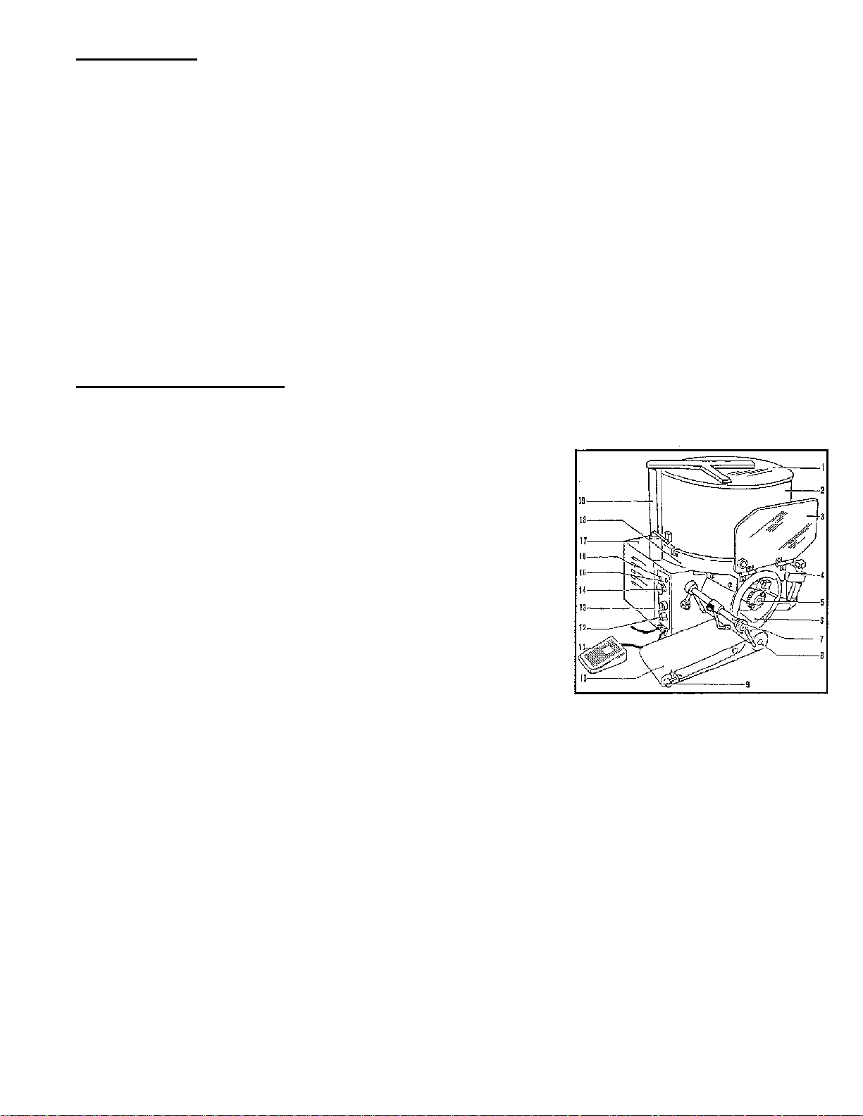
Components Description
CONTENTS
1. Cover
2. Hopper
3. Protection
4. Papering attachment
5. Drum stop ring nut
6. Drum
7. Scraper
8. Leading roll
9. Led roll
10. Conveyor belt
11. Footswitch
12. Speed variator for the mod. with current continuous
13. Manual/automatic switch
14. Stop button
15. Feeding signal light
16. Stop signal light
17. Transmission protection crankcase
18. Base
19. Cover shaft
5
Page 6
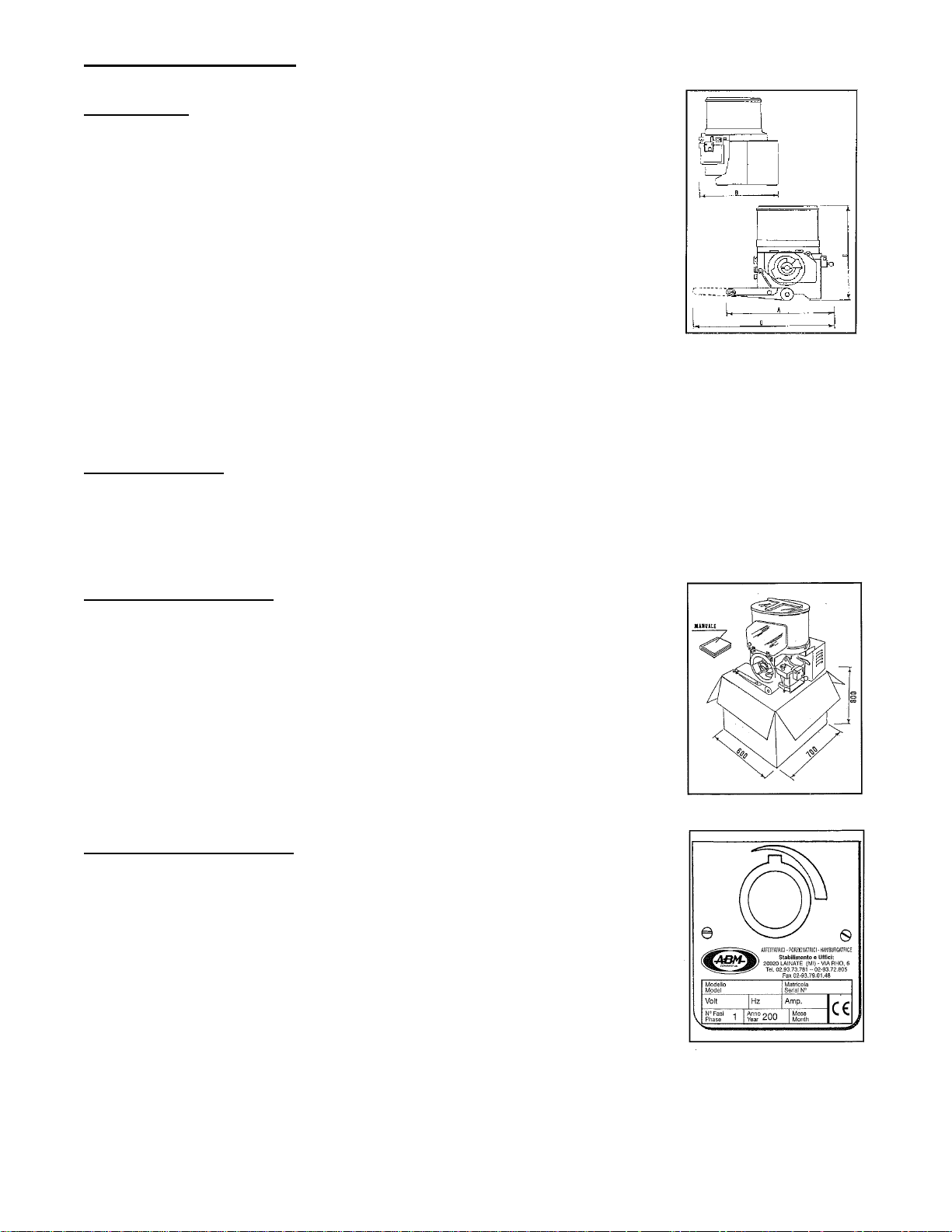
Overall Measurements
F2000/4000
Length (A) 620
Width (B) 500
Height (C) 610
Gross Created Weight – 72 kg.
Net Uncrated Weight – 67 kg.
Hopper capacity – 20 kg.
Optional Conveyor Belt – 1850 x 145
Hopper Power – see identification tag
Motor Power – see identification tag
INSTALLATION
Packing Check
• At the receipt of the machine, check the package to verify that the machine has not
been damaged.
The components of the package can be assimilated to the urban solid rubbish.
Placing the Machine
• It is advisable to place the Food Forming Machine
on a stable working table positioned on a height of
about 800mm from the ground.
• The installation area must allow the use of the machine
in an optimal and ergonomic way. It is advisable to
place it in a dry, breezy place, far from warmth sources;
it can be used without any special arrangement of a
normal working place.
Electrical Connections
• The machine is equipped with a feeding wire. Before
connecting it to the socket, verify the functioning tension
showed on the identification tag.
• In case the details do not correspond, contact the
distributor for the assistance service.
• The socket for the connection must correspond to
the current rules.
6
Page 7
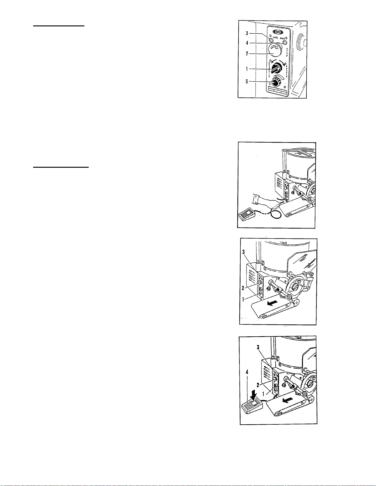
Control Panel
• Starting switch (automatic/manual) (1)
• Red stop button (2)
• Machine operating signal lamp (3)
• Machine stop signal lamp (4)
• Handle for speed regulation (5)
(only for model at variable speed)
Note – in the Model F4000 the regulation of the speed and the quantity of hamburgers
is made by rotating the regulating handle with a quantity of products variable from… to a
maximum of 4000 pieces per hour.
Operating Test
• Before controlling the operation, if you
have not already done, you must assemble
the hopper, assemble the conveyor belt,
close the cover and the front protection.
• Connect the footswitch, inserting the control
pipe into the bush on the control panel side.
• Connect the plug to the socket.
• Position the switch handle (1) on automatic.
• Verify the rotation of the drum and the
conveyor belt (see the arrow).
• Verify the lighting of the light.
• Push the stop button (2), the machine must
stop and the light (3) must light up.
• Position the switch handle (1) on manual.
• Press the footswitch.
• Verify the rotation of the drum and the
conveyor belt (see the arrow).
• Verify the lighting of the light.
• Push the stop button (2). The machine must stop
and the light (3) must light up.
7
Page 8
• During the operation, when lifting the front
drum protection, the machine must stop.
• To continue, close drum protection,
turn the operating switch again.
• During the operation, when rotating the
hopper cover, the machine must stop.
• To continue, close hopper cover,
turn the operating switch again.
UTILITY
To obtain good results you must use fitted meats and doughs. Arrange the machine with
all the accessories disassembled.
It is advisable not to use and let the machine function without any product in the
hopper.
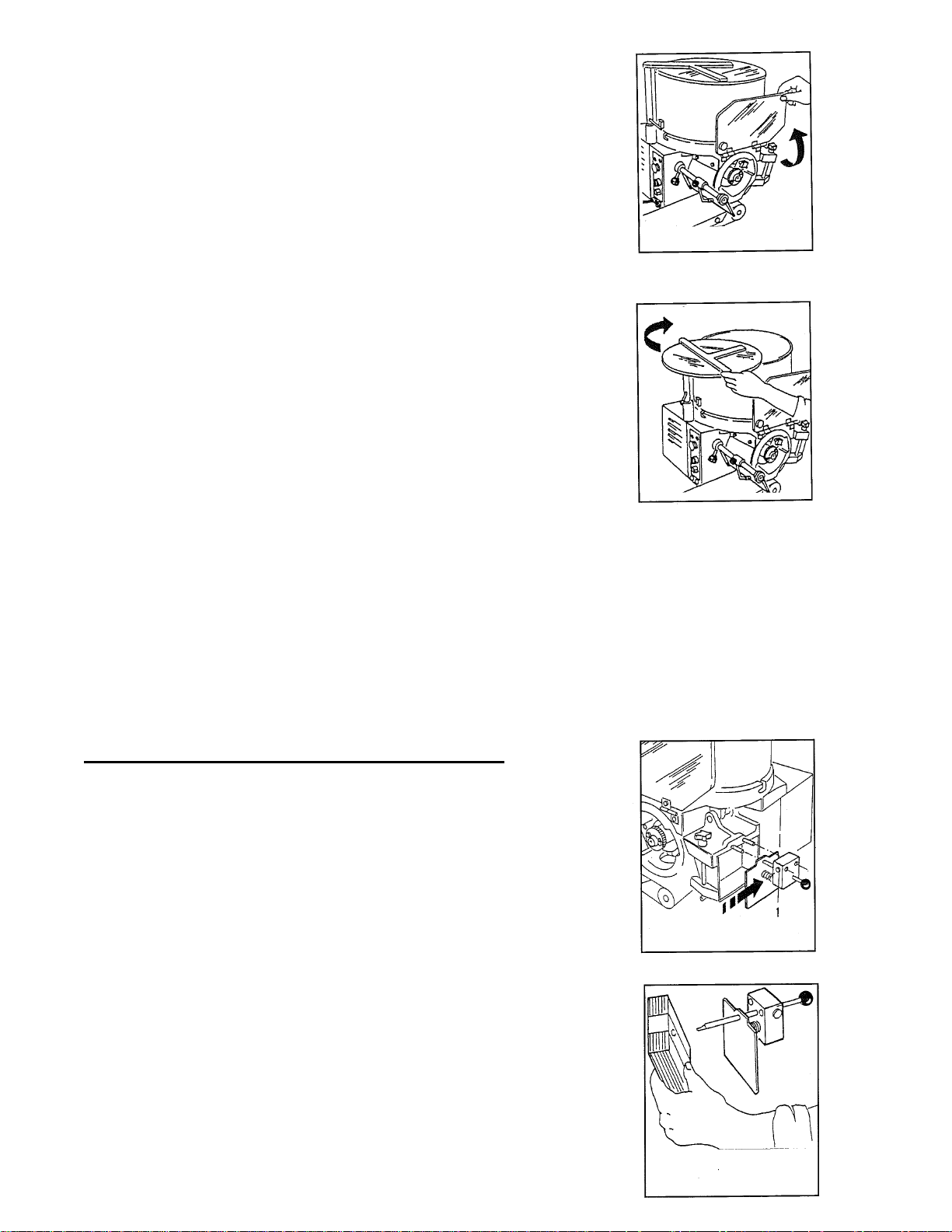
Loading the Automatic Papering Attachment
• Take out the papering attachment by pushing
the button (I) and slipping it off from the guide pins.
• Replace the pushing spring.
• Insert the paper block and take away the wrapper.
8
Page 9
• Reassemble the papering attachment in the guide pins,
until the stop click.
• Release the spring using the button placed under
the papering attachment (2).
• Position the papering attachment, freeing the
locking lever (2).
• Regulate the center of the paper, turning the
centering knob (4).
Before cleaning the machine, always make sure that the machine
Is stopped and disconnected from main supply.
Never use high pressure sprays during cleaning.
Never use solvents, thin ners , alcohol, etc. during cleaning.
Only use lukewarm water and some neutral detergent.
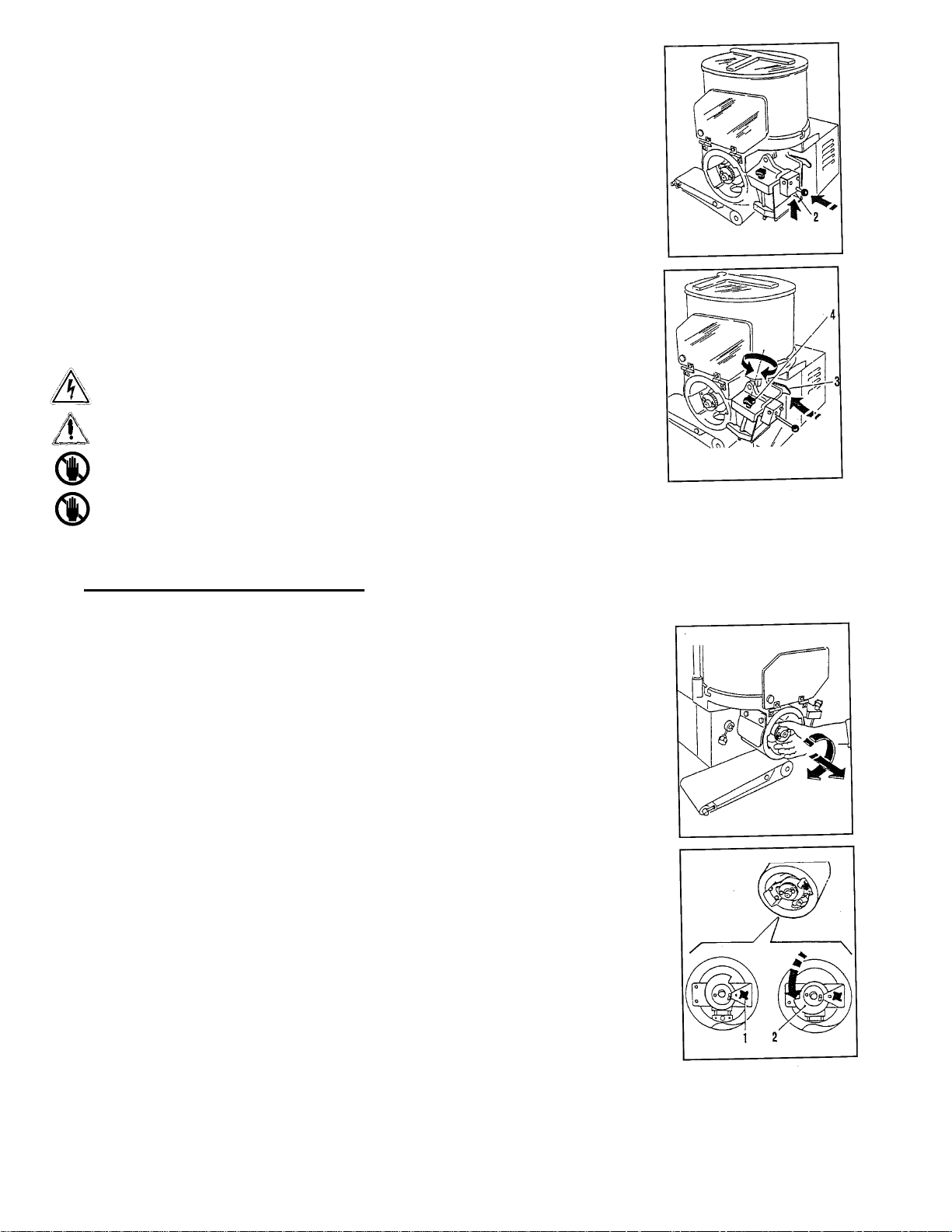
Product Thickness Regulation
The machine is regulated in the factory with a medium thickness; to obtain another
thickness, follow the instructions indicated below:
• Take out the regulation drum by operating on the
ring nut clockwise and taking out the drum.
• Loosen the stop knob of the gauging device (I).
• Turn the gauging device, to regulate the thickness (2).
• Lock the stop knob (1).
• Reassemble the drum, inserting it in the guide shaft,
until the stop click.
9
Page 10
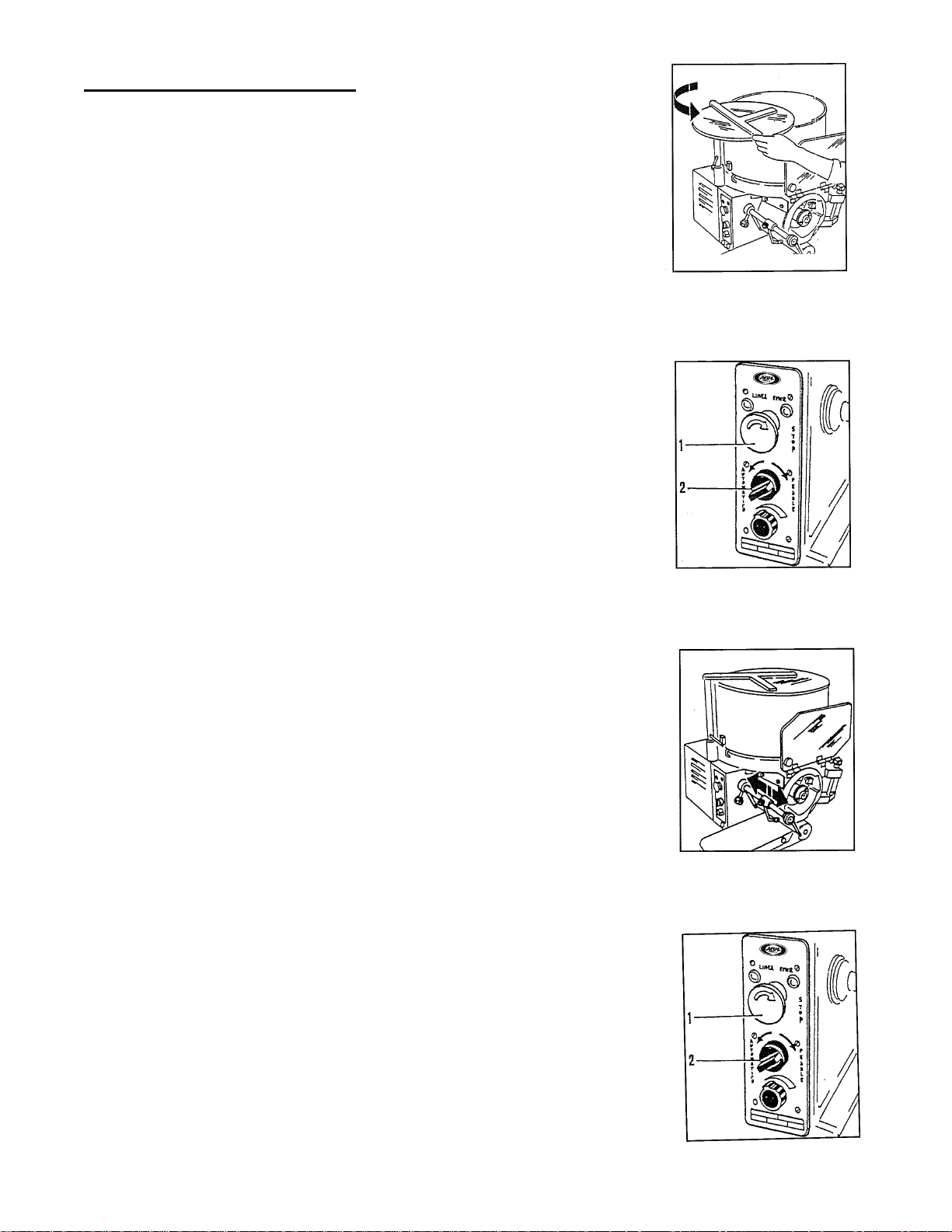
Loading the Product and Use
• Open the cover and load the product in the hopper
and close the cover again.
• Connect the plug to the socket.
• Start the machine: push the automatic switch (1).
• Regulate the production speed with the regulation handle (2)
(only for model with selector).
• During the operation, operate intermittently, in order
to clean the drum from residual product.
• The product will come down on the conveyor belt and
will be moved to its end.
• To stop the machine, operate on the stop button (I) or
open the protections.
• To continue, release the stop button and turn the start
switch again (2).
10
Page 11
CLEANING AND HYGIENE
Complete Cleaning
• It is advisable to clean the machine daily or if necessary more frequently, in case it
was very dirty or after long periods of inactivity.
• The cleaning must be carefully made for the parts in contact with the product.
• Clean the structure of the machine with soft cloths, sponges, and rinse with water
frequently. Finally dry with soft and dry cloths.
Attention: the machine is not protected against steam cleaners, high pressure power
washer, or similar systems. In this case there is risk of short circuit or serious damages to
the machine.
Disassembly of the Removable Accessories
• All the cleaning operations of the machine must always be done with the machine not
equipped with hopper, taking out the plug from the socket.
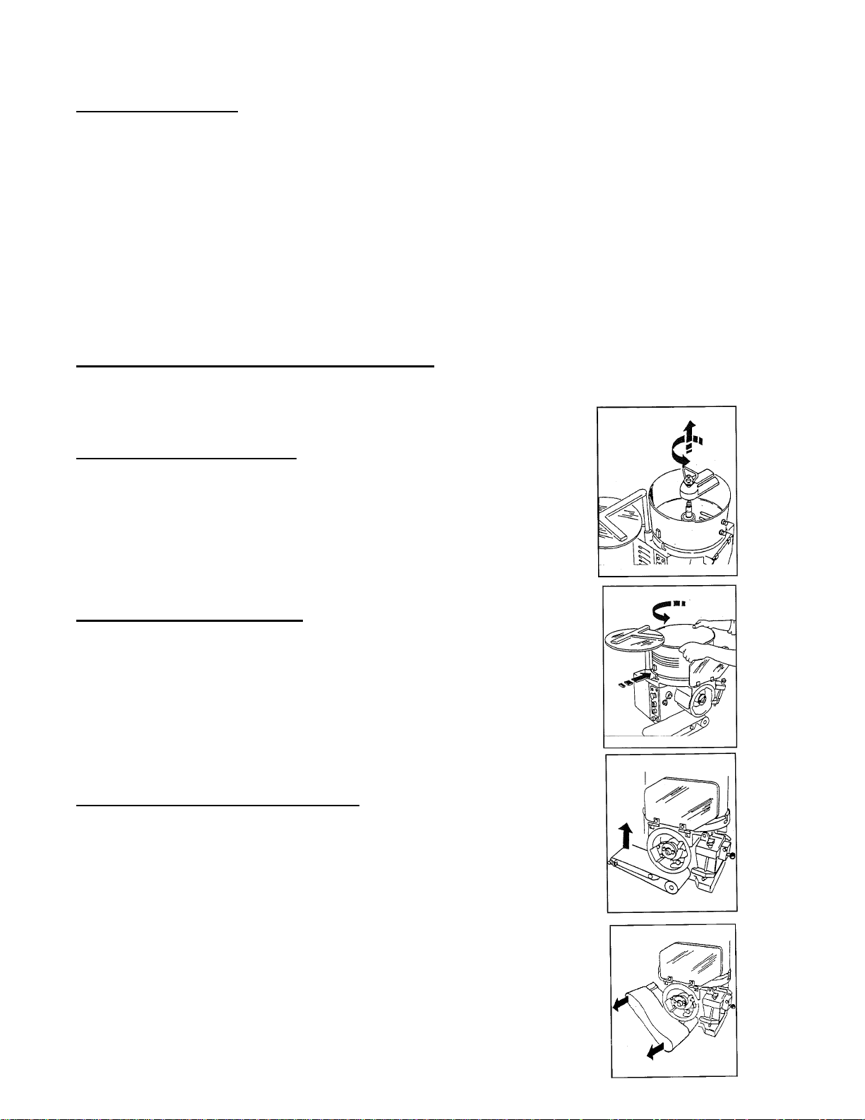
Disassembly of the Paddle
• Hold the handle, turn anti-clockwise and lift.
• To avoid accidents before disassembling, position
the paddle away from the hopper pins.
Disassembly of the Hopper
• Open the cover completely.
• Turn the hopper anti-clockwise,
lift it and take it away from the base.
Disassembly of the Conveyor Belt
• Lift the belt on the side of the return pulley.
• Take off and disassemble the conveyor belt.
11
Page 12

• Disassemble the complete conveyor from the guide pin.
Disassembly of the Regulation Drum
• Turn the stop ring nut anti-clockwise, pull the drum and disassemble it from the
control pin.
Disassembly of the Scraper
• Loosen the stop knob of the scraper shaft.
• Take off the complete scraper.
Cleaning of the Disassembled Components
• All the disassembled components must be washed with warm water, neutral detergent,
rinsed in water and dried.
Assembly of the Accessories
To effect the reassembly of the accessories, proceed in the inverse way to what previously
described in the disassembly. Pay special attention to the assembly of the following
accessories:
• Hopper: Insert the hopper with the two guide pins in the fusion taking care to
position the micro-magnet on the side of the cover shaft and turn it until it hooks the
pins.
• Paddle: position the inserting shaft of the paddle so that the pins in the hopper do not
overlap the paddle, then hold the paddle, put it on the shaft, making the shaft plug
coincide with the housing in the drum.
• Drum: assembly the drum in the guide pin, making the shaft plug coincide with the
housing in the drum.
MAINTENANCE
Ordinary Maintenance
The machine does not require a special maintenance for the regulations or replacements of
parts, but only requires a normal maintenance carried out by the operator which consists of
the following operations:
• Verify the operation of the micro-switches and of the electric buttons.
• Verify the state of use of the feeding wire.
Whenever there was the necessity of repairs or special maintenance, contact the assistance
service or a qualified technician.
12
Page 13

ABM
F2000N - F3000N - F4000N - B1200N
NSF / ETL VERSION
RECOMMENDED SPARE PARTS
77700 220V/50Hz.
77800 115V/60Hz.
76800
77100
40403
76600
597100
77000
19202
19201
Z9AMR
60600
60900
60000 COMPLETE ASSEMBLY
CODE DESCRIPTION Q.TY
F9319201 LONG CONVEYOR BELT 145x1850mm 1
F9319202 SHORT CONVEYOR BELT 145x840mm 1
F9340403 CERAMIC MAGNET 16x9, 5x8 1
F9360600 WIRE CLEANER 1
F9360900 S.S. WIRE 1
F9376800 MAGNET 1
F9377000 FOOTSWITCH 6210-OB 1
F9377100 PNEUM. SWITCH MOM.6871-01 1
F9377700 CARD 220/50 HZ START STOP FROM SN. 1710 1
F9377800 CARD 115/60 HZ START STOP FROM SN. 1710 1
F93597100 MALE COUPLING BODY 1
Z9AMR SAFETY CONTACT 1
CODE DESCRIPTION Q.TY
F9360000 CLEANER ASSEMBLY 1
F9313701 PADDLE NSF VERSION 1
NSF VERSION
13701-COMPLETE ASSEMBLY
PAG-0
Page 14

ABM
PNEUMATIC VERSION / ALL
NSF / ETL VERSION
RECOMMENDED SPARE PARTS
38003
38002
62600
60600
38006
38001
13701 Complete Assembly
60900
3800A Complete Assembly
CODE DESCRIPTION Q.TY
F9338001 CILINDER - ISO 6432 1
F9338002 AIR FILTER 1
F9338003 FIL BIT 1/8 20 RMSA 1
F9338006 SWITCH 1
F933800A COMPLETE PNEUMATIC CLEANER ASSEMBLY 1
F9362600 PNEUMATIC PISTON 1
F9360600 WI RE CLEANER 1
F9360900 S.S.WIRE 1
CODE DESCRIPTION Q.TY
F933800A CLEANER ASSEMBLY 1
F9313701 PADDLE 1
PAG-01
Page 15

ABM
F2000N - F3000N - F4000N - B1200N
NSF / ETL VERSION
12403
12401
10100
12702
F9314100
F9314100
11202
06300
12100
Z9CUS
12000
11900
19401
10600
10700
06800
CODE DESCRIPTION Q.TY
F9306300 BE ARING 51108 40x60x13 1
F9306800 SE AL A S 30x42x7 NB R 1
F9307000 BEA RING 6205 2RSH 25x 52x15 1
F9310100 F RA M E 1
F9310600 S HAFT HOUSING 1
F9310700 CA M 1
F9311202 CONIC GEA R 25x28,2 M 3 Z=25 1
F9311900 SHA F T d30x248 1
F9312000 P L UG 10x 46 h8 1
F9312100 KE Y 8x7x35 UNI 6605 69 A C 40 1
F9312401 B US HING 40x 16 E RTALON 1
F9312403 BUS HING 1
F9312702 BUS HING 26,7x32x39 1
F9314100 RUBB E R F OO T 4
F9319401 O RING 80x 3 1
PAG-1
Page 16

10302
A
ABM
F2000N - F3000N - F4000N - B1200N
NSF / ETL VERSION
06700
15100
19402
8401
8400
06300
12500
8501
8500
12600
11201
CODE DESCRIPTION Q.TY
F9306300 BE A RING 51108 40x60x 13 1
F9306700 SE A L A S 30x 42x7 NBR 1
F9308300 CHAIN P.8 ISO 9001 1
F9308400 BUS HING HK4020 1
F9308401 RING IR 35x40x 20. 5 1
F9308500 BUS HING 36x42x 20 HK 3520 1
F9308501 RING IR 30x35x 20 1
F9310301 HOPPER PLATE 1
F9311201 CONIC GEAR 30x 33, 2 M 3 Z=25 1
F93125V02 PA DDLE S HA F T d30x195 1
F9312600 KE Y 8x8x 45 1
F9315100
F9319402 O RING 69,3x5, 7 1
LU BUSHING 87x33,5 1
PAG-2
Page 17

10301
ABM
F2000 - F 3000 - F4000 - B1200 - HD3000
06800
15100
19402
8501
8500
8501
8500
06300
12600
12500
12600
11201
CODE DESCRIZIONE ARTICOLO DESCRIPTION Q.TY
F9306300 CUSCIN.51108 40x60x13 BEARING 51108 40x60x13 1
F9306800 ANELLO TEN. AS 30x42x7 NBR SEAL AS 30x42x7 NBR 2
F9308300 CATENA RCX P.8 semp.ISO 9001 L=568 (570) CHAIN P.8 ISO 9001 1
F9308500 BOCC.a RULL.36x42x20 HK3520 ordinare+ANELLO IR 30x35x20 BUSHING 36x42x20 HK3520 1
F9308501 ANELLO IR 30x35x20xBOCC.HK3520 RING IR 30x35x20xBOCC.HK3520 1
F9310301 CUPOLA F93 # HOPPER PLATE 1
F9311201 INGRAN.CONICO 25x28,2 M 3 Z=25 CONIC GEAR 25x28,2 M3 Z=25 1
F9312500 ALBERO RACLA d30x195 PADDLE SHAFT d30x195 1
F9312600 LINGUETTA 8x8x45 INOX 316 Tipo A non unificato con foro KEY 8x8x45 1
F9315100 BOCC.87x33,5 Alluminio ALU BUSHING 87x33,5 1
F9319402 ANELLO OR 69.3 x 5.7 NBR O RING 69,3x5,7 1
PAG-2
Page 18

ABM
F2000N - F3000N - F4000N - B1200N
NSF / ETL VERSION
11000
08000
08100
08101
10900
13101
19400
07600
19500
11500
11400
07600
11300
08300
13001
12301
CODE DESCRIPTION Q.TY
F9306400 RING 80x100x 10 1
F9307600 BE ARING 6003 2RS 17x35x10 2
F9308000 SE AL 17x28x 7 NB R 1
F9308100 BUS HING 1720x 16 NK 20 / 16 1
F9308101 RING 17x20x 16 1
F9308300 CHAIN P8 ISO 9001 1
F9308600 GEAR B O X RC 220 B5 1:30 1
F9308601 GEAR B O X RC 220 B5 1:46 - B 1200 1
F9310801 GEAR 80x 66 1
F9310900 CONVEY OR S HA F T SUP P ORT 60x67 1
F9311000 SHA F T 17 x 179 1
F9311100 CHAIN PINION 8x3 Z=21 1
F9311300 CHAIN PINION 8x3 Z=18 1
F9311400 RELEA S E GE AR M 1, 5 Z=32 1
F9311500 GEAR M 1,5 Z=38 1
F9311600 CAM P INION 8x3 Z=21 1
F9311700 SCRA P ER CAM 1
F9312301 RELEA S E S UP P O RT 1
F9312900 CAM P IN 12x 37 1
F9313001 RELEA S E S HA F T 17x115 1
F9313101 RELEA S E P IN 1
F9313202 GEAR P ULLE Y 53 x 31 - F 4000 1
F9313203 GEAR P ULLEY 53x31 F 4000 1
F9313204 GEAR P ULLEY 110x31 1
F9319400 O RING 9,25x1, 78 1
F9319500 BE ARING 6201 2RS 12x32x10 1
F9319905 BUS HING 12x 21x16 1
F9319906 RING 12x15x 16 1
06400
12900
11100
19906
19905
11600
10801
11700
08600
08601
13203
13204
13202
PAG-3
Page 19

12201
12800
13400
14300
14200
F9319600
ABM
F2000N - F3000N - F4000N - B1200N
NSF / ETL VERSION
60000
Complete Assembly
11800
G302
60600
60900
15400
14600
14500
14700
14800
CODE DESCRIPTION Q.TY
F9309400 S.S. LONG BELT 1
F9311800 SLIDING SUPPORT 1
F9312201 SCRAPER CONTROL LEVER 1
F9312800 PULLEY PIN 6x30 1
F9313400 CLEANER SPRING 1
F9314200 ARM ASSY 20x187 1
F9314300 RING 1
F9314400 CONVEYOR ROLL 64x140 1
F9314401 SS BELT DRIVER 64 x 140 1
F9314500 ROLL 28x140 1
F9314600 ROLL PIN 12x193 1
F9314700 LOCKING SCREW M8x38 1
F9314800 ROLL BUSHING 1
F9314901 SHORT CONVEYOR ARM 1
F9314902 LONG CONVEYOR ARM 1
F9315400 CONVEYOR ARM PIN 6x30 1
F9319201 LONG CONVEYOR BELT 145x1850mm 1
F9319202 SHORT CONVEYOR BELT 145x840mm 1
F9319600 BEARING 626-2RSH 1
G302 PLAST
F93606
F9360900 S.S. WIRE 1
CODE DESCRIPTION Q.TY
F9360000 CLEANER ASSEMBLY 1
14901
14902
IC KNOB D5 6G 1
00 WIRE CLEANER 1
09400
19202-SHORT
14400
14401
19201-LONG
PAG-4
Page 20

20301
ABM
F2000N - F3000N - F4000N - B1200N
NSF / ETL VERSION
20700
20801
20400
20000 - 20002 - 20003 - 20004
Complete Assembly
20300
20200
20600
20900
21100
21000
20500
25700
CODE DESCRIPTION Q.TY
F9320200 ALLUMINIUM FRAME 1
F932030
F9320301 PUSHER - 1
F9320400 PLATE SUPPORT 1
F9320500 GUIDE PLATE 1
F9320600 PUSHER SHAFT 2
F9320700 PIN 8X56,5 1
F9320801 PLASTIC BEARING d.14,5 2
F9320900 PUSHER SPRING 1
F9321000 LOCKING MECHANISM 1
F9321100 LOCKING MECHANISM SPRING 1
F9321200 THICKNESS CAM 1
F9321300 LOCKING THICKNESS MECHANISM 1
G305 PLASTIC KNOB - D3 6G 1
F9325700 RING . d 8 UNI 7435 2
CODE COMPLETE ASSEMBLY Q.TY
F9320000 DRUM SINGLE SHAPE ON REQUEST 1
F9320002 DRUM DOUBLE SHAPE ON REQUEST 1
F9320003 DRUM FOUR SHAPE ON REQUEST 1
F9320004 DRUM COOKIE ALLU - SHAPE ON REQUEST 1
0 PLASTIC DRUM 1
21200
21300
G305
PAG-5
Page 21

ABM
F2000N - F3000N - F4000N - B1200N
NSF / ETL VERSION
31500
31700
31900
31800
3010B-135MM
30100
30300
3030B-135MM
30202 Complete assembly
3160B-135MM
31600
21500
32000
32100
30500
30600
30400
30800
31000
30900
31300
31300
31100
30201 Complete assembly
30701
31100
CODE DESCRIPTION Q.TY
F9330400 PAPER HOUSING 1
F9321500 PLASTIC KNOB - D3 6G 1
F9330100 ALU PAPER ATTACH HOLDER 1
F9330300 PAPER MAGAZINE 1
F9330500 SCREW 6x160 1
F9330600 CAM 1
F9330700 GUIDING PIN 6x117 1
F9330701 KNOB 1
F9330800 PIN 1
F9330900 PAPER PUSHER 1
F9331000 PAPER PUSHER SPRING 1
F9331100 LOCKING PAPER PIN 2
F9331200 PIN 12x7,5 2
F9331300 SPRING 05 DE 11 2
F9331400 BUSHING 8x7,5 1
F9331500 SPRING d 10 L 55 1
F9331600 PIN 1
F9331700 RELEASE LEVER 1
F9331800 STOPPING SEAL 1
F9331900 PAPER ATTACHMENT SUPPORT PIN 1
F9332000 GUIDING PIN 8x55 1
F9332100 GUIDING PIN 6x48 1
F9332200 BUSHING 12x14x15 2
CODE COMPLETE ASSEMBLY Q.TY
F9330000 PAPER ATTACHMENT COMPLETE 1
F9330201 PAPER PUSHER ASSEMBLY 1
F9330202 PAPER SUPPORT ASSEMBLY 1
30000 Complete assembly
3000B-135MM Complete assembly
CODE DESCRIPTION Q.TY
F933160B SPRING PIN - 135 mm PAPER ATT. 1
F933010B ALU PAPER ATTACH HOLDER 135mm 1
F933030B PAPER MAGAZINE - 135 mm 1
CODE COMPLETE ASSEMBLY Q.TY
F933000B PAPE R ATTACH. COMPLETE 135 mm 1
PAG-6
Page 22

ABM
F2000N - F3000N - F4000N - B1200N
NSF / ETL VERSION
13701-COMPLETE ASSEMBLY
NSF VERSION
40302 EXTENDED HOPER
40300 STANDARD
76600
12402
50102 F4000
50100 STANDARD
12701
40202
40201
40100 STANDARD
40102 EXTENDED HOPER
50700
50400
50300
PAG-7
05600
06200
AF021
AF025
05701 COMPLETE ASSEMBLY
50200
CODE DESCRIPTION Q,TY
AF021 KNOB Ø40 M10 1
F9312402 BUSHING 1
F9305600 GUIDE 2
F9306200 METAL PLATE 2
AF025 PTFE WHEEL 2
F9312701 BUSHING 1
F9340100 HOPPER d360x260h 1
F9340102 HOPPER d360x430h 1
F9340201 HOPPER SHORT PIN 12x110 1
F9340202 HOPPER LONG PIN 12x130 1
F9340300 HOPPER COVER ARM 1
F9340302 EXT.HOPPER COVER ARM 1
F9376600 MAGNET SUPPORT 1
F9350100 SS REAR PROTECTION 1
F9350102 REAR PROTECTION F4000 1
F9350200 LEF T SIDE PROTECTION 1
F9350300 SS DRUM PROTECTION 205x300 1
F9350400 LOCKING KEY PIN 8x177 M4 1
F9350700 LOCKING LEFT AND RIGHT KEY 1
CODE DESCRIPTION Q,TY
F9305701 TILTING DEVICE - COMPLETE ASSEMBL 1
F9313701 PADDLE - COMPLETE ASSEMBL 1
Page 23

ABM
F2000N - F3000N - F4000N - B1200N
NSF / ETL VERSION
77700 220V-50Hz
77800 115V-60Hz
77500
K20004
77900
K20003
76200
77100
75300
76100
597800
76000
Z9AMR
50800
77000
40403
76400
76300
Z9AMR
76800
50801 COMPLETE ASSEMBLY
597100
CODE DESCRIPTION Q.TY
F9340403 CERAMIC MAGNET 16x9, 5x8 1
F9350800 PNEUM. FOOTSWITCH SUP. PROTEC. 1
F9375300 POTENTIOMETER F4000 R10K1 M22 MOELLER 1
F9376000 DOUBLE SWITCH 1
F9376100 HAND/FOOT SWITCH 1
F9376200 STOP BUTTON 1
F93763 SWITCH 1 NC SCREW 1
F93764 SWITCH 1 NO SCREW 1
F9376800 MAGNET 1
F9377000 FOOTSWITCH 6210-OB 1
F9377100 PNEUM. SWITCH MOM.6871-01 1
F93597100 MALE COUPLING BODY 1
F93597800 FEMALE COUPLING BODY 1
F9377500 INVERTER SYN10 S 220 05 AF IP65 S 50/60H Kw. 0,75 220V 1
F9377900 INVERTER SYN10 S 220 05 AF IP65 S 50/60H Kw. 0,75 115V 1
K20003 RED LAMP 1
K20004 GREEN LAMP 1
F9377700 CARD 220/50 HZ START STOP FROM SN. 1710 1
F9377800 CARD 115/60 HZ START STOP FROM SN. 1710 1
Z9AMR SAFETY CONTACT 1
CODE DESCRIPTION Q.TY
F9350801 FOOT SWITCH - COMPLETE ASSEMBL
1
PAG-8
Page 24

ABM
F2000N - F3000N - F4000N - B1200N
NSF / ETL VERSION
13300
13500
F2000/B1200
13201
08800
F3000/HD3000
13201
08900
F4000
13201
08700
13204
13203
13202
13201
75500
76101
76102
CODE DESCRIPTION Q.TY
F9308700 BELT - F 4000 PJ 457 J8 1
F9308800 BELT - F 2000 B 1200 PJ 559 J8 220 mm 1
F9308900 BELT - F3000 HD 3000 - PJ508 1
F9313201 MOTOR PULLEY 38 x 31- ALL 1
F9313202 GEAR PULLEY 53 x 31 - F 4000 1
F9313203 GEAR PULLEY - F 3000 HD 3000 83 x 31 1
F9313204 GEAR PULLEY - F 2000 110 x 31 1
F9313300 MOTOR SUPPORT 1
F9313500 MOTOR SPRING TENS 1
F9375500 MOTOR - LMR 71 230 V. 50 Hz F 2 - 3 - HD 3000 - B 1200 1
F9375501 MOTOR - LMR 71 115 V. 60 Hz F 2 - 3 - HD 3000 - B 1200 1
F9376101 MOTOR CAPACITOR BLACK 31,5 - 40 mf VLCA 280 40 : 60 1
F9376102 MOTOR F 2-3- B 1200 CAPACITOR WHITE 1
F9377600 MOTOR THREE PHASE F 4000 only 0,55 Kw 230/400 V 50Hz B14 1
75501
77600
PAG-9
Page 25

ABM
F2000N - F3000N - F4000N - B1200N
NSF / ETL
PNEUMATIC VERSION
3800A COMPLETE ASSEMBLY
60900
60600
38001
38006
62600
38002
38003
CODE DE SCRIPTION Q.TY
F9338001 CILINDER - ISO 6432 1
F9338002 AIR FILTER 1
F9338003 FIL BIT 1/8 20 RMSA 1
F9338006 SWITCH - 1
F9362600 PNEUMATIC PISTON 1
F9360600 WIRE CLEANER 1
F9360900 S.S.WIRE 1
CODE DE SCRIPTION Q.TY
F933800A COMPLETE PNEUMATIC CLEANER ASSEMBLY 1
PAG-10
Page 26

ABM COMPANYsrl
Page 27

ABM COMPANYsrl
Page 28

ABM COMPANYsrl
Page 29

ABM COMPANYsrl
Page 30

ABM COMPANYsrl
Page 31

ABM
CONVEYOR BELT FOR HD 3000
EDITION 2014-06-16
0-140616
Page 32

VT209
VT032
VA0027
VA0046
ZZVOL
VA0028
VA0060
VA0029
PA39
VA0030
VT126
VT458
ABM
CONVEYOR BELT FOR HD 3000
1-140616
CODE DESCRIPTION
PA39 SEAL 25-42-7
VA0027 ROLL OF REFERENCE
VA0028 SHAFT OF REFERENCE FOR ROLLER
VA0029 SHAFT ALIGNMENT
VA0030 DISK
VA0046 FLAT WASHER Ø30
VA0060 BEARING 61905-2RS (25-42-9)
VT032 RETAINING RING INTERNAL M42 SS
VT126
FLAT WASHER M6 SS
VT209 HEX HEAD SCREW M6-1.0x20 SS
VT458 HEX SOCKET SET SCREW FLAT POINT M8-1.25x35 SS
ZZVOL KNOB Ø40 M8 FEMALE
Page 33

ABM
CONVEYOR BELT FOR HD 3000
2-140616
VT126
VA0034
F9375504
VT063
VA0046
VA0059
VA0032
VA0033
VT491
VA0057
VT128
VT106
VA0055
VT206
VT231
F9375503
CODE DESCRIPTION
F9375503 MOTOR Kw 0,18 - Gr.63 - B14 - 230V SINGLE PHASE - IP55 + CAPACITOR 8µF
F9375504 MOTOR Kw 0,18 - Gr.63 - B14 - 115V-60Hz - IP55 + CAPACITOR 25µF
VA0032 SHAFT ROLLER MOTOR
VA0033 ROLLER MOTOR
VA0034 REACTION ARM
VA0046 FLAT WASHER Ø30
VA0055 PLASTIC SUPPORT UCFL 204 OPEN COD.69026
VA0057 PLASTIC SUPPORT UCFL 204 CLOSED COD.69016
VA0059 GEAR MT MRV40 RAPP 1:30 PAM 63 B14 VER. FOOD WHIT WHITE EPOXY COATING
VT063 PARRALLEL PIN M6m6x40 SS
VT106 ACORN HEX CAP M10-1.5 SS
VT126 FLAT WASHER M6 SS
VT128 FLAT WASHER M10 SS
VT206 HEX HEAD SCREW M6-1.0x12 SS
VT231 HEX HEAD SCREW M8-1.25x20 SS
VT491 KEY 6x6x20 INOX
Page 34

VA0042
VT229
VT127VT231
VT238
VA0046
PA43
VT127
VT127
VA0045
VA0043
VT105
VT127
VA0044
VT105
ABM
CONVEYOR BELT FOR HD 3000
3-140616
CODE DESCRI PTION
PA43 WHEELS PIVOTING Ø80 SS
VA0042 SUPPORT BAR
VA0043 SHORT LEG
VA0044 LONG LEG
VA0045 CROSS LEG
VA0046 FLAT WASHER Ø30
VT105 ACORN HEX CAP M8-1.25 SS
VT127 FLAT WASHER M8 SS
VT229 HEX HEAD SCREW M8-1.25x14 SS
VT231 HEX HEAD SCREW M8-1.25x20 SS
VT238 HEX HEAD SCREW M8-1.25x60 SS
S
S
PIVOTING WHEEL d.80 SS
Page 35

VA0040
VA0049
VA0038
VA0035
VA0037SX
VA0041
VA0039
VT127
VA0058
ZZVOL
VT126
VA0047
VT206
VT206
VA0024
VT104
VA0031
VT126
VA0026
VT206
VA0025
VT113
VA0048
VT127
VA0037DX
VA0050
VA0036
VT229
ABM
CONVEYOR BELT FOR HD 3000
4-140616
CODE DESCRI PTION
VA0024 MAIN BODY
VA0025 TILTING BODY
VA0026 PLATE FOR TILTING BODY
VA0031 HINGE SPACER
VA0035 PLATES RIGHT WITH REACTION
VA0036 PLATES LEFT
VA0037DX PLATE WITH ROD RIGHT
VA0037SX PLATE WITH ROD LEFT
VA0038 ROD
VA0039 BLIND NUT
VA0040 THROUGH NUT
VA0041 PIVOT BUSH
VA0047 BOX SCRAP COLLECTION
VA0048 ROD MOUNTING BOX
VA0049 HINGE PIN FOR CARTER
VA0050 CARTER OF MOTOR
VA0058 BELT 1N4B07PA_HBHACCP 145 X 2440
VT104 ACORN HEX CAP M6-1.0 SS
VT113 NYLOK NUT M8-1.25 SS
VT126 FLAT WASHER M6 SS
VT127 FLAT WASHER M8 SS
VT206 HEX HEAD SCREW M6-1.0x12 SS
VT229 HEX HEAD SCREW M8-1.25x14 SS
ZZVOL KNOB Ø40 M8 FEMALE
Page 36

THE BIRO MANUFACTURING COMPANY
1114 W. Main Street
Marblehead, Ohio 43440 U.S.A.
Ph. 419-798-4451 Fax 419-798-9106
service@birosaw.com; www.birosaw.com
 Loading...