

Page 1

ABM FOOD FORMER
MODELS
F2000 – F3000 - F4000 - B1200 – HD3000
OPERATION & SERVICE MANUAL &
PARTS LIST
* IMPORTANT SAFETY NOTICE *
This Manual contains important
safety instructions which must
be strictly followed when using this equipment.
Item No. #356-2-10-1
Page 2

TABLE OF CONTENTS
INTRODUCTION Page
Warranty…………………………………………………………. 3
Reliability………………………………………………………… 3
GENERAL TECHNICAL FEATURES
Description……………………………………………………….. 4
Main features…………………………………………………….. 4
Safety devices……………………………………………………. 5
Components description…………………………………………. 5
Overall measurements…………………………………………… 6
INSTALLATION
Packing check……………………………………………………. 6
Placing the machine……………………………………………… 6
Electrical connections……………………………………………. 6
Control panel…………………………………………………….. 7
Operating test……………………………………………………. 7
UTILITY
Loading the automatic paper attachment………………………… 8
Product thickness regulation……………………………………… 9
Loading the product and use……………………………………… 10
CLEANING AND HYGIENE
Complete cleaning………………………………………………… 11
Disassembly of the removable accessories………………………... 11
Disassembly of the paddle………………………………………… 11
Disassembly of the hopper………………………………………… 11
Disassembly of the conveyor belt…………………………………. 11
Disassembly of the regulation drum………………………………. 12
Disassembly of the scraper………………………………………… 12
Cleaning of the disassembled components………………………… 12
Assembly of the accessories……………………………………….. 12
MAINTENANCE
Ordinary maintenance……………………………………………… 12
WIRING DIAGRAMS & SPARE PARTS
Wiring diagrams…………………………………………………… 13
Spare Parts…………………………………………………………. 16
2
Page 3

WARRANTY
The installation, the starting, and the operating of the machine must be performed by
skilled personnel only, who knows the machine. The personnel assigned to the assistance
and maintenance must always follow the instructions contained in the manual. The food
forming machine must be used by trained personnel only. If necessary provide for the
personnel’s training, to learn the usual operations in order to assure the correct use of the
machine.
ABM disclaims all responsibility in case of:
• Assembly of the components of the machine and the electric connection not
effected according to the established rules;
• Improper use of the machine;
• Tampering the controls or the security protection;
• Use of non-original spare parts;
The warranty does not cover the normal use of the parts.
RELIABILITY
In case of improper use of the machine, it is possible to have injuries and accidents.
The food forming machine must be used only by the personnel who must know the
machine and the content of the manual:
• Make sure that unskilled personnel – and especially children – do not operate the
machine;
• Do not modify or remove the safety devices (covers and protections), especially
those installed at the meat inlet;
• Never tamper with the electric system;
• Use the machine with concentration avoiding distractions;
• Before cleaning and maintenance, always disconnect the machine from the supply
system;
• Periodically check the main supply wire, in case of breaks or bad functioning,
provide for the replacement by skilled personnel.
• Never go near the machine with loose hair, clothes, bracelets, chains, rings, ties, etc.
to avoid the chance that they become tangled in the moving parts of the machine;
• Stop the machine whenever it makes strange noises during the functioning;
• Always keep the working area clean and dry;
• Do not deal with the repairs if you are not able to eliminate the possible breakdowns,
but contact the technical assistance;
• The machine is made of accessories and parts especially designed in order to reduce
the maintenance and minimum.
3
Page 4

GENERAL TECHNICAL FEATURES
Description
• The ABM Food Forming machine is characterized by:
• Compactness and small overall measurements and with special features, able to
satisfy the producing requirements of both the great and the small distribution;
• Reliability and safety in the operation and the cleaning processes;
• Hygiene of the parts in contact with the product through the use of innovative
materials conformed to the current regulations;
• Precision and compactness of the finished product;
• Strength, easy use, controls and working stationing especially designed to optimize
ergonomics.
Main Features
• The castings are made of anticorrodal thermically treated with innovative material
for food, while all the other components have been made of stainless steel. These
parts are particularly fit to resist the corrosive agents of the products used and are in
conformity with the hygienic regulations for food;
• The moving parts are started by an electronic motor and the movement transmission
operates through a chain and mechanism;
• The hopper, the paddle, the conveyor belt, the drum and the accessories are easily
disassembled to effect a regular cleaning.
• The thickness of the product is adjustable;
• The quantity of the hamburgers produced per hour can be varied on request in the
models with current continue motors;
• The hopper and the moving of the product operate in a continuous way and this
allows a homogenous dough;
• The controls are easily identifiable and suitable to prevent accidental starting;
• The transmission parts are located inside the crankcase;
• The machine is equipped with a device which allows the cleaning of the roll during
functioning (scraper) and permits the separation of the products;
• Different drums are available, suitable o the forming of products with different
shapes;
• On request, the machine can be supplied with electrical motors of different tensions.
4
Page 5
Safety Devices
The Food Forming Machine is equipped with the following protection and safety devices:
• Safety micromagnet on the hopper;
• Plastic cover servo-assisted by a micromagnet;
• Protection and front cover of the removable parts;
• Handle of the paddle optimized to avoid crushing and use of keys or particular tools;
• Starting of the machine through reverser for servo-assisted manual or automatic
control;
• Emergency button
• Materials in conformity with the food hygienic regulations and fit to guarantee the
good resistance to oxidation.
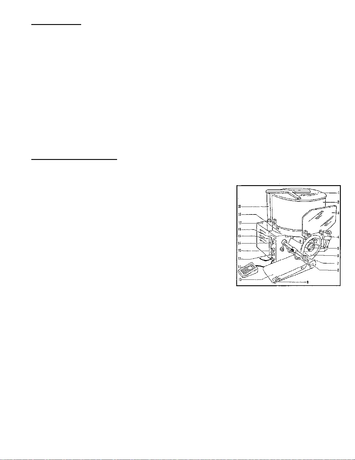
Components Description
CONTENTS
1. Cover
2. Hopper
3. Protection
4. Papering attachment
5. Drum stop ring nut
6. Drum
7. Scraper
8. Leading roll
9. Led roll
10. Conveyor belt
11. Footswitch
12. Speed variator for the mod. with current continuous
13. Manual/automatic switch
14. Stop button
15. Feeding signal light
16. Stop signal light
17. Transmission protection crankcase
18. Base
19. Cover shaft
5
Page 6
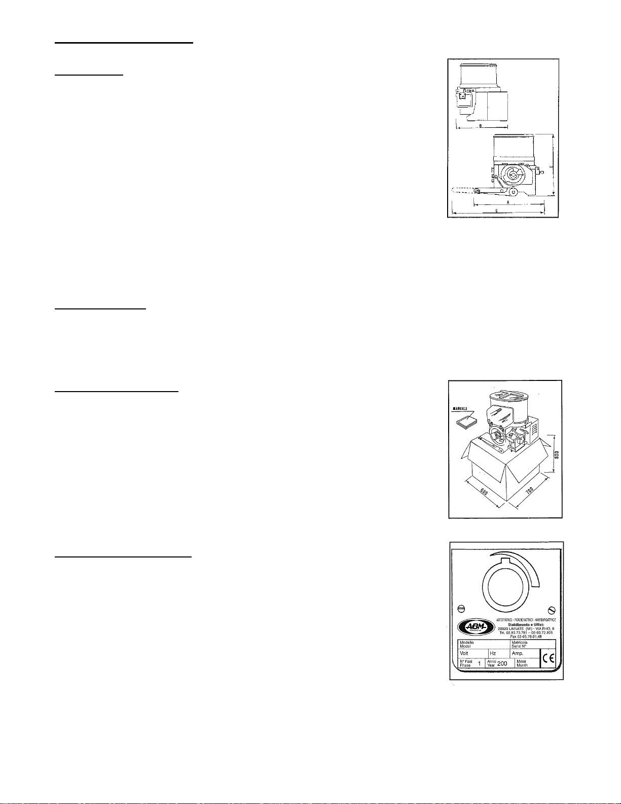
Overall Measurements
F2000/4000
Length (A) 620
Width (B) 500
Height (C) 610
Gross Created Weight – 72 kg.
Net Uncrated Weight – 67 kg.
Hopper capacity – 20 kg.
Optional Conveyor Belt – 1850 x 145
Hopper Power – see identification tag
Motor Power – see identification tag
INSTALLATION
Packing Check
• At the receipt of the machine, check the package to verify that the machine has not
been damaged.
The components of the package can be assimilated to the urban solid rubbish.
Placing the Machine
• It is advisable to place the Food Forming Machine
on a stable working table positioned on a height of
about 800mm from the ground.
• The installation area must allow the use of the machine
in an optimal and ergonomic way. It is advisable to
place it in a dry, breezy place, far from warmth sources;
it can be used without any special arrangement of a
normal working place.
Electrical Connections
• The machine is equipped with a feeding wire. Before
connecting it to the socket, verify the functioning tension
showed on the identification tag.
• In case the details do not correspond, contact the
distributor for the assistance service.
• The socket for the connection must correspond to
the current rules.
6
Page 7
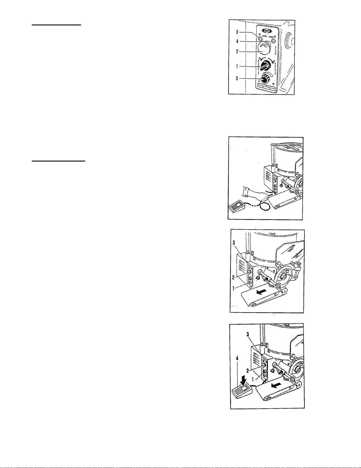
Control Panel
• Starting switch (automatic/manual) (1)
• Red stop button (2)
• Machine operating signal lamp (3)
• Machine stop signal lamp (4)
• Handle for speed regulation (5)
(only for model at variable speed)
Note – in the Model F4000 the regulation of the speed and the quantity of hamburgers
is made by rotating the regulating handle with a quantity of products variable from… to a
maximum of 4000 pieces per hour.
Operating Test
• Before controlling the operation, if you
have not already done, you must assemble
the hopper, assemble the conveyor belt,
close the cover and the front protection.
• Connect the footswitch, inserting the control
pipe into the bush on the control panel side.
• Connect the plug to the socket.
• Position the switch handle (1) on automatic.
• Verify the rotation of the drum and the
conveyor belt (see the arrow).
• Verify the lighting of the light.
• Push the stop button (2), the machine must
stop and the light (3) must light up.
• Position the switch handle (1) on manual.
• Press the footswitch.
• Verify the rotation of the drum and the
conveyor belt (see the arrow).
• Verify the lighting of the light.
• Push the stop button (2). The machine must stop
and the light (3) must light up.
7
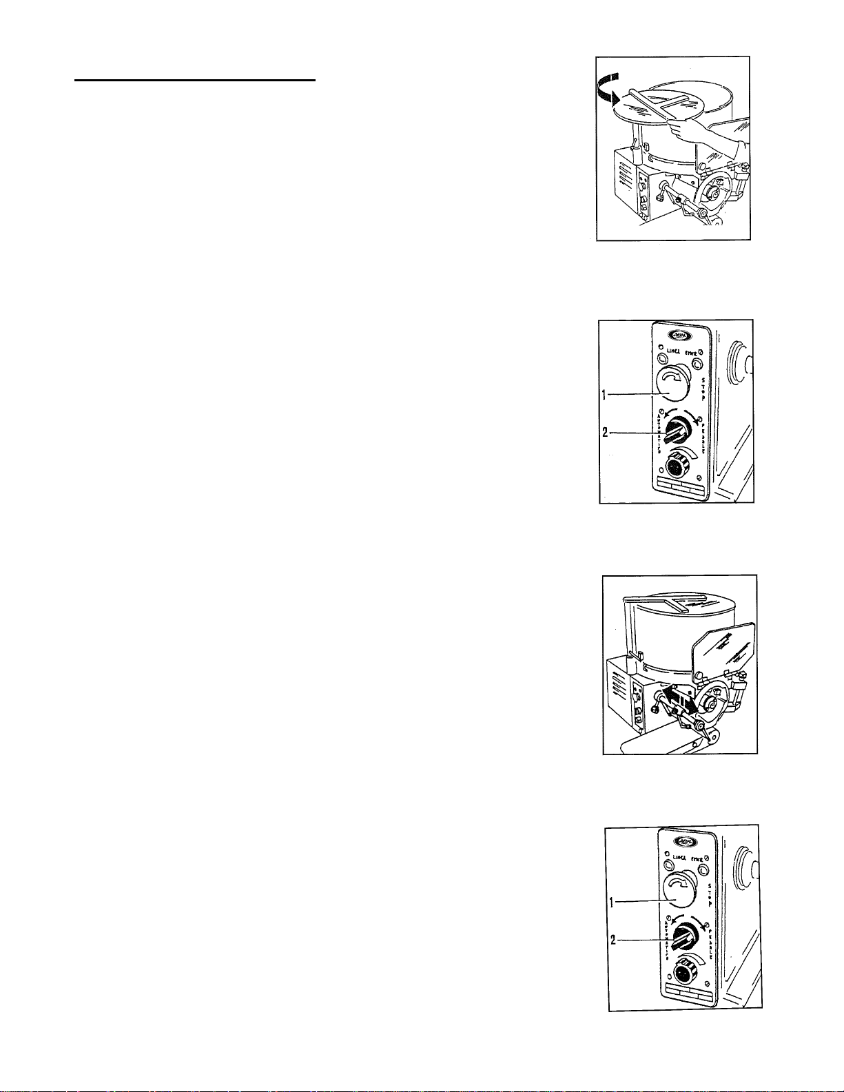
Page 8
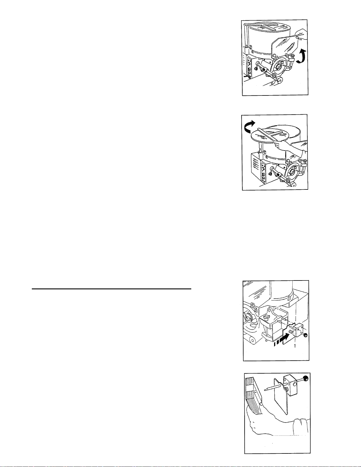
• During the operation, when lifting the front
drum protection, the machine must stop.
• To continue, close drum protection,
turn the operating switch again.
• During the operation, when rotating the
hopper cover, the machine must stop.
• To continue, close hopper cover,
turn the operating switch again.
UTILITY
To obtain good results you must use fitted meats and doughs. Arrange the machine with
all the accessories disassembled.
It is advisable not to use and let the machine function without any product in the
hopper.
Loading the Automatic Papering Attachment
• Take out the papering attachment by pushing
the button (I) and slipping it off from the guide pins.
• Replace the pushing spring.
• Insert the paper block and take away the wrapper.
8
Page 9

• Reassemble the papering attachment in the guide pins,
until the stop click.
• Release the spring using the button placed under
the papering attachment (2).
• Position the papering attachment, freeing the
locking lever (2).
• Regulate the center of the paper, turning the
centering knob (4).
Before cleaning the machine, always make sure that the machine
Is stopped and disconnected from main supply.
Never use high pressure sprays during cleaning.
Never use solvents, thin ners , alcohol, etc. during cleaning.
Only use lukewarm water and some neutral detergent.
Product Thickness Regulation
The machine is regulated in the factory with a medium thickness; to obtain another
thickness, follow the instructions indicated below:
• Take out the regulation drum by operating on the
ring nut clockwise and taking out the drum.
• Loosen the stop knob of the gauging device (I).
• Turn the gauging device, to regulate the thickness (2).
• Lock the stop knob (1).
• Reassemble the drum, inserting it in the guide shaft,
until the stop click.
9
Page 10
Loading the Product and Use
• Open the cover and load the product in the hopper
and close the cover again.
• Connect the plug to the socket.
• Start the machine: push the automatic switch (1).
• Regulate the production speed with the regulation handle (2)
(only for model with selector).
• During the operation, operate intermittently, in order
to clean the drum from residual product.
• The product will come down on the conveyor belt and
will be moved to its end.
• To stop the machine, operate on the stop button (I) or
open the protections.
• To continue, release the stop button and turn the start
switch again (2).
10
Page 11

CLEANING AND HYGIENE
Complete Cleaning
• It is advisable to clean the machine daily or if necessary more frequently, in case it
was very dirty or after long periods of inactivity.
• The cleaning must be carefully made for the parts in contact with the product.
• Clean the structure of the machine with soft cloths, sponges, and rinse with water
frequently. Finally dry with soft and dry cloths.
Attention: the machine is not protected against steam cleaners, high pressure power
washer, or similar systems. In this case there is risk of short circuit or serious damages to
the machine.
Disassembly of the Removable Accessories
• All the cleaning operations of the machine must always be done with the machine not
equipped with hopper, taking out the plug from the socket.
Disassembly of the Paddle
• Hold the handle, turn anti-clockwise and lift.
• To avoid accidents before disassembling, position
the paddle away from the hopper pins.
Disassembly of the Hopper
• Open the cover completely.
• Turn the hopper anti-clockwise,
lift it and take it away from the base.
Disassembly of the Conveyor Belt
• Lift the belt on the side of the return pulley.
• Take off and disassemble the conveyor belt.
11
Page 12

• Disassemble the complete conveyor from the guide pin.
Disassembly of the Regulation Drum
• Turn the stop ring nut anti-clockwise, pull the drum and disassemble it from the
control pin.
Disassembly of the Scraper
• Loosen the stop knob of the scraper shaft.
• Take off the complete scraper.
Cleaning of the Disassembled Components
• All the disassembled components must be washed with warm water, neutral detergent,
rinsed in water and dried.
Assembly of the Accessories
To effect the reassembly of the accessories, proceed in the inverse way to what previously
described in the disassembly. Pay special attention to the assembly of the following
accessories:
• Hopper: Insert the hopper with the two guide pins in the fusion taking care to
position the micro-magnet on the side of the cover shaft and turn it until it hooks the
pins.
• Paddle: position the inserting shaft of the paddle so that the pins in the hopper do not
overlap the paddle, then hold the paddle, put it on the shaft, making the shaft plug
coincide with the housing in the drum.
• Drum: assembly the drum in the guide pin, making the shaft plug coincide with the
housing in the drum.
MAINTENANCE
Ordinary Maintenance
The machine does not require a special maintenance for the regulations or replacements of
parts, but only requires a normal maintenance carried out by the operator which consists of
the following operations:
• Verify the operation of the micro-switches and of the electric buttons.
• Verify the state of use of the feeding wire.
Whenever there was the necessity of repairs or special maintenance, contact the assistance
service or a qualified technician.
12
Page 13

Page 14

ABM
HD 3000 PNEUMATIC
RICAMBI CONSIGLIATI
RECOMMENDED SPARE PARTS
38001
38003
38002
62600
13700-COMPLETE ASSEMBLY
60600
38006
60900
3800A Complete Assembly
CODE DESCRIZIONE DESCRIPTION Q.TY
F9338001 CILINDRO 1130160170CP ISO 6432 CILINDER - ISO 6432 1
F9338002 MR BIT 1/8 04 - FILTRO AIR FILTER 1
F9338003 FIL BIT 1/8 20 RMSA FIL BIT 1/8 20 RMSA 1
F9338006 VALV MEV 25 RSS 00 SWITCH - 1
F933800A GR.PULITORE PNEUM COMPLETE PNEUMATIC CLEANER ASSEMBLY 1
F9362600 PISTONE CILINDRO PULIT.PNEUM PNEUMATIC PISTON 1
F9360600 PULITORE FILO WIRE CLEANER 1
F9360900 FILO PULITORE Ø1mm S.S.WIRE 1
CODE DESCRIZIONE DESCRIPTION Q.TY
F9313700 RACLA HAMBURGATRICE PADDLE 1
PAG-01
Page 15

ABM
F2000 - F 3000 - F4000 - B1200 - HD3000
12403
12401
10100
12702
11202
06300
12100
Z9CUS
12000
11900
19401
10600
10700
06800
CODE DESCRIZIONE ARTICOLO DESCRIPTION Q.TY
F9306300 CUSCIN.51108 40x60x13 BE ARING 51108 40x60x13 1
F9306800 ANELLO TEN. AS 30x42x7 NBR SEAL AS 30x42x 7 NBR 1
Z9CUS CUSCIN.6205 2RSH 25x52x15 BE ARING 6205 2RSH 25x52x15 1
F9310100 BAS E F93 # FRAME 1
F9310600 MOZZO A LBERO TAMBURO # SHAFT HOUSING 1
F9310700 CAMMA ES PULSIONE CAM ERA CAM 1
F9311202 INGRAN.CONICO 30x33,2 M= 3 Z= 25 CONIC GEA R 30x 33,2 M 3 Z=25 1
F9311900 ALBERO TAMBURO d30x248 SHAFT d30x248 1
F9312000 SPINA 10x46 h8 (albero tamburo P LUG 10x46 h8 1
F9312100 LINGUE TTA 8x 7x 35 UNI 6605 69 A C40 (con foro) KE Y 8x 7x35 UNI 6605 69 A C 40 1
F9312401 BOCC. ant. BA SE 40x16 E rtalon B USHING 40x16 ERTALON 1
F9312403 BOCC.sup.Cupola/post.Base B USHING 1
F9312702 BOCC. 26,7x32x39 BUSHING 26,7x 32x39 1
F9319401 ANELLO OR 80 x 3 NBR O RING 80x 3 1
PAG-1
Page 16

10301
ABM
F2000 - F 3000 - F4000 - B1200 - HD3000
06800
15100
19402
8501
8500
8501
8500
06300
12600
12500
12600
11201
CODE DESCRIZIONE ARTICOLO DESCRIPTION Q.TY
F9306300 CUSCIN.51108 40x60x13 BEARING 51108 40x60x13 1
F9306800 ANELLO TEN. AS 30x42x7 NBR SEAL AS 30x42x7 NBR 2
F9308300 CATENA RCX P.8 semp.ISO 9001 L=568 (570) CHAIN P.8 ISO 9001 1
F9308500 BOCC.a RULL.36x42x20 HK3520 ordinare+ANELLO IR 30x35x20 BUSHING 36x42x20 HK3520 1
F9308501 ANELLO IR 30x35x20xBOCC.HK3520 RING IR 30x35x20xBOCC.HK3520 1
F9310301 CUPOLA F93 # HOPPER PLATE 1
F9311201 INGRAN.CONICO 25x28,2 M 3 Z=25 CONIC GEAR 25x28,2 M3 Z=25 1
F9312500 ALBERO RACLA d30x195 PADDLE SHAFT d30x195 1
F9312600 LINGUETTA 8x8x45 INOX 316 Tipo A non unificato con foro KEY 8x8x45 1
F9315100 BOCC.87x33,5 Alluminio ALU BUSHING 87x33,5 1
F9319402 ANELLO OR 69.3 x 5.7 NBR O RING 69,3x5,7 1
PAG-2
Page 17

ABM
F2000 - F 3000 - F4000 - B1200 - HD3000
11000
08000
08100
08101
10900
13101
19400
07600
19500
11500
11400
07600
11300
08300
13001
12301
06400
12900
11100
19906
19905
11600
10801
11700
08600
08601
13203
13204
13202
CODE DESCRIZIONE DESCRIPTION Q.TY
F9306400 ANELLO TEN. AS 80x100x10 NBR RING 80x100x10 1
F9307600 CUSCIN.6003 2RS 17x35x10 BEARING 6003 2RS 17x35x10 2
F9308000 ANELLO TEN. AS 17x28x7 NBR RING 17x28x7 1
F9308100 BOCC.a RULL.17x20x16 NK20/16 ordinare+ANELLO IR 17x20x16 BUSHING 1720x16 NK20/16 1
F9308101 ANELLO IR 17x20x16 RING 17x20x16 1
F9308300 CATENA RCX P8 ISO 9001 L=568 (570) CHAIN P8 ISO 9001 1
F9308600 RIDUTTORE RC 220 B5 1:30 F2000/3000/4000 GEAR BOX RC 220 B5 1:30 1
F9308601 RIDUTTORE RC 220 B5 1:46 B1200 GEAR BOX RC 220 B5 1:46 - B1200 1
F9310801 GIUNTO 80x66 GEAR 80x66 1
F9310900 SUPPORTO ALB. NASTRO 60x67 CONVEYOR SHAFT SUPPORT 60x67 1
F9311000 ALBERO Rullo conduttore 17x179 SHAFT 17 x 179 1
F9311100 PIGNONE CATENA COND.P.8x3 Z=21 CHAIN PINION 8x3 Z=21 1
F9311300 PIGNONE CATENA TR. P 8x3 Z=18 CHAIN PINION 8x3 Z=18 1
F9311400 INGRAN.RINVIO M 1,5 Z=32 RELEASE GEAR M 1,5 Z=32 1
F9311500 INGRAN.CONDOTTO M 1,5 Z=38 GEAR M 1,5 Z=38 1
F9311600 PIGNONE CAMMA PULIT.P 8x3 Z=21 CAM PINION 8x3 Z=21 1
F9311700 CAMMA PULITORE SCRAPER CAM 1
F9312301 SUPPORTO RINVIO REL EASE SUPPORT 1
F9312900 PERNO CAMMA PULITORE 12x37 CAM PIN 12x37 1
F9313001 ALBERO RUOTISMI RINVIO 17x115 RELEASE SHAFT 17x115 1
F9313101 PERNO STATICO RINVIO RELEASE PIN 1
F9313202 PULEGGIA RIDUTTORE 53x31 f4000 GEAR PULLEY 53 x 31 - F 4000 1
F9313203 PULEGGIA RID. 53x31 VEL.VARIABILE GEAR PULLEY 53x31 F4000 1
F9313204 PULEGGIA RID. 110x31 VEL.FISSA GEAR PULLEY 110x31 1
F9319400 ANELLO OR 9,25 x 1,78 NBR O RING 9,25x1,78 1
F9319500 CUSCIN.6201 2RS 12x32x10 BEARING 6201 2RS 12x32x10 1
F9319905 BOCC.a RULL.12x21x16 HK1516 ordinare+ANELLO IR 12x15x16 BUSHING 12x21x16 1
F9319906 ANELLO IR 12x15x16xBOCC.HK1516 vedi note RING 12x15x16 1
PAG-3
Page 18

12201
12800
13400
14500
14300
14200
15400
14600
ABM
F2000 - F 3000 - F4000 - B1200 - HD3000
11800
21500
600
Complete Assembly
60600
60900
14400
14401
14700
14800
CODE DESCRIZIONE ARTICOLO DESCRIPTION Q.TY
F9309400 NASTRO INOX S.S. LONG BELT 1
F9311800 SUPP.OSCILLANTE RASCHIATORE SLIDING SUPPORT 1
F9312201 LEVA COMANDO RASCHIATORE SCRAPER CONTROL LEVER 1
F9312800 PERNO TASTATORE PUL. 6x30 PULLEY PIN 6x30 1
F9313400 MOLLA TRAZIONE PULITORE CLEANER SPRING 1
F9314200 STELO BRACCIO 20x187 ARM ASSY 20x187 1
F9314300 RALLA SPALLAMENTO BRACCIO RING 1
F9314400 RULLO CONDUTTORE 64 x 140 CONVEYOR ROLL 64x140 1
F9314401 RULLO CONDUTTORE DENTATO SS BELT DRIVER 64 x 140 1
F9314500 RULLO CONDOTTO NASTRO 28x140 ROLL 28x140 1
F9314600 PERNO STATICO RULLO 12x193 ROLL PIN 12x193 1
F9314700 TENDITORE M8x38 LOCKING SCREW M8x38 1
F9314800 ANELLO SPALLAMENTO RULLO diam.20 foro 12 sp.7 mm ROLL BUSHING 1
F9314901 BRACCIO TRASP. CORTO SHORT CONVEYOR ARM 1
F9314902 BRACCIO TRASP. LUNGO LONG CONVEYOR ARM 1
F9315400 PIOLO BRACCIO TRASP. 6x30 C ONVEYOR ARM PIN 6x30 1
F9319201 NASTRO Trasportatore Lungo 145x1850mm LONG CONVEYOR BELT 145x1850mm 1
F9319202 NASTRO Trasportatore Corto 145x840mm SHORT CONVEYOR BELT 145x840mm 1
F9321500 VOLANTINO D5 6G PLASTIC KNOB D5 6G 1
F9360600 PULITORE FILO WIRE CLEANER 1
F9360900 FILO PULITORE ? 1mm S.S. WIRE 1
CODE DESCRIZIONE ARTICOLO DESCRIPTION Q.TY
F93600 ASSIEME PULITORE CLEANER ASSEMBLY 1
14901
14902
09400
19202-SHORT
19201-LONG
PAG-4
Page 19

20301
A
A
A
ABM
F2000 - F 3000 - F4000 - B1200 - HD3000
20700
20801
20300
20200
20600
20900
20500
25700
20400
21100
21000
20000 - 20002 - 20003 - 20004
Complete Assembly
21200
21300
21500
CODE DESCRIZIONE DESCRIPTION Q.TY
F9320200 MOZZO TAMBURO ALLUMINIUM FRAME 1
F9320300 STAMPO (TUBO POMc 200x140) E206 I133 H156 PLASTIC DRUM 1
F9320301 PIATTELLO ESPULSIONE # PUSHER - 1
F9320400 SUPP.PIATT.SUPER.x ST. a 1 fig PLATE SUPPORT 1
F9320500 PIASTRINA GUIDA ASTE CARRELLO GUIDE PLATE 1
F9320600 ASTA CARRELLO 8x122 PUSHER SHAFT 2
F9320700 PERNO STATICO TASTAT.8x56,5 PIN 8X56,5 1
F9320801 RULLINO TASTAT.CAMMA d.14,5 PLASTIC BEARING d.14,5 2
F9320900 MOLLA RITORNO PIATTELLO PUSHER SPRING 1
F9321000 AGGANCIO AUTOM.TAMBURO LOCKING MECHANISM 1
F9321100 MOLLA AGGANCIO AUTOMATICO LOCKING MECHANISM SPRING 1
F9321200 CAMMA CALIBR.SPESSORE THICKNESS CAM 1
F9321300 STAFFA CAMMA CALIBRATORE LOCKING THICKNESS MECHANISM 1
F9321500 VOLANTINO D3/6G mozzo lungo PLASTIC KNOB - D3 6G 1
F9325700 ANELLO EST. d 8 UNI 7435 RING . d 8 UNI 7435 2
CODE GRUPPO COMPLETO COMPLETE ASSEMBLY Q.TY
F9320000 GR. STAMPO 1 FIGUR
F9320002 GR. STAMPO 2 FIGUR
F9320003 GR. STAMPO 4 FIGUR
F9320004 GR. STAMPO ALLUMINIO BISCOTTI DRUM COOKIE ALLU - SHAPE ON REQUEST 1
DRUM SINGLE SHAPE ON REQUEST 1
DRUM DOUBLE SHAPE ON REQUEST 1
DRUM FOUR SHAPE ON REQUEST 1
PAG-5
Page 20

ABM
F2000 - F 3000 - F4000 - B1200 - HD3000
31500
31900
31800
31700
31600
30100
21500
30300
30202 Complete assembly
32000
32100
30500
30600
30400
30800
31000
30900
31300
31300
31100
30201 Complete assembly
30701
31100
30000 Complete assembly
CODE DESCRIZIONE ARTICOLO DESCRIPTION Q.TY
F9330400 CORPO CESTEL.CARTA PAPER HOUSING 1
F9321500 VOLANTINO D3/6G mozzo lungo PLASTIC KNOB - D3 6G 1
F9330100 CORPO INTERFOGLIATORE # ALU PAPER ATTACH HOLDER 1
F9330300 CESTELLO CARTA Rg # * con perno saldato F9330301> PAPER MAGAZINE 1
F9330500 VITE REGOLAZ.FASAT.CARTA 6x160 SCREW 6x160 1
F9330600 TASTATORE CAMMA ATT.FOGLIO CA. CAM 1
F9330700 STELO GUIDA CARR.INFOGL. 6x117 GUIDING PIN 6x117 1
F9330701 IMPUGN.A SFERA 3105 MEC A d20 KNOB 1
F9330800 BISTURI PIN 1
F9330900 SPINTORE CARTA Rg saldato PAPER PUSHER 1
F9331000 MOLLA COMPRESSIONE CARTA PAPER PUSHER SPRING 1
F9331100 PERNO BLOCCA CARRELLO CARTA LOCKING PAPER PIN 2
F9331200 PIOLO FERMO CARRELLO 12x7,5 PIN 12x7,5 2
F9331300 MOLLA COMP.FER.DF0,5-DE11-L25 SPRING 05 DE 11 2
F9331400 BUSSOLA FERMO CARR.8x7,5 BUSHING 8x7,5 1
F9331500 MOLLA RICH.CARR.CARTA d.10 L55 serve anche per le GD + UNI SPRING d 10 L 55 1
F9331600 PIOLO PER MOLLA RICHIAMO CARTA PIN 1
F9331700 LEVA ESCLUSIONE INTERFOGLIATOR RELEASE LEVER 1
F9331800 ANELLO D'ARRESTO INF.PERNO SUP STOPPING SEAL 1
F9331900 PERNO SUPPORTO INTERFOGLIATORE PAPER ATTACHMENT SUPPORT PIN 1
F9332000 PERNO GUIDA INFOGLIATORE 8x55 GUIDING PIN 8x55 1
F9332100 PERNO GUIDA INTERFOGL. 6x48 GUIDING PIN 6x48 1
F9332200 BOCC.PCM 121415E (Interf) BUSHING 12x14x15 2
CODE GRUPPI COMPLETI COMPLETE ASSEMBLY Q.TY
F9330000 GRUPPO INFOGLIATORE COMPLETO PAPER ATTACHMENT COMPLETE 1
F9330201 GRUPPO PRESSACARTA COMPLETO PAPER PUSHER ASSEMBLY 1
F9330202 GRUPPO SUPPORTO CARTA COMPLETO PAPER SUPPORT ASSEMBLY 1
PAG-6
Page 21

ABM
F2000 - F 3000 - F4000 - B1200 - HD3000
40302 EXTRA
40300 STANDARD
40500
50102 F4000
50100 STANDARD
13700-COMPLETE ASSEMBLY
13601-COMPLETE ASSEMBLY
40202
40201
40100 STANDARD
40102 EXTRA
12402
12701
50200
CODE DESCRIZIONE DESCRIPTION Q,TY
F9312402 BOCC.superiore CUPOLA BUSHING 1
F9312701 BOCC.inferiore CUPOLA BUSHING 1
F9340100 CONTENITORE d 360x260h # HOPPER d360x260h 1
F9340102 CONTENITORE d 360x430h # HOPPER d360x430h 1
F9340201 PERNO CONT. CORTO 12x110 HOPPER SHORT PIN 12x110 1
F9340202 PERNO CONT.LUNGO 12x130 HOPPER LONG PIN 12x130 1
F9340300 BRACCIO COPERCH.CONTEN. STD HOPPER COVER ARM 1
F9340302 BRACCIO COPERCH.CONTEN. ALTO EXT.HOPPER COVER ARM 1
F9340500 PUNTALE PROTEZ.SENSORE CONTEN. MAGNET SUPPORT 1
F9350100 PROT.POSTERIORE INOX # kg 4 AISI 304 SS REAR PROTECTION 1
F9350102 PROT. POSTER. F 4000 REAR PROTECTION F4000 1
F9350200 PROTEZIONE Laterale Sx LEFT SIDE PROTECTION 1
F9350300 PROT.STAMPO 205x300 # AISI 304 SS DRUM PROTECTION 205x300 1
F9350400 PERNO CERNIERA 8x177 M4 LOCKING KEY PIN 8x177 M4 1
F9350700 CERNIERE INOX DX-SX Ex F9350401 LOCKING LEFT AND RIGHT KEY 1
CODE DESCRIZIONE DESCRIPTION Q,TY
F9313601 GR. RACLA HAMBURGATRICE INOX S.S. PADDLE LARGER 1
F9313700 GR. RACLA HAMBURGATRICE PADDLE - COMPLETE ASSEMBL 1
50700
50400
50300
PAG-7
Page 22

F2000 - F 3000 - F4000 - B1200 - HD3000
FROM SERIAL NUMBER:1710
77800 115V-60Hz.
77700 220V-50Hz.
ABM
Z9SCH 220V-50Hz
Z9TCA 115V-60Hz
77500
K20004
77900
K20003
76200
75300
77100
76100
77200
76000
Z9AMR
40403
76400
76300
Z9AMR
76800
50801
50800
77000
CODE DESCRIZIONE DESCRIP T I O N Q.TY
F9340403 MAG NE TE CE RA M .2S 16x 9, 5x 8 M A x CONTENITORE F9340100 CERA M IC MA G NE T 16x9, 5x 8 1
F9350800 PROT.SUP . P E DA LE P neum atic o P NE UM . FO OTS WITCH S UP . P ROTEC. 1
F9375300 POTENZIOMETRO F 4000 M O E LLE R M 22 - R10K 1 POTENTIOME TER F4000 R10K 1 M 22 M O E LLE R 1
F9376000 CONTATTO DOP P IO DOUBLE S WITCH 2
F9376100 SELE TT. MANO / PIEDE - TUTTE HA ND/F OO T SWITCH 1
F9376200 PULSA NTE S TOP STOP BUTTON 1
F9376300 CO NTATTO 1 NC VITE SWITCH 1 NC SCREW 1
F9376400 CO NTATTO 1 NO VITE S WITCH 1 NO SCREW 1
F9376800 MAG NE TE CE RA M .2S x P RO TEZIONE M A G NE T 1
F9377000 PEDA LE 6210-OB (F93/CF 17) F OO TSWITCH 6210-O B 1
F9377100 INT.PNE UM . DE V IAZ. MO M .6871-01 PNE UM . S WITCH MOM. 6871-01 1
F9377200 PASSAPARETE x PEDALE PM1206E FOOTSWITCH CONNECTION PM1206E 1
F9377500 INV E RTER S Y N10 S 220 05 A F IP65 S 50/60H K w 0,75 220V INVERTER S Y N10 S 220 05 A F IP65 S 50/ 60H K w. 0, 75 220V 1
F9377900 INVE RTER S Y N10 S 220 05 A F IP65 S 50/ 60H K w 0,75 115V INVERTER S Y N10 S 220 05 A F IP65 S 50/60H K w. 0,75 115V 1
K20003 LA M P A DINA ROS SA RED LA M P 1
K20004 LA M P A DINA V E RDE GRE E N LA M P 1
F9377700 S CHE DA M / A RRE S TO 220 50 HZ DA S N. 1710 CARD 220/50 HZ START STOP F ROM S N. 1710 1
F9377800 S CHE DA M / A RRE S TO 115 - 60 HZ DA SN. 1710 CARD 115/60 HZ START STOP F ROM S N. 1710 1
Z9AMR SE NS O RE S ICUREZZA HAM B SA F E TY CO NTACT 1
Z9SCH S CHE DA M / A RRE S TO 220 50 HZ CARD 220/ 50 HZ START STOP 1
Z9TCA S CHE DA M /A RRE S TO 115 - 60 HZ CARD 115/60 HZ START STOP 1
CODE DESCRIZIONE DESCRIP T I O N Q.TY
F9350801 GR. PEDALE Pn e u m atico HAM B FOOT S WIT CH - COM P LETE AS S EMBL
1
PAG-8
Page 23

ABM
F2000 - F 3000 - F4000 - B1200 - HD3000
13300
13500
F2000/B1200
13201
08800
F3000/HD3000
13201
08900
F4000
13201
08700
13204
13203
13202
13201
75500
76101
76102
CODE DESCRIZIONE DESCRIPTION Q.TY
F9308700 CINGHIA F4000 POLY V 508J8 sv 200 BELT - F 4000 PJ 457 J8 1
F9308800 CINGHIA F2000 B1200 PJ 559 J8 PJ 559 J8 220 mm BELT - F 2000 B 1200 PJ 559 J8 220 mm 1
F9308900 CINGHIA F3000 HD 3000 PJ 533 BELT - F3000 HD 3000 - PJ533 1
F9313201 PULEGGIA MOTORE HAMB 38 x 31 tutti i modelli MOTOR PULLEY 38 x 31- ALL 1
F9313202 PULEGGIA RIDUTTORE 53x31 f4000 GEAR PULLEY 53 x 31 - F 4000 1
F9313203 PULEGGIA RIDUTTORE 83x31 F3000 F 3000 HD GEAR PULLEY - F 3000 HD 3000 83 x 31 1
F9313204 PULEGGIA RIDUTTORE 110x31F2000 GEAR PULLEY - F 2000 110 x 31 1
F9313300 SUPPORTO MOTORE HAMBURGATRICE TUTTE MOTOR SUPPORT 1
F9313500 MOLLA TENDITORE MOTORE MOTOR SPRING TENS 1
F9375500 MOT.M71S2K-35161 LMR71 vel fix kw 0,55 230V 50Hz B14 rot.ant MOTOR - LMR 71 230 V. 50 Hz F 2 - 3 - HD 3000 - B 1200 1
F9375501 MOT.F2000 M71S2K 35150 USA kw 0,55 115V 60 Hz MOTOR - LMR 71 115 V. 60 Hz F 2 - 3 - HD 3000 - B 1200 1
F9376101 CONDENSAT MOT 31,5 40 mf nero VLCA 280 40 - 60 MOTOR CAPACITOR BLACK 31,5 - 40 mf VLCA 280 40 : 60 1
F9376102 CONDENSAT MOT bianco MOTOR F 2-3- B 1200 CAPACITOR WHITE 1
F9377600 MOT. TR PER F 4000 AMI 71Z BA2 0,55 Kw 230/400 V 50Hz B14 MOTOR THREE PHASE F 4000 only 0,55 Kw 230/400 V 50Hz B14 1
75501
77600
PAG-9
Page 24

38001
ABM
F2000 - F 3000 - F4000 - B1200 - HD3000
PNEUMATIC VERSION
3800A
60900
60600
62600
38006
38002
38003
CODE DESCRIZIONE DESCRIPTION Q.TY
F9338001 CILINDRO 1130160170CP ISO 6432 CILINDER - ISO 6432 1
F9338002 MR BIT 1/8 04 - FILTRO AIR FILTER 1
F9338003 FIL BIT 1/8 20 RMSA FIL BIT 1/8 20 RMSA 1
F9338006 VALV MEV 25 RSS 00 SWITCH - 1
F9362600 PISTONE CILINDRO PULIT.PNEUM PNEUMATIC PISTON 1
F9360600 PULITORE FILO WIRE CLEANER 1
F9360900 FILO PULITORE Ø1mm S.S.WIRE 1
CODE DESCRIZIONE DESCRIPTION Q.TY
F933800A GR.PULITORE PNEUM COMPLETE PNEUMATIC CLEANER ASSEMBLY 1
PAG-10
Page 25

ABM COMPANYsrl
Page 26

ABM COMPANYsrl
Page 27

ABM COMPANYsrl
Page 28

ABM MODEL F4000 INVERTER
Page 29

WIRING DIAGRAM
Models F2000 / F3000 / HD3000
Contents: TR = Transformer 0/115/230 – 0/24
K1 = Motor Contactor
PE = Emergency Button
MS1= Security Microswitch
MS2= Security Microswitch
Position A = Impulsive Function
Selector Functions: S1 Position Ø = Stopped Machine
Position B = Retentive Function
MT = Motor
LE = Emergency Signal Lamp
LT = Tension Signal Lamp
TS = Signal Transection
13
Page 30

WIRING DIAGRAM
Model F4000
Contents: TR = Transformer 0/115/230 – 0/24
K1 = Motor Contactor
PE = Emergency Button
MS1= Security Microswitch
MS2= Security Microswitch
Position A = Impulsive Function
Selector Functions: S1 Position Ø = Stopped Machine
Position B = Retentive Function
L1/MP = Feeding 220 Vac
T1/T2 = Start/Stop Board
Ø = Signal Lamps
1 = Emergency
3/4 = Security Switches
5 = Selector
6 = Automatic
7 = Foot Switch
MT = Motor
LE = Emergency Signal Lamp
LT = Tension Signal Lamp
TS = Signal Transection
14
Page 31

HD3000
CONVEYOR ASSEMBLY
15
Page 32

THE BIRO MANUFACTURING COMPANY
1114 W. Main Street
Marblehead, OH 43440 USA
Ph. 419-798-4451 Fax 419-798-9106
Email: service@birosaw.com
16
 Loading...