

Page 1
+
IMPORTANT NOTICE
This Manual contains important
safety instructions which must
be strictly followed when using
this equipment.
+
PTCT
PTCT
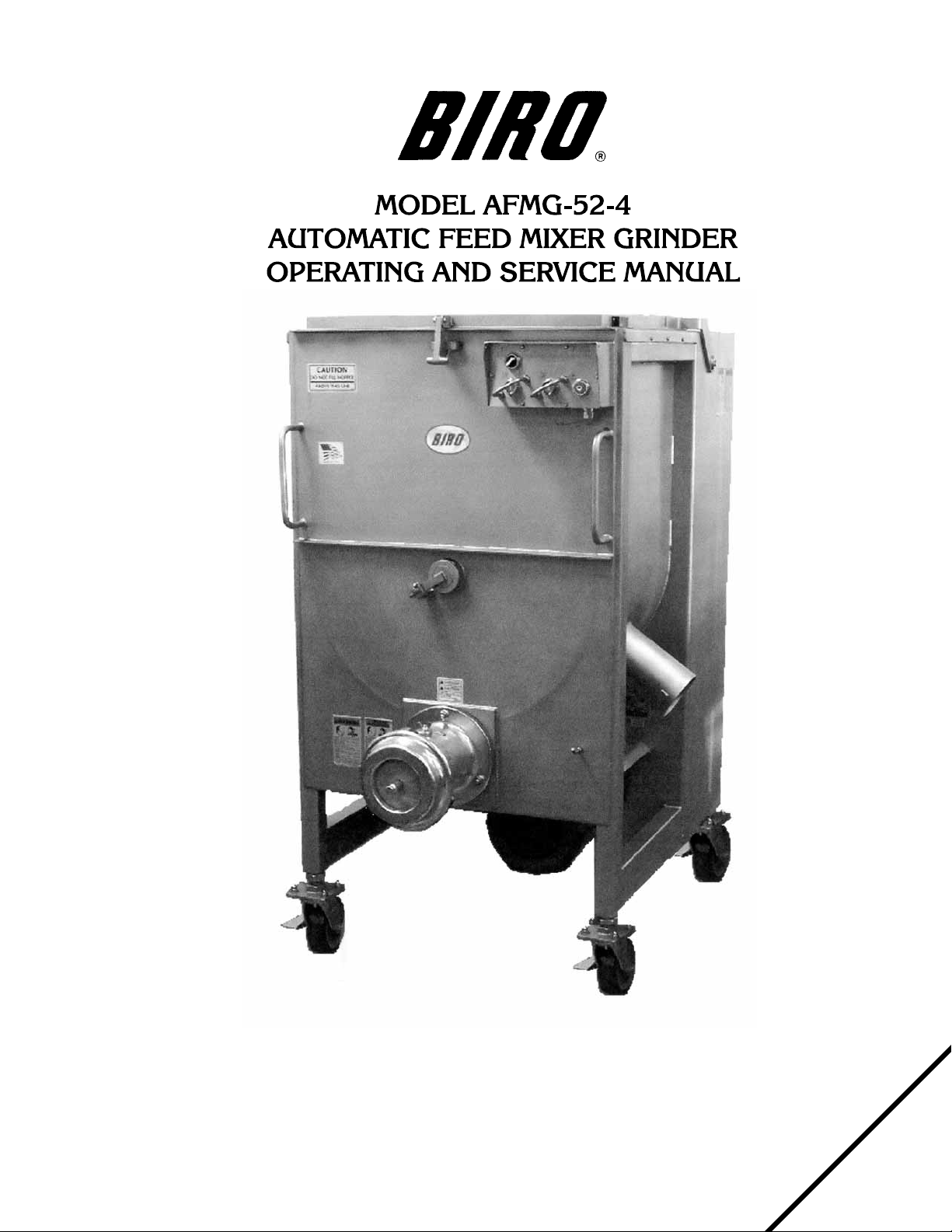
AFMG-52-4
AFMG-52-4
332-5-06-1
332-9-07-2
Page 2
Page 3

TABLE OF CONTENTS
Page
NOTICE TO OWNERS AND OPERATORS ......................................... 1
SAFETY TIPS ............................................................... 2
INSTALLATION ............................................................. 3
UNCRATING AND SETUP ................................................ 3
MOTOR WIRING AND ELECTRICAL REQUIREMENTS .......................... 4
STEP ASSEMBLY....................................................... 4
OPERATION ................................................................ 6
TO PROCESS PRODUCT ................................................ 6
CLEANING ................................................................. 7
MAINTENANCE ............................................................. 8
GRINDING BOWL INSTALLATION ......................................... 8
MIXING PADDLE INSTALLATION .......................................... 8
LUBRICATION ....................................................... 8-11
WINSMITH GEAR REDUCER LUBRICATION ................................9-10
SPUR GEARS LUBRICATION..............................................11
MIXER DRIVE GEAR ADJUSTMENT.........................................11
MAIN DRIVE CHAIN AND SPROCKET LUBRICATION ...........................11
MAIN DRIVE CHAIN TENSION.............................................12
CHAIN REPLACEMENT ..................................................12
PARTS DIAGRAMS ........................................................13-23
JOURNAL BOX ........................................................21
OPTIONAL STAINLESS STEEL BOWLS, AUGERS & END RINGS
(130mm UNGER & ENTERPRISE) ..........................................21
ELECTRICAL COMPONENT ASSEMBLY .....................................23
WIRING DIAGRAMS ..................................................24-25
ELECTRIC AND PNEUMATIC FOOTSWITCH .................................26
ITEMS REQUIRED FOR TANDEM OPERATION .....................................27
CONNECTION INSTRUCTIONS FOR TANDEM OPERATION ........................28-30
SAFETY LABEL LOCATIONS ...................................................31
OPERATOR'S SIGNATURE PAGE ................................................32
LIMITED WARRANTY .........................................................33
Page 4
NOTICE TO OWNERS AND OPERATORS
BIRO’s products are designed to process food products safely and efficiently. Unless the operator is properly trained and supervised, however, there is the possibility of a serious injury. It is the
responsibility of the owner to assure that this machine is used properly and safely, strictly following
the instructions contained in this Manual and any requirements of local law.
No one should use or service this machine without proper training and supervision. All operators should be thoroughly familiar with the procedures contained in this Manual. Even so, BIRO
cannot anticipate every circumstance or environment in which its products will be used. You, the
owner and operator, must remain alert to the hazards posed by the function of this equipment —
particularly the ROTATING GRINDING AUGER and the ROTATING MIXING PADDLE, which can
severely injure an inattentive operator amputating fingers and limbs. No one under eighteen (18)
years of age should operate this equipment. If you are uncertain about a particular task, ask your
supervisor.
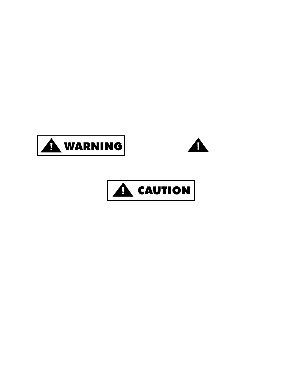
This Manual contains a number of safe practices in the SAFETY TIPS section. Additional warnings are placed throughout the Manual. Warnings related to your personal safety are indicated by:
OR
Warnings related to possible damage to the equipment are indicated by:
BIRO also has provided warning labels on the equipment. If any warning label or Manual becomes misplaced, damaged, or illegible, please contact your nearest Distributor or BIRO directly
for a replacement.
Remember, however, this Manual or the warning labels do not replace the need to be alert and
to use your common sense when using this equipment.
– NOTE –
“A copy of this manual is included with each MODEL AFMG 52-4 MIXER GRINDER.”
“ e descriptions and illustrations contained in this manual are not binding. e manufacturer reserves the right to introduce any modifi cation without updating the manual.”
1
Page 5
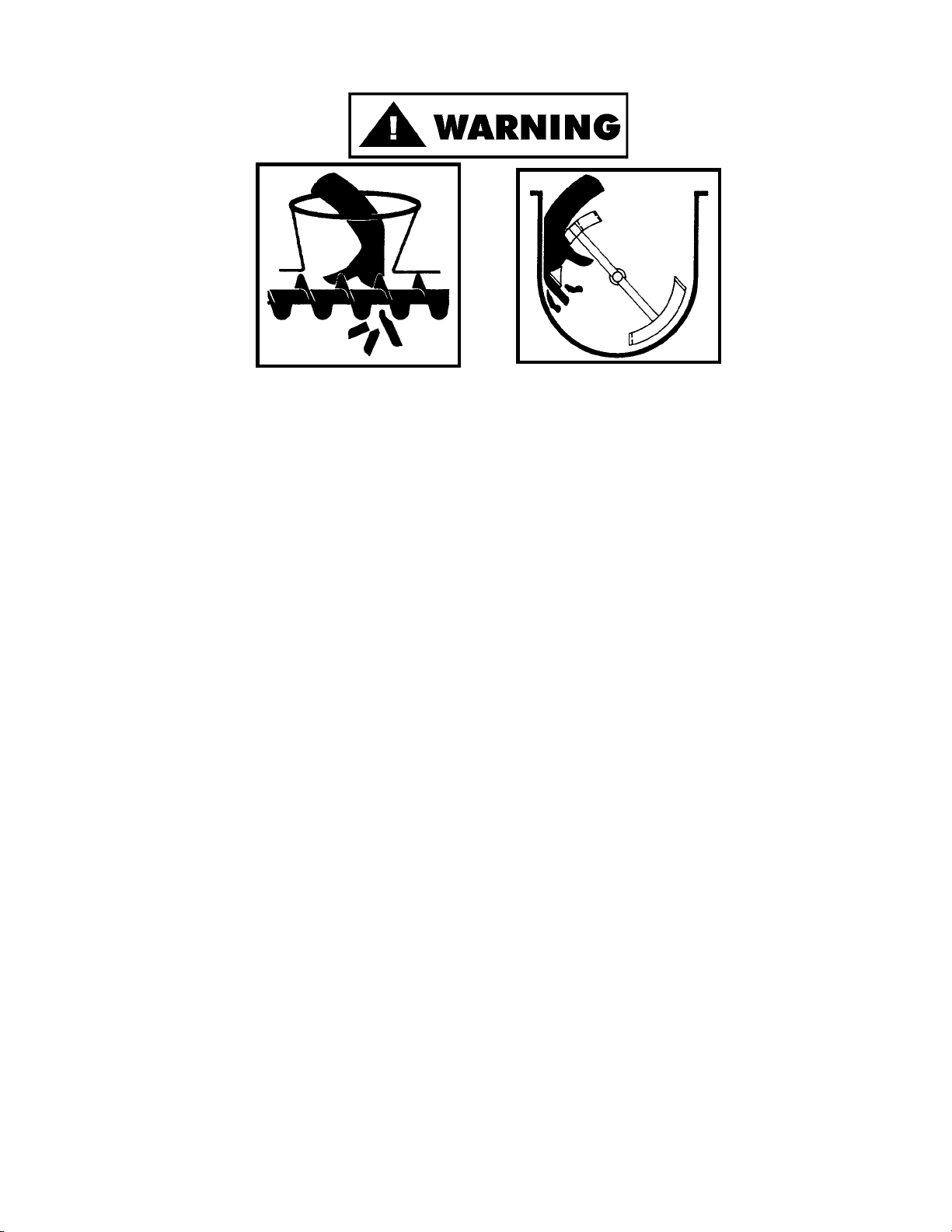
SAFETY TIPS
ROTATING GRINDING AUGER & ROTATING MIXING PADDLE
TO AVOID SERIOUS PERSONAL INJURY
· NEVER Touch This Machine without Training and Authorization by Your Supervisor.
· NEVER Place Hands into Machine Input or Output Openings.
· NEVER Open Machine During Operation.
· ONLY Use a Qualified Electrician to Install According to Local Building Codes: Machine MUST
Be Properly Grounded.
· ALWAYS Connect to Proper Voltage & Phase.
· ONLY Install on Level, Non-Skid Surface in a Clean, Well-Lighted Work Area Away from
Children and Visitors.
· ALWAYS Lock Machine Castors After Moving This Machine.
· NEVER Use This Machine For Non-Food Products.
· NEVER Operate Machine With Product Mixer Safety Cover Open or Removed or Magnetic
Interlock Switch By-Passed.
· ALWAYS Turn Off, Unplug Machine From Power Source and Perform Lockout/Tagout
Procedure to this Machine BEFORE Attempting to Unjam or Unclog, Cleaning or Servicing
· NEVER Leave Machine Unattended While Operating.
· NEVER Alter This Machine From its Original Form as Shipped From Factory. DO NOT
Operate Machine With Missing Parts.
· PROMPTLY REPLACE Any Worn or Illegible Warning Labels.
· ALWAYS Read Operation and Service Manual BEFORE Operating, Cleaning, or Servicing.
· USE ONLY BIRO Parts and Accessories Properly Installed.
2
Page 6

INSTALLATION
TO AVOID SERIOUS PERSONAL INJURY, PROPERLY INSTALL
EQUIPMENT IN ADEQUATE WORK AREA
· ALWAYS Use Qualified Technician and Electrician for Installation.
· ALWAYS Connect to Proper Voltage & Phase.
· ALWAYS Install Equipment in Work Area with Adequate Light and Space Away From Children
and Visitors.
· ONLY Operate on a Solid, Level, Non-Skid Surface.
· ALWAYS Lock Machine Castors After Moving Machine to Operating Location.
· NEVER Bypass, Alter, or Modify This Equipment in Any Way From Its Original Condition.
· NEVER Operate With Product Mixer Safety Cover Opened or Removed or Magnetic Interlock
Switch by-Passed.
· NEVER Operate Without all Warning Labels Attached and Owner/Operator Manual Available to
the Operator.
UNCRATING AND SET UP
1. Read this Manual thoroughly before installation and operation. Do not proceed with installation and operation if
you have any questions or do not understand anything in this Manual. Contact your local Distributor, or BIRO
first.
2. Remove all banding, shipping carton, and all equipment from inside the tub. Then take machine off shipping
pallet.
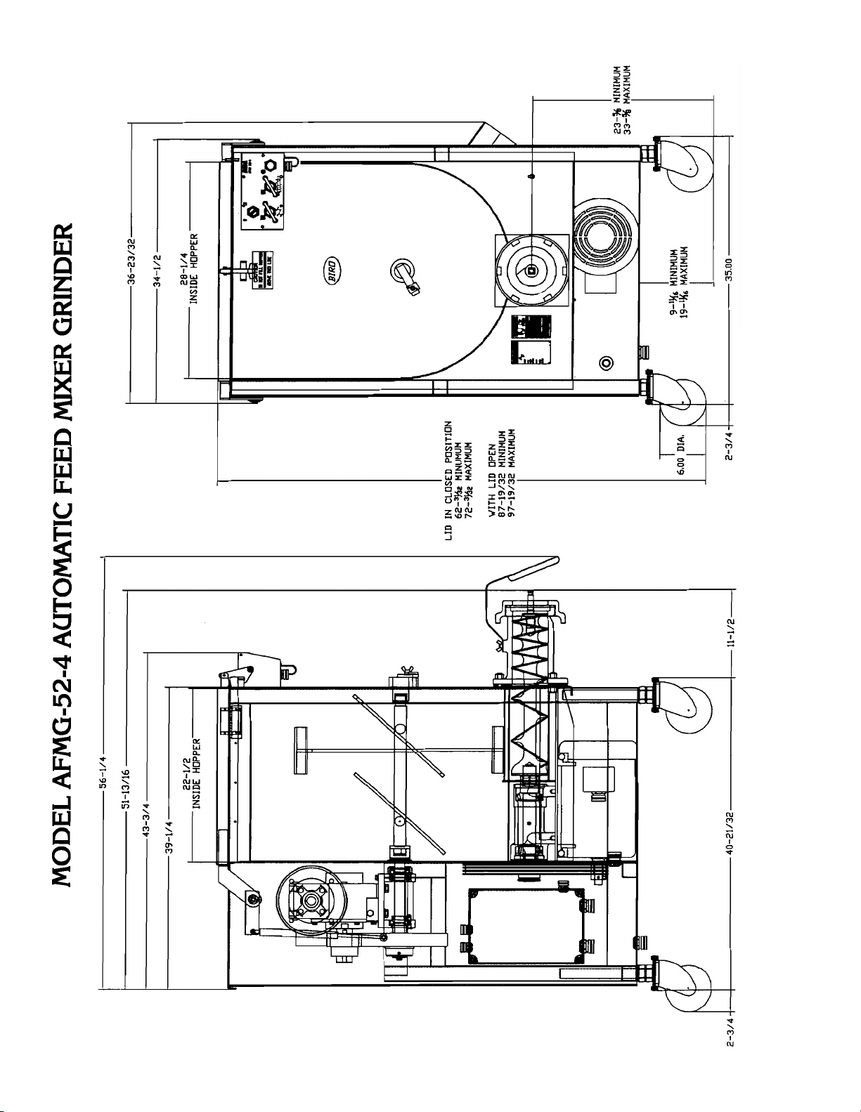
3. This machine is shipped with the adjustable legs fully retracted. The legs allow for a height adjustment from the
floor to centerline of bowl 23
4. This machine weighs approximately 1,302 pounds. To avoid accidents block up machine after raising to desired
operating height.
5. The adjustable legs can now be unbolted and lowered to the floor using the following steps.
a. Unbolt leg and turn leg adjusting nut (Item No. 60120) counterclockwise until caster rests on floor.
b. Retighten lock nuts securely.
6. Install machine on a level, non-skid surface in a well-lighted work area away from children and visitors.
7. This machine is complete except for knife and plate. There is a bowl shipping plug (stamped steel) placed in the
output end of the grinding bowl to retain the grinding auger during shipment. REMOVE THE BOWL SHIPPING
5
" minimum to 33
8
5
" maximum..
8
PLUG AND THE GRINDING AUGER.
8. After checking and making sure the power supply is correct, plug in your machine. NEVER OPERATE THIS
MACHINE WITH PRODUCT MIXER SAFETY COVER OPEN. (Machine will not run with cover open.)
9. Machine must be properly grounded. Use qualified electrician to install according to local building codes.
3
Page 7
MOTOR WIRING AND ELECTRICAL REQUIREMENTS
1. Interchange of current is made in motor outlet box. Leads are properly marked. Changing instructions are on
the motor plate or motor outlet box.
2. All grinders are wired 220 volts unless otherwise specified. Be sure motor specifications (voltage, cycle, phase)
match power supply line. Be sure line voltage is up to specification.
3. Electrical connections to be in accordance with safety codes and National Electrical Code.
4. Rated voltage of the unit shall be identical with full supply voltage.
5. Voltage drop on the supply line shall not exceed 10% of full supply voltage.
6. The feederline conductor size in the raceway from the branch circuit to the unit must be correct to assure
adequate voltage under heavy starting and short overload conditions.
7. The feederline conductor shall only be used for the supply of one unit of the relevant horsepower. For
connections of more than one unit on the same feederline, a local electrician will have to be consulted to
determine the proper conductor size.
8. The size of the electrical wiring required from the power source to the mixer grinder with 10HP grind motor is a
MINIMUM OF No. 6 WIRE.
9. The BIRO Manufacturing Company is not responsible for permanent wiring, connection or installation
NOTE TO OWNER AND ELECTRICIAN: IF THIS MACHINE IS NOT CORD
AND PLUG CONNECTED TO THE ELECTRICAL SUPPLY SOURCE, THEN IT
SHOULD BE EQUIPPED WITH, OR CONNECTED TO, A LOCKABLE,
MANUALLY-OPERATED DISCONNECT SWITCH (OSHA 1010.147).
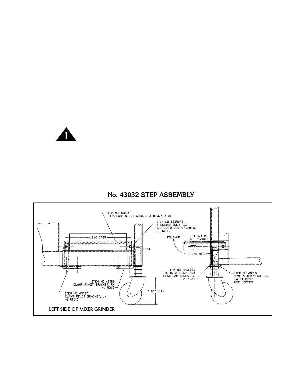
10. Install step assembly Part No. 43032 on grinder's frame cross brace. See diagram below.
4
Page 8

11. Two green and one red pushbuttons are located on the front of the machine that activate the magnetic
contactors that control the mix and grind motors. The magnetic interlock switch is mounted behind the wireway
cover located at the top-side of the hopper. It lines up with the magnet attached to the product mixer safety
cover. When the safety cover is raised the machine will stop operation. Before initial power is applied for
start-up, the product mixer safety cover must be lifted slightly and closed again before pushing the mixer start
and/or grinder start push buttons.
12. Push the green start button for grind. CHECK THE ROTATION OF THE AUGER DRIVE SHAFT; ROTATION
MUST BE COUNTER-CLOCKWISE as indicated by the rotation decal affixed to the grinding bowl. ROTATION
MUST ONLY BE CHECKED WITH THE GRINDING AUGER REMOVED, otherwise serious irreparable damage
may occur to grinding components. Rewire if necessary at the plug.
13. Push the green start button for mix. CHECK ROTATION OF THE MIXING PADDLE; ROTATION MUST BE
COUNTER-CLOCKWISE as indicated by the rotation decal located on the paddle front mounting hub.
Backwards operation will not allow mixing paddle to feed product to the grinding auger.
14. If machine runs clockwise (backwards), it must be rewired to correct rotation, otherwise serious irreparable
damage may occur to grinding components. Both the auger and the mixing paddle must operate in the same
direction.
15. Check operation of optional footswitch if equipped. Plug footswitch cord into fitting at the bottom of the
pushbutton control box. Move toggle selector to foot. The machine will operate with pressure on the footswitch
treadle. Releasing the treadle stops the machine. The footswitch operates the mix and grind together.
16. Insert auger assembly into grinding bowl, place knife (sharp edges out) onto the square end of the auger
assembly. The breaker plate slides over the worm knife drive pin, and is held from rotating by pins in the grinding
bowl. Install the retaining ring.
ONLY HAND TIGHTEN RETAINING RING
For best results, use knife and plate as a set. Do not operate machine for any period of time without product
in the grinding bowl. This will cause heating and dulling of the knife and plate.
17. Check placement of all warning labels and Manual. Machine is now ready for trained operators to process
product.
18. Use meat deflector attached to grinding bowl to eliminate meat splatter.
19. Contact your local Distributor or BIRO directly if you have any questions or problems with the installation or
operation of this machine.
5
Page 9

OPERATION
ROTATING GRINDING AUGER & ROTATING MIXING PADDLE
TO AVOID SERIOUS PERSONAL INJURY
· ONLY Properly Trained Personnel Should Use This Equipment.
· NEVER Place Hands Into Machine Input or Output Openings.
· NEVER Open Machine During Operation.
· DO NOT Wear Gloves While Operating.
· DO NOT Tamper With, Bypass, Alter, or Modify This Equipment in Any Way From Its Original
Condition.
· NEVER Operate Machine With Product Mixer Safety Cover Opened or Removed or Magnetic
Interlock Switch By-Passed.
· ALWAYS Turn Off and Unplug Machine from Power Source and Perform Lockout/Tagout
Procedure to This Machine Before Unjamming, Unclogging, Cleaning or Servicing.
· NEVER Leave Unattended While Operating.
· NEVER Operate Without All Warning Labels Attached and Owner/Operator Manual Available to
the Operator.
A. TO PROCESS PRODUCT
1. Before starting mixer grinder, have a container for receiving ground product at the output end of the grinding
bowl.
2. FIRST GRIND
a. Fill Product Hopper (Maximum 400 Pounds), close Product Mixer Safety Cover.
b. Push both grind and mix green start buttons to feed first grind. It is recommended to use a breaker plate
c. Push the red stop button when all product has been ground out.
3. SECOND GRIND
a. Fill Product Hopper (Maximum 400 Pounds), close Product Mixer Safety Cover.
b. Push the mix green start button only. During this mix operation seasonings may be added through the
c. After the desired mix, push the green grind start button to operate grinding auger and grind out product.
d. Push the red stop button when all product has been ground out.
3
with
" diameter or larger holes.
8
sight holes in the Product Mixer Safety Cover.
4. Unplug from power source and perform lockout/tagout procedures.
6
Page 10

CLEANING
ROTATING GRINDING AUGER & ROTATING MIXING PADDLE
TO AVOID SERIOUS PERSONAL INJURY
· ALWAYS Turn Off, Unplug From Power Source and Perform Lockout/Tagout Procedures to
This Machine Before Cleaning or Servicing.
· ONLY Use Recommended Cleaning Equipment, Materials, and Procedures.
· NEVER Spray Water or Other Liquid Substances Directly at Motor, Power Switch or any Other
Electrical Components.
· ALWAYS Thoroughly Clean Equipment at Least Daily.
CLEANING THE BIRO MIXER GRINDER
1. Disconnect mixer grinder from power source and perform lockout/tagout procedures.
2. Remove grinding bowl end ring, breaker plate, knife and grinding auger.
3. Remove mixing paddle. Be sure front most paddle arm is pointing up. Loosen the thumb screw on the mixer
paddle lock arm (Item No. 53852). While supporting the mixing paddle, remove the lock arm. Turn the mixing
paddle counterclockwise, slide forward to disengage from drive shaft and lift from product hopper.
DO NOT POWER SPRAY DIRECTLY AT ELECTRICAL COMPONENTS
4. Machine is now ready to be cleaned using warm soapy water and rinsed with clean water. Machine may be
cleaned by power spray washing, taking care to not spray directly at any electrical controls.
5. The grinding head can be removed for cleaning if desired. This is accomplished by removing the three nuts on
the back flange of the grinding head.
6. After machine has been cleaned and allowed to dry, all exposed metal surfaces should be coated with a good
food grade light oil or grease.
CLEANING THE BOWL - RING AND WORM
CARE OF TIN COATED PRODUCTS
(DO’S AND DON’TS)
1. Do not use abrasive cleaning materials, such as brillo pads or metal scrapers. Tin is a soft metal and
should be cleaned with a soft cloth and dried.
2. Do not use a cleaning agent containing a high percentage of free alkali or acid.
3. Do not use a detergent containing a high percentage of tri-sodium phosphate or meta-silicate.
Tin is reactive to both.
4. Rinse well and dry throughly after washing to remove agents that may be reactive to tin.
5. If sterilizing agent containing chlorine is used, the tinned surface must be throughly rinsed.
Chlorine is corrosive to tin.
6. Dry throughly after rinsing and store in a dry environment.
7. If water is exceptionally hard, drying will be necessary to prevent spotting.
7
Page 11

MAINTENANCE
ROTATING GRINDING AUGER & ROTATING MIXING PADDLE
TO AVOID SERIOUS PERSONAL INJURY
· ALWAYS Turn Off, Unplug from Power Source and Perform Lockout/Tagout Procedures to
This Machine BEFORE Servicing.
· NEVER Touch This Machine Without Training and Authorization By Your Supervisor
· NEVER Place Hands Into Machine Input or Output Openings.
· NEVER Bypass, Alter or Modify This Equipment in Any Way From Its Original Condition.
· PROMPTLY REPLACE Any Worn or Illegible Warning Labels.
· USE ONLY GENUINE BIRO Parts and Accessories Properly Installed.
A. GRINDING BOWL INSTALLATION
1. Mount the grinding bowl on the three threaded studs on the front of the machine. Tighten in position with
provided nuts.
2. Place the grinding auger in the grinding bowl and fully seat rear drive tang into auger drive shaft.
3. Install knife, breaker plate and end retaining ring.
ONLY HAND TIGHTEN RETAINING RING
4. When the bowl assembly is mounted and tight, there should be approximately
inside wall of the grinding trough and the back of the auger. The bowl ring wrench which is provided with
each mixer grinder is used only for REMOVAL of the end retaining ring for cleaning purposes or for changing
knife and breaker plate.
1
" gap between the back
8
B. MIXING PADDLE INSTALLATION
1. Holding the mixing paddle by the center shaft and with the front blade up carefully fit drive male collar into
the end of the drive shaft. Insert paddle lock arm assembly (Item No. 53852) into the front of the mixing tub
and onto the front of the mixing paddle.
2. When fully seated, turn the lock arm counterclockwise so the protruding arm is behind the lock set screw
bracket. Tighten the mixer paddle lock set screw (Item No. 53568).
C. LUBRICATION
1. MOTORS: The mix and grind motors have pre-lubricated bearings. These bearings should be re-lubricated
annually with a good grade of bearing grease. Do not over-grease.
2. BEARING HOUSING: The main bearings are housed in an enclosed and sealed journal box. Re-lubricate
semi-annually with a good grade of bearing grease. Do not over-grease. This may cause seal damage.
8
Page 12

No. 60027 WINSMITH GEAR REDUCER
LUBRICATION AND MAINTENANCE
VIEW IS FROM OPPOSITE SIDE OF DRIVEN SHAFT
LUBRICANTS FOR WORM GEAR REDUCERS
The precision-made gears and bearings in Speed Reducers require high-grade lubricants of the proper viscosity to
maintain trouble-free performance. For best results, use lubricants on the following chart for worm gear reducers.
MINERAL OILS SYNTHETIC OILS
Ambient Temperature 16 to 50ºF 96 to 131ºF
Final State Worm Speed Up to 2000 FPM Up to 450 FPM
ISO Viscosity Grade 460 680
AGMA Lubricant No. #7 Compounded 8 S
Mobil 600W Super Cylinder SHC 636
American Lubricants AGMA #7 Gear Oil N/A
Castrol Tribol 1105-7C Tribol 800/680
Chevron Cylinder Oil W460 Tregra 680
Conoco Inca Oil 460 N/A
Exxon (Esso) Spartan EP 460 Teresstic SHP 680
Fiske Brothers SPO-277 N/A
Shell Valvata J 460 Omala RL 680
Texaco Vanguard 460 Pinnacle 680
Standard factory-installed lubricant is Mobil Oil Corp. 600 W Super Cylinder Oil (AGMA7).
Some gear lubricants contain E.P. additives that can be corrosive to gear bronze material. Avoid lubricants that are
compounded with sulfur and/or chlorine.
Lubricant selections are provided by the lubricant manufacturer based on AGMA recommended viscosity grades. Vis
cosity grades are based on Lubrication Standard ANSI/AGMA 9005-D94.
9
-
Page 13

LUBRICATION (Cont.)
1. Factory Filling
The speed reducers are filled with Mobile 600W Super Cylinder oil at the factory to the proper level for the
standard mounting position. The oil level should be checked and adjusted (if necessary) prior to operation,
using the oil level plug provided and while the unit is oriented in its operating position.
2. Oil Changing
When changing oil for any reason, It should be remembered that oils of various types may not be compatible.
Therefore, when changing to a different oil, it is recommended that the housing be completely drained and
thoroughly flushed with a light flushing oil prior to refilling with the appropriate lubricant. The oil level should
be rechecked after a short period of operation and adjusted, if necessary.
A. Initial Oil Change
Oil in the mixer transmission should be changed after the first four (4) weeks of operation. This is to
remove the initial oil and also any small metal shavings that may have been generated during the mating
of the gears.
B. Subsequent Oil Changes
After the initial oil change, subsequent changes should be performed every six (6) months. After draining
the oil, refill the unit to the "level" plug on the side of the transmission with Mobil 600W Super Cylinder oil
or equivalent.
C. Synthetic Oils
Synthetic lubricants can be advantageous over mineral oils in that they generally are more stable, have a
longer life, and operate over a wider temperature range. These oils are appropriate for any application but
are especially useful when units are subjected to low start-up temperatures or high operating
temperatures. However, continuous operation above 225ºF may cause damage to seals or other
components. It is recommended that the initial oil be changed or filtered after the first 1500 hours of
operation to remove metal particles that accumulate during break-in. Subsequent oil changes should be
made after 5000 hours operation if the units are operating in a clean environment. This can be extended
to 10,000 hours if using new reformulated Mobile SHC 636 lubricants
remains free of contamination over this period.
(orange in color) and the lubricant
3. PROCEDURE FOR REPLACING OIL IN MIXER TRANSMISSION
a. Unplug mixer grinder from power source and perform lockout/tagout procedures.
b. Remove rear drive cover or access cover.
c. Remove vent plug on the top side of the gearbox and the oil level plug from the side of the gearbox.
d. With a container in place to catch old oil, remove the lower drain plug on the side of the gearbox.
e. When all oil has drained, clean the drain plug and re-install in the gearbox.
f. Refill the gearbox with Mobil 600W Super Cylinder oil or equivalent until oil appears at the bottom of the
oil level hole. Approximately 3.1 pints
g. Replace oil level and vent plugs.
h. Reinstall rear drive cover or access cover.
4. Overfilling or Underfilling
If a speed reducer is overfilled with oil, the energy used in churning the excessive oil can result in overheating.
If this occurs, shut down the drive, remove the oil level plug and allow oil to drain until oil ceases to drain
from the level hole, reinstall the oil level plug and restart the drive. if the speed reducer is underfilled, the
resultant friction can cause overheating and possible damage. If this occurs, fill the speed reducer to the oil
level plug hole and check the gearing for excessive wear.
5. Oil Seals
Although the speed reducer uses high quality oil seals and precision ground shafts to provide a superior seal
contact surface, it is possible that circumstances beyond the speed reducer's control can cause oil seal
leakage (damage during shipment or installation, etc.). When replacing a shaft oil seal, using the following
suggestions will help to insure leak-free operation and long seal life.
A. When installing a new seal, cover the keyway and any other surface discontinuity with smooth tape to
protect the seal lip from being damaged.
B. A sealant should be used between the O.D. of the seal and the I.D. of the bore into which the seal is
installed. The seal bore should also be free of any burrs, nicks, or scratches.
C. Be sure that the seal is not cocked in the seal bore. The outer face of the seal should be flush with the
surface into which it is mounted.
of oil
10
Page 14

D. SPUR GEARS LUBRICATION
Gears should be checked after the first two weeks of operation. Then every 6 weeks, depending on hour's
used or severe duty every 2 weeks. Recommended types of spur gear lubricant are those with Lithium soap
base. Also bonded lubricants such as Shell Cassida EPS Grease 2 or equivalent for Spur Gears. The
lubricant should be of a viscosity whereby it will stick and bond to the working surfaces to reduce heat and
wear to the Spur Gear Teeth.
a. Unplug mixer grinder from power source and perform lockout/tagout procedures.
b. Remove rear drive cover or access cover.
c. Spray or brush lubricant on teeth of the Spur Gears complete.
d. Reinstall rear drive cover.
E. MIXER DRIVE GEAR ADJUSTMENT
Unplug mixer/grinder from power source and perform lockout/tagout procedures.
Remove rear drive cover.
Loosen the four bolts and adjustment bolt holding the 5 hp motor and transmission to its mounting plate.
Slide Mixer Transmission to the right.
When the Spur Gears are interlocked leave a little clearance, about
Do Not Bottom Out the Gear Teeth into the Other Driven Gear.
This will put excessive and damaging pressure on the transmission bearings and mixer drive shaft bearings.
Check with a straight edge from the large spur gear across the face to the face of drive spur gear in two
different locations. The spur gears must be aligned. Tighten the adjustment bolt up to the transmission and
tighten jam nut. Tighten the four bolts to the transmission and mounting plate. Check the spur gear
alignment again. See Lubrication.
1
1
"–
".
64
32
Reinstall rear drive cover.
F. MAIN DRIVE CHAIN AND SPROCKET LUBRICATION:
The main drive chain has been pre-lubricated at the factory to protect it against dirt and moisture. Chain life
will vary appreciably depending upon its lubrication. The better the lubrication, the longer the chain life.
Lubrication effectiveness will vary with the amount of lubricant and frequency of application. Ideally, a
lubricant film should always be present between the working parts. Manually lubricate the chain as often as
is needed (possibly once a week). NEVER
Lubricating just the outside of the chain does little good. Apply lubrication on the inside of the chain span so
that it will work through the moving parts and joints by centrifugal force as the chain rotates and reaches the
area where one surface “scrubs” another.
Recommended types of chain lubricant are those with Molybdenum Disulphide or Graphite added. Also
bonded lubricants such as Dow Corning Molykote 321R or equivalent are excellent for open chains. The
lubricant should be of a viscosity whereby it will “flow” somewhat and penetrate the internal working surfaces.
Thick stiff greases are of little value because they cannot work into the moving parts of the chain.
a. Unplug mixer/grinder from power source and perform lockout/tagout procedures.
b. Remove rear drive cover.
c. Spray or brush lubricant on inside of chain, slowly and carefully turning large sprocket by hand.
d. Reinstall rear drive cover.
exceed three months without lubricating.
11
Page 15

G. MAIN DRIVE CHAIN TENSION (See Diagram Below)
1. Unplug mixer/grinder from power source and perform lockout/tagout procedures.
2. Remove rear drive cover.
3. Loosen the four bolts that hold the motor to the frame of the machine.
4. Loosen the lock nuts on the motor adjusting stud.
5. To Loosen Chain Tension. Turn motor adjusting studs counterclockwise. Grasp motor and pull toward
adjusting stud. Be sure to turn both adjusting studs the same amount and evenly. Total chain flex should be
1
3
"to
". Be sure to keep motor shaft parallel with auger drive shaft.
8
8
To Tighten Chain Tension. Turn motor adjusting studs clockwise. Be sure to turn both adjusting studs the
same amount and evenly. Total chain flex should be
excessive and damaging pressure on the motor bearings. Be sure to keep motor shaft parallel with auger
drive shaft. Be sure the sprockets are inline.
6. Retighten motor mounting bolts.
7. Retighten motor adjusting stud lock nuts.
8. Reinstall the rear drive cover.
1
3
"to
". Do not overtighten chain as this will put
8
8
H. CHAIN REPLACEMENT
1. Part No. H384-CL Service Replacement Chain is provided with a
"Connecting Link" (Part No. H384-LINK) so that is can be separated
to facilitate installation over the sprockets
Upon assembly, be sure the connecting link is installed so the spring
clip is orientated with its opening facing "opposite" the direction of the
chain travel (See Diagram). â
12
AFTER INSTALLATION
THE CHAIN SHOULD BE
TENSIONED TO
APPROXIMATELY
1
3
to
FLEX
8
8
Page 16

AFMG-52-4 FRONT VIEW PARTS DIAGRAM
13
Page 17

AFMG-52-4 FRONT VIEW PARTS LIST
Fig. Item No. Description
1 53687 Decal, Do Not Fill Above This Line
2 RHS31S ¼-20
3 56072 Safety cover latch
4 HNNL15S ¼-20 heavy nylok nut
5 43015 Safety cover, 400 lb. 52 hopper
6 PC168 Safety switch
7 PC169 Safety switch magnet
8 52655 Female receptacle, footswitch
9 52662 Protective cap assembly
10 57023-CTN Bowl w/plate pins
11 HR52 Ring
12 54303 Outer disc, double rod
13 14688 4 point knob,
14 53715 Ring wrench hanger
15 FW05S ¼ flat washer, S.S.
16 LW10S ¼ lock washer, S.S.
17 HN15S ¼-20 hex nut, S.S.
18 HK52/56 Knife drive pin
19 57022-CTN Auger assembly
20 HN68S 1¼-7 hex nut, S.S. (4 req'd.)
21 60120 Foot assembly, caster, (4 req'd.)
22 HHS070S
23 FW16S
24 AN20S
3
8
5
16
3
8
25 60123 Swivel caster w/slide lock (4 req'd.)
26 57025 Motor, 10HP, 208/230/460V/60HZ/3Ph
27 57025-5 Motor, 10HP, 575V/60HZ/3Ph
28 57103-SOW Cord grip connector, 1.00,
29 57103-1 Lock nut, strain relief, 1.00
30 H653-E Grinder warning label, English
31 H653-SP Grinder warning label, Spanish
32 53568 Mixer paddle lock set screw
33 53852 Lock arm assembly w/bearings
34 VTS7181 Biro world decal
35 52357 Ring wrench (order H340)
¾ round head screw
´
3
-16 thread (2 req'd.)
8
-16´1.00 hex head screw, S.S., (16 req'd.)
(.380 ID) flat washer, S.S., (32 req'd.)
-16 acorn nut, S.S., (16 req'd.)
7
-1.00 (5 req'd.)
8
NOT SHOWN
VT460S Model/serial no. plate
T3059-2-1A Pop rivet, (12 req'd. for all tags)
43040 Side inlet seal, double rod, 35 degree
14
Page 18

AFMG-52-4 SIDE VIEW PARTS DIAGRAM
15
Page 19

AFMG-52-4 SIDE VIEW PARTS LIST
Fig. Item No. Description
1 43015 Safety cover, 400 lb. 52 hopper
2 PC168 Safety switch
3 PC169 Safety cover magnet
4 HHS040S ¼-20
5 AN15S ¼-20 acorn nut
6 56072 Safety cover latch
7 43020 Mixer paddle assembly, 2
8 53852 Lock arm assembly w/bearings
9 53568 Mixer paddle lock set screw
10 HN40S ½-13 hex nut, S.S. (1 req'd.)
11 53413 ½-13
12 WN20S
3
8
13 52392 Meat guard splash shield
14 HK52/56 Knife drive pin
15 HR52 Ring
16 57022-CTN Auger assembly
17 57023-CTN Bowl w/plate pins
18 53413-2 ½-13
19 HN40S ½-13 hex nut, S.S. (4 req'd.)
20 HN68S 1¼-7 hex nut, S.S. (4 req'd.)
21 HHS070S
22 FW16S
23 AN20S
3
8
5
16
3
8
24 60123 Swivel caster w/slide lock (4 req'd.)
25 HHS100S
3
8
26 57103-SOW Cord grip connector, 1.00,
27 57025 Motor, 10HP, 208/230/460V/60HZ/3Ph
28 57025-5 Motor, 10HP, 575V/60HZ/3Ph
29 57103-SOW Cord grip connector, 1.00,
30 57103-1 Lock nut, strain relief, 1.00 (5 req'd.)
31 60120 Foot assembly, caster (4 req'd.)
32 224-4 Cord grip connector, ½, .625-.750
33 224-1N Conduit nut, ½ (3 req'd.)
34 224-5 Cord grip connector, ½, .375-.500
35 14672 Cord grip connector, multiple hole
36 PC166 Rear cover safety switch
37 40426 Driven gear, 60 teeth
38 EMG62062-1 Ball stud, gas spring (2 req'd.)
39 40425 Drive gear, 20 teeth
40 EMG62190 Gas spring, internal (2 req'd.)
41 EMG62062-1 Ball stud, gas spring (2 req'd.)
42 40444 Lid damper arm, right hand
¾ hex head screw, S.S.
´
nd
grind
1.75 bowl mounting stud (1 req'd.)
´
-16 wing nut, S.S.
2.375 bowl mounting stud (2 req'd.)
´
-16´1.00 hex head screw, S.S., (16 req'd.)
(.380 ID) flat washer, S.S., (32 req'd.)
-16 acorn nut, S.S., (16 req'd.)
-16 6.00 hex head screw (2 req'd.)
7
-1.00
8
7
-1.00 (5 req'd.)
8
NOT SHOWN
43010 Rear cover
PC084 Safety switch magnet
16
Page 20

AFMG-52-4 BACK VIEW PARTS DIAGRAM
17
Page 21

AFMG-52-4 BACK VIEW PARTS LIST
Fig. Item No. Description
1 43015 Safety cover, 400 lb. 52 hopper
2 40426 Driven gear, 60 teeth
3 PC166 Back panel safety switch
4 224-5 Cord grip connector, ½, .375-.500
5 224-1N Lock nut, strain relief
6 40448 Watertight electrical enclosure
7 HHSM048S M6
8 57103-SOW Cord grip connector, 1.00,
9 HN68S 1¼-7 hex nut, S.S. (4 req'd.)
10 HHS070S
11 FW16S
12 AN20S
3
-16´1.00 hex head screw, S.S. (16 req'd.)
8
5
16
3
-16 acorn nut, S.S. (16 req'd.)
8
13 60123 Swivel caster w/slide lock (4 req'd.)
14 53727 Main sprocket, 141 teeth
15 H484-CL Roller chain w/connecting link
16 57025 Motor, 10HP, 208/230/460V/60HZ/3Ph
17 57025-5 Motor, 10HP, 575V/60HZ/3Ph
18 H382-1 Motor pinion, 22 teeth
19 54303 Outer disc, double rod
20 14688 4 point lock knob,
21 43040 Side inlet seal, 35 degree, double rod
22 224-3 Cord grip connector, ½, .625-.750
23 57103-1 Lock nut, strain relief
24 PC168 Safety switch
25 PC169 Safety switch magnet
35mm hex head screw (4 req'd.)
´1´
7
-1.00 (5 req'd.)
8
(.380 ID) flat washer (32 req'd.)
3
-16 thread (2 req'd.)
8
NOT SHOWN
43010 Rear cover
PC084 Safety switch magnet
18
Page 22

AFMG-52-4 MIXER DRIVE ASSEMBLY
Fig. Item No. Description
1 60028 Mixer motor, 5HP, 208-230/460V/3PH/60Hz
2 60027 Mixer transmission, 25:1 ratio
3 40425 Drive gear, 20 tooth spur gear
4 60029 Key, mixer drive gear–½sq.
3"
´
5 40426 Driven gear, 60 tooth spur gear
6 60030 Key, mixer driven sprocket
7 HHS070S Hex head cap screw,
8 HHS083S Hex head cap screw,
9 LW20S Lock washer,
10 FW07S Flat washer,
3
8
3
stn. stl.
8
3
3
stn. stl.
-16 UNC´1" stn. stl.
8
-16 UNC´1¾" stn. stl.
8
11 43009 Bearing mounting plate rear, paddle drive shaft
12 HHS136S Hex head cap screw, ½-13 UNC
3" stn. stl.
´
13 HN42S Hex nut, ½-13 UNC stn. stl.
14 60043 Spacer, driven spur gear
15 60041 Spacer, paddle drive shaft brg. mnt. plate
16 43008 Bearing mounting plate front, paddle drive shaft
17 60024 Cap, front bearing mtg. plate
18 60047 Paddle drive shaft, LH female
19 60054 Bearing, 1¼ bore single row ball bearing
20 60042 Locking collar, 2 pcs.
21 60050 Washer, paddle drive shaft
22 53953 Seal, mixer drive shaft
stn. stl.
stn. stl.
5
-11 UNC´2" stn. stl.
8
3
-16 UNC´1¾" stn. stl.
8
3
-16 UNC´1¾" stn. stl.
8
3
-16 UNC´1½" stn. stl.
8
1½" stn. stl.
´
23 HHS147S Hex head cap screw,
24 LW35S Lock washer,
25 FW17S Flat washer,
5
8
5
8
26 HHS083S Hex head cap screw,
27 HHS083S Hex head cap screw,
28 SHS080S Socket head cap screw,
29 HHS127S Hex head cap screw, ½-13 UNC
19
Page 23

LID HINGE COMPONENTS
Fig. Item No. Description
1 40445 Lid damper arm, left hand
2 40444 Lid damper arm, right hand
3 EMG62062-1 Ball stud, gas spring (4 req'd.)
4 LW15S
5 HNNL25S
6 HHS083S
5
lock washer (4 req'd.)
16
3
-16 Nylock hex nut (2 req'd.)
8
3
-16´1¾ hex head screw (2 req'd.)
8
7 EMG92032 Washer, outside lid hinge arm (2 req'd.)
8 EMG62184 Washer, outside lid hinge arm (2 req'd.)
9 EMG62182 Sleeve bushing, hinge (2 req'd.)
10 EMG62181 Washer, inside lid hinge (2 req'd.)
11 EMG62190 Gas spring, internal (2 req'd.)
12 EMG62190-1 Retaining clip for gas spring (4 req'd.)
20
Page 24

No. 53886 JOURNAL BOX ASSEMBLY
Item No. Description
53609 Journal box, serial no. 62001 on
53724 Auger drive shaft, serial no.
62001 on
53785 Journal box seal (2 ea.)
53886 Journal box assembly complete
Item No. Description
53888, 53940 Front bearing cup/cone assembly
Order H310A
53889, 53939 Rear bearing cup/cone assembly
Order H311A
53993 Vented grease fitting
130mm UNGER
Item No. Description
FHS36S Shear pin fastener ¼-20´1SS
HHS012S Hex head screw, 10-32
HK130 Knife drive pin, 130mm Unger
HR52S End ring, SS
LW05S Lock washer, #10, SS
54278C Auger shear pin
57022S-130 Auger assembly, SS, 130mm
Unger
57023S-130 Bowl, SS, 130mm Unger
57023K-130 Key, 130mm Unger
1
,SS
´
2
ENTERPRISE
Item No. Description
HR52S End ring, SS
57022S Auger assembly, SS
57023S Bowl, SS
21
Page 25

AFMG-52-4
PUSHBUTTON PLATE COMPONENTS
Fig. Item No. Description
1 EMG90668 Selector switch, 2 position hand/foot
2 H462-1 Trim ferrule – 4 req'd.
3 50655-1 Switch guard – 2 req'd.
4 LW15S
5 HN20S
5
lock washer – 4 req'd. (opposite side, not shown)
16
5
-18 hex nut – 4 req'd. (opposite side, not shown)
16
6 42MC-Y73 Start switch, mixer
7 42MC-Y73 Start switch, grinder
8 52655 Female receptacle, footswitch
9 52662 Protective cap assembly
10 42MC-Y74 Stop switch, all
11 43014 Front cover, pushbutton enclosure
22
Page 26

AFMG-52-4 ELECTRICAL COMPONENT ASSEMBLY
Fig. Item No. Description
1 43037 Contactor LS18K, 24 VAC coil
(208-460V)
2 57027-AE-CE Contactor LS22K 11-GO, 24 VAC coil
(208-240V)
2 43037 Contactor LS18K, 24 VAC coil
(440-460V)
3 BLK323 End barrier
PC162 Central control unit
4
5 EMG92014 Fuse block
6 EMG90552 Fuse, 3 amp, time delay
7 PC152 Terminal, 7 req'd.
8 PC257 Internal jumper
9 BLK322 Ground block terminal
10 60053 Din rail, 5
11 THS018S #10-32
5
"
8
3
" truss head screw, stn. stl.
´
8
12 RHS075-ST Round head self tap screw 10-16´½,
stn. stl.
13 60051 Subplate
14 PC141-1 Transformer, 200/208/240-460-24VAC
SEC
15 EMG90179 Buss link – fits LS22K, 30K, 37K
(BL-283) 208-240V
Fig. Item No. Description
15 EMG90249 Buss link – fits LS18K (BL-284)
16 H281AE-330 Overload, 22-32 amp, B77S 20-32A
16 H281AE-31 Overload, 11-17 amp, B27T-N 11-17A
17 RHS10S 10-32
18 FW04S #10 flat washer, stn. stl.
19 HHS040S ¼-20´¾" hex head cap screw, stn.
20 LW10S ¼ lock washer, stn. stl.
21 HN15S ¼-20 hex nut, stn. stl.
22 60103 Grounding block
23 H281AE-31 Overload B17S-N or B27T-N 11-17A
440-480V
(208-240V
)
(440-460V)
¾" round head screw, stn. stl.
´
stl.
(208-240V) same as 226 AE-OL17N
23 226AE-OL08L Overload B27T-L 5.6-8A
(440-460V)
24 60052 Din rail, 4¼"
25 EMG90194 Aux. contact, N.O., – 1 req'd.
26 VTS582 End plate, terminal block
23
Page 27

24
Page 28

25
Page 29

ELECTRIC FOOT SWITCH ASSEMBLY No. 52668/54213
Assembly No. 56304
LW03S
Page 30

27
Page 31

CONNECTION INSTRUCTIONS
TANDEM OPERATIONS
AFMG-48 or AFMG-52 INTO AFMG-48 or AFMG-52
Heavy Horsepower Grinder INTO AFMG-48 or AFMG-52
Remove Side Entrance Seal, Item No. 43040; Outer Disc, Item No. 54303 and
Lock Knobs, Item No. 14688 from the inlet tube of the Second Grind Machine.
Clean out the tube if necessary.
Install the Inlet Tube Seal Item No. 53671 or 57145
into the inlet tube of the Second Grind Machine until
fully seated.
Remove the Ring from the First Grind Machine, Item No. HR42.48 or HR52. Insert the Discharge Horn, Item No. 57144-7 or 57143-7 into the ring. (DO NOT
reinstall the ring on the First Grind Machine at this time.) Slide the Clamp Assembly, Item No. 57144-11 or 57143-11 onto the Discharge Horn.
Insert the Discharge Horn with Ring and Clamp Assembly
into the Seal, pushing it fully against the inlet tube internal
fins. Attach the lock latches to the tabs on the side of the
inlet tube and lock down. Tighten the lock knob on the
Clamp Assembly.
Move the Discharge Horn of the Second Grind Machine up to the Bowl of the First
Grind Machine. With the Auger, Knife and Grinding Plate installed in the First
Grind Machine, thread the Ring onto the First Grind Machine Bowl. RING
SHOULD BE HAND TIGHTENED ONLY: USE NO TOOLS.
28
Page 32

TANDEM OPERATION
PARTS LIST
272-7-1
53489 Dscg. Horn 24/42/46/48 to 24/48/52
57044 Connec. brkt. AFMG52 to AFMG48
57044 Connec. brkt. AFMG52 to AFMG52
53552-1A Connecting brkt. assem. man/auto
53604 Dscg. horn 52 to 24/48/52 inlet
53667 Dscg. horn 56 to 24/48/52 inlet
53671 Seal only 24/42/46/48 to 24/48/52
53673 Disc. horn 48-52 w/seal
53933 Seal only 52/56 to 24/48/52 inlet
5
-18 plastic knob, 3 pt.
16
inlet less seal
inlet
29
Page 33

30
Page 34

SAFETY LABEL LOCATIONS
CAUTION
KEEP HANDS OUT OF HOPPER
31
Page 35

OPERATOR'S SIGNATURE PAGE
WARNING
READ AND UNDERSTAND THIS ENTIRE
MANUAL BEFORE SIGNING BELOW
MY SIGNATURE ATTESTS THAT I HAVE COMPLETELY READ AND UNDERSTAND THIS
MANUAL. I REALIZE THAT THIS MACHINE, IF OPERATED CARELESSLY, CAN CAUSE SERIOUS INJURY TO MYSELF AND OTHERS.
NAME (PRINT) SIGNATURE
SUPERVISOR'S
INITIALS
DATE
32
Page 36

LIMITED WARRANTY
WARRANTY: The Biro Manufacturing Company warrants that the BIRO AFMG-52-4 Mixer
Grinder/Chopper will be free from defects in material and workmanship under normal use and with
recommended service. BIRO will replace defective parts, which are covered by this limited warranty, provided that the defective parts are authorized for return, shipping charges prepaid, to a
designated factory for inspection and/or testing.
DURATION OF WARRANTY: The warranty period for all parts covered by this limited warranty is
one (1) year from date of inspection/demonstration as advised on the returned Warranty registration card, or eighteen (18) months from original factory shipping date, whichever date occurs first,
except as noted below.
PARTS NOT COVERED BY WARRANTY: The following are not covered by this limited warranty:
wearable parts in the grinding system such as bowl, ring, worm, drive shaft, and knife drive pin.
This limited warranty does not apply to machines sold as used, rebuilt, modified, or altered from
the original construction in which the machine was shipped from the factory. Water contaminated
electrical systems are not covered under this limited warranty. BIRO is not responsible for electrical connection of equipment, adjustments to the switch controls or any other electrical requirements, which must be performed only by a certified electrician. BIRO is not responsible for service
charges or labor required to replace any part covered by this limited warranty or for any damages
resulting from misuse, abuse, lack of proper or recommended service.
EXCLUSION OF WARRANTIES AND LIMITATION OF REMEDIES: BIRO gives no warranties
other than those expressly stated in this limited warranty. THE IMPLIED WARRANTY OF MERCHANTABILITY, THE IMPLIED WARRANTY OF FITNESS FOR PROCESSING OF FOOD PRODUCTS, AND ALL OTHER IMPLIED WARRANTIES ARE SPECIFICALLY EXCLUDED. BIRO IS NOT
LIABLE FOR CONSEQUENTIAL OR INCIDENTAL DAMAGES, EXPENSES, OR LOSSES. THE
REMEDIES PROVIDED IN THIS BIRO LIMITED WARRANTY ARE PURCHASER’S SOLE AND EXCLUSIVE REMEDIES AGAINST BIRO.
REGISTRATION CARDS: You must sign, date and complete warranty registration card supplied
with each machine. The warranty card must be returned to The Biro Manufacturing Company for
proper registration. If no warranty card is returned to BIRO, the warranty period will begin from
the date the machine was originally shipped from the factory.
HOW TO GET SERVICE:
1. Contact the entity from whom you purchased the machine; or
2. Consult the yellow pages of the phone directory for the nearest authorized dealer; or
3. Contact BIRO Mfg. Company for the authorized service entity (250 plus worldwide) in your area.
THE BIRO MANUFACTURING COMPANY
THE BIRO MANUFACTURING COMPANY
1114 Main Street
1114 Main Street
Marblehead, Ohio
Marblehead, Ohio 43440-2099
Ph. 419-798-4451
Ph. 419-798-4451
Fax 419-798-9106
Fax 419-798-9106
E-mail: Service@birosaw.com
E-mail: service@biro saw.com
Web: http://www.birosaw.com
Web: http://www.birosaw.com
ITEM NO: 43043
ITEM NO: 43043
PTCT AFMG 52-4-332-5-06-1 COMM
PTCT AFMG 52-4-332-9-07-2 ACME
33
 Loading...