

Page 1
+
IMPORTANT NOTICE
+
This Manual contains important
safety instructions which must
be strictly followed when using
this equipment.
AFMG-48
138-9-05-12
AFMG-48
138-4-08-13
Page 2

— NOTES —
Page 3

TABLE OF CONTENTS
Page
NOTICETOOWNERSANDOPERATORS......................................... 1
SAFETYTIPS............................................................... 2
INSTALLATION ............................................................. 3
UNCRATINGANDSETUP................................................ 3
MOTOR WIRING AND ELECTRICAL REQUIREMENTS . . . . . . . . . . . . . . . . . . . . . . . . . . 4
MOTORSPECIFICATIONS ............................................... 4
OPERATION................................................................ 6
TOPROCESSPRODUCT ................................................ 6
CLEANING................................................................. 7
MAINTENANCE ............................................................. 8
GRINDINGBOWLINSTALLATION ......................................... 8
MIXINGPADDLEINSTALLATION.......................................... 8
LUBRICATION.................................................... 8,9,10
NORD TRANSMISSION MAINTENANCE & LUBRICATION . . . . . . . . . . . . . . . . . . . . . . . . 9
DORRIS TRANSMISSION MAINTENANCE & LUBRICATION . . . . . . . . . . . . . . . . . . . . . . 10
MIXERDRIVEBELTTENSION.............................................10
MAIN DRIVE CHAIN AND SPROCKET LUBRICATION . . . . . . . . . . . . . . . . . . . . . . . . . . 10
MAINDRIVECHAINTENSION.............................................11
CHAINREPLACEMENT..................................................11
WIRINGDIAGRAMS ..........................................................12
NOTES....................................................................13
PARTSDIAGRAMS.....................................................14,15,16
OPTIONAL STAINLESS STEEL BOWLS, AUGERS & END RINGS
(114mmUNGER&ENTERPRISE)..........................................15
PRODUCTMIXERSAFETYCOVERS&LIDLOCKS ............................17
DORRISMIXERTRANSMISSIONPARTSLIST.................................18
JOURNALBOX........................................................19
ELECTRICFOOTSWITCH................................................19
ITEMS REQUIRED FOR TANDEM OPERATION TO S/N 63591 . . . . . . . . . . . . . . . . . . . . . . 20,21
ITEMS REQUIRED FOR TANDEM OPERATION AFTER S/N 63592 . . . . . . . . . . . . . . . . . . . 22,23
CONNECTION INSTRUCTIONS FOR TANDEM OPERATION . . . . . . . . . . . . . . . . . . . . . . . 23,24
SAFETYLABELLOCATIONS...................................................25
OPERATOR'SSIGNATUREPAGE................................................26
NOTES....................................................................27
LIMITEDWARRANTY.........................................................28
PARTS DIAGRAMS ....................................................13, 14, 15
PRODUCT MIXER SAFETY COVERS & LID LOCKS
STANDARD & OPTIONAL STAINLESS STEEL BOWLS,
AUGERS & END
RINGS (114mm UNGER & ENTERPRISE..................17
........................ 16
Page 4

— NOTES —
Page 5
BIRO’s products are designed to process food products safely and efficiently. Unless the operator is properly trained and supervised, however, there is the possibility of a serious injury. It is the
responsibility of the owner to assure that this machine is used properly and safely, strictly following
the instructions contained in this Manual and any requirements of local law.
No one should use or service this machine without proper training and supervision. All operators should be thoroughly familiar with the procedures contained in this Manual. Even so, BIRO
cannot anticipate every circumstance or environment in which its products will be used. You, the
owner and operator, must remain alert to the hazards posed by the function of this equipment —
particularly the ROTATING GRINDING AUGER and the ROTATING MIXING PADDLE, which can
severely injure an inattentive operator amputating fingers and limbs. No one under eighteen (18)
years of age should operate this equipment. If you are uncertain about a particular task, ask your
supervisor.
This Manual contains a number of safe practices in the SAFETY TIPS section. Additional warnings are placed throughout the Manual. Warnings related to your personal safety are indicated by:
Warnings related to possible damage to the equipment are indicated by:
BIRO also has provided warning labels on the equipment. If any warning label or Manual becomes misplaced, damaged, or illegible, please contact your nearest Distributor or BIRO directly
for a replacement.
Remember, however, this Manual or the warning labels do not replace the need to be alert and
to use your common sense when using this equipment.
This Manual applies to machines with serial number 62001 and higher, to machines with tri-directional product mixer safety cover and 35 degree inlet, serial number 63592 and higher.
THE BIRO MANUFACTURING COMPANY
MARBLEHEAD, OHIO 43440-2099 U.S.A.
FAX (419) 798-9106
Phone (419) 798-4451
1
NOTICE TO OWNERS AND OPERATORS
OR
– NOTE –
A copy of this manual is included with each AFMG-48 MIXER GRINDER.
The descriptions and illustrations contained in this manual are not binding.
The manufacturer reserves the right to introduce any modification
without updating the manual.
Page 6

SAFETY TIPS
ROTATING GRINDING AUGER & ROTATING MIXING PADDLE
TO AVOID SERIOUS PERSONAL INJURY
· NEVER Touch This Machine without Training and Authorization by Your Supervisor.
· NEVER Place Hands into Machine Input or Output Openings.
· NEVER Open Machine During Operation.
· ONLY Use a Qualified Electrician to Install According to Local Building Codes: Machine MUST
Be Properly Grounded.
· ALWAYS Connect to Proper Voltage & Phase.
· ONLY Install on Level, Non-Skid Surface in a Clean, Well-Lighted Work Area Away from
Children and Visitors.
· ALWAYS Lock Machine Castors After Moving This Machine.
· NEVER Use This Machine For Non-Food Products.
· NEVER Operate Machine With Product Mixer Safety Cover Opened or Removed or Magnetic
Interlock Switch By-Passed.
· ALWAYS Turn Off, Unplug Machine From Power Source and Perform Lockout/Tagout
Procedure to this Machine BEFORE Attempting to Unjam or Unclog, Cleaning or Servicing
· NEVER Leave Machine Unattended While Operating.
· NEVER Alter This Machine From its Original Form as Shipped From Factory. DO NOT
Operate Machine With Missing Parts.
· PROMPTLY REPLACE Any Worn or Illegible Warning Labels.
· ALWAYS Read Operation and Service Manual BEFORE Operating, Cleaning, or Servicing.
· USE ONLY BIRO Parts and Accessories Properly Installed.
2
Page 7

INSTALLATION
TO AVOID SERIOUS PERSONAL INJURY, PROPERLY INSTALL
EQUIPMENT IN ADEQUATE WORK AREA
· ALWAYS Use Qualified Technician and Electrician for Installation.
· ALWAYS Connect to Proper Voltage & Phase.
· ALWAYS Install Equipment in Work Area with Adequate Light and Space Away From Children
and Visitors.
· ONLY Operate on a Solid, Level, Non-Skid Surface.
· ALWAYS Lock Machine Castors After Moving Machine to Operating Location.
· NEVER Bypass, Alter, or Modify This Equipment in Any Way From Its Original Condition.
· NEVER Operate With Product Mixer Safety Cover Opened or Removed or Magnetic Interlock
Switch by-Passed.
· NEVER Operate Without all Warning Labels Attached and Owner/Operator Manual Available to
the Operator.
UNCRATING AND SET UP
1. Read this Manual thoroughly before installation and operation. Do not proceed with installation and operation if
you have any questions or do not understand anything in this Manual. Contact your local Distributor, or BIRO
first.
2. Remove all banding, shipping carton, and all equipment from inside the tub. Then take machine off shipping
pallet.
3. This machine is shipped with the adjustable legs fully retracted. The legs allow for a height adjustment from the
floor to centerline of bowl 24
1
16
“ minimum to 33
9
16
” maximum.
4. This machine weighs approximately 700 pounds. To avoid accidents block up machine after raising to desired
operating height.
5. The adjustable legs can now be unbolted and lowered to the floor using the following steps.
a. Unbolt leg and while holding leg turn leg adjusting stud (Item No. 53985) clockwise until caster rests on floor.
b. Be sure bolt holes line up. Replace bolts and tighten securely.
6. Install machine on a level, solid, non-skid surface in a well-lighted work area away from children and visitors.
7. This machine is complete except for knife and plate. There is a bowl shipping plug (stamped steel) placed in the
output end of the grinding bowl to retain the grinding auger during shipment. REMOVE THE BOWL SHIPPING
PLUG AND THE GRINDING AUGER.
8. After checking and making sure the power supply is correct, plug in your machine. NEVER OPERATE THIS
MACHINE WITH PRODUCT MIXER SAFETY COVER OPEN. (Machine will not run with cover open.)
9. Machine must be properly grounded. Use qualified electrician to install according to local building codes.
3
Page 8
MOTOR WIRING AND ELECTRICAL REQUIREMENTS
1. Interchange of current is made in motor outlet box. Leads are properly marked. Changing instructions are on
the motor plate or motor outlet box.
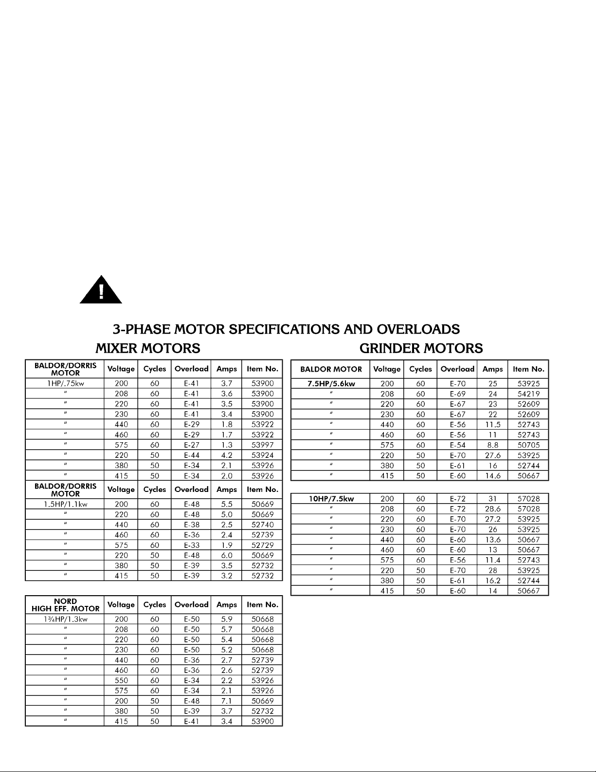
2. All grinders are wired 220 volts unless otherwise specified. Be sure motor specifications (voltage, cycle, phase)
match power supply line. Be sure line voltage is up to specification.
3. Electrical connections to be in accordance with safety codes and National Electrical Code.
4. Rated voltage of the unit shall be identical with full supply voltage.
5. Voltage drop on the supply line shall not exceed 10% of full supply voltage.
6. The feederline conductor size in the raceway from the branch circuit to the unit must be correct to assure
adequate voltage under heavy starting and short overload conditions.
7. The feederline conductor shall only be used for the supply of one unit of the relevant horsepower. For
connections of more than one unit on the same feederline, a local electrician will have to be consulted to
determine the proper conductor size.
8. The size of the electrical wiring required from the power source to the mixer grinder with 7½HP grind motor is a
MINIMUM of No. 10 Wire. With 10HP grind motor MINIMUM of No. 8 WIRE to be used.
9. The BIRO Manufacturing Company is not responsible for permanent wiring, connection or installation.
4
NOTE TO OWNER AND ELECTRICIAN: IF THIS MACHINE IS NOT CORD
AND PLUG CONNECTED TO THE ELECTRICAL SUPPLY SOURCE, THEN IT
SHOULD BE EQUIPPED WITH, OR CONNECTED TO, A LOCKABLE,
MANUALLY-OPERATED DISCONNECT SWITCH (OSHA 1010.147).
Page 9
10. Two sets of green and red pushbuttons are located on the front of the machine that activate the magnetic
contactors that control the mix and grind motors. The magnetic interlock switch is mounted in the pushbutton
box. It lines up with the magnet attached to the product mixer safety cover. When the safety cover is raised the
machine will stop operation.
11. Push the green start button for grind. CHECK THE ROTATION OF THE AUGER DRIVE SHAFT; ROTATION
MUST BE COUNTER-CLOCKWISE as indicated by the rotation decal affixed to the grinding bowl. ROTATION
MUST ONLY BE CHECKED WITH THE GRINDING AUGER REMOVED, otherwise serious irreparable damage
may occur to grinding components.
12. Push the green start button for mix. CHECK ROTATION OF THE MIXING PADDLE; ROTATION MUST BE
COUNTER-CLOCKWISE as indicated by the rotation decal located on the paddle front mounting hub.
Backwards operation will not allow mixing paddle to feed product to the grinding auger.
13. If machine runs clockwise (backwards), it must be rewired to correct rotation, otherwise serious irreparable
damage may occur to grinding components. Both the auger and the mixing paddle must operate in the same
direction.
14. Check operation of optional footswitch if equipped. Plug footswitch cord into fitting at the bottom of the
pushbutton control box. Move toggle selector to foot. The machine will operate with pressure on the footswitch
treadle. Releasing the treadle stops the machine. The footswitch operates the mix and grind together.
15. Insert auger assembly into grinding bowl, place knife (sharp edges out) onto the square end of the auger
assembly. The breaker plate slides over the worm knife drive pin, and is held from rotating by pins in the grinding
bowl. Install the retaining ring.
ONLY HAND TIGHTEN RETAINING RING
For best results, use knife and plate as a set. Do not operate machine for any period of time without product
in the grinding bowl. This will cause heating and dulling of the knife and plate.
16. Check placement of all warning labels and Manual. Machine is now ready for trained operators to process
product.
17. Use meat deflector attached to grinding bowl to eliminate meat splatter.
18. Contact your local Distributor or BIRO directly if you have any questions or problems with the installation or
operation of this machine.
5
Page 10

OPERATION
ROTATING GRINDING AUGER & ROTATING MIXING PADDLE
TO AVOID SERIOUS PERSONAL INJURY
· ONLY Properly Trained Personnel Should Use This Equipment.
· NEVER Place Hands Into Machine Input or Output Openings.
· NEVER Open Machine During Operation.
· DO NOT Wear Gloves While Operating.
· DO NOT Tamper With, Bypass, Alter, or Modify This Equipment in Any Way From Its Original
Condition.
· NEVER Operate Machine With Product Mixer Safety Cover Opened or Removed or Magnetic
Interlock Switch By-Passed.
· ALWAYS Turn Off, Unplug Machine from Power Source and Perform Lockout/Tagout
Procedure to This Machine Before Unjamming, Unclogging, Cleaning or Servicing.
· NEVER Leave Unattended While Operating.
· NEVER Operate Without All Warning Labels Attached and Owner/Operator Manual Available to
the Operator.
A. TO PROCESS PRODUCT
1. Before starting mixer grinder, have a container for receiving ground product at the output end of the grinding
bowl.
2. FIRST GRIND
a. Fill Product Hopper (Maximum 200 Pounds), close Product Mixer Safety Cover.
b. Push both grind and mix green start buttons to feed first grind. It is recommended to use a breaker plate
with
3
8
" diameter or larger holes.
c. Push both grind and mix red stop buttons when all product has been ground out.
3. SECOND GRIND
a. Fill Product Hopper (Maximum 200 Pounds), close Product Mixer Safety Cover.
b. Push the mix green start button only. During this mix operation seasonings may be added through the
sight holes in the Product Mixer Safety Cover.
c. After the desired mix, push the green grind start button to operate grinding auger and grind out product.
d. Push both grind and mix red stop buttons when all product has been ground out.
4. Unplug from power source and perform lockout/tagout procedures.
6
Page 11

CLEANING
ROTATING GRINDING AUGER & ROTATING MIXING PADDLE
TO AVOID SERIOUS PERSONAL INJURY
· ALWAYS Turn Off, Unplug From Power Source and Perform Lockout/Tagout Procedures to
This Machine Before Cleaning or Servicing.
· ONLY Use Recommended Cleaning Equipment, Materials, and Procedures.
· NEVER Spray Water or Other Liquid Substances Directly at Motor, Power Switch or any Other
Electrical Components.
· ALWAYS Thoroughly Clean Equipment at Least Daily.
CLEANING THE BIRO MIXER GRINDER
1. Disconnect mixer grinder from power source and perform lockout/tagout procedures.
2. Remove grinding bowl end ring, breaker plate, knife and grinding auger.
3. Remove mixing paddle. Be sure front most paddle arm is pointing up. Loosen the thumb screw on the mixer
paddle lock arm (Item No. 53853). While supporting the mixing paddle, remove the lock arm. Turn the mixing
paddle counterclockwise, slide forward to disengage from drive shaft and lift from product hopper.
DO NOT POWER SPRAY DIRECTLY AT ELECTRICAL COMPONENTS
4. Machine is now ready to be cleaned using warm soapy water and rinsed with clean water. Machine may be
cleaned by power spray washing, taking care to not spray directly at any electrical controls.
5. The grinding head can be removed for cleaning if desired. This is accomplished by removing the three nuts on
the back flange of the grinding head.
6. After machine has been cleaned and allowed to dry, all exposed metal surfaces should be coated with a good
food grade light oil or grease.
7
CLEANING THE BOWL - RING AND WORM
CARE OF TIN COATED PRODUCTS
(DO’S AND DON’TS)
1. Do not use abrasive cleaning materials, such as Brillo pads or metal scrapers. Tin is a soft metal and should be cleaned
with a soft cloth and dried.
2. Do not use a cleaning agent containing a high percentage of free alkali or acid.
3. Do not use detergent containing a high percentage of tri-sodium phosphate or meta-silicate. Tin is reactive to both.
4. Rinse well and dry thoroughly after washing to remove agents that may be reactive to tin.
5. If sterilizing agent containing chlorine is used, the tinned surface must be thoroughly rinsed. Chlorine is corrosive to tin.
6. Dry thoroughly after rinsing and store in a dry environment.
7. If water is exceptionally hard, drying will be necessary to prevent spotting.
Page 12

MAINTENANCE
ROTATING GRINDING AUGER & ROTATING MIXING PADDLE
TO AVOID SERIOUS PERSONAL INJURY
· ALWAYS Turn Off, Unplug from Power Source and Perform Lockout/Tagout Procedures to
This Machine BEFORE Servicing.
· NEVER Touch This Machine Without Training and Authorization By Your Supervisor
· NEVER Place Hands Into Machine Input or Output Openings.
· NEVER Bypass, Alter or Modify This Equipment in Any Way From Its Original Condition.
· PROMPTLY REPLACE Any Worn or Illegible Warning Labels.
· USE ONLY GENUINE BIRO Parts and Accessories Properly Installed.
A. GRINDING BOWL INSTALLATION
1. Mount the grinding bowl on the three threaded studs on the front of the machine. Tighten in position with
provided nuts.
2. Place the grinding auger in the grinding bowl and fully seat rear drive tang into auger drive shaft.
3. Install knife, breaker plate and end retaining ring.
ONLY HAND TIGHTEN RETAINING RING
4. When the bowl assembly is mounted and tight, there should be approximately
1
8
" gap between the back
inside wall of the grinding trough and the back of the auger. The bowl ring wrench which is provided with
each mixer grinder is used only for REMOVAL of the end retaining ring for cleaning purposes or for changing
knife and breaker plate.
B. MIXING PADDLE INSTALLATION
1. Check that mixer paddle drive pin (Item No. 53516) in the mixer paddle drive shaft (Item No. 53955-N) is
positioned vertically.
2. Holding the mixing paddle by the center shaft and with the front blade up carefully fit drive receiving collar
onto the end of the drive shaft. Insert paddle lock arm assembly (Item No. 53852) into the front of the mixing
tub and onto the front of the mixing paddle.
3. When fully seated, turn the lock arm counterclockwise so the protruding arm is behind the lock set screw
bracket. Tighten the mixer paddle lock set screw (Item No. 53568).
C. LUBRICATION
1. MOTORS: The mix and grind motors have pre-lubricated bearings. These bearings should be re-lubricated
annually with a good grade of bearing grease. Do not over-grease.
2. BEARING HOUSING: The main bearings are housed in an enclosed and sealed journal box. Re-lubricate
semi-annually with a good grade of bearing grease. Do not over-grease.
8
Page 13

OPERATING AND MAINTENANCE INSTRUCTIONS
3. FOR NORD HELICAL – WORM GEAR AND MOTOR REDUCER
ELECTRICAL CONNECTIONS
Check the motor nameplate to verify the phase, hertz and
voltage agrees with the available power supply. Connection
should conform to local codes. A connection diagram for
the motor is located inside the conduit box and on the
motor nameplate. The motor starter has overload
protector.
START-UP
All units are lubricated before shipment. The lubricant level should be
checked with the unit mounted in its correct operating position. Lubricant
should be added or removed to bring it to the correct level.
MAINTENANCE
A. MOTOR
During maintenance, inspect the fan guard and remove any accumulated debris from under or around the
gear reducer. Motor bearings are greased and sealed for life. Motor requires no periodic maintenance.
B. GEAR REDUCER
All units are filled from factory with ISO VG680as. This is a Polyglycol (PG) type synthetic lubricant. Units
should be checked periodically for increase noise, surface temperature, vibration, shaft movement, and
amperage draw. Gear reducer should have the lubricant changed every 20,000 hours or four years,
whichever occurs first. For adverse operating conditions the interval should be shorter. DO NOT MIX
SYNTHETIC & MINERAL BASE OILS. After the unit is drained of the used lubricant, it should be filled
with approximately 1.48 Qts. of a compatible lubricant to the above specification. Once the unit is filled,
the lubricant level should be verified at the Oil Level Plug.
Please note the chart below for oil compatibility:
The listing below offers suggestions on the
manufacturers of recommended lubricants. Use
synthetic oil (Polyglycol-Base) between 14 – 175°
with an ISO Viscosity Class of ISO VG 680.
Aral Degol GS 680 Klober Klubersynth GH 6-680
BP Enersyn SG-XP 680 Mobile Glycgoyle HE 680
Texaco Pinnacle 680 Tribol 800/680
9
Item No. Description
1773-1 Lock Ring ½²
35220 Motor cord SO 14/4´41²
53511 Cord connector 14/4 AL.
53516 Mixer paddle drive pin
53769-35 Mixer drive shaft key
53769-47 Mixer shaft washer retainer
53953 Mixer drive shaft seal
53955-N Mixer drive shaft
57211 Mounting plate
57212 Motor & reducer only – Nord
1¾HP, 208/460V-50/60-3Ph.
57212-2 Motor & reducer only – Nord
1¾HP, 550-575V-50/60-3Ph
57212K Conversion kit & plate – Nord
1¾HP, 200-230V-50/60-3Ph
57212K-1 Conversion kit & plate – Nord
1¾HP, 380-415V-50/60-3Ph
57212K-2 Conversion kit & plate – Nord
1¾HP, 440-460V-50/60-3Ph
57212K-3 Conversion kit & plate – Nord
1¾HP, 550-575V-50/60-3Ph
Item No. Description
57212K-208 Motor & reducer & shaft
replacement w/o plate – Nord
57212K-380 Motor & reducer & shaft
replacement w/o plate – Nord
57212K-440 Motor & reducer & shaft
replacement w/o plate – Nord
57212K-575 Motor & reducer & shaft
replacment w/o plate – Nord
C776 Terminal ring #10
HHS125S Hex head screw, ½-13´1SS
Item No. Description
HHS127S Hex head screw, ½-13
´
1½SS
HHSM059S Hex head screw,
M8´1.25´20mm
HN42S Hex nut, ½-13 SS
LW15S Lock washer,
5
16
SS
LW30S Lock washer, ½ SS
SSS10Z Set screw, ¼-20´¼SS
NORD GEAR CORP.
800 Nord Drive
P.O. Box 376
Waunakee, WI 53597-0367
Page 14

4. FOR DORRIS MIXER TRANSMISSION
DORRIS MIXER TRANSMISSION: Oil in the mixer
transmission should be changed after the first four (4)
weeks of operation. This is to remove the "run-in" oil
and also any small metal shavings that may have been
generated during the initial mating of the gears. After
the first oil change, subsequent changes should be
performed every six (6) months. After draining the oil,
refill the unit to the "level" plug (1 qt.) at the center of
the transmission with a petroleum based rust and
oxidation (R&O) inhibited gear oil. Viscosity Range for
15-75 degrees F (-9 – 24 degrees C) is AGMA Lube No.
3 or ISO Grade 100.
TO CHANGE OIL:
a. Unplug mixer/grinder from power source and
perform lockout/tagout procedures.
b. Remove rear drive cover.
c. Remove breather plug from top of transmission and
oil level plug from side of transmission
d. With a container in place to catch old oil, remove the
magnetic drain plug from the bottom of the
transmission.
e. When all oil has drained, clean the drain plug and
replace into the transmission.
f. Refill transmission with approx. one (1) quart of the
recommended gear oils or equivalent. Or until oil
appears at bottom of oil level sight hole.
g. Replace breather and oil level plugs.
h. Carefully turn mixer transmission pulley by hand to
lubricate internal gears.
i. Reinstall rear drive cover.
D. MIXER DRIVE BELT TENSION
1. Unplug mixer/grinder from power source and perform lockout/tagout procedures.
2. Remove rear drive cover.
3. Loosen the four bolts holding the 1HP motor to its mounting plate.
4. Slide 1HP motor away from mixer transmission.
5. When approximately
1
2
" total belt flex has been attained, retighten motor bolts.
6. Reinstall rear drive cover.
E. MAIN DRIVE CHAIN AND SPROCKET LUBRICATION:
The main drive chain has been pre-lubricated at the factory to protect it against dirt and moisture. Chain life
will vary appreciably depending upon its lubrication. The better the lubrication, the longer the chain life.
Lubrication effectiveness will vary with the amount of lubricant and frequency of application. Ideally, a
lubricant film should always be present between the working parts. Manually lubricate the chain as often as
is needed (possibly once a week). NEVER exceed three months without lubricating.
Lubricating just the outside of the chain does little good. Apply lubrication on the inside of the chain span so
that it will work through the moving parts and joints by centrifugal force as the chain rotates and reach the
area where one surface “scrubs” another.
10
Page 15

MAIN DRIVE CHAIN AND SPROCKETS LUBRICATION (continued):
Recommended types of chain lubricant are those with Molybdenum Disulphide or Graphite added. Also
bonded lubricants such as Dow Corning Molykote 321R or equivalent are excellent for open chains. The
lubricant should be of a viscosity whereby it will “flow” somewhat and penetrate the internal working surfaces.
Thick stiff greases are of little value because they cannot work into moving parts of the chain.
a. Unplug mixer/grinder from power source and perform lockout/tagout procedures.
b. Remove rear drive cover.
c. Spray or brush lubricant on inside of chain, slowly and carefully turning large sprocket by hand.
d. Reinstall rear drive cover.
F. MAIN DRIVE CHAIN TENSION (See Diagram Below)
1. Unplug mixer/grinder from power source and perform lockout/tagout procedures.
2. Remove rear drive cover.
3. Remove right and left side skirts.
4. Loosen the four bolts that hold the motor to the frame of the machine.
5. Loosen the lock nuts on the motor adjusting stud.
6. To Loosen Chain Tension. Turn motor adjusting studs counterclockwise. Grasp motor and pull toward
adjusting stud. Be sure to turn both adjusting studs the same amount and evenly. Total chain flex should be
1
8
"to
3
8
". Be sure to keep motor shaft parallel with auger drive shaft.
To Tighten Chain Tension. Turn motor adjusting studs clockwise. Be sure to turn both adjusting studs the
same amount and evenly. Total chain flex should be
1
8
"to
3
8
". Do not overtighten chain as this will put
excessive and damaging pressure on the motor bearings. Be sure to keep motor shaft parallel with auger
drive shaft.
7. Retighten motor mounting bolts.
8. Retighten motor adjusting stud lock nuts.
9. Reinstall the right and left side skirts.
10. Reinstall the rear drive cover.
G. CHAIN REPLACEMENT
1. Part No. H384-CL Service Replacement Chain is provided with a
"Connecting Link" (Part No. H384-LINK) so that is can be separated to
facilitate installation over the sprockets
Upon assembly, be sure the connecting link is installed so the spring
clip is orientated with its opening facing "opposite" the direction of the
chain travel (See Diagram). â
11
AFTER INSTALLATION
THE CHAIN SHOULD BE
TENSIONED TO
APPROXIMATELY
1
8
to
3
8
FLEX
Page 16

12
Page 17

— NOTES —
13
Page 18

AFMG-48 SIDE VIEW PARTS DIAGRAM
14
Page 19

Fig. Item No. Description
1 57154 Product mixer safety cover, tri directional,
#63592 on
1A 53547 Lid with chute opening
1B 53543 Conveyor chute
2 56072 Safety cover latch
3 56073 Safety cover latch mounting bracket, L.H.
4 56074 Safety cover latch mounting bracket, R.H.
5 AN20S Acorn nut,
3
8
-16 (2 req.)
6 RHS24S Round head screw,
1
4
-20
´
1
2
(2 req.)
HNNL15S Hex nut, nylok,
1
4
-20 (2 req.)
7 RHS31S Round head screw,
1
4
-20´1
HNNL15S Hex nut, nylok,
1
4
-20
8A 53456 Mixer paddle assembly, 1st grind, optional
8B 53918 Mixer paddle assembly, 2nd grind,
standard
9 53953 Mixer drive shaft seal
10 53516 Mixer paddle drive pin
11 SSS10Z Drive pin set screw
12 53594 Bearing for 53520 assembly
13 53517-1 Thrust bearing
14 53852 Lock arm assembly w/brgs.
15 53568 Mixer paddle lock set screw
16 57047 Wireway cover, #63401 on
17 1116 Acorn nut, 10-32 (3 req.)
18 SSS45S Meatguard mounting stud
19 WN20S Wing nut
20 52392 Meat guard splash shield
21 HK48 Knife drive pin
22 HP48 Bowl plate pin (3 req.)
23 HR42/48 Bowl ring
24 52106-CTN Bowl w/plate pins
25 54278-CTN Auger assembly
25B 54278B Square drive auger adapter
25C 54278C Auger shear pin
25D FHS33S Shear pin flat head screw,
1
4
-20´½
26 53413 Bowl mounting stud – short (1 req.)
HNF42S Hex flange nut,
1
2
-13, (2 req.)
26A 53413-2 Bowl mounting stud – long (2 req.)
26B HNF42S Flange hex nut ½-13 bowl mounting nut
(3 req.)
27 57159K Auger drive shaft seal kit
27A 57160 Seal retainer, SS
27B 57159 Auger drive shaft seal, double lip
27C FHS26S Flat head screw 10-32
´
3
4
,SS
28 53475-200 Motor, 7½HP, 200/400-60-3
53475 Motor, 7
1
2
HP, 208/460-60-3
53475-50 Motor, 7½HP, 208/380-50-3
53941 Motor, 7
1
2
HP, 575-60-3
53475-1 Baldor 7½HP, bearing both ends –
206KDD
53475-2 Doerr 7½HP, bearing, opp. shaft –
206KDD
53475-3 Doerr 7½HP, bearing, shaft end –
207KDD
57025-200 Motor, 10HP, 200/400-60-3
57025 Motor, 10HP, 208/460-50/60-3
57025-5 Motor, 10HP, 575-60-3
57092 Motor, 10HP, 220/380-50-3
29 53886 Journal box assembly
30 H384-CL Roller chain
31 54310 Adjusting stud
32 55092 Rear drive cover w/handles
55092-COSK Rear drive cover COS kit
55092-COS Rear drive cover w/handles & magnet
14688 4-point knob, AL
14688-COS Locking knob, AL
57219 Screw – COS rear drive cover
FW05S Flat washer ¼, SS
FW16S Flat washer
5
16
,SS
HHS025S Hex head screw ¼-20
´
½, SS
HHS049S Hex head screw
5
16
-18´½, SS
HHS050S Hex head screw
5
16
-18
´
5
8
,SS
Fig. Item No. Description
HHS055S Hex head screw
5
16
-18´¾, SS
HN07S Hex nut 10-24, SS
HN15S Hex nut ¼-20, SS
HN20S Hex nut
5
16
-18, SS
LW10S Lock washer ¼, SS
LWE10P Lock washer #10 ext tooth, SS
33 53478 Starter w/110V coil, Furnas size 1,
14DP32AF81, 7
1
2
HP
55046 Starter w/24V coil, Furnas size 1,
14DP32AJ71, 7½HP
75DF14 Contact kit, Furnas 1 pole only (size 1)
7½HP
57027 Starter w/110V coil, Furnas size 1
3
4
,
14EP32AF81, 10HP
57027CE Starter w/24V coil, Furnas size 1¾,
14EP32AJ71, 10HP
75EF14 Contact kit, Furnas 1 pole only (size 1¾)
10HP
33A 34478 Holding coil – 120V/240V
55047 Holding coil – 24V
34 53851 Fuse, FNM-1 AMP, 250V timedelay
35 53914 Transformer, 230/460 to 115V
53731 Transformer, 575 to 115V
PC141-1 Transformer replacement,
200/208/220/240/277/380 to 24V
36 See electrical diagram, page 4
37 53477 Starter w/110V coil, Furnas size 00,
14BP32AF81, 1¾HP
55045 Starter w/24V coil, Furnas size 00,
14BG32AJ71, 1HP
75BF14 Contact kit, Furnas 1 pole only (size 00)
1HP
37A 34478 Holding coil – 120V/240V
55047 Holding coil – 24V
38 53633 Starter box cover
39 53860 Starter box
40 52181-1 Magnetic switch bracket for magnet
41 52181-1 Magnet w/mounting brkt. (110 volt)
PC166 Magnetic safety switch (24 volt) old style
units only (not CE)
42 42MC-Y73 Green start button
43 H442-1 Magni switch, 3 amp
53872 Safety switch mounting bracket
44 42MC-Y74 Red stop button
45 50655-1 Switch guard
H462-1 Switch guard ferrule
HN20S Hex nut
5
16
-18 SS
LW15S Lock washer
5
16
SS
46 54320K Toggle switch,hand/foot, w/boot
47 54321 Toggle switch waterproof half boot
48 53869CEK Legend plate, w/int’l. symbols, int'l kit
49 53870 Legend plate gasket
50 52655 Female receptacle, 5 pole, for footswitch
51 52662 Protective cap assembly
52 53872 Safety switch bracket
53 35376 End anchor
54 35241 Mounting channel
55 35375 End barrier
56 35374 Terminal block
57 53783 Decal, rotation
58 57156 Front splash shield
HHS025S Hex head screw ¼-20
´
½, SS
HN15S Hex nut ¼-20, SS
LW10S Lock washer ¼, SS
NOT SHOWN
57073 Power cord, 10’, 8-4
54268 Power cord, 10’, 10-4
2563 Legend plate hex screw
10-32
´
1
2
,SS
53965 Optional leg ext. kit with brace
BIRO MODEL AFMG-48-II MIXER GRINDER PARTS LIST
15
Page 20

16
Fig. Item No. Description
1 56221 Safety cover torsion spring, R.H.,
#63401 on
56222 Safety cover torsion spring, LH.,
#63401 on
2 57050 Safety cover hinge rod, #63401 on
2A 57153 Tri directional hinge rod, for front
opening, #63440 on
2B 56045 Hinge rod spacer (2 req'd)
2C AN20S Acorn nut
3
8
-16, SS (2 req'd)
3 53755 Motor, 1HP, 208/460-60-3
53755-50 Motor, 1½HP, 220/380/50-3
53942 Motor, 1HP, 575-60-3
57210 Motor, 1½HP, 200-60-3
4 53771 Transmission & motor mounting
bracket, #62001 on
5 53769 Transmission (Dorris), #62001 on
6 53955 Mixer drive shaft
7 53773 Transmission mounting angle,
#62001 on
8 54303 Outer disc, double rod, #62001 on
9 14688 Lock knob, (2 req.)
10 57133 Side entrance seal, double rod, 35°
inlet, #63592 on
10A 54302 Side entrance seal, double rod, 90°
inlet, #62001 to #63591
11 53891 Auger drive shaft key
12 53894 Auger drive shaft lockwasher
13 53715 Ring wrench hanger
HN15S13A Hex nut ¼-20, SS
14 52357 Ring wrench (order H340)
15 55093 Right side skirt, 35° inlet, #63592 on
15A 55094 Right side skirt – no hole
15B 55095 Right side skirt, 90° inlet, #52001 to
#52344
16 53580 Sprocket, 22 tooth (order H382-1)
H382 Sprocket – 19 tooth (replacement
only)
17 PC175-1 Swivel caster w/total lock (4 req.) –
new style
53952 Swivel caster w/lock (4 req.) – old
style
18 53944-1 Standard leg, 9
1
2
" adjusting – new
caster pad style
53944-5K Foot leg pad bumper kit (4 ea.)
53944 Standard leg, 9
1
2
" adjusting – old
caster pad style
19 55096 Left side skirt – 35° inlet
19A 55097 Left side skirt – no hole
19B 55098 Left side skirt, 90° inlet
20 53727 Main sprocket #62001 on
21 53895 Auger drive shaft locknut #62001 on
22 16251-90X78AL
Pulley, (driven) 9
´
7
8
I.D.
23 15063 V-belt 5L350
24 53469 Pulley, (driving), 3.15
´
7
8
I.D.
25 57201K Motor bracket support bar kit
26 C617 Motor shaft key ¼´¼´2²
Page 21

OPTIONAL STAINLESS STEEL BOWLS, AUGERS & RINGS
17
Fig. Item No. Description
1 53446 Lid assembly to #63400
2 HN30S Hex nut,
3
8
-16, SS (2 ea.)
3 51563 Lid hinge pin to #63400 (2 ea.)
4 53530 Lid lock arm to #63400
5 53533 Lid lock spacers to #63400 (2 ea.)
6 AN15S Acorn nut,
1
4
-20, SS (2 ea.)
7 HHS035S Hex head screw,
1
4
-20
´
5
8
,SS
(2 ea.)
Fig. Item No. Description
8 FW05S Flat washer,
1
4
, SS (2 ea.)
9 56072 Safety cover latch
10 56073 Latch mounting bracket, LH
11 56074 Latch mounting bracket, RH
12 RHS24S Round head screw,
1
4
-20
´
1
2
,SS
(2 ea.)
13 HNNL15S Hex nut,
1
4
-20 nylok (3 ea.)
14 RHS31S Round head screw,
1
4
-20´1, SS (1
ea.)
Fig. Item No. Description
55081 Lid lock retrofit kit
S/N 63401 to 63696
1 55059 Lid lock
2 55061 Lever arm assembly
3 2503 Nylon washer, .125 thick (2 ea.)
4 2504 Nylon washer, .060 thick (4 ea.)
5 AN17S Acorn nut,
5
16
-18, SS (2 ea.)
6 FHS33S Flat head screw,
1
4
-20
´
1
2
,SS
(2 ea.)
7 HN15S Hex nut,
1
4
-20, SS (2 ea.)
114mm UNGER
Item No. Description
FHS33S Shear pin fastener ¼-20´½SS
HHS012S Hex head screw, 10-32
´
1
2
SS
HK114 Knife drive pin, 114mm Unger
HR42/48S-114 End ring, SS, 114mm Unger
LW05S Lock washer, #10, SS
52106S-114 Bowl, SS, 114mm Unger
54278-CTNS-114
Auger assembly, SS, 114mm
Unger
54278C Auger shear pin
56049SK-114 Key, 114mm Unger
ENTERPRISE
HR42/48S End ring, SS
52106S Bowl, SS
54278-CTNS Auger assembly, SS
Page 22

DORRIS MIXER TRANSMISSION PARTS LIST
18
H369 Hex head screw
5
16
-18´¾
LW30S Lockwasher, SS
1
2
"
0850 Setscrew
1
4
-20
´
1
4
" long
1084 Hex head cap screw
1
2
-13´1
1
4
long
1103 Set screw
1
4
-20
´
3
8
" long
SSS30 Set screw
3
8
-24
´
3
4
" long
53516 Mixer drive pin
53769 Mixer paddle transmission
53769-01 Transmission housing
53769-03 Cover plate
53769-05 Low speed open cap
53769-06 High speed closed cap
53769-07 High speed open cap
53769-08 Low speed shaft
53769-09 Intermediate pinion gear
53769-10 High speed pinion gear
53769-11 Intermediate gear
53769-12 Low speed gear
53769-20 Intermediate closed cap
53769-31 High speed shaft key
53769-32 Intermediate gear key
53769-33 Low speed gear key
53769-35 Low speed shaft key
53769-36 Low speed Timken cup
53769-37 Low speed Timken cone
53769-38 High speed Timken cup (closed end)
53769-39 High speed Timken cone (closed end)
53769-40 High speed Timken cup (open end)
53769-41 High speed Timken cone (open end)
53769-42 Intermediate Timken cup
53769-43 Intermediate Timken cone
53769-44 Intermediate spacer ring
53769-45 Low speed spacer ring
53769-46 High speed spacer ring
53769-47 Puller shaft seal
53769-57 Intermediate shims
53769-58 High speed shims
53769-59 Low speed shims
53769-60 Cover plate gasket
53769-61 High speed oil seal
53769-62 Low speed oil seal
53769-63 Hex screw (intermediate cap)
53769-64 Hex screw (high speed cap)
53769-69 Hex screw (low speed cap)
53769-71 Hex screw (cover)
53769-74 Breather plug
53769-75 Magnetic drain plug
53769-96 Grease fitting
53953 Mixer drive shaft seal
53955 Mixer drive shaft
Page 23

NO. 53886 JOURNAL BOX ASSEMBLY
19
FOOTSWITCH PARTS LIST
224-2 Cord connector, wt, straight,
3
4
"
52654 Male plug w/6’ cord, 5 wire
52655 Female receptacle, 5 pole
52661 Male plug w/12’ cord, 5 wire
52668 Footswitch w/12’ cord and plug
53693 Footswitch
53693-A Cover guard
53693-C Cover gasket
53693-D Cover screw – short
53693-E Cover screw – long
53693-F Ground screw
53693-G Treadle spring
53693-H Internal assembly complete
53693-I Actuator
53693-M Micro switch BA-2R62-A4
53693-O Washer
53693-T Treadle w/actuator & return spring
53693-U Auxiliary treadle return spring
53693-W Treadle
53693-X One actuator & actuator spring assembly
54213 Foot switch w/6’ cord & plug
Item No. Description
53609 Journal box, #62001 on
53724 Auger drive shaft, #62001 on
53785 Journal box seal (2 ea.)
53886 Journal box assembly complete
53888, 53940 Front bearing cup/cone assembly
Order H310A
53889, 53939 Rear bearing cup/cone assembly
Order H311A
53993 Vented grease fitting
53979-1 Cord 8’ w/o foot switch
54213 Foot switch w/6’ cord & plug
Page 24

20
TANDEM OPERATION
PARTS LIST
272-7-1
5
16
-18 plastic knob – 3 pt.
53489 Dscg. Horn 24/42/46/48 to 24/48/52
inlet less seal
57044 Connec. brkt. AFMG52 to AFMG48
57044 Connec. brkt. AFMG52 to AFMG52
53552-1A Connecting brkt. assem. man/auto
53604 Dscg. horn 52 to 24/48/52 inlet
53667 Dscg. horn 56 to 24/48/52 inlet
53671 Seal only 24/42/46/48 to 24/48/52
inlet
53673 Disc. horn 48-52 w/seal
53933 Seal only 52/56 to 24/48/52 inlet
Page 25

TANDEM OPERATION ILLUSTRATION FOR 90° INLET
FROM S/N 62001 TO S/N 63591
21
Page 26

22
Page 27

CONNECTION INSTRUCTIONS
TANDEM OPERATIONS
AFMG-48 or ARFMG-52 INTO AFMG-48 or AFMG-52
Heavy Horsepower Grinder INTO AFMG-48 or AFMG-52
23
Remove Side Entrance Seal, Item No. 57133; Outer Disc, Item No. 54303 and
Lock Knobs, Item No. 14688 from the inlet tube of the Second Grind Machine.
Clean out the tube if necessary.
Install the Inlet Tube Seal Item No. 53671 or 57145
into the inlet tube of the Second Grind Machine until
fully seated.
Remove the Ring from the First Grind Machine, Item No. HR42/48 or HR52. Insert the Discharge Horn, Item No. 57144-7 or 57143-7 into the ring. (DO NOT
reinstall the ring on the First Grind Machine at this time.) Slide the Clamp Assembly, Item No. 57144-11 or 57143-11 onto the Discharge Horn.
Insert the Discharge Horn with Ring and Clamp Assembly
into the Seal, pushing it fully against the inlet tube internal
fins. Attach the lock latches to the tabs on the side of the
inlet tube and lock down. Tighten the lock knob on the
Clamp Assembly.
Move the Discharge Horn of the Second Grind Machine up to the Bowl of the First
Grind Machine. With the Auger, Knife and Grinding Plate installed in the First
Grind Machine, thread the Ring onto the First Grind Machine Bowl. RING
SHOULD BE HAND TIGHTENED ONLY: USE NO TOOLS.
Page 28

TANDEM OPERATION ILLUSTRATION FOR 35° INLET
S/N 63592 ON
24
Page 29

Page 30

OPERATOR’S SIGNATURE PAGE
MY SIGNATURE ATTESTS THAT I HAVE COMPLETELY READ AND UNDERSTAND THIS
MANUAL. I REALIZE THAT THIS MACHINE, IF OPERATED CARELESSLY, CAN CAUSE SERIOUS INJURY TO MYSELF AND OTHERS.
NAME (PRINT) SIGNATURE
SUPERVISOR’S
INITIALS
DATE
26
Page 31

— NOTES —
27
Page 32

LIMITED WARRANTY
WARRANTY: The Biro Manufacturing Company warrants that the BIRO AFMG-48-II Mixer
Grinder/Chopper will be free from defects in material and workmanship under normal use and with
recommended service. BIRO will replace defective parts, which are covered by this limited warranty, provided that the defective parts are authorized for return, shipping charges prepaid, to a
designated factory for inspection and/or testing.
DURATION OF WARRANTY: The warranty period for all parts covered by this limited warranty is
one (1) year from date of inspection/demonstration as advised on the returned Warranty registration card, or eighteen (18) months from original factory shipping date, whichever date occurs first,
except as noted below.
PARTS NOT COVERED BY WARRANTY: The following are not covered by this limited warranty:
wearable parts in the grinding system such as bowl, ring, worm, drive shaft, and knife drive pin.
This limited warranty does not apply to machines sold as used, rebuilt, modified, or altered from
the original construction in which the machine was shipped from the factory. Water contaminated
electrical systems are not covered under this limited warranty. BIRO is not responsible for electri cal connection of equipment, adjustments to the switch controls or any other electrical requirements, which must be performed only by a certified electrician. BIRO is not responsible for service
charges or labor required to replace any part covered by this limited warranty or for any damages
resulting from misuse, abuse, lack of proper or recommended service.
EXCLUSION OF WARRANTIES AND LIMITATION OF REMEDIES: BIRO gives no warranties
other than those expressly stated in this limited warranty. THE IMPLIED WARRANTY OF MERCHANTABILITY, THE IMPLIED WARRANTY OF FITNESS FOR PROCESSING OF FOOD PRODUCTS, AND ALL OTHER IMPLIED WARRANTIES ARE SPECIFICALLY EXCLUDED. BIRO IS NOT
LIABLE FOR CONSEQUENTIAL OR INCIDENTAL DAMAGES, EXPENSES, OR LOSSES. THE
REMEDIES PROVIDED IN THIS BIRO LIMITED WARRANTY ARE PURCHASER’S SOLE AND EXCLUSIVE REMEDIES AGAINST BIRO.
REGISTRATION CARDS: You must sign, date and complete warranty registration card supplied
with each machine. The warranty card must be returned to The Biro Manufacturing Company for
proper registration. If no warranty card is returned to BIRO, the warranty period will begin from
the date the machine was originally shipped from the factory.
HOW TO GET SERVICE:
1. Contact the entity from whom you purchased the machine; or
2. Consult the yellow pages of the phone directory for the nearest authorized dealer; or
3. Contact BIRO Mfg. Company for the authorized service entity (250 plus worldwide) in your area.
THE BIRO MANUFACTURING COMPANY
1114 Main Street
Marblehead, Ohio
Ph. 419-798-4451
Fax 419-798-9106
E-mail: service@biro saw.com
Web: http://www.birosaw.com
28
ITEM NO: 53913
PTCT AFMG 48-138-9-05-12 COMM
ITEM NO: 53913
PTCT AFMG 48-138-4-08-13 PPD
 Loading...