

Page 1

+
IMPORTANT NOTICE
+
This Manual contains important
safety instructions which must
be strictly followed when using
this equipment.
Page 2

TABLE OF CONTENTS
Page
NOTICETOOWNERANDOPERATORS.......................................... 1
SAFETYTIPS............................................................... 2
INSTALLATION ............................................................. 3
WARNINGLABELS............................................................5
OPERATION................................................................ 6
TOPROCESSPRODUCT.................................................... 6
CLEANING................................................................. 8
MAINTENANCE ............................................................. 9
GENERAL................................................................ 9
LUBRICATION ............................................................10
CHANGINGTHESAWBLADE ................................................10
WARNINGLABELLOCATIONSONMACHINE......................................11
PARTSDIAGRAMS...........................................................12
OPERATOR'SNOTES.........................................................17
WIRINGDIAGRAM ...........................................................23
OPTIONAL DOUBLE ROLLING TABLES PARTS LIST & DIAGRAMS . . . . . . . . . . . . . . . . . . . . . 24
OPTIONAL FIXED FRONT TABLE PARTS LIST & DIAGRAMS . . . . . . . . . . . . . . . . . . . . . . . . . . 25
PARTSLIST/ORDERING.......................................................26
PARTSASSEMBLIESLIST/ORDERING ...........................................27
WEARABLESAWPARTS ......................................................28
OPERATOR'SSIGNATUREPAGE................................................29
LIMITEDWARRANTY.........................................................30
Page 3

NOTICE TO OWNERS AND OPERATORS
BIRO’s products are designed to process food products safely and efficiently. Unless the operator is properly trained and supervised, however, there is the possibility of a serious injury. It is the
responsibility of the owner to assure that this machine is used properly and safely, strictly following
the instructions contained in this Manual and any requirements of local law.
No one should use or service this machine without proper training and supervision. All operators should be thoroughly familiar with the procedures contained in this Manual. Even so BIRO
cannot anticipate every circumstance or environment in which its products will be used. You, the
owner and operator, must remain alert to the hazards posed by the function of this equipment –
particularly the SHARP MOVING BAND TYPE SAW BLADE. No one under eighteen (18) years of
age should operate this equipment. If you are uncertain about a particular task, ask your
supervisor.
This Manual contains a number of safe practices in the SAFETY TIP section. Additional warnings are placed throughout the Manual. Warnings related to your personal safety are indicated by:
Warnings related to possible damage are indicated by:
BIRO also has provided a wall chart to be posted near the equipment. If any warning label, wall
chart, or Manual becomes misplaced, damaged, or illegible, please contact your nearest Distributor or BIRO directly for a replacement.
Remember, however, this Manual or the warning labels do not replace the need to be alert and
to use your common sense when using this equipment.
This Manual applies to all Model 55 Power Saws.
1
OR
– NOTE –
“A copy of this manual is included with each Model 55 Saw.”
“The descriptions and illustrations contained in this manual are not binding.
The manufacturer reserves the right to introduce any modification without
replacing the manual.”
Page 4

SAFETY TIPS
SHARP MOVING BAND TYPE SAW BLADE
TO AVOID SERIOUS PERSONAL INJURY
NEVER Touch This Machine Without Training and Authorization By Your Supervisor.
ALWAYS Read Operating and Service Manual BEFORE Operating, Servicing or Cleaning.
ALWAYS Keep Hands Clear of Band Type Saw Blade and Other Moving Parts.
ONLY Use a Qualified Electrician to Install According to Local Building Codes: Machine MUST
Be Properly Grounded.
ONLY Install on a Level, Non-Skid Surface in a Clean, Well-Lighted Work Area Away From
Children and Visitors.
DO NOT Attempt to Operate This Machine Until it has Been Inspected and Demonstrated by the
Seller – Recognized BIRO Representative.
DO NOT Alter or Modify This Machine in any Way From its Original Form. This Machine in its
Original Form Meets the Intent of O.S.H.A. Applicable Standards.
NEVER Operate With Saw Guide Bar with Saw Guard in the Raised Position or the Saw Guard
Removed from the Saw Guide Bar.
ALWAYS Adjust Saw Guide Bar with Saw Guard to Within
1
2
" of Product to be Cut.
ALWAYS Use Safety End Cut Pusher Plate for Smaller Products or The Last Cuts of Product.
DO NOT Use This Machine for Non-Food Products.
DO NOT Use This Machine to Cut Pigs Feet.
DO NOT Wear Gloves While Operating.
ALWAYS Turn Off, Unplug From Power Source and Perform Lockout/Tagout Procedure to This
Machine BEFORE Removing Shrouds, Removable Guards, Covers, Doors, Fences or Panels
for Cleaning, Servicing or Any Other Reason.
NEVER Leave Machine Unattended While Operating.
PROMPTLY REPLACE Any Worn or Illegible Warning Labels.
USE ONLY Genuine BIRO Parts and Accessories Properly Installed.
2
Page 5

INSTALLATION
TO AVOID SERIOUS PERSONAL INJURY,
PROPERLY INSTALL EQUIPMENT IN ADEQUATE WORK AREA
ALWAYS Read Operating and Service Manual BEFORE Operating, Servicing or Cleaning.
ALWAYS Use Qualified Technician and Electrician for Installation.
ONLY Install on a Level, Non-Skid Surface in a Clean, Well-Lighted Work Area Away From
Children and Visitors.
DO NOT Attempt to Operate This Machine Until it has Been Inspected and Demonstrated by the
Seller – Recognized BIRO Representative.
DO NOT Alter or Modify This Machine in any Way From its Original Form. This Machine in its
Original Form Meets the Intent of O.S.H.A. Applicable Standards.
NEVER Operate With Saw Guide Bar with Saw Guard in the Raised Position or the Saw Guard
Removed from the Saw Guide Bar.
ALWAYS Turn Off, Unplug From Power Source and Perform Lockout/Tagout Procedure to This
Machine BEFORE Removing Shrouds, Removable Guards, Covers, Doors, Fences or Panels
for Cleaning, Servicing or Any Other Reason.
NEVER Operate Without all Warning Labels Attached and Wall Chart Posted.
USE ONLY Genuine BIRO Parts and Accessories Properly Installed.
1. Read this Manual thoroughly before installation and operation. Do not proceed with installation and operation if
you have any questions or do not understand anything in this Manual. Contact your local Distributor, or BIRO
first.
2. Install machine on a level, solid, non-skid surface in a well-lighted work area away from children and visitors.
3. After installing machine in operational area, it is imperative that the four adjustable legs be adjusted to level the
machine to eliminate rocking. Remove all wood supports.
4. Machine MUST be properly grounded. Use qualified electrician to install according to building codes.
3
ALWAYS LEVEL MACHINE BEFORE USING
NOTE TO OWNER AND ELECTRICIAN: IF THIS MACHINE IS NOT CORD
AND PLUG CONNECTED TO THE ELECTRICAL POWER SUPPLY, THEN IT
SHOULD BE EQUIPPED WITH, OR CONNECTED TO, A LOCKABLE,
MANUALLY OPERATED DISCONNECT SWITCH (OSHA 1010.47).
Page 6
WIRING MOTOR
(A) All power saws are wired at the factory for 220 volts or 440 volts as specified on original order. Be sure motor
specificaitons (voltage, cycle, phase) match power supply line. Be sure line voltage is up to specification.
(B) Connect leads to machine in a manner that will be approved by local electrical inspectors.
(C) We recommend not less than No. 12 wire. If leads are too light, machine may not have sufficient cutting
power and/or speed.
(D) The V-belt is packed loose in machine to prevent deformation, and must be installed on pulleys at time of
installation.
(E) Motors are dual voltage and can be changed according to wiring diagram on motor nameplate. Be sure the
correct AEG contactor and overload is installed to match the selected volts and amps.
(F) FAILURE TO USE THE PROPER CONTACTOR AND OVERLOAD FOR MOTOR VOLTAGE WILL CAUSE
IRREPARABLE DAMAGE TO THE CONTACTOR.
(G) The BIRO Manufacturing Company is not responsible for permanent wiring, connection or installation.
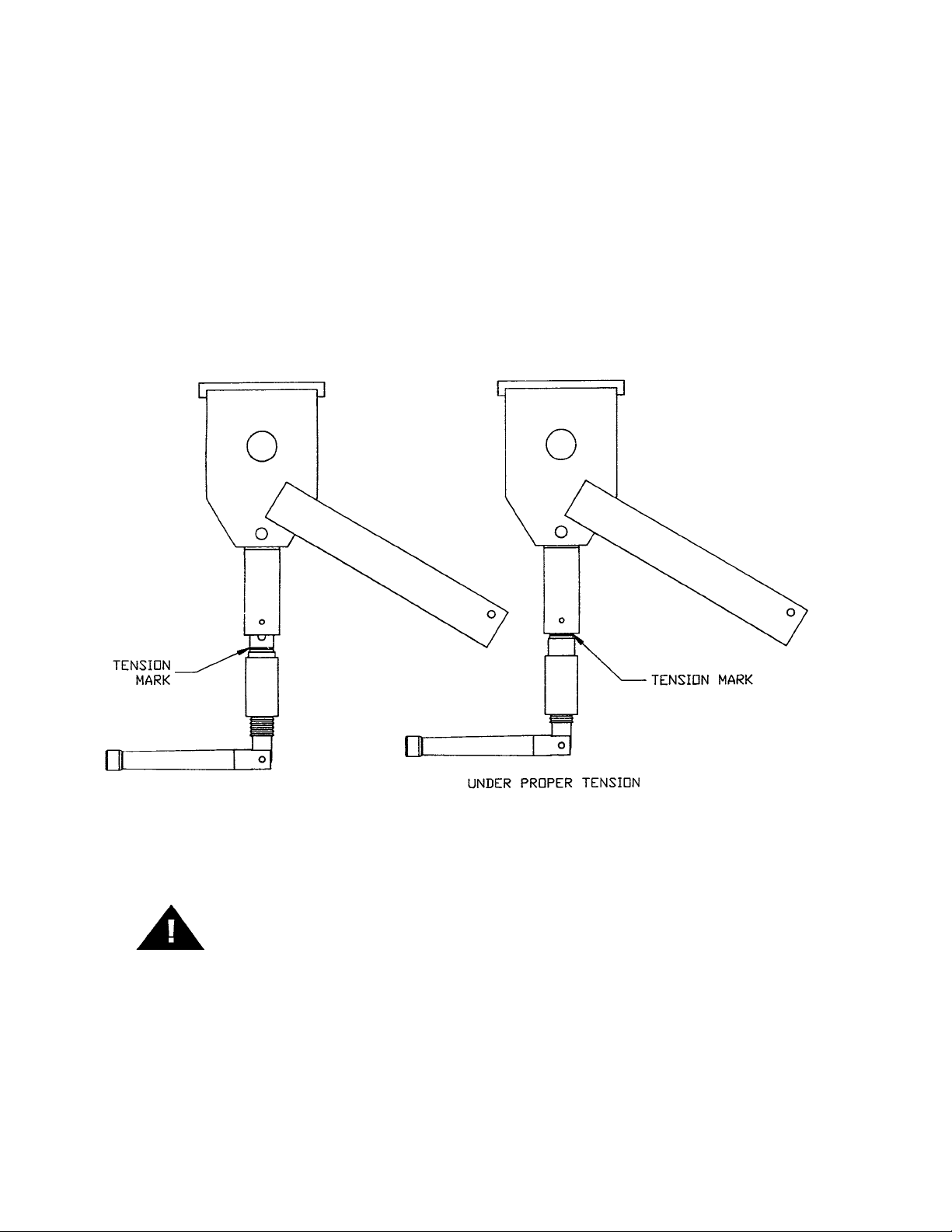
5. Be sure saw blade is properly installed on the saw wheels and set at proper tension. Turn the blade tensioning
handle clockwise until the tension mark is even with the bottom of the upper wheel hinge plate as shown.
6. Make sure the saw guide bar is in its lowest position. Close head and base doors and latch.
7. Push the start button and check for proper phasing of the motor. Blade should be traveling down through the
saw guide.
8. Watch for proper tracking of the saw blade. Back of blade should be centered in the hole in saw guide in
stationary bar (Item No. 119A). Push the stop button to stop machine.
9. Check placement of all warning labels, wall chart and Manual. Machine is ready for trained operators to process
product.
10. Contact your local Distributor or BIRO directly if you have any questions or problems with installation or
operation of this machine.
4
KEEP HANDS CLEAR OF SHARP MOVING BAND TYPE SAW
BLADE
Page 7
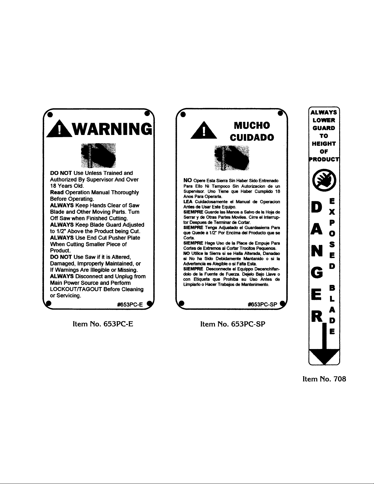
WARNING LABELS
FOR BIRO POWER SAWS
SEE PAGE 11 FOR LOCATIONS ON MACHINE
5
Page 8
OPERATION
SHARP MOVING BAND TYPE SAW BLADE
TO AVOID SERIOUS PERSONAL INJURY
NEVER Touch This Machine Without Training and Authorization By Your Supervisor.
ALWAYS Read Operating and Service Manual BEFORE Operating, Servicing or Cleaning.
ALWAYS Keep Hands Clear of Band Type Saw Blade and Other Moving Parts.
DO NOT Tamper With, Bypass, Alter, or Modify this Equipment in Any Way or Form.
DO NOT Alter or Modify This Machine in any Way From its Original Form. This Machine in its
Original Form Meets the Intent of O.S.H.A. Applicable Standards.
NEVER Operate With Saw Guide Bar with Saw Guard in the Raised Position or the Saw Guard
Removed from the Saw Guide Bar.
ALWAYS Adjust Saw Guide Bar with Saw Guard to Within
1
2
" of Product to be Cut.
ALWAYS Use Safety End Cut Pusher Plate for Smaller Products or The Last Cuts of Product.
DO NOT Use This Machine for Non-Food Products.
DO NOT Use This Machine to Cut Pigs Feet.
DO NOT Wear Gloves While Operating.
ALWAYS Turn Off, Unplug From Power Source and Perform Lockout/Tagout Procedure to This
Machine BEFORE Removing Shrouds, Removable Guards, Covers, Doors, Fences or Panels
for Cleaning, Servicing or Any Other Reason.
NEVER Leave Machine Unattended While Operating.
NEVER Operate Without All Warnings Attached and Wall Chart Posted.
A. TO PROCESS PRODUCT
1. Before starting power cutter, adjust saw guide bar with saw guard down to within
1
2
" (13mm) of product to be
cut.
6
Page 9
2. Make sure all doors are closed and latched.
3. Adjust meat gauge assembly forward to desired thickness of cut.
4. Push start button and watch blade for proper tracking.
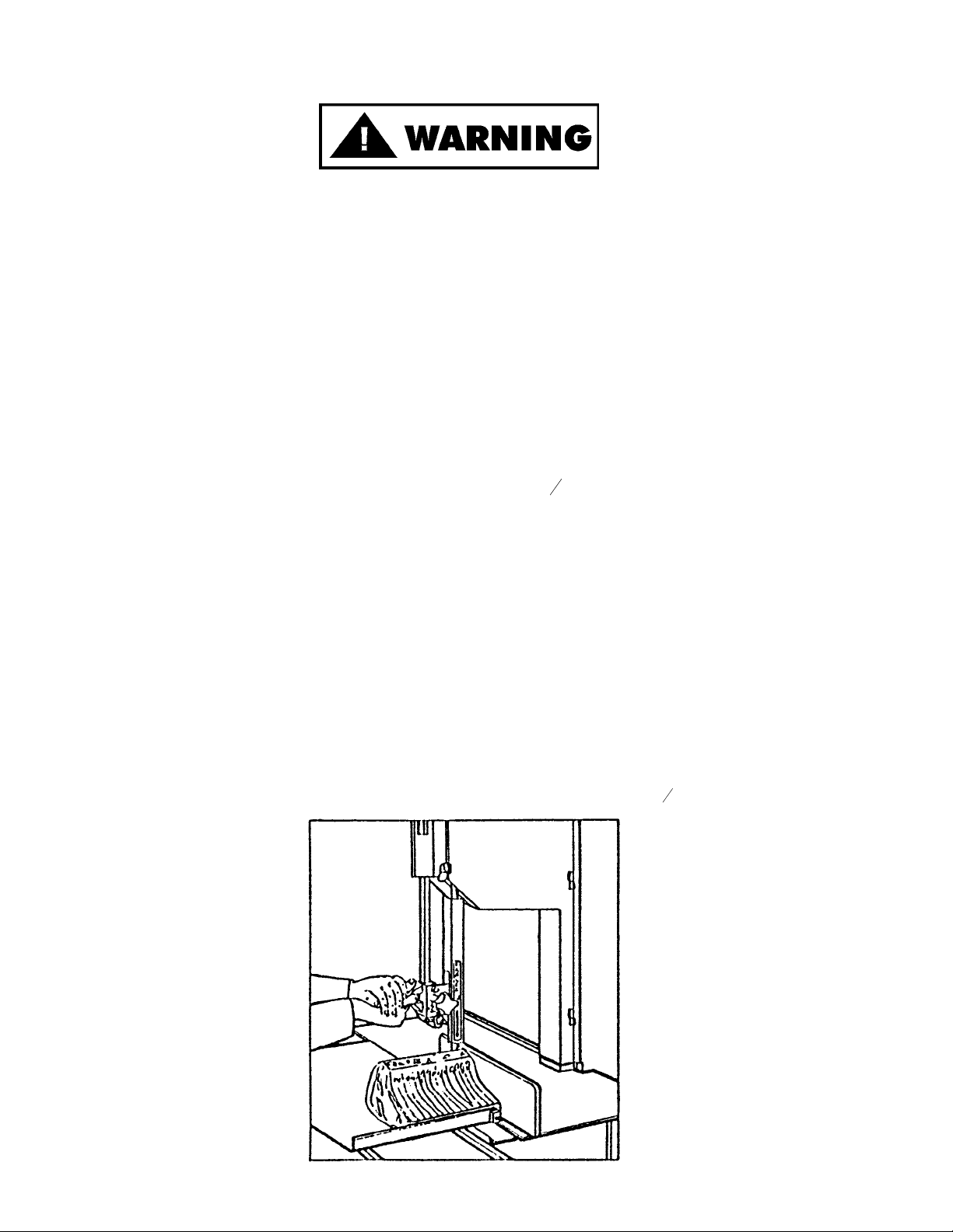
5. Standing in front of the power cutter, place product on the meat carriage. Pay attention to position of your
hands. Keep hands clear of moving band type saw blade. Leaning lightly against the scalloped front edge of
meat carriage, hold the product firmly in right hand with product face flush against meat gauge plate. Move
the meat carriage from right to left at a steady rate until fully past the saw blade. Use left hand to remove and
stack cut product, NEVER REACH IN FRONT OF BAND TYPE SAW BLADE. On the return stroke, pull
the product toward you, away from saw blade.
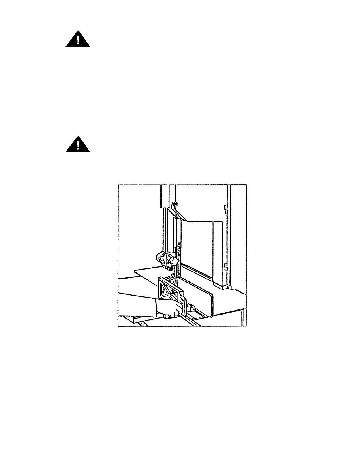
6. ALWAYS use the Safety End Cut Pusher Plate (Part No. 256P) for smaller products or the last cuts of product.
The pusher plate is supplied as standard equipment on all BIRO power saws.
7. When finished cutting, push stop button. Perform lockout/tagout procedure.
7
DO NOT WEAR GLOVES WHILE OPERATING
NEVER REACH OR GRAB FOR PRODUCT IN FRONT OF
MOVING BAND TYPE SAW BLADE
Page 10
CLEANING
SHARP MOVING BAND TYPE SAW BLADE
TO AVOID SERIOUS PERSONAL INJURY
ALWAYS Turn Off, Unplug From Power Source and Perform Lockout/Tagout Procedures to This
Machine BEFORE Removing Shrouds, Removable Guards, Covers, Doors, Fences or Panels
for Cleaning, Servicing or Any Other Reason.
ALWAYS Read Operating and Service Manual BEFORE Operating, Servicing or Cleaning.
DO NOT Alter or Modify This Machine in any Way From its Original Form. This Machine in its
Original Form Meets the Intent of O.S.H.A. Applicable Standards.
ONLY Use Recommended Cleaning Equipment, Materials and Procedures.
NEVER Spray Water or Other Liquid Substances Directly at Motor, Power Switch or any Other
Electrical Components.
ALWAYS Thoroughly Clean Equipment Daily.
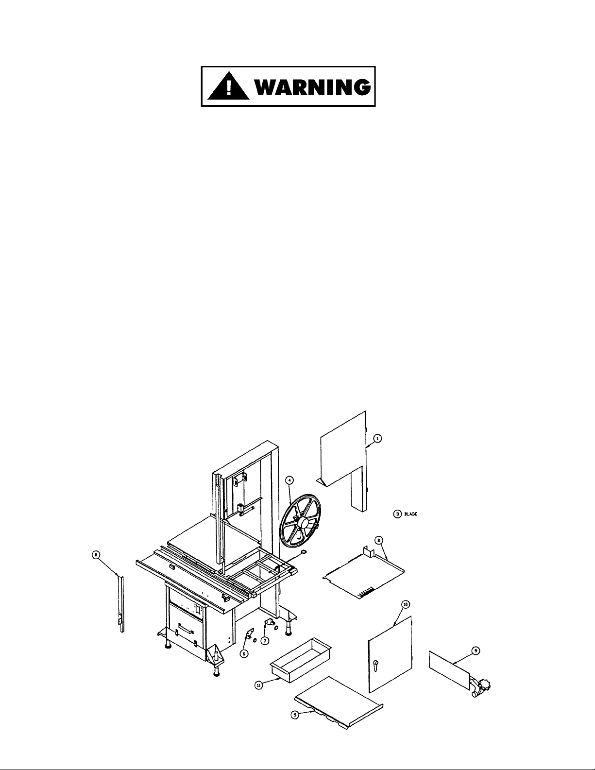
CLEANING THE BIRO POWER CUTTER:
Disconnect the electrical power from the machine before cleaning. Parts to be removed have been made accessible
and can be removed without tools. Notice the drawing below that all parts are numbered. Each part should be removed for cleaning in the numbered sequence shown. To ensure cleaner cuts, keep the cleaning system in good
condition. Parts on the cleaning system which should be checked weekly, and changed as required. See Maintenance
on pages 9 & 10.
8
Page 11

MAINTENANCE
SHARP MOVING BAND TYPE SAW BLADE
TO AVOID SERIOUS PERSONAL INJURY
ALWAYS Turn Off, Unplug From Power Source and Perform Lockout/Tagout Procedure to This
Machine BEFORE Removing Shrouds, Removable Guards, Covers, Doors, Fences or Panels
for Cleaning, Servicing or Any Other Reason.
ALWAYS Read Operating and Service Manual BEFORE Operating, Servicing or Cleaning.
NEVER Touch This Machine Without Training and Authorization By Your Supervisor.
NEVER Bypass, Alter or Modify This Machine in any Way From its Original Form. This
Machine in its Original Form Meets the Intent of O.S.H.A. Applicable Standards.
ALWAYS Keep Hands Clear of Band Type Saw Blade and Other Moving Parts.
PROMPTLY REPLACE Any Worn or Illegible Labels.
USE ONLY GENUINE BIRO Parts and Accessories Properly Installed.
A. GENERAL
1. Machine should be generally inspected every time it is cleaned (at least daily) to ensure that it is in good
condition and has not been damaged or tampered with.
a. SAW WHEELS: Clean outer diameter grooves daily. Check for cracks, gouges or wear on flange and
grooves.
DO NOT IMMERSE UPPER WHEEL ASSEMBLY IN WATER
b. WHEEL CLEANER ASSEMBLIES: Check condition of fiber cleaner, change every four (4) weeks.
c. REMOVABLE FINGER LIFT ASSEMBLY: Check condition of saw guard, make sure mounting bolts are
tight and “DANGER EXPOSED BLADE” decal is attached and legible. Check condition of upper saw
guide (Part No. 602B), replace every six (6) months. Check adjustment of upper saw guide. Should be
1
32
" between back of blade and saw guide carbide.
d. SAW GUIDE BAR: Check condition of inner and outer saw guide bar, replace as necessary. Check saw
guide bar spring for proper tension. The spring should hold the bars in any desired position in its travel.
Replace saw guide bar spring (Part No. 193) as necessary using instructions on following page.
9
NEVER USE THIS MACHINE WITHOUT PROPERLY INSTALLED
AND FUNCTIONING SAW GUIDE BAR WITH SAW GUARD
Page 12

1. Remove the finger lift fastener knob (Item No. 211A-291Q) and the finger
lift assembly (Item No. 55234).
2. Remove the finger lift fastener stud (Item No. 211D).
3. Unbolt and remove the outer saw guide bar (Item No. 55190) and the
guide bar spacer blocks (Item No. 116RS).
4. Push the inner saw guide bar (Item No. 55189) up and out of the top of the
head structure.
5. Remove the saw guide bar spring (Item No. 193).
6. Lower the new saw guide bar spring through the top of the babbitt pocket
area and guide the spring into its seating position with a standard
screwdriver. (NOTE: Drawing)
7. While holding the saw guide bar spring in position, re-enter the inner saw
guide bar from the top. Compress the saw guide bar spring slightly with
the screwdriver tip until the saw guide bar slides past the spring.
8. Replace the outer saw guide bar and spacer blocks, the finger lift fastener
stud, the fingerlift assembly and the fingerlift fastener knob.
9. Test by placing saw guide bar in several positions. Verify that it stays in
desired position.
e. STATIONARY BAR ASSEMBLY: Check condition of nylon filler (Part No. 177), change every four (4)
weeks. Check condition of saw guide (Item No. 119A), check tracking of blade through guide, back of
blade should be centered in hole, replace every six (6) months. Check condition and adjustment of lower
blade back-up guide (Part No. S608), should have
1
32
" gap between back of blade and saw guide carbide.
Replace every six (6) months.
f. SAW CLEANERS: Check condition of blade cleaners (Item No. 131), replace every four (4) weeks.
g. MEAT GAUGE ASSEMBLY: Check free movement of meat gauge arm on gear rack. Gear rack to be
kept lubricated at all times with light food grade oil. Check operation of release handle. Check that worm
gear engages properly with gear rack.
h. MEAT CARRIAGE ASSEMBLY: Check free movement through full range of travel. Check for side to
side tolerance, adjust as necessary. Check condition of and grease bearings, replace as necessary.
Check condition of thumb guard, replace as necessary.
i. SAFETY ITEMS: Check for safety end cut pusher plate is with machine and accessible. All warning
labels present, properly affixed and legible. Model and Serial Number plate properly affixed and legible.
Wall poster within operators view from machine. Operating and Service Manual accessible to operator.
B. LUBRICATION
1. UPPER WHEEL BEARINGS: Grease every four (4) months. Change grease every twelve (12) months.
2. MEAT CARRIAGE BEARINGS: Grease every four (4) weeks.
3. SAW GUIDE BAR: Oil daily with food machine oil.
4. INNER MEAT GAUGE GEAR RACK: Oil daily with food machine oil.
5. MOTOR BEARINGS: Bearing grease will lose its lubricating ability over time, not suddenly. The lubricating
ability of a grease (over time) depends primarily on the type of grease, the size of the bearing, the speed at
which the bearing operates and the severity of the operating conditions. Good results can be obtained if the
following recommendations are used in your maintenance program.
A high grade ball or roller bearing grease should be used. Recommended grease for standard service
conditions is Polyrex EM (Exxon Mobil).
Equivalent and compatible greases include: Texaco Polystar, Rykon Premium #2, Pennzoil Pen 2 Lube, and
Chevron SRI.
Recommended lubrications intervals is every 9 months with the equivalent of two (2) teaspoons of grease.
10
Page 13

C. CHANGING THE SAW BLADE
Disconnect electrical power to the machine. Move meat gauge plate to rear of machine on gear rack and turn away
from head out of the way. Open the head door fully. Pull out platter hold down rod. Remove right side platter half.
Release tension on blade, turn tensioning handle counter-clockwise. Lift nylon filler. Remove blade. Install new blade
by reversing procedure. Be sure tension mark is even with the bottom of the hinge plate for proper blade tension.
WARNING LABELS LOCATIONS
ON MODEL 55 POWER SAWS
Item No. 653PC-E Warning label,
English
1 ea. attached to head below
Model & S/N plate.
11
Item No. 653PC-E Warning label,
English
1 ea. attached to channel bracket
Item No. 653PC-SP Warning label,
Spanish
1 ea. attached to channel bracket
Item No. 708; DANGER
Exposed Blade
Attached to saw guard on
saw guide bar
Page 14

121314
Page 15

Page 16

Item No. Description
A16112 Head door latch assembly
HHS058S Hex head screw,
5
16
-18
´
7
8
,SS
HHS060S Hex head screw,
5
16
-18´1, SS
LW15S Lock washer,
5
16
,SS
SSS15 Set screw,
5
16
-18
´
5
16
,SS
112-212 Waved washer
14TH Head door hinge welded
14TP Head door hinge pin, 1
1
2
"
14TP-1 Head door hinge pin, 1
1
4
"
Item No. Description
55135 Right support angle
55136 Left support angle
55138 Hinge bracket, upper wheel
55153 Head assembly, weldment, SS
55154 Head door, SS
55191 Head & door assembly, SS
55193 Hinge bracket assembly, upper wheel
55233 Head door assembly, SS
w/VTS7181
Page 17

15
Item No. Description
AN15S Acorn nut,
1
4
-20, SS
HHS0481S Hex head screw,
1
4
-20´1
1
2
,SS
HHS124S Hex head screw,
1
2
-13
´
7
8
,SS
HN40S Hex nut,
1
2
-13 light jam, SS
LW30S Lock washer,
1
2
,SS
S18005-15 Position mount – ½ thick
S18005-16 Position mount –
11
16
thick
S18253 Upper wheel aligning screw, SS
193 Saw guide bar spring
194KS-1 Lock knob 1
1
8
196 Saw tension spring
360A1 Grease fitting
Item No. Description
55170 Blade tension cap gauge
55171-1 Blade tension adjustment housing
55172 Blade tension screw
55173 Blade tension adjustment handle
55174 Upper wheel hinge plate
55184 O-ring, blade tension screw
55192 Blade tension assembly
55194 Upper wheel assembly w/hinge plate
55312 O-ring for tension cap gauge
55313 Plastic washer – tension screw
55314 O-ring, plastic washer
Page 18

Blade Tension Screw
INSTALLATION INSTRUCTIONS
Disconnect the machine from the main power supply.
Loosen tension on the saw blade and remove the upper wheel assembly.
Unbolt the (A) tensioning handle from the (B) blade tension screw.
At the bottom handle mount turn the (B) blade tension screw clockwise until it can be lifted out of the
(C) housing.
Apply a good food grade grease to the replacement (D) tension screw and install into the (C) housing
turning counterclockwise until it bottoms out.
Replace the (A) tensioning handle. Be sure the (E) spring and (F) plunger pin are still present in the
end of the (A) handle.
Replace the upper wheel assembly and the blade.
Tension the blade.
16
(A) 55173 Tension handle
(B) 55172 Blade tension screw
(C) 55171-1 Adjustment housing
(D) 55172K Blade tension screw kit
(E) 14554 Compression spring
(F) 55178 Plunger pin
55184 O-ring, large
55313 Plastic washer
55314 O-ring, small
AN15S acorn nut, ¼-20
HHS048S Hex head screw ¼-20´1¼
Page 19

— NOTES —
17
Page 20

18
Item No. Description
A18227 Bearing cup-cone assembly
A18360 Lower bearing housing assembly w/o wheel
CB94S Carriage bolt,
3
8
-16´1
1
2
,SS
HN25S Hex nut,
3
8
-16, SS
LW25S Lock washer,
3
8
,SS
SSS05S Set screw, 10-24
´
3
8
,SS
SSS20 Set screw,
3
8
-16
´
3
8
, knurled, cup pt.
18231DL Lower shaft seal, double lip
18251AL Upper V-belt pulley, 12.8´1
1
8
, ali.
Item No. Description
18300 Lower shaft woodruff key
18360 Lower bearing housing
18361 Lower shaft
22003-6 Lower wheel, 22", 6 spoke
252X Shaft lock nut
277 Lower shaft pulley key
360A1 Grease fitting
360B-2 Adj. set screw, lwr brg hsg,
1
2
-13
´
3
4
flat pt.
362 Lower bearing housing adj. cap
Item No. Description
A18227 Bearing cup/cone assembly
A18247 Upper shaft & brg. assembly w/o wheel
A295 Wheel cleanqer assembly
HHS005S Hex head screw, 8-32
´
1
2
,SS
HHS010S Hex head screw, 10-32
´
3
8
,SS
HN05S Hex nut, 8-32, SS
HN40S Hex nut,
1
2
-13 light jam, SS
S18253 Upper wheel aligning screw, SS
S229 Wheel cleaner arm spring, SS
S244 Wheel cleaner arm stud, SS
S295 Wheel cleaner arm, SS
S325 Wheel cleaner washer, SS
Item No. Description
179 Wheel cleaner
18230DL Upper shaft seal, double lip
18247 Upper shaft
18248 Upper wheel hub cap
18252 Upper shaft lock nut
22003U-6 Upper wheel, 22", 6 spoke
234 Grease fitting
237 Upper shaft castellated lock nut
238 Upper shaft castellated lock washer
247A Upper shaft bearing back-up washer
512 Upper wheel hub cap gasket
531 Retaining ring
55174 Upper wheel hinge plate
55194 Upper wheel assembly with hinge plate
55196 Upper wheel assembly w/o hinge plate
55197 Upper wheel hinge plate assembly
Page 21

19
Item No. Description
A602 Saw guide assembly upper
FW05S Flat washer,
1
4
SS
HHS015S Hex head screw, 10-32
´
7
8
SS
HHS020S Hex head screw,
1
4
-20
´
3
8
SS
HHS085S Hex head screw,
3
8
-18´2SS
HN10S Hex nut, 10-32 SS
LW05S Lock washer, #10 SS
LW10S Lock washer,
1
4
,SS
LW15S Lock washer,
5
16
,SS
RHS10S Round head screw, 10-32
´
3
4
SS
RHS30S Round head screw,
1
4
-20
´
7
8
SS
116RS Spacer, double saw guide bar
17211-22 Shim, .022
17211-35 Shim, .035
193 Saw guide bar spring
211 Finger lift
211A-291Q Finger lift fastener knob, 4 point
211D Finger lift fastener bolt
55140 Saw guard w/708 DANGER decal
55189-1 Saw guide bar, inner, 32"
55190-1 Reinforcement bar, outer, 30"
55234 Finger lift assembly, removable
55235 Saw guide bar assembly, double
601 Upper saw guide bracket
602B Upper saw guide
708 Decal, “DANGER EXPOSED BLADE”
Item No. Description
A18275 Meat gauge plate assembly
A262 Release handle assembly
FW10S Flat washer,
5
16
,SS
HHS040S Hex head screw,
1
4
-20
´
3
4
,SS
HHS060S Hex head screw,
5
16
-18´1, SS
HN20S Hex nut,
5
16
-18, SS
LW10S Lock washer,
1
4
,SS
LW15S Lock washer,
5
16
,SS
S235 Taper pin, 4
´
3
4
,SS
S262 Release handle, SS
S265 Meat gauge release spring, SS
18275 Meat gauge arm
18275-2 Meat gauge plate, SS
264G Meat gauge hand wheel groove pin
264-1 Meat gauge release hand wheel
Item No. Description
267 Meat gauge release cotter key
270 Meat gauge release pin
271 Meat gauge worm gear
272-7-1 Lock knob,
5
16
-18, 3 point
272-8 Cap nut,
5
16
-18, SS
272-9 Hex head screw,
5
16
-18´2, SS
272-12 Brass ball,
7
32
dia.
272-13 Hex head screw,
5
16
-18´1
1
4
,SS
272-14 Castle nut,
5
16
-18, SS
275THS Truss head screw,
1
4
-20
´
3
8
275THS-1 Truss head screw,
1
4
-20´1
55182 Meat gauge bracket
55185 Meat gauge gear rack
55236 Meat gauge assembly
55237 Meat gauge bracket assembly
Page 22

20
Item No. Description
AS415D Stationary bar assembly
HHS025S Hex head screw,
1
4
-20
´
1
2
,SS
LW10S Lock washer,
1
4
SS
S268 Stationary bar headless screw
119A Saw guide in stationary bar
177 Nylon filler
S415D Stationary bar
Item No. Description
AS12132 Rear cleaning unit assembly
HHS003S Hex head screw, 8-32
´
1
4
SS
HHS055S Hex head screw,
5
16
-18
´
3
4
SS
LW15S Lock washer,
5
16
,SS
S12132 Rear blade cleaning unit
S235 Taper pin, 4
´
3
4
,SS
131 Saw cleaner, SS
211Q Fastener knob,
5
16
-18, 4 point
Item No. Description
A295 Wheel cleaner assembly
HHS003S Hex head screw, 8-32
´
1
4
SS
HHS005S Hex head screw, 8-32
´
1
2
,SS
HHS009S Hex head screw, 10-24´¼SS
HHS055S Hex head screw,
5
16
-18
´
3
4
SS
HN05S Hex nut, 8-32, SS
LW15S Lock washer,
5
16
,SS
S229 Wheel cleaner arm spring, SS
S235 Taper pin, 4
´
3
4
,SS
S244 Wheel cleaner arm shoulder bolt, SS
S295 Wheel cleaner arm, SS
S325 Wheel cleaner arm washer, SS
S608 Back-up guide, carbide
131 Saw cleaner, SS
14640 Wheel cleaner, Rulon
179 Wheel cleaner
211Q Fastener knob,
5
16
-18, 4 point
55114-1 Lower front cleaning unit, weldment
55241-1 Lower front cleaning unit assembly
Item No. Description
AS415D-2 Stationary bar assembly
HHS025S Hex head screw,
1
4
-20
´
1
2
,SS
LW10S Lock washer,
1
4
SS
S268 Stationary bar headless screw
119A Saw guide in stationary bar
177 Nylon filler
S415D-2 Stationary bar, SS
S608 Back-up guide, carbide
SSS04S Set screw, cup point 10-24
´
1
4
SS
Page 23

21
Item No. Description
A16200 Channel stop assembly, movable
A16220-1 Channel stop assembly, fixed
FW08S Flat washer,
3
8
,SS
FW15S Flat washer,
1
2
,SS
HHS055S Hex head screw,
5
16
-18
´
3
4
,SS
HHS075S Hex head screw,
3
8
-16´1
1
4
,SS
HN25S Hex nut,
3
8
-16, SS
LW15S Lock washer,
5
16
,SS
LW25S Lock washer,
3
8
heavy, SS
S200B1 Carriage stop stud, SS
Item No. Description
CB94S-1 Carriage bolt, flat head
3
8
-16´1½, SS
16200 Carriage stop, movable
16220-1 Carriage stop, fixed
18120EZ-B3 Guide bar, EZ flow
310 Waved washer
311 Rubber bumper for stops
311-1 Rubber bumper for movable stop
376 Drive screw, #10
´
1
2
,SS
55126 Channel, EZ flow
55186 Channel assembly, EZ flow
Item No. Description
A175S Thumb guard assembly, NSS
AN15S Acorn nut,
1
4
-20, SS
FW05S Flat washer,
1
4
,SS
HN25S Hex nut,
3
8
-16, SS
LW20S Lock washer,
3
8
,SS
S155EZ-1 Weld stud,
1
4
-20
´
3
8
,SS
S155EZ-2 Weld stud,
3
8
-16
´
1
2
,SS
S155EZ-3 Hex stand-off
S155-11 Meat carriage stop thumb screw, SS
Item No. Description
16155-13 Carriage stop angle, SS
16159 Meat carriage bearing, SS
175S Thumb guard
175-1-S Thumb guard nut, SS
175-2-S Thumb screw, SS
55127 Meat carriage angle, EZ flow
55128 Meat carriage top only
55180 Carriage stop
55216 Meat carriage assembly
Page 24

22
Item No. Description
HHS070S Hex head screw,
3
8
-16´1, SS
HHS125S Hex head screw,
1
2
-13´1, SS
HN31S Hex nut,
3
8
-16, SS
HN43S Hex nut,
1
2
-13, SS
LW20S Lock washer,
3
8
,SS
LW30S Lock washer,
1
2
,SS
SSS20 Set screw,
3
8
-16
´
3
8
, knurled pt.
221-68 V-belt, 68"
221-70 V-belt, 70"
4-401AL Motor pulley, 5´1
1
8
, ali.
55107 Channel bracket, right side
55108 Channel bracket, left side
55109 Channel bracket, top
55111 Front panel – channel bracket
55121 Bottom support weldment, DNS
55123 Motor mount weldment
55125 Pivot block, motor mount
55134 Motor, Baldor 5HP,
208-230/460-60-3
55134-WEG Motor, WEG 5HP,
208-230/460-60-3/TE
55134-575 Motor, Baldor 5HP, 575-60-3/TE
55137 Adjustment stud, motor mount
55179 Support, channel brkt. front panel
55187 Channel brkt. & motor comp.
assembly
Item No. Description
AS415D Stationary bar assembly
HHS025S Hex head screw,
1
4
-20
´
1
2
,SS
LW10S Lock washer,
1
4
,SS
MC-10E Cotter key,
1
8
´
1
S268 Stationary bar headless screw, SS
Item No. Description
S415D Stationary bar, SS
119A Saw guide in stationary bar
177 Nylon filler
55291 Platter, right top
55309 Platter, left top
18212W Platter rod
Item No. Description
HHS070S Hex head screw,
3
8
-16´1, SS
HHS125S Hex head screw,
1
2
-13´1, SS
HN31S Hex nut,
3
8
-16, SS
HN43S Hex nut,
1
2
-13, SS
LW20S Lock washer,
3
8
,SS
LW30S Lock washer,
1
2
,SS
SSS20 Set screw,
3
8
-16
´
3
8
, knurled pt.
221-68 V-belt, 68"
221-70 V-belt, 70"
4-401AL Motor pulley, 5´1
1
8
, ali.
55107 Channel bracket, right side
55108 Channel bracket, left side
55109 Channel bracket, top
55111 Front panel – channel bracket
55121 Bottom support weldment, DNS
55123 Motor mount weldment
55125 Pivot block, motor mount
55134 Motor, Baldor 5HP,
208-230/460-60-3
55134-WEG Motor, WEG 5HP,
208-230/460-60-3/TE
55134-575 Motor, Baldor 5HP, 575-60-3/TE
55137 Adjustment stud, motor mount
55179 Support, channel brkt. front panel
55187 Channel brkt. & motor comp.
assembly
55115
HHS080S
HHS080S Hex head screw, 3⁄8 -16 x 1 1⁄2 SS
55115 Front spacer
Page 25

23
Item No. Description
A16226A-SG GR/RD palm button assembly
HHS041S Hex head screw,
1
4
-28
´
1
2
,SS
HHS070S Hex head screw,
3
8
-16´1, SS
HN05S Hex nut, 8-32, SS
HN20S Hex nut,
5
16
-18, SS
H462 Switch guard
H462-1 Switch guard ferrule
LW03S Lock washer, #8, SS
LW15S Lock washer,
5
16
,SS
LW20S Lock washer,
3
8
,SS
RHS075S Roundhead screw, 8-32
´
3
4
,SS
151 Watertight conduit´15½"
16226A-6 Palm button speed nut
224-1 Conduit connector, straight, WT
225-1 Conduit connector, 90 deg., WT
226-28 Connector washer
226EE-540 Switch assembly, 5HP, 208/220-60-3
226EE-544 Switch assembly, 5HP, 440-60-3
226EE-548 Switch assembly, 5HP, 575-60-3
241GR Green #12 wire´33½"
241WH White #12 wire´33½"
375 Rivet
653PC-E Warning label, English
653PC-SP Warning label, Spanish
55107 Channel bracket, right side
55110 Control panel, channel bracket
55133 Switch bracket before SR No. 55059
55188 Switch mounting bracket assembly
55327 Switch bracket starting with
Serial No. 55059
NOT SHOWN
226EE-C011K Contactor, LS11K.10-C0, 208/220V
226EE-E0 Contactor, LS05.10-E0, 440V
226EE-F0 Contactor, LS05.10-F0, 575V
226EE-OL08L Overload, B17S-M, (5.5-8)
226EE-OL18O Overload, B17S-O, (14.5-18)
Page 26

OPTIONAL DOUBLE ROLLING TABLES
24
Item No. Description
A36-2001 Carriage stop assembly, movable
A36-2002 Carriage stop assembly, fixed
FW08S Flat washer,
3
8
,SS
FW15S Flat washer,
1
2
,SS
HHS025S Hex head screw,
1
4
-20
´
1
2
,SS
HHS041S Hex head screw,
1
4
-28
´
1
2
,SS
HHS055S Hex head screw,
5
16
-18
´
3
4
,SS
HHS070S Hex head screw,
3
8
-16´1, SS
HN15S Hex nut,
1
4
-20, SS
HN20S Hex nut,
5
16
-18, SS
HN25S Hex nut,
3
8
-16, SS
HN30S Hex nut,
3
8
-16 light jam, SS
HN35S Hex nut,
3
8
-16, heavy jam, SS
LW10S Lock washer,
1
4
,SS
LW15S Lock washer,
5
16
,SS
LW20S Lock washer,
3
8
,SS
LW25S Lock washer,
3
8
heavy, SS
S155EZ-2 Weld stud,
3
8
-16
´
1
2
S155EZ-3 Hex stand-off
S235 Taper pin, 4
´
3
4
,SS
S360CB-1 Carriage bolt,
3
8
-16´1
1
4
,SS
16015-3 Motor base plate wing nut
16159 Meat carriage bearing, SS
18120EZ-B3 Guide bar, EZ flow
18D9239-4 Left rear bearing angle
18D9239-5 Left front bearing angle
296-800H Switch bracket
375 Drive screw
Item No. Description
376 Drive screw, #10
´
1
2
,SS
50655-1 Pushbutton switch guard
55121 Bottom support weldment, DNS
55198 Bearing angle, right rear
55199 Bearing angle, right front
55200 Rear meat carriage, dbl rolling tables
55203 Front meat carriage, dbl rolling tables
55204 Rim extension, right
55205 Front box channel, dbl rolling tables
55206 Channel bracket, right side, dbl rolling tables
55207 Channel bracket, left side, dbl rolling tables
55208 Pan angle, front meat carriage
55210 Tie bar, left
55211 Tie bar, right
55212 Top front panel, channel bracket
55213 Filler plate with neck guard,
dbl rolling tables
55304 Saw guard w/708 Danger decal for double
rolling tables
653PC-E Warning label, English
653PC-SP Warning label, Spanish
800H-2HA4 Watertight start/stop station, SS enclosure
NOT SHOWN
226EE-605 Switch assembly 5HP, 208/230-60-3
226EE-C011K Contactor, LS11K.10-C0, 208/230
226EE-0L18O Overload, B18K-O (14.5-18)
Page 27

OPTIONAL FIXED FRONT FULL LENGTH TABLE
25
Item No. Description
AS415D Stationary bar assembly
A16220-1 Carriage stop assembly, fixed
FW08S Flat washer,
3
8
,SS
HHS025S Hex head screw,
1
4
-20
´
1
2
,SS
HHS055S Hex head screw,
5
16
-18
´
3
4
,SS
HHS070S Hex head screw,
3
8
-16´1, SS
HN25S Hex nut,
3
8
-16, SS
LW10S Lock washer,
1
4
,SS
LW15S Lock washer,
5
16
,SS
LW25S Lock washer,
3
8
heavy, SS
MC-10E Cotter key,
1
8
´
1
S268 Stationary bar headless screw
Item No. Description
CB94S-1 Carriage bolt, flat head
3
8
-16´1½, SS
S415D Stationary bar, SS
119A Saw guide in stationary bar
16220-1 Carriage stop, fixed
177 Nylon filler
311 Rubber bumper
376 Drive screw, #10
´
1
2
,SS
55126-FT Channel, for fixed front table
55309 Left top platter assembly
18212W Platter rod
55177 Front stationary table assembly
55317 Right top fixed table, platter
Page 28

MODEL 55 ITEM NUMBERS AND DESCRIPTIONS
ALWAYS ADVISE MODEL & SERIAL NUMBER WHEN ORDERING
26
Item No. Description
AN15S Acorn nut,
1
4
-20, SS
CB64S Carriage bolt,
1
4
-20´1
1
2
,SS
FW05S Flat washer,
1
4
,SS
FW08S Flat washer,
3
8
,SS
FW10S Flat washer,
5
16
,SS
FW15S Flat washer,
1
2
,SS
HHS003S Hex head screw, 8-32
´
1
4
,SS
HHS005S Hex head screw, 8-32
´
5
8
,SS
HHS009S Hex head screw, 10-24´¼SS
HHS010S Hex head screw, 10-32
´
3
8
,SS
HHS015S Hex head screw, 10-32
´
7
8
,SS
HHS020S Hex head screw,
1
4
-20
´
3
8
,SS
HHS025S Hex head screw,
1
4
-20
´
1
2
, SS
HHS040S Hex head screw,
1
4
-20
´
3
4
,SS
HHS041S Hex head screw,
1
4
-28
´
1
2
,SS
HHS0481S Hex head screw,
1
4
-20´1
1
2
,SS
HHS055S Hex head screw,
5
16
-18
´
3
4
,SS
HHS058S Hex head screw,
5
16
-18
´
7
8
,SS
HHS060S Hex head screw,
5
16
-18´1, SS
HHS070S Hex head screw,
3
8
-16´1, SS
HHS075S Hex head screw,
3
8
-16´1
1
4
,SS
HHS085S Hex head screw,
3
8
-16´2, SS
HHS110S Hex head screw,
1
2
-20´1, SS
HHS125S Hex head screw,
1
2
-13´1, SS
HN05S Hex nut, 8-32, SS
HN10S Hex nut, 10-32, SS
HN15S Hex nut,
1
4
-20, SS
HN20S Hex nut,
5
16
-18, SS
HN25S Hex nut,
3
8
-16, SS
HN30S Hex nut,
3
8
-16 light jam, SS
HN31S Hex nut,
3
8
-16, SS
HN35S Hex nut,
3
8
-16 heavy jam, SS
HN40S Hex nut,
1
2
-13 light jam, SS
HN43S Hex nut, ½-13, SS
HN45S Hex nut,
1
2
-20, SS
HN49 Hex nut,
5
8
-11, plated
HN55S Hex nut,
5
8
-18 jam, SS
H462 Switch guard
H642-1 Switch guard ferrule
LW05S Lock washer, #10, SS
LW10S Lock washer,
1
4
,SS
LW15S Lock washer,
5
16
,SS
LW20S Lock washer,
3
8
,SS
LW25S Lock washer,
3
8
heavy, SS
LW30S Lock washer,
1
2
,SS
LW35S Lock washer,
5
8
,SS
MC-10E Cotter pin,
1
8
´
1, SS
RHS075S Round head screw, 8-32
´
3
4
,SS
RHS10S Round head screw, 10-32
´
3
4
,SS
RHS30S Round head screw,
1
4
-20
´
7
8
,SS
SSS04S Set screw, 10-24
´
1
4
, cone point, SS
SSS05S Set screw, 10-24
´
3
8
, cup point, SS
SSS20 Set screw,
3
8
-16
´
3
8
, knurled cup point, SS
S12132 Rear blade cleaning unit
S155EZ-1 Weld stud,
1
4
-20
´
3
8
,SS
S155EZ-2 Weld stud,
3
8
-16
´
1
2
,SS
S155EZ-3 Hex stand-off
S18253 Upper wheel aligning screw, SS
S200B1 Stop stud, SS
S229 Wheel cleaner arm spring, SS
S235 Taper pin, 4
´
3
4
,SS
S244 Wheel cleaner arm shoulder bolt, SS
S262 Meat gauge release handle, SS
S265 Meat gauge release spring, SS
S268 Stationary bar headless screw, SS
S295 Wheel cleaner arm, SS
S325 Wheel cleaner washer, SS
CB94S-1 Carriage bolt, flat head
3
8
-16´1½, SS
S415D Stationary bar, SS
S608 Back up guide, carbide
TP4S Taper pin, 4
´
3
4
,SS
TP6S Taper pin, 6
´
3
4
,SS
VT460S Model & S/N plate
112-212 Waved washer
116RS Saw guide bar spacer block
119A Saw guide in stationary bar
131 Saw cleaner, SS
14TH Head door hinge, welded
14TP Head door hinge pin, long
Item No. Description
14TP-1 Head door hinge pin, short
14640 Wheel cleaner, rulon
151 WT conduit
16015-3 Motor base plate wing nut
16155-13 Carriage stop angle, SS
16159 Meat carriage bearing, SS
16200 Movable carriage stop
16220-1 Fixed carriage stop
16226A-6 Palm button speed nut
17211-22 Fingerlift shim, .022
17211-35 Fingerlift shim, .035
175S Thumb guard
175-1-S Thumb guard nut, SS
175-2-S Thumb screw
177 Nylon filler
179 Wheel cleaner
18D9239-4 Left rear bearing angle
18D9239-5 Left front bearing angle
18120EZ-B3 Guide bar, EZ flow
18212W Platter rod
18230DL Upper shaft seal, double lip
18231DL Lower shaft seal, double lip
18247 Upper shaft
18251AL Upper v-belt pulley, 12.8´1
1
8
, ali.
18252 Upper shaft lock nut
18275 Meat gauge arm
18275-2 Meat gauge plate only, SS
18300 Lower shaft woodruff key
18360 Lower bearing housing
18361 Lower shaft
193 Saw guide bar spring
194KS-1 Lock knob – 1
1
8
"
196 Tension spring
211 Finger lift
211A-291Q Fastener knob,
3
8
-16, 4 point
211D Finger lift fastener stud
211Q Fastener knob,
5
16
-18, 4 point
22003-6 Lower wheel, 22", 6 spoke
22003U-6 Upper wheel, 22", 6 spoke
221-68 V-belt, 68"
221-70 V-belt, 70"
224-1 Conduit connector, straight, WT
225-1 Conduit connector, 90 deg., WT
226-28 Connector washer
226EE-C011K Contactor, LS11K.10-C0, 208/220V
226EE-E0 Contactor, LS05.10-E0, 440V
226EE-OL08L Overload, B17S-M, (5.5-8)
226EE-OL18O Overload, B17S-O, (14.5-18)
226EE-540 Magnetic starter, 5HP, 208/220-60-3
226EE-544 Magnetic starter, 5HP, 440-60-3
226EE-548 Switch assembly, 5HP, 575-60-3
226EE-605 Switch assembly 5HP, 208/230-60-3
for double rolling tables
234 Grease fitting
237 Upper shaft castellated lock nut
238 Upper shaft castellated lock washer
241GR Green wire, 12 ga.
241WH White wire, 12 ga.
247A Upper shaft bearing spacer washer
249 Door lock handle
252X Shaft lock nut
256P Safety end cut pusher plate
264G Meat gauge hand wheel groove pin
264-1 Meat gauge release hand wheel
267 Meat gauge release cotter pin
270 Meat gauge release pin
271 Meat gauge worm gear
272-7-1 Lock knob,
5
16
-18, 3 point
272-8 Cap nut,
5
16
-18, SS
272-9 Hex head screw,
5
16
-18´2, SS
272-12 Brass ball,
7
32
272-13 Hex head bolt,
5
16
-18´1
1
4
,SS
272-14 Castle nut,
5
16
-18, SS
275THS Truss head screw,
1
4
-20
´
3
8
275THS-1 Truss head screw,
1
4
-20´1
296-800H Pushbutton switch bracket
310 Waved washer
311 Rubber bumper
311-1 Rubber bumper
Page 29

MODEL 55 ITEM NUMBERS AND DESCRIPTIONS (Cont.)
27
ASSEMBLIES FOR MODEL 55
Item No. Description
AS12132 Rear cleaning unit assembly
AS415D Stationary bar assembly
A16112 Head door latch assembly
A16200 Carriage stop assembly, movable
A16220-1 Carriage stop assembly, fixed
A16226A-SG Palm button assembly
A175S Thumb guard assembly
A18227 Bearing cup/cone assembly
A18247 Upper shaft & bearing assembly
A18275 Meat gauge plate assembly
A262 Meat gauge release assembly
A295 Wheel cleaner assembly
A36-2001 Carriage stop assembly, dbl rolling tables
A36-2002 Carriage stop assembly, dbl rolling tables
A602 Upper guide assembly
55164 Left top platter assembly
55186 Channel assembly, EZ flow
Item No. Description
55187 Channel brkt & motor comp. assembly
55191 Head & door assemlby
55192 Blade tension assembly
55193 Hinge bracket assembly, upper wheel
55194 Upper wheel assembly w/hinge plate
55196 Upper wheel assembly w/o hinge plate
55197 Upper hinge plate assembly
55216 Meat carriage assembly, EZ flow
55233 Head door assembly
55234 Finger lift assembly, removable
55235 Saw guide bar assembly, double
55236 Meat gauge assembly
55237 Meat gauge bracket assembly
55238 Platter assembly
55241-1 Front cleaning unit assembly
55242 Lower bearing housing assembly w/o wheel
55243 Opt. fixed table assembly
Item No. Description
36A1 Grease fitting
360B-2 Set screw,
1
2
-13
´
3
4
, flat point
362 Bearing adjusting cap
36-239LN Locknut, 1
1
4
-12, SS
36-239L-10A Solid leg, 10", SS
36-242R Base door lock
375 Drive screw
376 Drive screw, #10
´
1
2
,SS
4-401AL Motor pulley, 5´1
1
8
, ali
50655 Switch guard
512 Upper wheel hub gasket
531 Retaining ring
55100-1 Base frame assembly
55102 Basefoot outrigger angle, rear, 30"
55104 Base door, right hinged
55105 Left panel w/handle
55106 Scrap bucket
55107 Channel bracket, right side
55108 Channel bracket, left side
55109 Channel bracket, top
55110 Control panel, channel bracket
55111 Front panel – channel bracket
55114-1 Lower cleaning unit weldment
55121 Bottom support weldment, DNS
55123 Motor mount weldment
55125 Pivot block, motor mount
55126 Channel, EZ flow
55126-FT Channel, fixed front table
55127 Meat cariage angle, EZ flow
55128 Meat carriage top only
55131 Platter, right top
55133 Switch bracket before SR No. 55059
55134 Motor, Baldor 5HP, 208-220/440-60-3
55134-WEG Motor, WEG 5HP, 208-230/460-60-3/TE
55134-575 Motor, Baldor 5HP, 575-60-3/TE
55137 Adjustment stud, motor mount
55138 Upper wheel hinge bracket
55140 Saw guard on saw guide bar w/708 decal
55153 Head weldment
55154 Head door
55165 Platter rod, RH platter top
55168 Thread, head column
55170 Blade tension cap gauge
55171 Blade tension adjustment housing
Item No. Description
55172 Blade tension screw
55173 Blade tension adjustment handle
55174 Upper wheel plate
55177 Front stationary table assembly
55179 Support, channel bracket front panel
55180 Carriage stop
55181 Base foot outrigger, front
55182 Meat gauge bracket
55184 O-Ring, blade tension screw
55185 Meat gauge gear rack
55189 Saw guide bar, 32"
55190 Reinforcement bar, 30"
55195 Right top fixed table, platter
55198 Bearing angle, right rear
55199
Bearing angle, right front
55200 Rear meat carriage, dbl rolling tables
55203 Front meat carriage, dbl rolling tables
55204 Rim extension, right
55205 Front box channel, dbl rolling tables
55206 Channel bracket, right side, dbl rolling tables
55207 Channel bracket, left side, dbl rolling tables
55208 Pan angle, front meat carriage
55210 Tie bar, left
55211 tie bar, right
55212 Top front panel, channel bracket
55213 Filler plate, dbl rolling tables
55220 Motor mount support, LH
55290 Platter bracket
55302HT Saw blade, 164-
123
4
´
X .022 HT, 3TPI
55291 Platter – right top
55309 Platter – left top
55312 O-ring for tension cap gauge
55313 Plastic washer – tension screw
55314 O-ring – plastic washer
55317 Platter – right top fixed table
55327 Switch bracket starting with Serial No. 55059
601 Upper saw guide bracket
602B Upper blade back-up guide, carbide
653PC-E Warning label, English
653PC-F Warning label, French
653PC-SP Warning label, Spanish
671 Wall poster
708 Decal “DANGER EXPOSED BLADE”
800H-2HA4 WT start/stop station, SS
Page 30

WEARABLE SAW PARTS THAT WILL FIT BIRO POWER CUTTERS
MODELS
11-22-1433-33-34-3334-44-4436-55
— EXCEPT WHERE NOTED OTHERWISE —
CONTACT YOUR NEAREST BIRO AUTHORIZED DISTRIBUTOR
OR CONTACT BIRO MANUFACTURING
Ph. 419-798-4451 E-Mail: service@birosaw.com
28
Page 31

OPERATOR'S SIGNATURE PAGE
MY SIGNATURE ATTESTS THAT I HAVE COMPLETELY READ AND UNDERSTAND THIS
MANUAL. I REALIZE THAT THIS MACHINE, IF OPERATED CARELESSLY, CAN CAUSE SERIOUS INJURY TO MYSELF AND OTHERS.
NAME (PRINT) SIGNATURE
SUPERVISOR’S
INITIALS
DATE
29
Page 32

LIMITED WARRANTY:
WARRANTY: The BIRO Manufacturing Company warrants that Model 55 Power Meat Saw will be free
from defects in material and workmanship under normal use and with recommended service. BIRO
will replace defective parts, which are covered by this limited warranty, provided that the defective parts
are authorized for return, shipping charges prepaid, to a designated factory for inspection and/or testing.
DURATION OF WARRANTY: The warranty period for all parts covered by this limited warranty is
eighteen (18) months from Inspection/Demonstration as advised on the returned Warranty Registration
card, or two (2) years from original factory ship date, whichever occurs first, except as noted.
PARTS NOT COVERED BY WARRANTY: The following are not covered by this limited warranty:
steel cleaners, item number 131; wheel cleaners, item number 179; steel guide, item number 119A;
upper saw guide, item number 602B; lower back guide, item number S608; nylon filler, item number
177. This limited warranty does not apply to machines sold as used, rebuilt, modified,or altered from
the original construction in which the machine was shipped from the factory. (WATER CONTAMINATED ELECTRICAL SYSTEMS ARE NOT COVERED UNDER THIS LIMITED WARRANTY.) BIRO is
not responsible for electrical connection of equipment, adjustments to switch controls or any other
electrical requirements, which must be performed only by a certified electrician. BIRO is not responsible for service charges or labor required to replace any part covered by this limited warranty or for any
damages resulting from misuse, abuse, lack of proper or recommended service.
EXCLUSION OF WARRANTIES AND LIMITATION OF REMEDIES: BIRO gives no warranties other
than those expressly stated in this limited warranty. THE IMPLIED WARRANTY OF MERCHANTABILITY, THE IMPLIED WARRANTY OF FITNESS FOR PROCESSING OF FOOD PRODUCTS, AND ALL
OTHER IMPLIED WARRANTIES ARE SPECIFICALLY EXCLUDED. BIRO IS NOT LIABLE FOR CONSEQUENTIAL OR INCIDENTAL DAMAGES, EXPENSES, OR LOSSES. THE REMEDIES PROVIDED
IN THIS BIRO LIMITED WARRANTY ARE PURCHASER’S SOLE AND EXCLUSIVE REMEDIES
AGAINST BIRO.
REGISTRATION CARDS: You must sign, date and complete the warranty registration card supplied
with each machine. The warranty card must be returned to The Biro Manufacturing Company for
proper registration. If no warranty card is returned to BIRO, the warranty period will begin from the
date the machine was originally shipped from the factory.
HOW TO GET SERVICE:
1. Contact the agency from whom you purchased the machine.
2. Consult the yellow pages of the phone directory for the nearest authorized dealer.
3. Contact BIRO Mfg. Co. for the authorized service entity (250 plus worldwide) in your area.
THE BIRO MANUFACTURING COMPANY
1114 Main Street
Marblehead, Ohio 43440-2099
Ph. 419-798-4451
Fax 419-798-9106
E-mail: service@birosaw.com
Web: http://www.birosaw.com
30
ITEM No.: 55221-284
PTCT Md 55-284-11-06-4 COMM
ITEM No.: 55221-284
PTCT Md 55-284-4-08-5 PPD
 Loading...