

Page 1

+
IMPORTANT NOTICE
+
This Manual contains important
safety instructions which must
be strictly followed when using
this equipment.
PTCT 3334
100-5-06-29
PTCT 3334
100-10-09-31
Page 2

TABLE OF CONTENTS
Page
NOTICETOOWNERSANDOPERATORS......................................... 1
SAFETYTIPS............................................................... 2
INSTALLATION ............................................................. 3
WARNINGLABELS........................................................... 5
OPERATION................................................................ 6
TOPROCESSPRODUCT............................................... 6&7
CLEANING................................................................. 8
MAINTENANCE ............................................................. 9
GENERAL .............................................................. 9
LUBRICATION...........................................................10
WALLCHART(PARTNo.671) ..............................................11
MOTORADJUSTMENT....................................................12
SAWGUIDEBARANDSAWGUARD .....................................12&13
PARTSDIAGRAMS...........................................................14
PARTS DIAGRAMS, SERIES 4003 CARRIAGE & CHANNEL . . . . . . . . . . . . . . . . . . . . . . 21,22,23
MOTORCOVERAPPLICATIONS ................................................24
PARTSDIAGRAMS,LOWERREMOVABLEWHEEL ..................................24
LOWER REMOVABLE WHEEL INSTALLATION AND REMOVAL INSTRUCTIONS . . . . . . . . . . . 25
SWITCHASSEMBLIESANDSERVICEPARTS..................................26&27
WIRINGDIAGRAMS ....................................................28,29,30
PARTSLIST/ORDERING ..................................................30&31
PARTSASSEMBLIESLIST/ORDERING ...........................................32
STAINLESSSTEELHEADSTRUCTUREHISTORY...................................32
WEARABLESAWPARTS ......................................................33
WARNINGLABELLOCATIONSONMACHINE .................................34&35
NOTES....................................................................36
OPERATOR’SSIGNATUREPAGE................................................37
LIMITEDWARRANTY.........................................................38
WIRING DIAGRAMS........... .................................28-34
PARTS LIST/ORDERING. ...................................... 35 & 36
PARTS ASSEMBLIES LIST / ORDERING ................................. 37
STAINLESS STEEL HEAD STRUCTURE HISTORY . . . . . . . . . . . . . . . . . . . . . . . . . 37
WEARABLE SAW PARTS . ........................................... 38
WARNING LABEL LOCATIONS ON MACHINE . . . . . . . . . . . . . . . . . . . . . . . 39 & 40
OPERATOR’S SIGNATURE PAGE. ..................................... 41
LIMITED WARRANTY . ............................................ 42
Page 3

NOTICE TO OWNERS AND OPERATORS
BIRO’s products are designed to process food products safely and efficiently. Unless the operator is properly trained and supervised, however, there is the possibility of a serious injury. It is the
responsibility of the owner to assure that this machine is used properly and safely, strictly following
the instructions contained in this Manual and any requirements of local law.
No one should use or service this machine without proper training and supervision. All operators should be thoroughly familiar with the procedures contained in this Manual. Even so BIRO
cannot anticipate every circumstance or environment in which its products will be used. You, the
owner and operator, must remain alert to the hazards posed by the function of this equipment –
particularly the SHARP MOVING BAND TYPE SAW BLADE. No one under eighteen (18) years of
age should operate this equipment. If you are uncertain about a particular task, ask your supervisor.
This Manual contains a number of safe practices in the SAFETY TIP section. Additional warnings are placed throughout the Manual. Warnings related to your personal safety are indicated by:
Warnings related to possible damage are indicated by:
BIRO also has provided a wall chart to be posted near the equipment. If any warning label, wall
chart, or Manual becomes misplaced, damaged, or illegible, please contact your nearest Distributor or BIRO directly for a replacement.
Remember, however, this Manual or the warning labels do not replace the need to be alert and
to use your common sense when using this equipment.
This Manual applies to machines with serial number 1,000 and higher.
1
OR
– NOTE –
A copy of this manual is included with each
MODEL 3334 & 3334-4003 POWER MEAT SAW.
The descriptions and illustrations contained in this manual are not binding.
The manufacturer reserves the right to introduce any modification without
updating the manual.
Page 4

SAFETY TIPS
SHARP MOVING BAND TYPE SAW BLADE
TO AVOID SERIOUS PERSONAL INJURY
NEVER Touch This Machine Without Training and Authorization By Your Supervisor.
ALWAYS Read Operation and Parts Manual BEFORE Operating, Cleaning or Servicing.
ALWAYS Keep Hands Clear of Sharp Band Type Saw Blade and Other Moving Parts.
ONLY Use a Qualified Electrician to Install According to Local Building Codes: Machines MUST
Be Properly Grounded.
ONLY Install on Level, Non-Skid Surface in a Clean, Well-Lighted Area Away From Children and
Visitors.
DO NOT Attempt to Operate This Machine Until it has Been Inspected and Demonstrated by the
Seller – Recognized BIRO Representative.
DO NOT Alter or Modify This Machine in any Way From its Original Form. This Machine in its
Original Form Meets the Intent of O.S.H.A. Applicable Standards.
NEVER Operate with Saw Guard on Saw Guide Bar in the Raised Position or the Saw Guard
Removed from the Saw Guide Bar.
ALWAYS Adjust the Saw Guide Bar with Saw Guard to Within
1
2
" of Product to be Cut.
ALWAYS Use Supplied Safety End Cut Pusher Plate for Smaller Products or The Last Cuts of
Product.
DO NOT Use This Machine for Non-Food Products.
DO NOT Use This Machine to Cut Pigs Feet.
DO NOT Wear Gloves While Operating.
ALWAYS Turn Off, Unplug From Power Source and Perform Lockout/Tagout Procedure to This
Machine BEFORE Removing Shrouds, Removable Guards, Covers, Doors, Fences or Panels
for Cleaning, Servicing or Any Other Reason.
NEVER Leave Machine Unattended While Operating.
PROMPTLY REPLACE Any Worn or Illegible Warning Labels.
USE ONLY BIRO Parts and Accessories Properly Installed.
2
Page 5
INSTALLATION
TO AVOID SERIOUS PERSONAL INJURY
PROPERLY INSTALL EQUIPMENT IN ADEQUATE WORK AREA
ALWAYS Use Qualified Technician and Electrician for Installation.
ALWAYS Install Equipment in Work area with Adequate Light and Space.
ONLY Operate on a Solid, Level, Non-Skid Surface.
NEVER Operate with Saw Guard on Saw Guide Bar in the Raised Position or the Saw Guard
Removed from the Saw Guide Bar.
ALWAYS Adjust Saw Guide Bar with Saw Guard to Within
1
2
" of Product to be Cut.
NEVER Operate Without all Warning Labels Attached and Wall Chart Posted.
1. Read this Manual thoroughly before installation and operation. Do not proceed with installation and operation if
you have any questions or do not understand anything in this Manual. Contact your local Distributor, or BIRO
first.
2. Install machine on a level, solid, non-skid surface in a well-lighted work area away from children and visitors.
3. After installing machine in operational area, it is imperative that the four adjusting legs be adjusted to level the
machine.
4. To assemble meat gauge plate (Part No. AS16275) to the machine; Loosen the lock knob (Part No. 272-7-1) on
the right side of meat gauge bracket. Raise the meat gauge gear rack (Part No. S16272) and slip the meat
gauge plate over the gear rack. Lower the gear rack back to its original position, tighten lock knob. Keep gear
rack well oiled with food grade oil to ensure free movement.
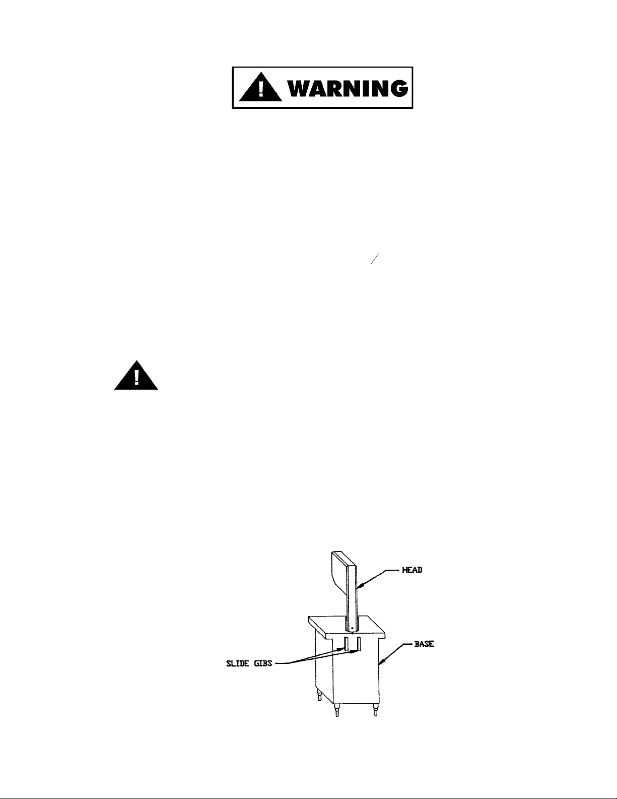
5. The head structure (Part No. 16005) comes detached from the base. Slip the head into the slide gibs (Part No.
260) located on the back of the base structure. Make sure the slide gibs are oiled or greased to ensure free verti-
cal movement of the head structure.
3
ALWAYS LEVEL MACHINE BEFORE USING
Page 6

6. Place removable finger lift with saw guard assembly (Part No. A211) on the saw guide bar (Part No. 116-22) and
fasten in place with finger lift fastener knob (Part No. 211A-291Q).
7. Placing blade on cutter: Hang upper wheel assembly (Part No. A16003U335-6) on the hinge bracket (Part No.
71-1). lift the nylon filler (Part No. 177). Hang blade on the upper wheel and hold with right hand. With left hand
force the back of the blade between the front blade cleaners (Part No. 131), located below the nylon filler. Lower
the nylon filler and insert the back of the blade in the upper saw guide (Part No. 602B). The blade has already
dropped over the lower wheel. With right hand force the back of the blade between the rear blade cleaners (Part
No. 131). The blade is now ready to be tightened. Press down on the ratchet arm (Part No. 10-1) located at the
rear of the base structure. Turn the upper wheel slowly by hand to ensure proper tracking of the saw blade on
the wheels. Tighten to proper tension. When the tension gauge (Part No. 16197), located at the bottom rear of
the head becomes tight laterally the blade is at proper tension.
8. The side platter bracket (Part No. S12214B) is packed loose in the machine and must be installed on the left side
of the base structure with the supplied hardware and checked for proper adjustment. Stationary platter must be
flat.
9. The stationary platter (Part No. A16163-1) is placed on top of the base structure and held in place by two
push-pull hold down catches (Part No. 16212), located on the base structure.
10. The sliding meat carriage assembly (Part No. A16155) is installed by turning the movable stop assembly (Part No.
A16200) clockwise. After the carriage assembly is in the channel for operation, turn the movable stop
counterclockwise to lock.
11. Post SAFETY TIPS wall chart within easy view of operator. Keep Manual available to operator.
12. Machine MUST be properly grounded. Use qualified electrician to install according to building codes.
WIRING MOTOR
(1) Interchange of current is made in motor outlet box. Leads are properly marked. Changing instructions are
on motor plate or motor outlet box.
(2) All cutters are wired 220 volts unless otherwise specified. Be sure motor specifications (voltage, cycle, phase)
match power supply line. Be sure line voltage is up to specification.
(3) Connect leads to machine in a manner that will be approved by local electrical inspectors.
(4) We recommend no less than No. 12 wire. If the leads are too light, machine may not have sufficient cutting
power and/or speed.
(5) The drive belt is packed loose in machine to prevent deformation, and must be installed on pulleys at time of
wiring motor.
(6) The BIRO Manufacturing Company is not responsible for permanent wiring, connection or installation.
4
NOTE TO OWNER AND ELECTRICIAN: IF THIS MACHINE IS NOT CORD
AND PLUG CONNECTED TO THE ELECTRICAL SUPPLY SOURCE, THEN IT
SHOULD BE EQUIPPED WITH, OR CONNECTED TO, A LOCKABLE,
MANUALLY OPERATED DISCONNECT SWITCH (OSHA 1010.147).
SHARP SAW BLADE. HANDLE WITH EXTREME CAUTION
KEEP HANDS CLEAR OF SHARP MOVING BAND TYPE SAW BLADE
Page 7
13. Make sure saw guide bar with saw guard is in its lowest position. Close head and base doors.
14. Push start button and check for proper phasing of motor. Blade should be traveling down through saw guide.
15. Watch for proper tracking of blade. Back of blade should be centered in hole in saw guide in stationary bar (Part
No. 119A). Push stop button to stop machine.
16. Check placement of all warning labels, wall chart and Manual. Machine is ready for trained operators to process
product.
17. Contact your local Distributor or BIRO directly if you have any questions or problems with the installation or operation of this machine.
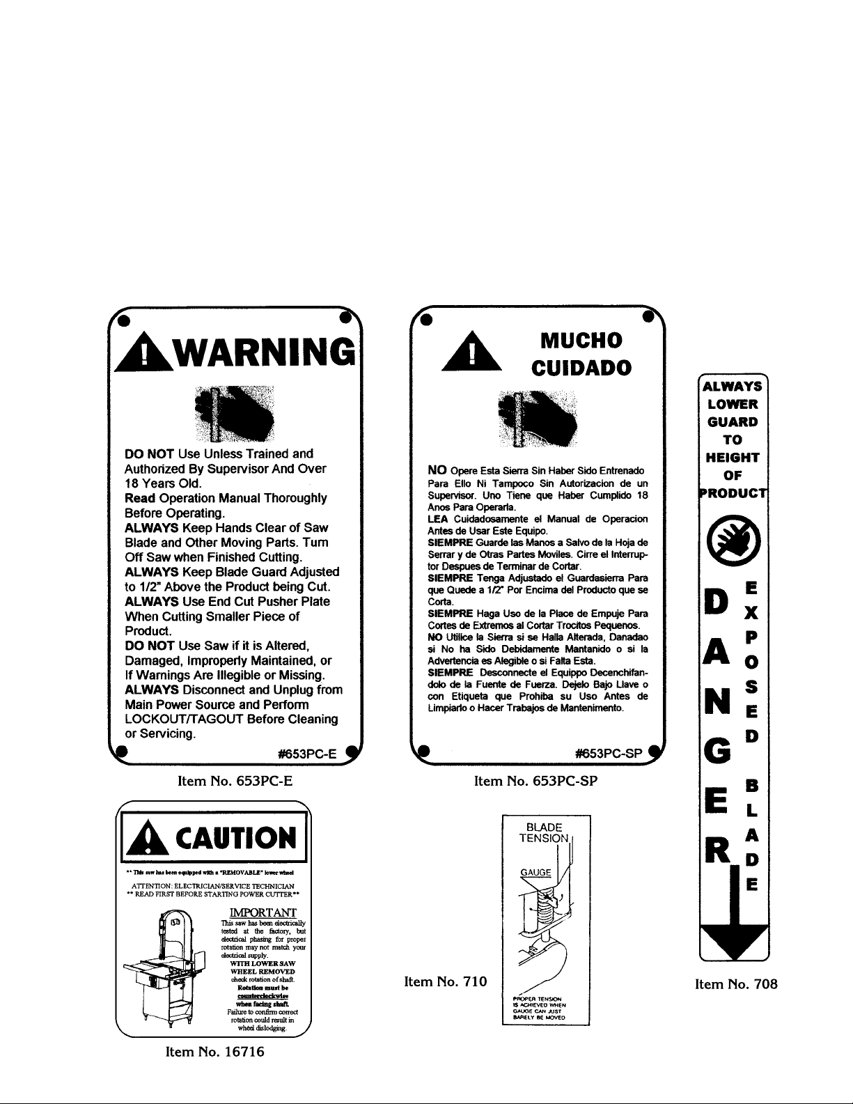
WARNING LABELS
FOR BIRO POWER MEAT CUTTERS
SEE PAGE 34 AND 35 FOR LOCATIONS ON MACHINE
5
Page 8
OPERATION
SHARP MOVING BAND TYPE SAW BLADE
TO AVOID SERIOUS PERSONAL INJURY
ONLY Properly Trained Personnel Should Use This Equipment.
ALWAYS Keep Hands Clear of Band Type Saw Blade and Other Moving Parts.
NEVER Operate with Saw Guard on Saw Guide Bar in the Raised Position or the Saw Guard
Removed from the Saw Guide Bar.
ALWAYS Adjust the Saw Guide Bar with Saw Guard to Within
1
2
" of Product to be Cut.
ALWAYS Use Safety End Cut Pusher Plate for Smaller Products or The Last Cuts of Product.
DO NOT Wear Gloves While Operating.
DO NOT Tamper With, Bypass, Alter, or Modify this Equipment in Any Way From Its Original
Condition.
ALWAYS Turn Off, Unplug from Power Source and Perform Lockout/Tag Out Procedures Before
Cleaning, Servicing or When Not in Use.
NEVER Leave Unattended While Operating.
NEVER Operate Without All Warnings Attached and Wall Chart Posted.
A. TO PROCESS PRODUCT
1. Before starting power cutter, adjust saw guide bar with saw guard down to within ½² (13 mm) of product to
be cut.
6
Page 9
2. Make sure all doors are closed and locked.
3. Adjust meat gauge plate forward to desired thickness of cut.
4. Push start button and watch blade for proper tracking.
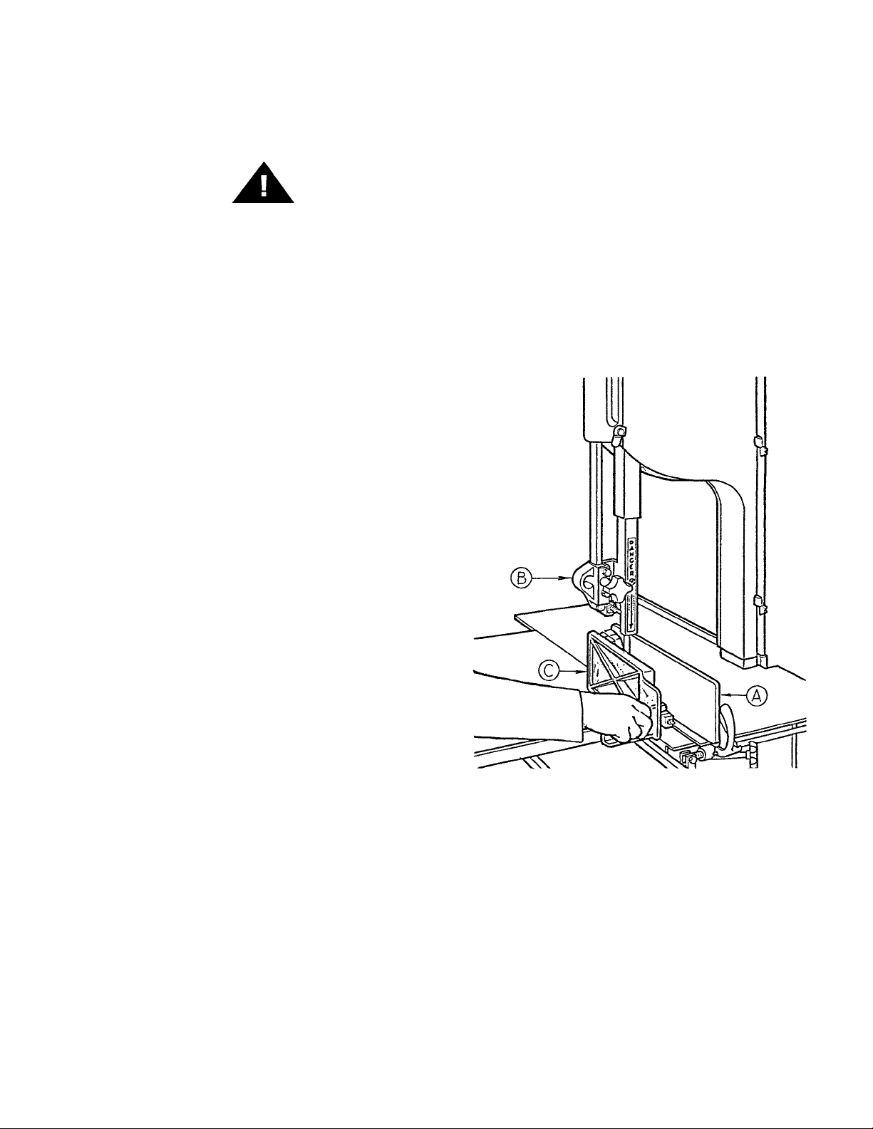
5. Standing in front of the power cutter, place product on the meat carriage. Pay attention to position of your
hands. Keep hands clear of moving band type saw blade. Leaning lightly against the scalloped front edge of
meat carriage, hold the product firmly in right hand with product face flush against meat gauge plate. Move
the meat carriage from right to left at a steady rate until fully past the saw blade. Use left hand to remove and
stack cut product, NEVER REACH IN FRONT OF BAND TYPE SAW BLADE. On the return stroke, pull the
product toward you, away from saw blade.
6. ALWAYS use the Safety End Cut Pusher Plate (Part No. 256P) for smaller products or the last cuts of product.
The pusher plate is supplied as standard on all BIRO power cutters.
7. When finished cutting, push stop button. Perform lockout/tag out procedure.
7
DO NOT WEAR GLOVES WHILE OPERATING
NEVER REACH OR GRAB FOR PRODUCT IN FRONT OF
MOVING BAND TYPE SAW BLADE
Page 10

CLEANING
SHARP MOVING BAND TYPE SAW BLADE
TO AVOID SERIOUS PERSONAL INJURY
ALWAYS Turn Off, Unplug From Power Source and Perform Lockout/Tagout Procedure to This
Machine BEFORE Cleaning or Servicing.
ONLY Use Recommended Cleaning Equipment, Materials and Procedures.
NEVER Spray Water or Other Liquid Substances Directly at Motor, Power Switch or any Other
Electrical Components.
ALWAYS Thoroughly Clean Equipment at Least Daily.
CLEANING THE BIRO POWER CUTTER:
Disconnect electrical power to the machine before cleaning. Parts to be removed have been made accessible and can
be removed without tools. Notice in the drawing below that all parts are numbered. Each part should be removed for
cleaning in the numbered sequence shown. To ensure cleaner cuts, keep the cleaning system in good condition.
Parts on the cleaning system which should be checked weekly, and changed as required are as follows: Wheel
Cleaners (Part No. 179), Saw Cleaners (Part No. 131), Saw Guide in Stationary Bar (Part No. 119A), Upper Saw Guide
(Part No. 602B), Lower Blade Back-Up Guide (Part No. 605) and Nylon Filler (Part No. 177).
8
Page 11
MAINTENANCE
SHARP MOVING BAND TYPE SAW BLADE
TO AVOID SERIOUS PERSONAL INJURY
ALWAYS Turn Off, Unplug From Power Source and Perform Lockout/Tag Out Procedure to This
Machine BEFORE Cleaning or Servicing.
NEVER Touch This Machine Without Training and Authorization By Your Supervisor.
ALWAYS Keep Hands Clear of Band Type Saw Blade and Other Moving Parts.
NEVER Bypass, Alter, or Modify This Equipment in Any Way From Its Original Condition.
PROMPTLY REPLACE Any Worn or Illegible Warning Labels.
USE ONLY GENUINE BIRO Parts and Accessories Properly Installed.
A. GENERAL
1. Machine should be generally inspected every time it is cleaned (at least daily) to ensure that it is in good condition
and has not been damaged or tampered with.
a. SAW WHEELS: Clean outer diameter grooves daily. Check for cracks, gouges or wear on the flange and
grooves.
b. WHEEL CLEANER ASSEMBLIES: Check condition of fiber cleaner, change every four (4) weeks.
c. REMOVABLE FINGER LIFT ASSEMBLY: Check condition of saw guard, make sure mounting bolts are
tight and DANGER EXPOSED BLADE decal is attached and legible. Check condition of upper saw guide
(Part No. 602B), replace every six (6) months. Check adjustment of upper saw guide. Should be ” between
back of blade and saw guide carbide.
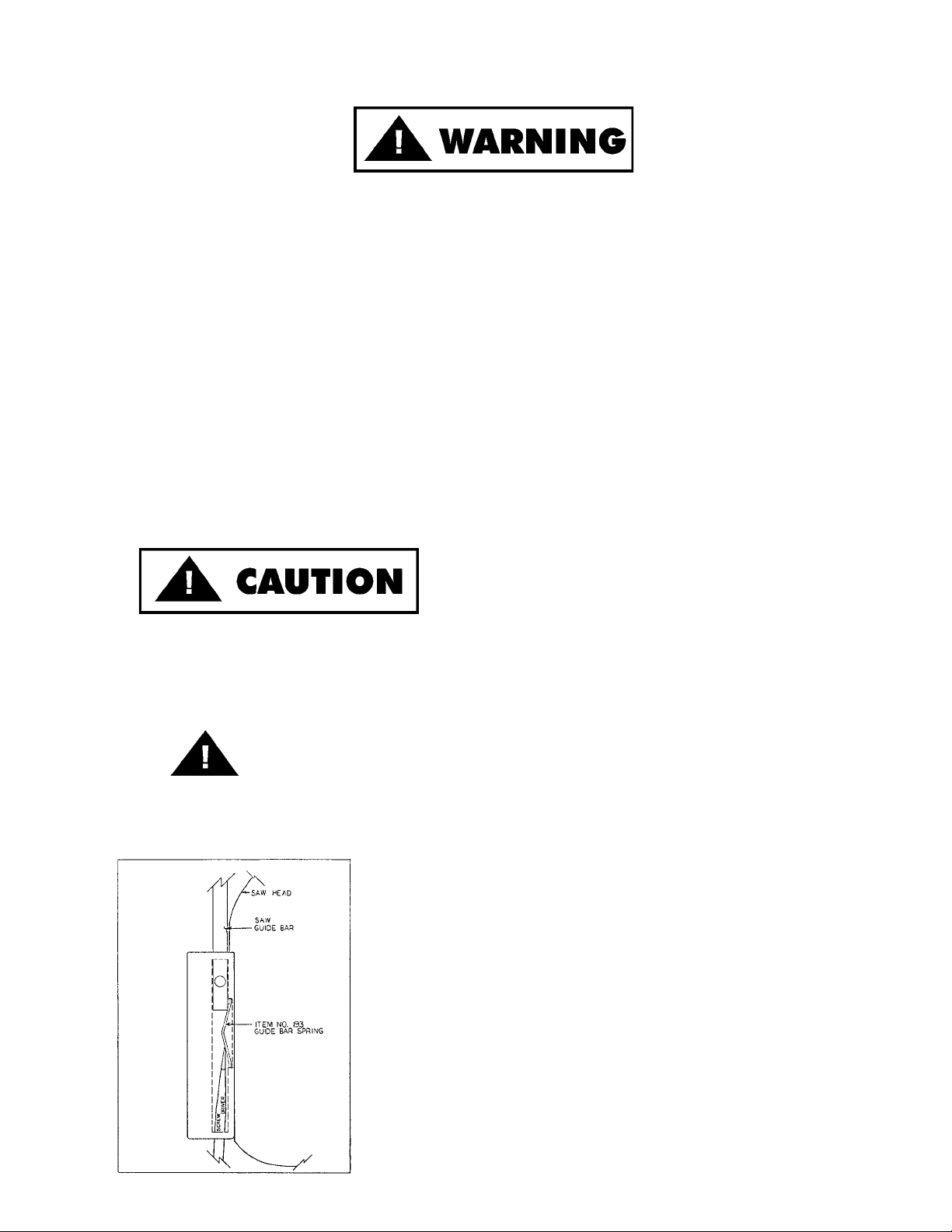
d. SAW GUIDE BAR: Check condition of bar for coating peeling and wear, replace as necessary. Check saw
guide bar spring for proper tension. The spring should hold the bar in any desired position in its travel.
Replace saw guide bar spring (Part No. 193) as necessary using instructions below.
9
DO NOT IMMERSE UPPER WHEEL
ASSEMBLY IN WATER
NEVER USE THIS MACHINE WITHOUT PROPERLY INSTALLED
AND FUNCTIONING SAW GUIDE BAR AND SAW GUARD
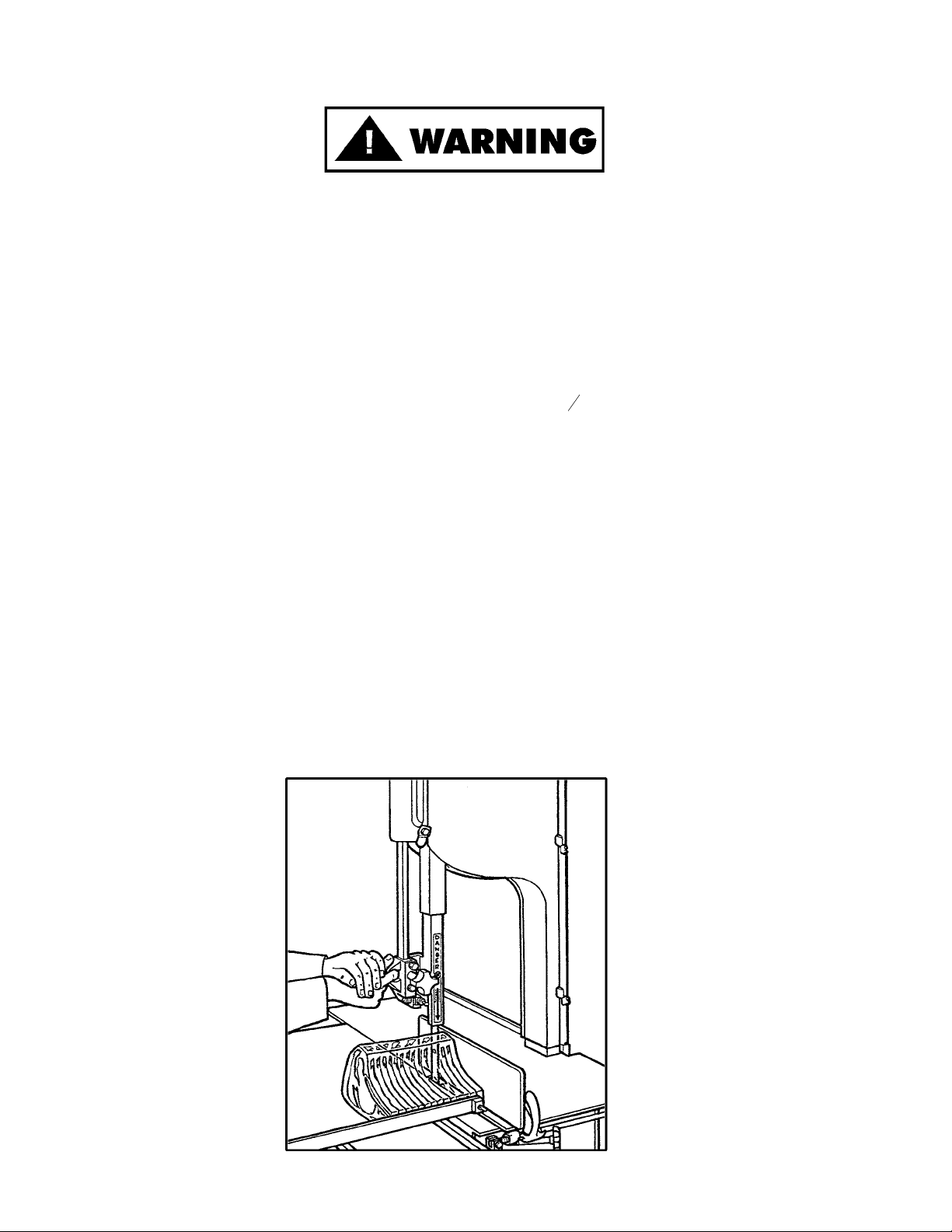
1. Remove the finger lift fastener knob and the fingerlift assembly.
2. Remove the finger lift fastener stud.
3. Push the saw guide bar up and out of the top of the head structure.
4. Remove the saw guide bar spring.
5. Clean and lubricate the babbitt pocket area (the square indented area
that seats the saw guide bar spring).
6. Lower the new saw guide bar spring through the top of the babbitt
pocket area and guide the spring into position with a standard
screwdriver. (NOTE: Drawing)
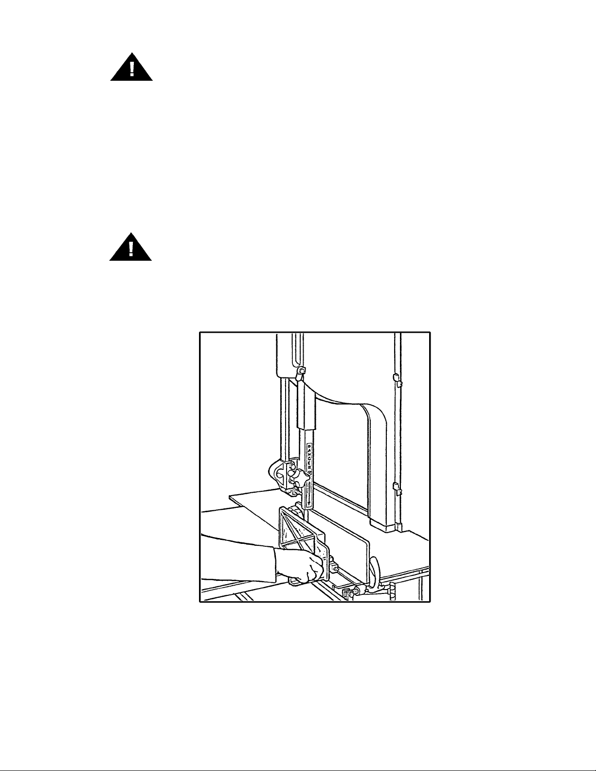
7. While holding the saw guide bar spring in position, re-enter the saw
guide bar from the top compressing the saw guide bar spring slightly
until the saw guide bar slides past the spring.
8. Replace the finger lift fastener stud, the fingerlift assembly and the
finger lift fastener knob.
9. Test by making several adjustments.
Page 12
e. STATIONARY BAR ASSEMBLY: Check condition of nylon filler (Part No. 177), change every four (4) weeks.
Check condition of saw guide (Part No. 119A), check tracking of blade through guide, back of blade should
be centered in hole, replace every six (6) months. Check condition of lower blade back-up guide (Part No.
605). Check adjustment of back-up guide, should have
1
32
² gap between back of blade and saw guide
carbide. Replace every six (6) months.
f. SAW CLEANERS: Check condition of blade cleaners, replace every four (4) weeks.
g. RATCHET ASSEMBLY: Check for smooth operation through full range of travel. Check condition of trigger
spring, replace as necessary.
h. SLIDE GIBS: Check that head structure moves freely up and down. Check for side to side and front to rear
tolerance, adjust as required. Grease every four (4) weeks.
i. MEAT GAUGE ASSEMBLY: Check free movement of meat gauge plate on gear rack. Gear rack to be kept
lubricated at all times with light food grade oil. Check operation of release handle. Check that worm gear
engages properly with gear rack. Check tension of release handle spring, replace as necessary.
j. MEAT CARRIAGE ASSEMBLY: Check for free movement through full range of travel. Check for side to
side tolerance, adjust as necessary. Check condition and grease bearings, replace as necessary. Check
condition of thumb guard, replace as necessary.
k. SAFETY ITEMS: Safety end cut pusher plate is with machine and accessible. All warning labels are present,
properly affixed and legible. Model and Serial Number plate properly affixed and legible. Wall poster within
operators view from machine. Manual
accessible to operator.
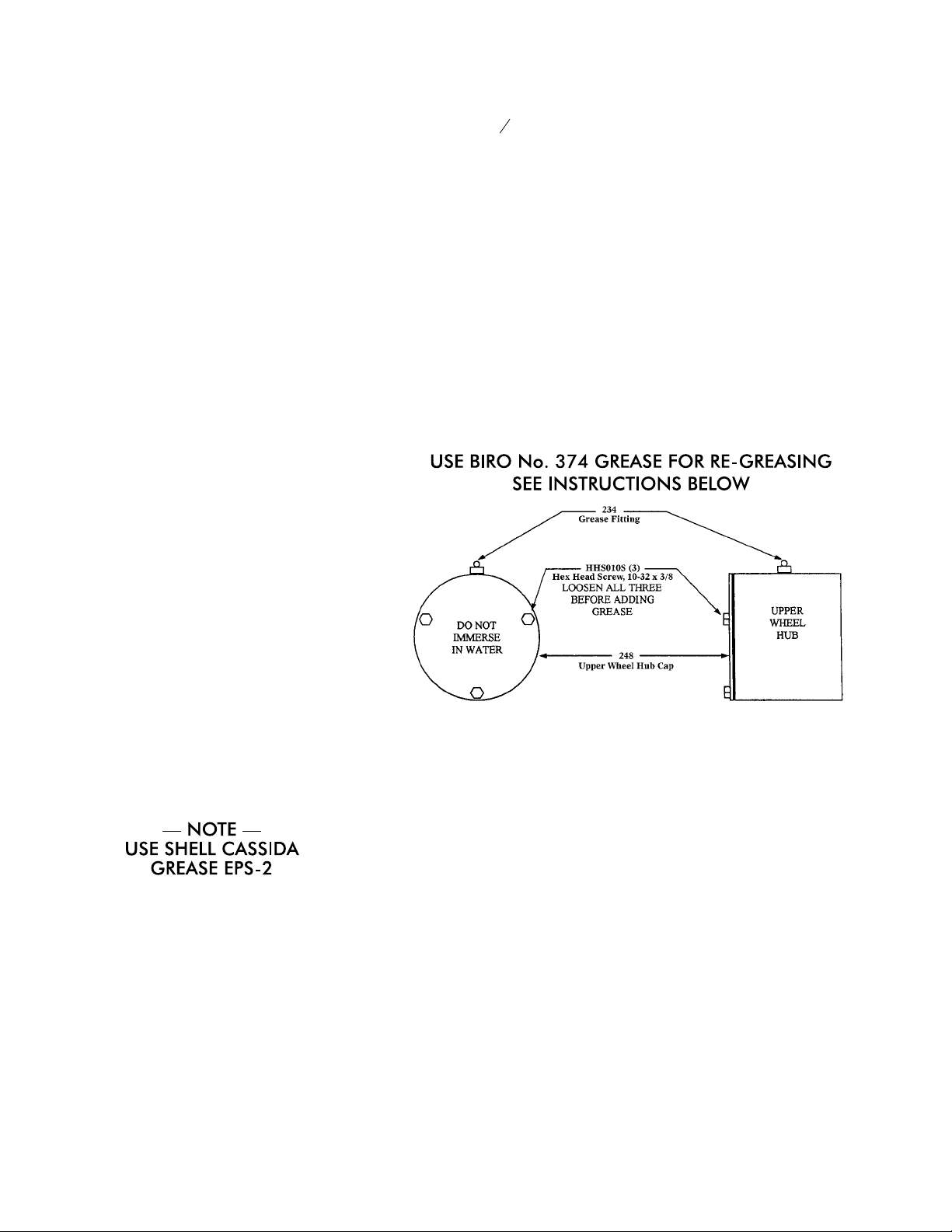
B. LUBRICATION
1. UPPER WHEEL BEARINGS: Grease ev-
ery four (4) months. Change grease every
twelve (12) months. (See instructions at
right.)
2. LOWER BEARING HOUSING: Grease
every four (4) months. Change grease
every twelve (12) months.
3. SLIDE GIBS: Grease every four (4) weeks.
4. MEAT CARRIAGE BEARINGS: Grease
every four (4) weeks.
5. SAW GUIDE BAR: Oil daily with food
machine oil.
6. MEAT GAUGE GEAR RACK: Oil daily
with food machine oil.
7. MOTOR BEARINGS: Bearing grease will lose its lubricating ability over time, not suddenly. The lubricating abil-
ity of a grease (over time) depends primarily on the type of grease, the size of the bearing, the speed at which the
bearing operates and the severity of the operating conditions. Good results can be obtained if the following recommendations are used in your maintenance program.
A high grade ball or roller bearing grease should be used. Recommended grease for standard service conditions
is Polyrex EM (Exxon Mobil).
Equivalent and compatible greases include: Texaco Polystar, Rykon Premium #2, Pennzoil Pen 2 Lube, and
Chevron SRI.
Recommended lubrications intervals is every 9 months with the equivalent of two (2) teaspoons of grease.
10
When lubricating the upper wheel bearing it is important that the three
hex head screws securing the upper wheel hub cap be loosened slightly
before attempting to pump grease into the grease fitting. Loosening the
screws allows for an escape of old broken down grease and air from the
bearing cavity. Failure to loosen the screws before greasing the upper
bearings can cause the upper shaft seal to be dislodged from the upper
wheel allowing grease to escape and moisture to get into the cavity.
When finished greasing the bearings, retighten the three screws. Take
care to also clean off any grease that was forced out of the cavity during
greasing.
Page 13
ITEM NUMBER 671
WALL CHART “BAND SAW SAFETY GUIDELINES”
ATTACH TO WALL IN VICINITY OF MACHINE IN EASY VIEW OF OPERATOR
WARNING
ONLY PROPERLY TRAINED PERSONNEL
SHOULD USE THIS EQUIPMENT
This Saw Contains A Sharp Blade.
To Reduce Risk of Injury:
1. Before Using, Make Sure:
.
Gauge Plate
!
And Other Components
Are Secure.
.
All Warning Labels And Guards Are In Place.
. The Guide Bar
"
Is Adjusted To ½ Inch
Above The Product To Be Cut
2. While Cutting:
.
Keep Hands and Fingers Away From Blade.
.
Keep Product Securely Against Gauge Plate.
.
Use End Cut Pusher
#
When Making
Final Cuts. Item No. 256P.
3. Before Cleaning:
.
Turn Off Power and Unplug.
.
Remove Saw Blade.
.
Use Extra Care When Handling The Saw Blade.
USE YOUR
MEAT SAW SAFELY!
SEE PARTS AND SERVICE MANUAL SUPPLIED WITH MACHINE FOR ADDITIONAL SAFETY INFORMATION.
11
Page 14
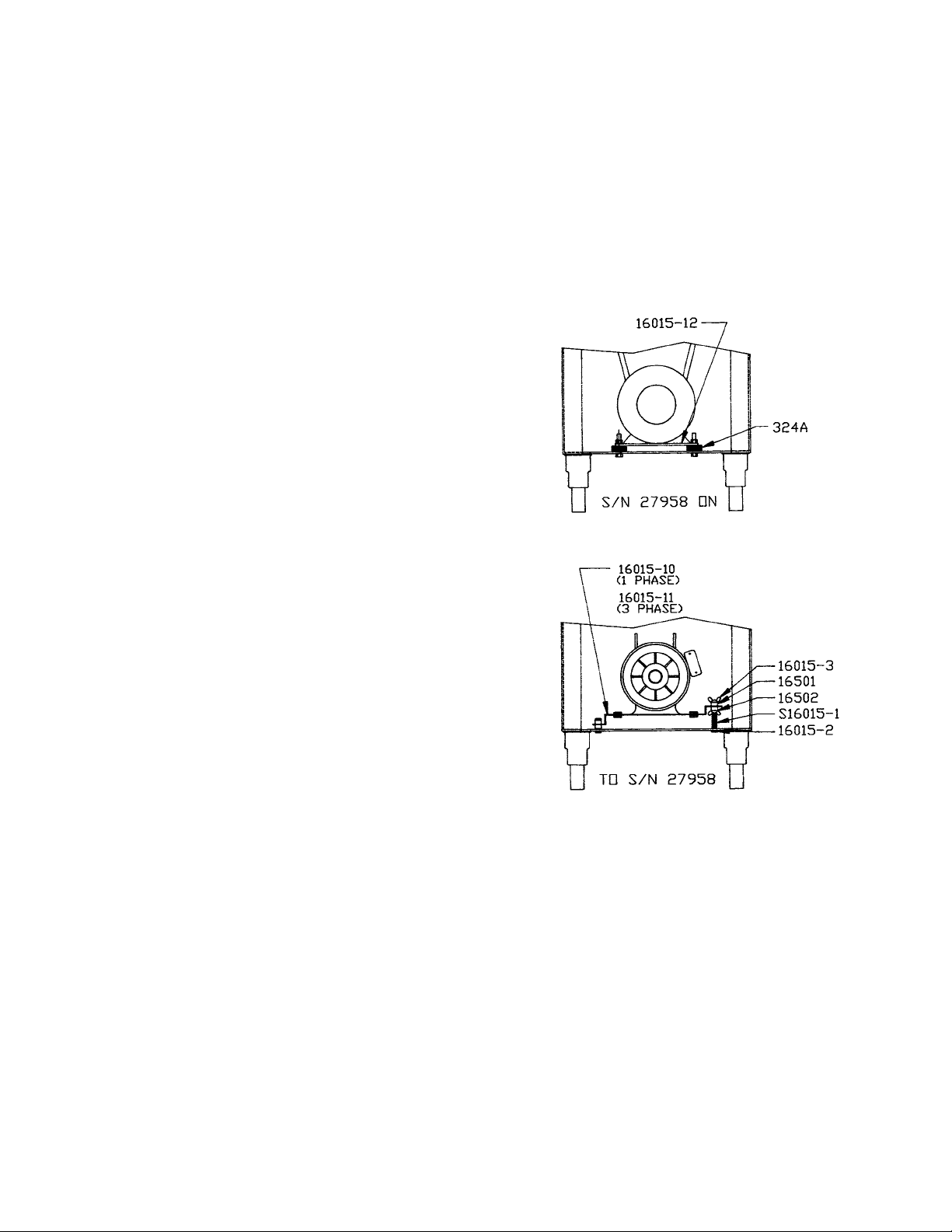
C. MOTOR ADJUSTMENT
Starting with Serial Number 27958 three (3) phase Model 3334’s will no longer be equipped with an adjustable
motor base plate, Part No. 16015-10 and 16015-11. The motor will be bolted to the bottom of the base structure and
V-belt tension adjusted utilizing shims.
This change has evolved as a result of the market demand for higher blade speeds. The revised mounting proce
-
dure will insure a more rigid motor installation creating positive belt alignment and minimizing machine vibration.
The base bottom has been redesigned to accept the frame sizes of the current 3 phase motors. Units prior to Serial Number 27958 can be retrofitted by ordering Part No. 16015-12 motor base plate and template (flat), and 36
pieces Part No. 324A motor shims.
ADJUSTMENTS
D. SAW GUIDE BAR AND SAW GUARD
The factory recommends that when service is performed on any BIRO SAW the servicing agency be sure that the
BIRO SAW is equipped with the most current safety features available.
In September 1969 production of the Model 3334 began and is current. The Model 3334 was first equipped with
19” saw guide bar until March 1973 when the length was extended to 23”. In June 1977, the bar was shortened to
22” and is used in current production.
The same saw guard (Part No. 255) on saw guide bar used on the Models 33 and 34 was carried over to the Model
3334 and used in production until June 1975.
Part No. 663 Saw Guard on saw guide bar replaced Part No. 255 in June 1976 starting with Serial No. 12242. At
the same time, the Part No. 661 Guard on head Door introduced in 1974 was replaced by Part No. 661-1 Guard on
Head Door. Both Part No. 663 and 661-1 are current production today.
The factory recommends that all Model 3334’s prior to Serial No. 12242 be updated by installing the current SAW
GUIDE BAR ASSEMBLY (Part No. A116-22) and SAW GUARD ON HEAD DOOR (Part No. 661-1).
12
1. For tightening motor V-belt on rigid base plate, remove appropriate quantity of shims (Part No. 324A) under the motor
until the desired total flex of the V-belt is approximately ½”.
1. For tightening motor V-belt on old style floating adjustable
motor mounting plates (Part No. 16015-10 and 16015-11),
loosen the upper wing nuts (Part No. 16015-3). Then
loosen the bottom wing nuts (Part No. 16015-3) which are
located under the mounting plate. This enables the motor
mounting plate to drop to the desired belt tension.
Re-tighten the upper wing nuts evenly so that the motor
stays horizontal. Do not tighten belt to extremes. This will
cause undue pressure on and premature failure of the motor bearings.
Page 15

13
Page 16

14
Page 17

15
A16163-5
A16163-4
A16163-4E-COS
Page 18

16
Item No. Description
A16005 Head & door assembly
A16006 Head door assembly
A16014L Head door hinge assembly, lower
16014L-1 Head door hinge – short pin
A16014U Head door hinge assembly, upper
A16112 Head door latch assembly
A661-1 Saw guard on head door assembly
A71-1 Upper wheel hinge bracket assembly
HHS025S Hex head screw,
1
4
-20
´
1
2
SS
HHS035S Hex head screw,
1
4
-20
´
5
8
SS
HHS050S Hex head screw,
5
16
-18
´
5
8
SS
HHS060S Hex head screw,
5
16
-18´1SS
HN15S Hex nut,
1
4
-20 SS
LW10S Lock washer,
1
4
SS
LW15S Lock washer,
5
16
SS
Item No. Description
SSS15 Set screw
5
16
-18
´
5
16
cup point
112-212 Waved washer
116KS Saw guide bar lock knob – aluminum head
14GP Head door hinge pin, 1
1
2
"
14GP-1 Head door hinge pin, 1
1
4
"
16005 Head, aluminum
16006 Head door, aluminum
16014L Head door hinge, lower half *NSS
16014U Head door hinge, upper half *NSS
16112 Head door latch
193 Guide bar spring
194 Locking knob pad
661-1 Saw guard to head door
71-1 Upper wheel hinge bracket
Item No. Description
A16112 Head door latch assembly
AS16005 Head & door assembly SS
AS16006 Head door assembly SS
A71-1 Upper wheel hinge bracket
assembly
HHS050S Hex head screw,
5
16
-18
´
5
8
SS
HHS060S Hex head screw,
5
16
-18´1SS
LW15S Lock washer,
5
16
SS
SSS15 Set screw
5
16
-18
´
5
16
cup point
S16005C Head SS
S16006 Head door SS
14R Head door hinge, welded
14TP Head door hinge pin, 1
1
2
"
14TP-1 Head door hinge pin, 1
1
4
"
112-212 Waved washer
16112 Head door latch
193 Guide bar spring
194 Locking knob pad
194KS-1 Saw guide bar lock knob –
stainless head
71-1 Upper wheel hinge bracket
14P Head door hinge 11⁄2”
14P-1 Head door hinge 11⁄4”
14P
14P-1
Page 19

17
Item No. Description
A16003U-6 Upper wheel assembly without hinge plate
A16003U335-6 Upper wheel assembly with hinge plate
A16003UDF-6 Upper double flange wheel assembly without hinge plate
A16003UDF335-6 Upper double flange wheel assembly with hinge plate
A247-1 Upper shaft bearing assembly
AS16335X Upper wheel hinge plate assembly
A227 Bearing cup/cone assembly
A295 Wheel cleaner assembly
Item No. Description
HHS005S Hex head screw, 8-32
´
1
2
SS
HHS010S Hex head screw, 10-32
´
3
8
SS
HN05S Hex nut 8-32 SS
HN35S Hex nut
3
8
-16 SS
S16335X Upper wheel hinge plate, SS
S229 Wheel cleaner arm torsion spring, SS
S244 Wheel cleaner arm stud, SS
S253 Upper wheel aligning screw, SS
S295 Wheel cleaner arm, SS
S325 Wheel cleaner washer, SS
16003U-6 Upper wheel, 16", 6 spoke
179 Wheel cleaner
230DL Upper shaft seal, double lip
234 Grease fitting, upper wheel
237 Upper shaft castellated lock nut
238 Upper shaft castellated lock nut washer
247 Upper shaft
248 Upper wheel hub cap
252X Shaft lock nut
513 Upper wheel hub gasket
530 Retaining ring (2 req.)
Item No. Description
A16360 Lower bearing housing assembly without
wheel
A16361 Lower shaft bearing assembly
A363 Bearing cup/cone assembly
HN25S Hex nut,
3
8
-16 SS
LW25S Lock washer,
3
8
SS
SSS20 Set screw,
3
8
-16
´
3
8
cup point
S360CB-1 Carriage bolt,
3
8
-16 1
1
4
SS
12251AL Upper V-belt pulley 9´1AL
16003-6 Lower wheel 16", 6 spoke
16003DF-6 Lower double flange wheel 16², 6-spoke
16251AL Upper v-belt pulley, 11.4´1AL
16303 Lower shaft nut
16360 Lower bearing housing
16361 Lower shaft
231DL Lower shaft seal, double lip
277 Lower shaft key
300 Lower shaft Woodruff key
360A1 Grease fitting
360B-1 Set screw,
1
2
-13
´
1
2
flat point
362 Lower bearing housing adj. cap
Page 20

18
Item No. Description
A19-1 Ratchet assembly
FW07S Flat washer,
3
8
SS
HHS040S Hex head screw,
1
4
-20´¾SS
HN15S Hex nut,
1
4
-20 SS
HN35S Hex nut,
3
8
-16 SS
LW10S Lock washer, SS
S11 Ratchet trigger SS
S189 Ratchet arm stud SS
S19 Ratchet base SS
10-1 Ratchet arm
19CB Carriage bolt
1
4
-20
´
3
4
SS
S240 Ratchet trigger spring
Item No. Description
A16278 Meat gauge plate assembly less release
assembly
A262 Meat gauge release assembly
AS16273-S275 Meat gauge assembly
AS16275 Meat gauge plate assembly with release
assembly
FW10S Flat washer,
5
16
,SS
HHS035S Hex head screw ¼-20
´
5
8
HHS049NL Hex head screw,
5
16
-18
´
1
2
, nylon
HHS060S Hex head screw,
5
16
-18´1, SS
HN20S Hex nut,
5
16
-18, SS
LW10S Lock washer,
1
4
,SS
LW15S Lock washer,
5
16
,SS
S16272 Meat gauge gear rack, stainless
S16273 Meat gauge bracket, SS
S16275 Meat gauge plate, SS
Item No. Description
S235 Taper pin, 4
´
3
4
,SS
S262 Meat gauge release handle, SS
16278 Meat gauge arm
264G Meat gauge hand wheel groove pin
264-1 Meat gauge hand wheel
264-1S Hand wheel shim
S265 Meat gauge release spring
267 Meat gauge release cotter key
270 Meat gauge release pin
271AL Meat gauge worm gear, aluminum
272-7-1 Lock knob,
5
16
-18, 3 point
272-8 Cap nut,
5
16
-18 SS
272-9 Hex bolt,
5
16
-18´2SS
272-12 Brass ball
272-13 Hex head screw,
5
16
-18´1
1
4
,SS
272-14 Castellated nut,
5
16
-18, SS
Page 21

19
Item No. Description
A16Z Guide bracket saw cleaner assembly
A295 Wheel cleaner assembly
AS16290 Cleaning unit total assembly
FW05S Flat washer,
1
4
SS
HHS003S Trimmed hex head screw 8-32
´
1
4
,SS
HHS005S Hex head screw, 8-32
´
1
2
SS
HHS035S Hex head screw,
1
4
-20
´
5
8
SS
HHS040S Hex head screw,
1
4
-20
´
3
4
SS
HHS070S Hex head screw,
3
8
-16´1SS
HN05S Hex nut, 8-32 SS
HN10S Hex nut, 10-32 SS
LW10S Lock washer,
1
4
SS
LW25S Lock washer,
3
8
SS
RHS20S Round head screw, 10-32´1
1
8
SS
S16290 Cleaning unit stamping, SS
S229 Wheel cleaner arm torsion spring SS
S235 Taper pin 4
´
3
4
,SS
S244 Wheel cleaner arm stud SS
S295 Wheel cleaner arm SS
S325 Wheel cleaner washer SS
131 Saw cleaner SS
16Z Lower guide bracket saw cleaner holder
179 Wheel cleaner
211A-291Q Fastener knob, 4 point
228-2 Lower guide washer
605 Saw guide lower blade back-up
Item No. Description
A116-22AL Saw guide bar assembly 22" – aluminum
A116-22KSS Sw guide bar assem. with lock knob 22" – stainless
A116-22SS Saw guide bar assembly 22" – stainless
A116-22-COS Saw guide bar assembly – 22" SS special
A211-AL Finger lift assembly, removable – aluminum
A211-SS Finger lift assembly, removable – stainless
A211-COS Finger lift assembly – removable SS special
A602 Saw guide assembly, upper
FW05S Flat washer,
1
4
SS
HHS015S Hex head screw, 10-32
´
7
8
SS
HHS020S Hex head screw,
1
4
-20
´
3
8
SS
HHS083S Hex head screw
3
8
-16´1¾ SS
HN10S Hex nut, 10-32 SS
LH663 Saw guard for true left head
LW05S Lock washer, #10 SS
LW10S Lock washer,
1
4
SS
RHS10S Round head screw, 10-32
´
3
4
SS
RHS30S Round head screw,
1
4
-20
´
7
8
SS
S200B1 Stop stud on guide bar
116KS Saw guide bar lock knob – aluminum head
S116-22 Saw guide bar, 22"
S116-22-COS Saw guide bar – 22" special
16662 Saw guard for SS head
16662-COS Saw guard – special
17211-22 Finger lift, shim, .022
17211-35 Finger lift, shim .035
193 Saw guide bar spring
194 Locking Knob pad
194KS-1 Saw guide bar lock knob – stainless head
211 Finger lift bracket
211A-291Q Fastener knob, 4 point
601 Upper saw guide bracket
602B Upper saw guide with carbide
602AFSC Upper saw guide, narrow, fish
663 Saw guard for aluminum head
708 Decal “DANGER EXPOSED BLADE”
SSAAWW GGUUIIDDEE BBAAR
AASSSSEEMMBBLLY
Y
R
194KS-1
OR
194KS
Item No. Description
AA111166--2222AALL
AA111166--2222SSSS
AA111166--2222--CCOOSS
AASS111166--2222--CCOOSS
AASS111166--2222
AASS111166--2222SSSS
Saw guide steel bar assem. - 22” Al. head
Saw guide steel bar assem. - SS head
Saw guide steel bar assem. - 22” Costco Al. head
Saw guide SS bar assem. - Costco SS head
Saw guide SS bar assem. - Al. head w/lock knob
Saw guide SS bar assem. - SS head w/lock knob
S116-22
S116-22-COS
A116-22AL
A116-22SS
A116-22-COS
AS116-22-COS
AS116-22
AS116-22SS
SAW GUIDE BAR
ASSEMBLY
Page 22

20
Item No. Description
A415D Stationary bar assembly
HN15S Hex nut
1
4
-20 SS
LW10S Lock washer,
1
4
SS
S268 Stationary bar headless screw
119A Saw guide in stationary bar
177 Nylon filler
415D Stationary bar
Item No. Description
A130 Saw cleaner assembly
A16132 Steel cleaner assembly, rear
HHS003S Trimmed hex head screw 8-32
´
1
4
,SS
HHS025S Hex head screw,
1
4
-20
´
1
2
SS
LW10S Lock washer,
1
4
SS
130 Saw cleaner bracket rear
131 Saw cleaner SS
16132 Saw cleaner bracket holder, rear
175-2-S Thumb screw,
1
4
-20
´
1
2
16133 Fastener knob – 4 point
Item No. Description
A16196 Tension spring assembly
HHS040S Hex head screw,
1
4
-20
´
3
4
SS
LW10S Lock washer,
1
4
SS
111AL Tension spring pin, ALI
S118 Tension spring plate
16197 Tension spring gauge
196 Saw tension spring
198 Cap, for tension pin
Item No. Description
AS415D Stationary bar assembly SS
HHS025S Hex head screw
1
4
-20´½SS
LW10S Lock washer,
1
4
SS
S268 Stationary bar headless screw
S415D Stationary bar SS
119A Saw guide in stationary bar
177 Nylon filler
S119A
S119A Saw guide in stationary bar - stainless
Page 23

STANDARD 3334 MEAT CARRIAGE & CHANNEL
21
Item No. Description
A16155 Meat carriage assembly complete
A175S Thumb guard assembly
FW05S Flat washer,
1
4
SS
AN15S Acorn nut,
1
4
-20 SS
AN20S Acorn nut,
3
8
-16 SS
HN30S Hex nut,
3
8
-16 light jam SS
LW20S Lock washer
3
8
regular SS
S155 Meat carriage top only (NSS)
S155-R Raw meat carriage top only (DNS)
S155-11 Meat carriage stop thumb screw
Item No. Description
16155 Meat carriage top & angle only
16155-2A Meat carriage guide
16155-2B Meat carriage guide spacer,
1
64
TK
16155-2C Meat carriage guide spacer,
1
32
TK
16155-13 Carriage stop angle SS, welded
16155AEZ-1 Meat carriage angle plate only (DNS)
16159 Meat carriage bearing SS
175S Thumb guard,nylon
175-1-S Thumb guard nut SS
175-2-S Thumb screw
1
4
-20
´
1
2
Item No. Description
A16200 Carriage stop assembly, movable
A16220-1 Carriage stop assembly, fixed
AS16120 Channel assembly, 37"
FW08S Flat washer,
3
8
SS
FW15S Flat washer,
1
2
SS
HHS075S Hex head screw,
3
8
-16´1
1
4
SS
HN25S Hex nut,
3
8
-16 SS
LW15S Lock washer,
5
16
SS
LW25S Lock washer,
3
8
SS
Item No. Description
S16120 Channel, 37" SS
S200B1 Carriage stop stud SS
S360CB-1 Carriage bolt,
3
8
-16´1
1
4
SS
16200 Carriage stop, movable
16220-1 Carriage stop, fixed
310 Waved washer
311 Rubber bumper, fixed stop
311-1 Rubber bumper, movable stop
376 Drive screw 10
´
1
2
SS
Page 24

OPTIONAL 3334 EZ FLOW MEAT CARRIAGE & CHANNEL
22
Item No. Description
A16155EZ Meat carriage assembly complete – EZ Flow
A175S Thumb guard assembly
FW05S Flat washer,
1
4
SS
AN15S Acorn nut,
1
4
-20 SS
HN30S Hex nut,
3
8
-16 light jam SS
LW20S Lock washer
3
8
regular SS
S155-11 Meat carriage stop thumb screw
S155-R Raw meat carriage top only (DNS)
S155EZ Meat carriage top only (NSS)
Item No. Description
S155EZ-3 Hex stand-off, EZ Flow carriage
16155EZ Meat carriage top & angle only
16155EZ-1 Meat carriage top only w/weld studs (DNS)
16155-13 Carriage stop angle SS
16155AEZ-1 Meat carriage angle plate
16159 Meat carriage bearing SS
175S Thumb guard,nylon
175-1-S Thumb guard nut SS
175-2-S Thumb screw
1
4
-20
´
1
2
,SS
Item No. Description
A16200 Carriage stop assembly, movable
A16220-1 Carriage stop assembly, fixed
AS16120EZ Channel assembly, 37" – EZ Flow
FW08S Flat washer,
3
8
SS
FW15S Flat washer,
1
2
SS
HHS055S Hex head screw,
5
16
-18´¾SS
HHS075S Hex head screw,
3
8
-16´1
1
4
SS
HN25S Hex nut,
3
8
-16 SS
LW15S Lock washer,
5
16
SS
LW25S Lock washer,
3
8
SS
S16120 Channel, 37" SS
S200B1 Stop stud SS, guide bar &
carriage stop
S360CB-1 Carriage bolt,
3
8
-16´1
1
4
SS
16200 Carriage stop, movable
16220-1 Carriage stop, fixed
18120EZ-B3 Guide bar – EZ Flow
310 Waved washer
311 Rubber bumper, fixed stop
311-1 Rubber bumper, movable stop
376 Drive screw 10
´
1
2
SS
Page 25

STANDARD 3334-4003 EZ FLOW MEAT CARRIAGE & CHANNEL
ALSO OPTIONAL ON ALL OTHER 3334
23
Item No. Description
A175S Thumb guard assembly
A181155EZ Meat carriage assembly, EZ Flow
AN15S Acorn nut,
1
4
-20
FW05S Flat washer,
1
4
HN30S Hex nut,
3
8
-16 light jam
LW20S Lock washer, light
S155-11 Carriage stop thumb screw
S155EZ-1 Weld stud – NSS
S155EZ-2 Weld stud – NSS
Item No. Description
S181155AEZ Carriage bearing angle plate
S18155EZ-1 Carriage top w/weld studs
S18155EZ Carriage top without weld studs
S18155EZ-R Raw meat carriage top only (DNS)
S155EZ-3 Hex stand-off
16155-13 Carriage top angle SS
16159 Carriage bearing
175S Thumb guard
175-1-S Thumb guard nut
175-2-S Thumb screw
1
4
-20
´
1
2
Item No. Description
A16200 Carriage stop assembly,
movable
A16220-1 Carriage stop assembly, fixed
AS1120EZ Channel assembly, EZ Flow
FW08S Flat washer,
3
8
FW15S Flat washer,
1
2
HHS055S Hex head screw,
5
16
-18
´
3
4
HHS075S Hex head screw,
3
8
-16´1
1
4
HN25S Hex nut,
3
8
-16
LW15S Lock washer,
5
16
LW25S Lock washer,
3
8
S1120EZ Channel, EZ Flow
16200 Carriage stop, movable
16220-1 Carriage stop, fixed
18120EZ-B3 Carriage guide bar, EZ Flow
310 Waved washer
311 Rubber bumper, fixed stop
311-1 Rubber bumper, movable stop
376 Drive screw 10´½SS
S200B1 Stop stud, SS
S360CB-1 Carriage bolt,
3
8
-16´1
1
4
NOT SHOWN
S1007 Channel bracket, SS
Page 26

24
USED WITH
Motor Model
Mfg. No. Specifications
Doerr XR72927 1
1
2
HP, 220/440-50/60-3 open
Doerr R72929 2HP, 220/440-50/60-3 open
U.S. Motor G54313 2HP, 220/440-50/60-3 open
Doerr 73020 2HP, 550-60-3 open
U.S. Motor G57016 2HP, 550-60-3 open
USED WITH
Motor Model
Mfg. No. Specifications
Doerr 73032 1
1
2
HP, 115/230-50-1 open
U.S. Motor G57347 1
1
2
HP, 115/230-50-1 open
Doerr 72933 1
1
2
HP, 115/230-60-1 open
Baldor L3605 2HP, 115/230-60-1 TE
Baldor L3605-50 2HP, 115/230-50-1 TE
Baldor L1322T 2HP, 115/230-60-1 open
Doerr 67385 2HP, 208/220/440-50/60-3 TE
Baldor M3558T-5 2HP, 550-60-3 TE
Baldor M3558T-50 2HP, 220/380/415-50-3 TE
Baldor M3558T-8 2HP, 200-60-3 TE
Doerr 72540 3HP, 220/440-50/60-3 TE
Doerr 75425 3HP, 220/440-50/60-3 TE
U.S. Motor G57011 3HP, 220/440-50/60-3 TE
Baldor M3611 3HP, 220/440-50/60-3 TE
Baldor M3611T-50 3HP, 220/380/440-50-3 TE
Baldor M3611T-8 3HP, 200-60-3 TE
Doerr 73031 5HP, 220/440-50/60-3 TE
Doerr A907 5HP, 220/440-50/60-3 TE
Item No. Description
A16547 Lower bearing housing assembly without
wheel
A363 Lower bearing cup/cone assembly
HN25 Hex nut
3
8
-16, carbon-plated
LW25S Lock washer,
3
8
heavy
S360CB-1 Carriage bolt,
3
8
-16´1
1
4
SSS05S Set screw, 10-24
´
3
8
12251AL-
7
8
DBL Pulley, 9
´
7
8
double V
14544 Grease seal
14545 Retaining ring, internal
14548 Grease seal
14549 Bearing adj. cap
Item No. Description
14740 Retaining ring – external
14746 T-handle lock, removable lower wheel
16251-11´78AL Pulley, 11.4
´
7
8
AL
16251-90X78AL Pulley, 9
´
7
8
, al.
16517 Inner race spacer
16543 Lower shaft, remov. wheel
16547 Lower bearing housing
16560 Lower wheel, 16", 6 spoke removable
16560DF Lower wheel, 16", 6 spoke removable – double flange
280 Lower shaft motor key
360A1 Grease fitting – angled
360B-1 Set screw, ½-13 SS
The Model 3334 Lower Removable Wheel has been revised to include a keyway in the
bore. Also an anti-rotation pin is now pressed into the lower shaft to prevent any inadvertent "spinning" of the wheel on the shaft.
NOTE – If the saw in which a new shaft is to be in
stalled has a groove (keyway) in the bore of the lower
wheel, press the taper pin (provided "loose") into the
hole in the side of the shaft (see sketch).
If there is no groove (keyway) in the bore of the lower wheel, discard the taper pin and
use the shaft without the pin.
Page 27

LOWER REMOVABLE WHEEL
INSTALLATION AND REMOVAL INSTRUCTIONS
FOR MODEL 3334SS
ALWAYS Turn Off, Unplug From Power Source and Perform Lockout/Tagout Procedure to the
Machine BEFORE Cleaning or Servicing.
Follow disassembly procedures in the Cleaning Section of the Operating and Service Manual.
Removal of the Lower Wheel will be the last procedure.
REMOVAL
Loosen the Item No. 14746 T-Handle Lock, DO NOT REMOVE COMPLETELY FROM SHAFT.
25
Using thumbs for leverage, pull wheel toward
you with an even-smooth motion. Wheel is
mounted in slip fit fashion on a tapered shaft.
When the wheel is loose, complete removing
T-handle lock and wheel.
INSTALLATION
There is an alignment pin on
the lower shaft. And a mating
alignment groove in the hub of
the lower wheel. Align the two
as the wheel is being installed
on the tapered shaft.
Page 28

A609AAW-16
SWITCH ASSEMBLY
26
Item No. Description
A16226A Green/red switch button assembly
w/springs
A609AAW-16 Switch assembly, 1 & 3 ph less heater coils
H462 Guard for switch toggle
H462A Guard assembly for switch toggle
H462-1 Trim ferrule, SS
HHS010S Hex head screw, 10-32
´
3
8
SS
HHS070S Hex head screw,
3
8
-16´1SS
HN10S Hex nut, 10-32 SS
HN20S Hex nut
5
16
-18 SS heavy
LW15S Lock washer
5
16
SS regular
LW25S Lock washer,
3
8
SS
16296-2 Switch bracket SS
150 Conduit,
1
2
"
224 Conduit connector, 180°
226-28 Washer SS, 1
1
2
´
27
32
241BL Wire, black, 12GA., CSA & UL
241WH Wire, white, 12GA., CSA & UL
259 Anti-short busing ½"
340 Star lock washer
609AAW Manual switch, size 0, 1 & 3 ph
Page 29

WATERTIGHT MAGNETIC SWITCH ASSEMBLIES
(AEG)
INCLUDES MOUNTING BRACKET AND WIRES
27
Item No. Description
A22616AE-506 BAEG/PC-PB/C6, 1
1
2
HP,
208/220/230-50/60-3
A22616AE-514 BAEG/PC-PB/C8, 2HP,
208/220/230-50/60-3
A22616AE-516 BAEG/PC-PB/E4, 1
1
2
HP, 440/460-3
A22616AE-518 BAEG/PC-PB/D6, 1
1
2
HP, 380/415-50-3;
2HP, 380/415-50-3
A22616AE-520 BAEG/PC-PB/A23, 1
1
2
HP, 104/115-50/60-1
A22616AE-522 BAEG/PC-PB/C12, 1
1
2
HP & 3HP,
208/220/230-50/60-1
A22616AE-524 BAEG/PC-PB/A32, 2HP, 115-60-1
Item No. Description
A22616AE-526 BAEG/PC-PB/C17, 2HP, 230-60-1
A22616AE-530 BAEG/PC-PB/F2.8, 2HP, 550-60-3
A22616AE-534 BAEG/PC-PB/E6, 3HP, 440/460-60-3
A22616AE-536 BAEG/PC-PB/D8, 3HP, 380/415-50-3
A22616AE-538 BAEG/PC-PB/F4, 3HP, 550-60-3
A22616AE-540 BAEG/PC-PB/C23, 5HP,
208/220/230-50/60-3
A22616AE-543 BAEG/PC-PB/E8, 5HP, 440-60-3
A22616AE-546 BAEG/PC-PB/D12, 5HP, 380/415-50-3
A22616AE-548 BAEG/PC-PB/F8, 5HP, 550-60-3
Item No. Description
A16226A-SG Green/red switch button assembly
H462 Guard for switch toggle
H462A Guard assembly for switch toggle
H462-1 Trim ferrule S.S.
HHS070S Hex head screw,
3
8
-16´1SS
HN05S Hex nut, 8-32 SS
HN20S Hex nut
5
16
-18 S.S.
LW03S Lock washer, #8 SS
LW15S Lock washer
5
16
S.S.
LW25S Lock washer,
3
8
heavy SS
RHS075S Round head screw, 8-32
´
3
4
SS
16296-2 Switch bracket SS
151 Watertight conduit
224-1 Conduit connector, WT, 180°
224-1F Conduit ferrule for watertight connector
224-1N Conduit nut for watertight connector
226AE-ENCL-PB Enclosure with button holes
226AE-0L02H Overload, B17S-H (1.8-2.8)
226AE-0L04I Overload, B17S-I (2.8-4)
226AE-0L06K Overload, B17S-K (4.6)
226AE-0L08L Overload, B17S-L (5.6-8)
226AE-0L12M Overload, B17S-M (8-12)
226AE-0L17N Overload, B17S-N (11-17)
226AE-0L23O Overload, B17S-O (15-23)
226AE-0L32P Overload, B17S-P (22-32)
226AE-A0 Contactor, SP17.10-A0, 110V
226AE-C0 Contactor, SP17.10-C0, 208/220/230V
Item No. Description
226AE-D0 Contactor, SP17.10-D0, 380/415V
226AE-E0 Contactor, SP17.10-E0, 440V
226AE-F0 Contactor, SP17.10-F0, 550V
226AE-506 BAEG/PC-PB/C6
226AE-514 BAEG/PC-PB/C8
226AE-516 BAEG/PC-PB/E4
226AE-518 BAEG/PC-PB/D6
226AE-520 BAEG/PC-PB/A23
226AE-522 BAEG/PC-PB/C12
226AE-524 BAEG/PC-PB/A32
226AE-526 BAEG/PC-PB/C17
226AE-530 BAEG/PC-PB/F.28
226AE-534 BAEG/PC-PB/E6
226AE-536 BAEG/PC-PB/D8
226AE-538 BAEG/PC-PB/F4
226AE-540 BAEG/PC-PB/C23
226AE-543 BAEG/PC-PB/E8
226AE-546 BAEG/PC-PB/D12
226AE-548 BAEG/PC-PB/F8
226-28 Washer, 1
1
2
´
27
32
SS
241BL Wire, black, 12 GA., CSA & UL
241GR Wire, green, 12 GA ., CSA & UL
241RD Wire, red, 12 GA., CSA & UL
241WH Wire, white, 12 GA., CSA & UL
297-1 Wire terminal eyelet for 12 Ga. wire
42MC-Y73 Green start push button assembly
42MC-Y74 Red stop push button assembly
Page 30

28
– 115 Volt with 7 Motor Leads –
Model 3334 Schematic Using 3-Pole Stromberg or AEG W.T. Switch
for 115 Volts, Single Phase, 60 Cycle Baldor Motor with 7 Motor Leads
TO ELIMINATE BREAKING EFFECT OF MOTOR AFTER STOP IS ENGAGED
– 115 Volt with 6 Motor Leads –
Model 3334 Schematic Using 3-Pole Stromberg or AEG W.T. Switch
for 115 Volts, Single Phase, 60 Cycle Baldor Motor with 6 Motor Leads
TO ELIMINATE BREAKING EFFECT OF MOTOR AFTER STOP IS ENGAGED
*To Reverse Rotation
Interchange Leads 5 & 8
*To Reverse Rotation
Interchange Leads 5 & 8
Page 31

29
– 230 Volt with 7 Motor Leads –
Model 3334 Schematic Using 3-Pole Stromberg or AEG W.T. Switch
for 230 Volts, Single Phase, 60 Cycle Baldor Motor with 7 Motor Leads
TO ELIMINATE BREAKING EFFECT OF MOTOR AFTER STOP IS ENGAGED
– 230 Volt with 6 Motor Leads –
Model 3334 Schematic Using 3-Pole Stromberg or AEG W.T. Switch
for 230 Volts, Single Phase, 60 Cycle Baldor Motor with 6 Motor Leads
TO ELIMINATE BREAKING EFFECT OF MOTOR AFTER STOP IS ENGAGED
*To Reverse Rotation
Interchange Leads 5 & 8
*To Reverse Rotation
Interchange Leads 5 & 8
Page 32

30
Page 33

31
Page 34

323334
Page 35

Page 36

Page 37

– 208/220/440 WITH 3 PHASE MOTOR –
Model 3334 Schematic Using 3-Pole Stromberg or AEG W.T. Switch
for 208-220/440 Volts, Three Phase, 60 Cycle US or Baldor Motor
Item No. Description
AN15S Acorn nut,
1
4
-20, SS
FW05S Flat washer,
1
4
,SS
FW07S Flat washer,
3
8
,SS
FW08S Falt washer,
3
8
ID´1OD, SS
FW10S Flat washer,
5
16
,SS
FW15S Flat washer,
1
2
, SS
HHS003S Trimmed hex head screw,
8
32
´
1
4
,SS
HHS005S Hex head screw, 10-32
´
3
8
,SS
HHS010S Hex head screw,
8
32
´
1
2
, SS
HHS015S Hex head screw, 10-32
´
7
8
,SS
HHS020S Hex head screw,
1
4
-20
´
3
8
, SS
HHS025S Hex head screw,
1
4
-20
´
1
2
,SS
HHS035S Hex head screw,
1
4
-20
´
5
8
,SS
HHS040S Hex head screw,
1
4
-20
´
3
4
,SS
HHS049NL Hex head screw,
5
16
-18
´
1
2
, nylon
HHS050S Hex head screw,
5
16
-18
´
5
8
,SS
HHS055S Hex head screw,
5
16
-18
´
3
4
,SS
HHS060S Hex head screw,
5
16
-18´1, SS
HHS070S Hex head screw,
3
8
-16´1, SS
HHS075S Hex head screw,
3
8
-16´1
1
4
,SS
HN05S Hex nut, 8-32, SS
HN10S Hex nut, 10-32, SS
HN15S Hex nut,
1
4
-20, SS
HN20S Hex nut,
5
16
-18, SS
HN25 Hex nut,
3
8
´
16
HN25S Hex nut,
3
8
-16, SS
HN30S Hex nut,
3
8
-16, light jam, SS
HN35S Hex nut,
3
8
-16, SS
LH663 Left hand saw guard
LW05S Lock washer, #10, SS
LW10S Lock washer,
1
4
,SS
LW15S Lock washer,
5
16
,SS
LW20S Lock washer,
3
8
, regular, SS
LW25S Lock washer,
3
8
,SS
M55-G54313-U Motor, 2HP 208/220/440-50/60-3, open
M68-67385-D Motor, 2HP, 208/220/440-50/60-3, TE
M701-G57011-U Motor, 3HP, 208/220/230/440-50/60-3, TE
RHS20S Round head screw, 10-32´1
1
8
,SS
RHS10S Round head screw, 10-32
´
3
4
,SS
Item No. Description
RHS25S Round head screw,
1
4
-20
´
3
4
,SS
RHS30S Round head screw,
1
4
-20
´
7
8
,SS
S1007 Channel bracket, SS (3334-4003 only)
S11 Ratchet trigger
S1120EZ Channel, SS (3334-4003 only)
S12214 Platter bracket starting with S/N 24464*
S155-11 Meat carr stop thumb screw
S155B Meat carriage stop welded
S155EZ-3 Hex standoff, EZ flow carriage
S16005C Head, SS
S16006 Head door, SS
S16007 Channel bracket SS
S16015-1 Motor baseplate adjusting stud, SS
S16120 Channel stainless steel
S16217L Base door left panel SS, see page 23
S16217LTP Base door left tapered panel, SS, see page 23
S16217R Base door right hinged SS
S16239-5 Base, stainless steel
S16273 Meat gauge bracket SS
S16275 Meat gauge plate, SS
S16290 Cleaning unit stamping SS
S16296-8 Switch brkt Kroger 800S2SA4
S16335X Upper wheel hinge plate, SS
S181155AEZ Meat carriage angle, EZ flow (3334-4003 only)
S18155EZ-1 Carriage top w/weld studs (3334-4003 only)
S189 Ratchet arm stud, stainless
S19 Ratchet base, stainless
S200B1 Stopstud gde bar & crg stp SS
S217C Base door hinge pin long SS
S217E Base door hinge pin short SS
S229 Wheel cleaner arm torsion spring, SS
S235 Taper pin, stainless, 4
´
3
4
S239-B30 Base foot welded, SS
S239-B40 Base leg, welded
S239-B41 Hex leg, adjustable
S240 Ratchet trigger spring
S244 Wheel cleaner arm stud SS
S253 Upper wheel aligning screw, SS
S262 Meat gauge release handle
35
Page 38

MODEL 3334 PARTS NUMBERS AND DESCRIPTIONS (Cont.)
31
Item No. Description
S268 Stationary bar hdless screw, SS
S295 Wheel cleaner arm, stainless
S325 Wheel cleaner washer, SS
S360CB-1 Carriage bit
3
8
-16´1
1
4
SS
S415D Stainless stationary bar
S416 Platter locator weld pin, SS
SSS05S Set screw, 10-24
´
3
8
, cup point, SS
SSS15 Set screw, cup point,
5
16
-18
´
5
16
SSS20 Set screw, cup point,
3
8
-16
´
3
8
10-1 Ratchet arm
111AL Tension spring pin, ALI.
112-212 Waved washer,
21
64
ID,
5
8
OD
116-22 Saw guide bar 22 inch
118 Tension spring plate
119A Saw guide stationary bar
119AFSC Saw guide stationary bar fish
12251AL Pulley, single-V 9´1 bore
12251AL-DBL Pulley, double-V 9´1 bore
12251AL-
7
8
DBL Pulley, double-V 9
´
7
8
bore
130 Saw cleaner bracket, rear
131 Saw cleaner SS
14362 Bearing adj. cap
14544 Grease seal
14545 Ret. ring, internal
14548 Grease seal
14668 Motor pulley, double-V 6´1
1
8
bore
14669 Motor pulley, double-V 5´1
1
8
bore
14746 T-handle lock, removable lower wheel
14GP Head door hinge pin long 1
1
2
14GP-1 Head door hinge pin short 1
1
4
14TH Head door hinge
16Z Lower gde brkt saw clnr holder
16001 Upper main bearing spacer
16003-6 Lower saw wheel 16 inch, 6 spoke
16003U-6 Upper saw wheel 16 inch, 6 spoke
16005 Head, aluminum
16005-1 Ratchet shield on head
16006 Head door (use A16006)
16015-10 Motor base plate, 1 ph
16015-11 Mtr bseplt, spec. TE FRM145T, SS
16015-12 Motor base plate, spec. Norway
16015-2 Motor base plate stud nut
16015-3 Motor base plate wing nut
16015-4 Motor base plate lock washer
16112 Head door latch
16132 Saw cleaner brkt holder rear
16154 Table extension, SS
16155 Meat carriage top & angle
16155-13 Carriage stop angle SS
16155-2A Meat carriage guide
16155-2B Meat carriage guide spacer
1
64
16155-2C Meat carriage guide spacer
1
32
16159 Meat carriage bearing
16163A Platter hold down clip
16163B Platter neck guard, SS
16163B-1 Platter neck guard, England
16197 Tension spring gauge
16200 Carriage stop movable
16212 Platter latch
16220-1 Carriage stop fixed
16226A-5 Switch button plate rivet
16226A-6 Switch button speed nut
16226A-8 Switch buttonhole filler plate
16232 Scrap bucket
16239-16 Base interlock plte, SS, England
16251AL Upper v-belt pulley 11.4´1, aluminum
16251-11X78AL Pulley, single-V 11.4
´
7
8
bore
16251-90X78AL Upper pulley 9
´
7
8
16272 Meat gauge gear rack
16275 Replaced by A16278
16278 Meat gauge arm
16296-2 Switch bracket, SS
16301 Name & model plate (Ser. No. required)
16302 Saw blade 124 inch
16303 Lower shaft nut
16313-100 Operating manual
16360 Lower bearing housing
16361 Lower shaft
16501 Motor mount, rubber, 1 ph
16502 Motor mount washer, 1 ph
16503 Motor mount bolt 3 inch, 1 ph
16508 Motor mount star washer 1 ph
Item No. Description
16517 Inner race spacer
16543 Lower shaft, removable wheel
16547 Lower brg. hsg. removable wheel
16560 Lower wheel, 16", 6 spoke, removable
16700 Parts repair kit
17-3 Fngrlift wshr,
9
16
´
.276´.104, use FW05S
17211-22 Finger lift shim .022
17211-35 Finger lift shim .035
175-1-S Thumb guard nut, SS
175-2-S Thumb screw
1
4
-20
´
1
2
175S Thumb guard, nylon
18120EZ-B3 Guide bar, EZ flow
211D Finger lift fastener bolt
3
8
-16´1
3
4
221-(size) V-belt
226-28 Cndt conctrwshr 1
1
2
´
27
32
SS
228-2 Lwr sawguide wshr,
1
4
´
7
8
´
1
16
230DL Upper shaft seal, double lip
231DL Lower shaft seal, double lip
234 Grease fitting upper wheel
237 Up shaft castellated lock nut
238 Up shaft castld lock nut washr
239-B31-2 Pipe leg, aluminum, 6"
239-B32-AR Pipe leg cap
239-B34 Replaced by AS239-B30-B*
S240 Ratchet trigger spring
242R Base door lock, right
247 Upper shaft
248 Upper wheel hub cap
249 Base door handle
252X Shaft lock nut
256P Safety pusher plate, compostn
256PM Safety pusher plate, aluminum
259 Anti-short bushing,
1
2
260 Aluminum slide gib
264-1 Meat gauge hand wheel
264G Meat gauge hand whl groove pin
265 Meat gauge release spring
267 Meat gauge release cotter key
270 Meat gauge release pin
271AL Meat gauge worm gear
272-6-S Meat gauge bracket wing nut
272-7 Knob, 4-point,
5
16
-18
272-8 Cap nut,
5
16
-18, SS
272-9 Hex bolt,
5
16
-18´2, SS
272-13 Hex bolt, meat gauge bracket
272-14 Castle nut,
5
16
-18, SS
277 Lower shaft key
280 Motor shaft key
296 Toggle switch bracket, 1
1
2
HP mtr
296-3 Sw brkt ACW, BCW, AAA1, TAA1, 2HP mtr & up
300 Lower shaft woodruff key
310 Washr move carr stp headdr lck
311 Rubber bumper
311-1 Rubber bumper
324 Motor shim
1
16
" thick
324A Motor shim
1
8
" thick
340 Star lock washer
360A1 Lower brg hsng angl grease fitting
360B Lower brg hsng tilt set screw
362 Lower bearing housing cap
374 Shell Cassida grease EPS-2
375 Drive screw, name & model plate
376 Drive screw #10
´
1
2
,SS
4-30AL Motor pulley 5
´
3
4
, aluminum
4-35AL Motor pulley, single-V 5
´
7
8
bore
4-45AL Motor pulley, single-V 6´¾ bore
4-49AL Motor pulley, single-V 6
´
7
8
bore
415D Stationary bar
416 Platter locator weld pins (use S416)
513 Upper wheel hub gasket
530 Retaining ring (replaces 16001) 22164 on
601 Upper saw guide bracket
602B Saw guide, upper
602AFSC Saw guide upper bracket, fish
605 Saw guide, lower blade back-up
609AAW General purpose switch, 1 & 3 ph
653PC-E Warning label, English
653PC-SP Warning label, Spanish
661-1 Saw guard to head door
663 Saw guard on saw guide bar (if before S/N 12242,
also supply #116-22 & #661-1)
6808-G Toggle switch, 1 ph
36
Page 39

MODEL 3334 PARTS NUMBERS AND DESCRIPTIONS (Cont.)
32
MODELS EQUIPPED WITH STAINLESS STEEL FABRICATED HEADS
Stainless steel heads became available (as optional equipment) starting with Ser. #23265. From Ser. #23265 to
Ser. #25059 and starting again with Ser. #36272, these stainless steel heads were mated to the base structure in the
same fashion as the aluminum head using the Item #260 slide gib. From Ser. #25060 to Ser. #36251 the machined
blocks were eliminated and the slide gibs redesigned to a dovetail configuration to secure the head.
(The Factory Does Not Recommend Field Conversions)
PARTS EXCLUSIVE TO 3334SS WITH OPTIONAL STAINLESS STEEL HEAD STRUCTURE
Item No. Description
S16005 Head, SS, 1st design, ser. #23265
to Ser. #25059, replaced by
S16005C
S16005B Head, SS, 2nd design, Ser.
#25060 to Ser. #36251, (uses
dovetail slide gibs) replaced by 1
ea. #S16005C and 2 ea. #260
S16005C Head, SS, current design, Ser.
#36272 to present, (uses #260
slide gibs)
Item No. Description
S16006 Head door, SS, all SS heads
16260ZA Slide gib, dove tail type, Serial
#25060 to Ser. #36251, no
longer available
16662 Saw guard on saw guide bar, SS
all SS heads
Item No. Description
AS1120EZ Channel assembly w/center guide
(3334-4003 only)
AS16005 Head & door assembly
AS16006 Head door assembly, SS
AS16120 Channel assembly, SS
AS16217R Hinged base door – old style
AS16217R-3 Hinged base door – new style
AS16273-275 Meat gauge assembly
AS16275 Meat gauge plate with release assembly
AS16290 Cleaning unit stamping assembly, SS
AS239-B30-B Bolt-on base foot & leg assembly w/fasteners
AS415D Stationary bar assembly SS
A116-22AL Saw guide bar assembly 22² – aluminum
A116-22SS Saw guide bar assembly 22² – stainless
A130 Steel cleaner assembly
A16Z Guide brkt saw cleaner assem
A16003U-6 Up wheel assem without hinge plate
A16003U335-6
Up wheel assem with hinge plate
A16005 Head & door assembly
A16006 Head door with hinge assem
A16014L Head door hnge assem, lwr, shrtpn
A16014U Head door hnge assem, upr, lngpn
A16112 Head door latch assembly
A16132 Steel cleaner assembly, rear
A16155 Meat carriage assembly
A16163-1 Stationary platter assembly
A16163-E Stationary platter assembly, England
Item No. Description
A16163-M Platter assembly, Govt., Size 2
A16196 Tension spring assembly
A16200 Channel stop assem movable
A16220-1 Channel stop assembly fixed
A247-1 Up shaft brg assem without wheel
A16278 Meat gauge plate assembly less release as-
sembly
A16335X Hinge plate assembly
A16360 Lower bearing housing assembly
A16361 Lower shaft bearing assembly
A16547 Lower bearing housing assembly, removable
wheel
A181155EZ Meat carriage assembly w/center guide
(3334-4003 only)
A19-1 Ratchet assembly
A175S Thumb guard assembly
A211-AL Finger lift assembly, removable – aluminum
A211-SS Finger lift assembly, removable – stainless
A227 Up bearing cup/cone assembly
A249R Base door handle assem, right
A260 Aluminum slide gib assembly
A262 Meat gauge release assembly
A295 Wheel cleaner assembly
A363 Lower bearing cup/cone assem
A415D Stationary bar assembly
A602 Saw guide assembly, upper
A661-1 Saw guard on head door assembly
A71-1 Upper wheel hinge bracket assembly
Item No. Description
71-1 Upper wheel hinge bracket SS
708 Saw guard safety decal
710 Decal, “Blade Tension”
7810-G Toggle switch, 3 ph
*NOTE Stainless steel (S12214) side platter kits available
before Ser. No. 24464 — check with Biro Service
Dept.
37
Page 40

WEARABLE SAW PARTS THAT WILL FIT BIRO POWER CUTTERS
MODELS
11-22-1433-33-34-3334-44-4436-55
— EXCEPT WHERE NOTED OTHERWISE —
CONTACT YOUR NEAREST BIRO AUTHORIZED DISTRIBUTOR
OR CONTACT BIRO MANUFACTURING
Ph.: 419-798-4451 E.Mail: service@birosaw.com
33
38
Page 41

WARNING LABEL LOCATIONS
ON MACHINE
34
39
Page 42

40
Page 43

OPERATOR’S SIGNATURE PAGE
MY SIGNATURE ATTESTS THAT I HAVE COMPLETELY READ AND UNDERSTAND THIS
MANUAL. I REALIZE THAT THIS MACHINE, IF OPERATED CARELESSLY, CAN CAUSE
SERIOUS INJURY TO MYSELF AND OTHERS.
NAME (PRINT) SIGNATURE
SUPERVISOR’S
INITIALS
DATE
37
41
Page 44

LIMITED WARRANTY:
WARRANTY: The BIRO Manufacturing Company warrants that Model 3334 Power Cutter will be
free from defects in material and workmanship under normal use and with recommended service.
BIRO will replace defective parts, which are covered by this limited warranty, provided that the defective parts are authorized for return, shipping charges prepaid, to a designated factory for inspection and/or testing.
DURATION OF WARRANTY: The warranty period for all parts covered by this limited warranty is
one (1) year from inspection/demonstration advised on the returned Warranty Registration card, or
eighteen (18) months from original factory ship date, whichever occurs first, except as noted below.
PARTS NOT COVERED BY WARRANTY: The following are not covered by this limited warranty:
steel saw cleaners, item number 131; wheel cleaners, item number 179; steel guide, item number
119A; upper saw guide, item number 602B; lower back guide, item number 605; nylon filler, item
number 177. This limited warranty does not apply to machines sold as used, rebuilt, modified,or
altered from the original construction in which the machine was shipped from the factory. (Water
contaminated electrical systems are not covered under this limited warranty.) BIRO is not responsible for electrical connection of equipment, adjustments to switch components or any other electrical requirements, which must be performed only by a certified electrician. BIRO is not
responsible for service charges or labor required to replace any part covered by this limited warranty or for any damages resulting from misuse, abuse, lack of proper or recommended service.
EXCLUSION OF WARRANTIES AND LIMITATION OF REMEDIES: BIRO gives no warranties
other than those expressly stated in this limited warranty. THE IMPLIED WARRANTY OF MERCHANTABILITY, THE IMPLIED WARRANTY OF FITNESS FOR PROCESSING FOOD PRODUCTS, AND ALL OTHER IMPLIED WARRANTIES ARE SPECIFICALLY EXCLUDED. BIRO IS NOT
LIABLE FOR CONSEQUENTIAL OR INCIDENTAL DAMAGES, EXPENSES, OR LOSSES. THE
REMEDIES PROVIDED IN THIS BIRO LIMITED WARRANTY ARE PURCHASER’S SOLE AND EXCLUSIVE REMEDIES AGAINST BIRO.
REGISTRATION CARDS: You must sign, date and complete the warranty registration card supplied with each machine. The warranty card must be returned to The Biro Manufacturing Company for proper registration. If no warranty card is returned to BIRO, the warranty period will begin
from the date the machine was originally shipped from the factory.
HOW TO GET SERVICE:
1. Contact the agency from whom you purchased the machine; or
2. Consult the yellow pages of the phone directory for the nearest authorized dealer; or
3. Contact BIRO Mfg. Company for the nearest authorized service entity (250 plus worldwide) in
your area.
38
ITEM No.: 16313-100
PTCT: Md 3334-100-5-06-29
THE BIRO MANUFACTURING COMPANY
1114 Main Street
Marblehead, Ohio 43440-2099
Ph. 419-798-4451
Fax 419-798-9106
E-mail: service@birosaw.com
Web: http://www.birosaw.com
ITEM NO.: 16313-100
PTCT: Md 3334-100-10-09-31 PPD
42
 Loading...