

Page 1
Group:
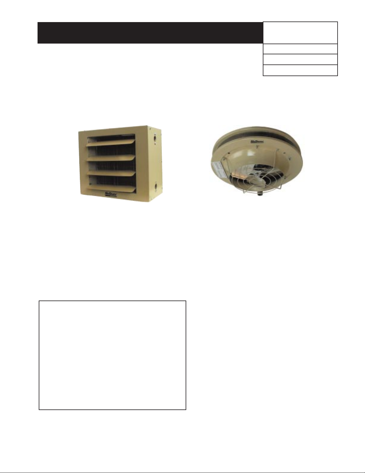
Hydronic Unit Heater
Part Number: # 107115400
Date: June 1999
Installation and maintenance are to be performed only by qualified personnel who are familiar with and in compliance
with state, local and national codes and regulations, and experienced with this type of equipment.
Caution: Sharp edges and coil surfaces are a potential injury hazards. Avoid contact with them.
©1999 AAF-McQuay Incorporated
Hydronic Unit Heaters - for Steam or Hot Water
Horizontal and Vertical Air Delivery
Installation Instructions
Installation & Maintenance Data
IM 217
1. In case of damage, report immediately to the
freight carrier and the company you purchased
the unit from.
2. Check data plate on unit to verify the model,
output, type of unit and power requirements
meet your requirements.
CAREFULLY FOLLOW THE INSTALLATION
PROCEDURE GIVEN IN THIS MANUAL.
Failure to install as shown will void all warranties
Horizontal Unit Heater Vertical Unit Heater
General Information
This manual covers proper installation and service for
standard horizontal and vertical air flow units. Unit heaters
should be installed following directions in this manual for
proper performance and application to terms and
conditions of manufacturer's warranty.
Units are approved for use with water or steam up to
150 psig at 375˚F. Maximum steam or hot water
temperatures for explosion-proof units is 329˚F.
All unit electrical service is approved and certified by
the Canadian Standards Association.
Standard horizontal units are suited for air throw over
general-use areas.
Vertical units are mounted near high ceilings with
vertical projection to mix air and eliminate temperature
stratification.
Steam must enter the unit at the top header and
condensate removed at the lower header. Hot water
supply should be at the bottom header and return at the
top header, keeping the element filled and removing
entrained air through the top of the unit.
Model numbers correspond to MBTU/h output at 2
psig steam with 60˚F entering air. A model 63 will deliver
63,000 BTU/hr. at 2 psig with 60˚F entering air.
CONTENTS
Inspection . . . . . . . . . . . . . . . . . . . . . . . . . . . . . . . . . . . . . . . . 1
General Information . . . . . . . . . . . . . . . . . . . . . . . . . . . . . . . . 1
Installation
Special precautions and location . . . . . . . . . . . . . . . . . . . 2
Mounting height . . . . . . . . . . . . . . . . . . . . . . . . . . . . . . . . 2
Suspension . . . . . . . . . . . . . . . . . . . . . . . . . . . . . . . . . . . . 3
Installing air diffusers . . . . . . . . . . . . . . . . . . . . . . . . . . . . 4
Piping. . . . . . . . . . . . . . . . . . . . . . . . . . . . . . . . . . . . . . . . . 5
Wiring . . . . . . . . . . . . . . . . . . . . . . . . . . . . . . . . . . . . . . . . 6
Operation . . . . . . . . . . . . . . . . . . . . . . . . . . . . . . . . . . . . . . . . . 6
Features . . . . . . . . . . . . . . . . . . . . . . . . . . . . . . . . . . . . . . . . . . 7
Performance . . . . . . . . . . . . . . . . . . . . . . . . . . . . . . . . . . . . 8-11
Dimensions / Motor Data . . . . . . . . . . . . . . . . . . . . . . . . . 12-13
Troubleshooting . . . . . . . . . . . . . . . . . . . . . . . . . . . . . . . . . . . 14
Maintenance . . . . . . . . . . . . . . . . . . . . . . . . . . . . . . . . . . . . . . 15
Warranty. . . . . . . . . . . . . . . . . . . . . . . . . . . . . . . . . . Rear Cover
Page 2
INSTALLATION
Special Precautions
1.Disconnect power supply before making wiring
connections to prevent electrical shock and equipment
damage. All units must be wired strictly in accordance with
wiring diagram furnished with unit.
2.Units should not be installed in atmospheres where
corrosive fumes or sprays are present.
3.Units with power codes A, G, B, or I (UDH and UHH) must
not be installed in potentially explosive or flammable
atmospheres.
4.Be sure no obstructions block air intake or air discharge of
unit heater.
5.Do not install unit above recommended maximum
mounting heights or below the minimum height of eight
feet.
Locating Unit Heaters
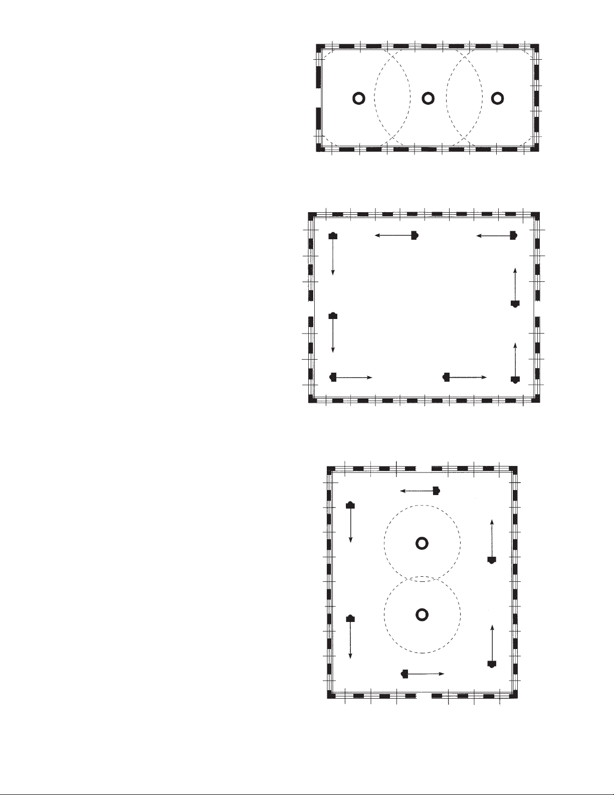
1. Locate horizontal delivery unit heaters so air streams of
individual units wipe the exposed walls of the building
without blowing directly against the walls. Heaters should
be spaced so the air stream from one supports the air
stream from another heater. See Figure 2.
2.Columns, machinery, partitions, and other obstacles
should not interfere with air streams from unit heaters.
3. Unit heaters installed in a building exposed to a prevailing
wind should be located to direct a major volume of heated
air along the windward wall of the building.
4. Large expanses of glass, or large doors that are frequently
opened, should be covered by long-throw unit heaters.
5. Vertical delivery unit heaters should generally be located in
the central area of the space to be heated. Place horizontal
delivery units along the walls of the same building where
heat loss is usually greatest. See Figure 3.
6. Arrange horizontal delivery units so they do not blow
directly at occupants. Air streams from this type of unit
should be directed down aisles, into open spaces on the
floor, or along exterior walls.
7. When only vertical delivery units are installed, they should
be located so exposed walls are blanketed by their air
streams. See Figure 1.
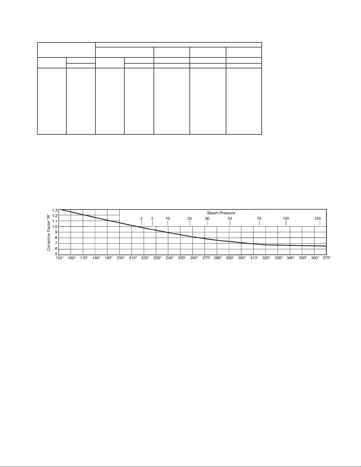
Mounting Height
Do not install unit above recommended maximum mounting
heights or below the minimum height of eight feet. Height at
which unit heaters are installed is critical. Maximum mounting
heights for all units are listed in Table 1. Maximum mounting
heights for vertical models are given for units with or without
optional air deflectors. The data in Table 1 is based on
operating conditions of 2 lbs. steam or 220˚F entering water
with 60˚F entering air. When operating conditions are other
than those above, refer to Figure 4 for maximum mounting
height correction factor. To obtain the maximum mounting
height and throw at actual operating conditions, multiply the
appropriate factor from Figure 4 by the mounting height in
Table 1. The maximum mounting height for all units is that
height above which the unit heater will not deliver heated air
to the floor at operating rating conditions.
Page 2 / IM 217
Figure 1
Unit Locations of Vertical Units in Narrow Buildings
Figure 2
Horizontal Delivery Unit Location
Figure 3
Combination Horizontal and Vertical Delivery Unit Installation
Page 3
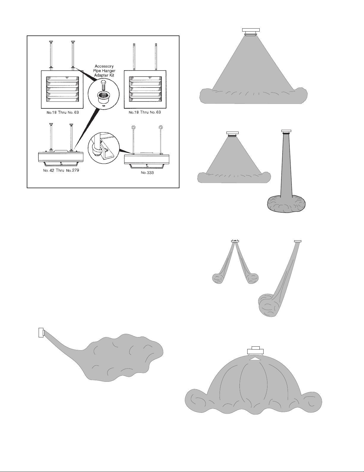
Horizontal delivery units - No. 18 - No. 86 units have two
tapped holes (3/8"-16) in the top for unit suspension. No.
340 units have two tapped holes (1/2" - 13) in the top for
unit suspension. Piping support hangers or clamps are
recommended and should be placed as close to the unit
heater as possible. Independent suspension can be made
with threaded rods or ceiling hanger brackets. See Figure 5.
Vertical delivery units. Vertical delivery Models 42 through
279 have four tapped holes (1/2" - 13) in the top cover for
unit suspension. Unit suspension for these models can be
made-with threaded rods, pipes or ceiling hanger brackets.
This No. 333 vertical unit is equipped with an angle-iron
mounting bracket that has eight 5/8-inch diameter hanger
holes permitting hook-hoisting and suspension with cables,
if desired. A 1/2-inch U-bolt, 3-inch center can be inserted
in the two holes at each end of the bracket to accommodate
suspension with four threaded rods, pipes or hanger
brackets.
Note: A pipe hanger adapter kit as illustrated in Figure 5 is available as an
accessory. The kit consists of two drilled 3/4 inch I.P.S. pipe caps and two
1/2"-13 x 1-3/4" capscrews to facilitate threaded-pipe suspension. One kit
will mount a horizontal delivery unit. Two kits are required to mount a vertical
delivery unit.
Page 3 / IM 217
Unit Suspension
Figure 4
Maximum Mounting Heights Correction Factors
These correction factors are to be used as multipliers to correct the maximum recommended mounting heights and throw of unit heaters
when operated with steam pressures other than 2 pounds or with water at other than average temperature of 220˚F.
INSTALLATION
VERTICAL TYPE WITH DEFLECTORS
HORIZONTAL TYPE* Jet Directional
No Deflector Diffuser Cone Louvers
Model Height-Ft. Model Height-Ft. Height-Ft. Height-Ft. Height-Ft.
No. Std. No. Std. Std. Std. Std.
18 8 42 11 15 8 13
24 9 59 14 19 9 16
33 10 78 15 20 11 17
47 12 95 15 20 11 17
86 15 161 20 27 14 23
108 17 193 22 30 16 25
121 16 212 22 30 16 25
165 19 247 26 34 17 30
193 18 279 30 37 18 35
258 19 333 30 37 17 35
290 20
340 20
* With horizontal louvers opened 30˚ from the vertical plane.
Mounting heights are maximum for heaters operating at standard conditions (2 lbs. steam or 220˚F water with 60˚F entering air). Heights listed for Directional
Louver or Jet Diffuser are with deflectors in fully-opened position. Refer to Fugure 4 for correction of mounting heights under other operating conditions.
Maximum mounting height will be reduced as entering air temperatures exceed 60˚F.
Table 1 — Maximum Mounting Heights
Page 4
Page 4 / IM 217
Deflector Mounting
If an optional air deflector has been furnished for a unit, it is
always shipped separately and can be attached to the unit
before suspension. Vertical louvers for horizontal units can also
be added and positioned before installation. Cone-jet and
louver-type deflectors must be attached with angle brackets
and machine screws to the bottom cover of the unit. Refer to
mounting instructions which are furnished with each deflector.
Depending on supply or return piping arrangement, there is
a possibility of interference between certain Anemostat air
deflectors and piping on some vertical air delivery unit heaters.
Check dimensions.
INSTALLATION
Units are equipped for suspension with threaded rod. Suspension by
pipe is alternate method and requires Accessory Pipe Hanger Kit(s).
Figure 5
Unit Suspension
Figure 7
Vertical Delivery without Deflector
Figure 8
Vertical Delivery with Jet Diffuser
Figure 9
Vertical Delivery with Directional Louvers
Figure 6
Horizontal Unit Delivery
Figure 10
Vertical Delivery with Cone
Page 5
Page 5 / IM 217
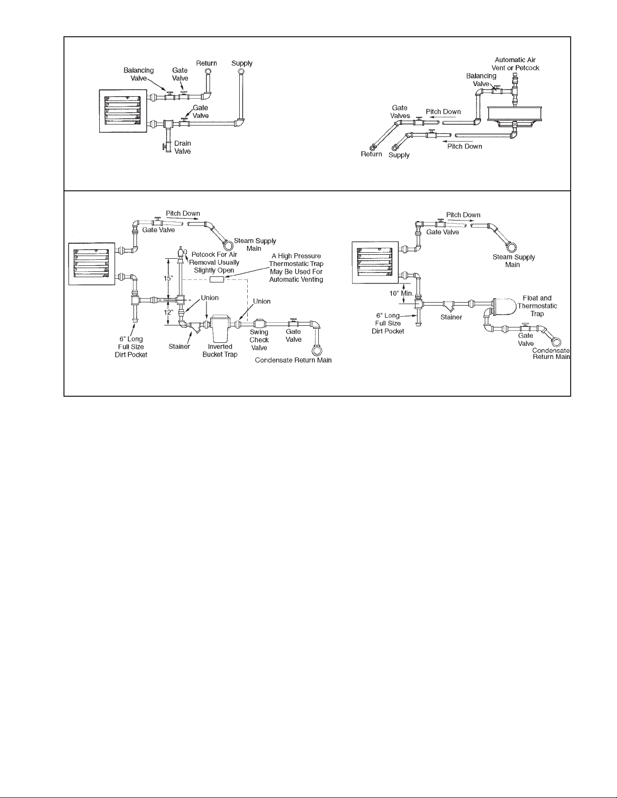
1. Branch piping to and from unit heater should be the
same or larger size as unit connections and include
swing joints to allow for expansion and contraction of the
piping without placing a strain on the unit heater element.
On steam systems, the branch piping should be taken off
and returned above the centerline of the supply and
return lines.
2. Install pipe unions and shut-off valves in lines to and from
each unit heater to allow maintenance or replacement of
unit without shutting down and draining entire system.
For hot water systems, include a balancing valve in return
line for water flow regulation. A drain valve should also be
provided below each unit heater to allow removal of
water from the heating coil if located in an area subject to
freezing.
3. In steam or hot water systems, rapid air removal is
required because entrained air is a cause of corrosion.
Hot water systems should be equipped with suitable air
vent valves for rapid and complete removal of air at the
high points and ends of both supply and return mains.
Proper air venting for steam systems can be achieved by
use of a steam trap with an internal air vent.
4. Traps must be located below the outlet of the unit.
Consult trap manufacturer for specific recommendations. Each steam unit heater should be provided with
a trap of sufficient size and capacity to pass a minimum
of two times the normal condensate released by the unit
at the minimum differential pressure in the system. Trap
capacity is based on the pressure differential between
supply and return mains. Steam systems should be
equipped with a float and thermostatic trap or an inverted
bucket trap with an air bypass.
5. It is advisable to use a pipe line strainer before each
steam trap draining a unit heater. This protection will
reduce the maintenance of the steam trap. When
strainers are used they should be installed between the
unit heater and the trap and be the same size as the trap
tapping. In order to catch dirt and scale, the strainer
should have a screen perforation size smaller than the
trap orifices.
6. On systems where the steam supply to the unit heater is
modulated or controlled by a motorized valve, a vacuum
breaker should be installed between unit outlet and the
trap. If a vacuum breaker is used, it should be in
conjunction with a float and thermostatic trap.
7. Install a dirt pocket at bottom of unit heater to collect dirt
and scale as shown in illustrations. Pipe diameter must
be the same size as unit connections and about six
inches long.
8. Provide adequate pipe hangers, supports, or anchors to
secure the piping system independently of the unit
heater.
Figure 11
Suggested Piping Arrangements
Horizontal Unit Heater Connected to
Overhead Hot Water Mains
Vertical Unit Heater Connected to
Lower Hot Water Mains
Unit Heater Connection for High Pressure Steam
Unit Heater Connection for Low-Pressure
Steam - Open Gravity or Vacuum Return System
Hot Water Systems
Steam Systems
Piping
Page 6

Page 6 / IM 217
INSTALLATION
Wiring Instructions
Disconnect power supply before making wiring connections
to prevent electrical shock and equipment damage. All units
must be wired strictly in accordance with wiring diagram
furnished with unit.
All wiring must be done in accordance with the National
Electric Code and applicable local codes. In Canada, wiring
must conform to the Canadian Electric Code. Power supply
to these unit heaters must be protected by a fused
disconnect switch. It is recommended that all wiring be
adequately grounded.
Electric wiring must be sized to carry the full load amp
draw of the motor, starter, and any control that are used with
the heater. All units with power codes B, I or L (polyphase
motors) must be provided with suitable overcurrent
protection in circuit supplying heater at installation.
Overcurrent protectors should be sized based on motor
current rating shown on the unit serial plate, and applicable
national electric code procedures.
All units are provided with an electrical junction box.
Junction boxes are either integral to the motor or attached to
the unit casing. Units with explosion-proof motors have an
explosion proof junction box attached to the motor.
Any damage to or failure of units caused by incorrect
wiring of the units is not covered by standard warranty.
See rear cover.
Location of room thermostat should be in the natural
circulating path of room air. Mount thermostat about five feet
above floor level where it will not be affected by heat from the
unit or other sources of drafts that would prevent it from
properly controlling room temperature. See instructions
packed with the thermostat.
Speed controllers furnished with specified unit heater fan
motors, are packed separately and must be connected
according to wiring diagram with each controller. Controllers
are not interchangeable with different motor sizes or
manufacturers and must be specifically wired to their
respective motors.
OPERATION
Prior to Operation
1. Make sure fuses are installed in fused disconnect
switches.
2. Check all electrical connections to assure they are secure.
3. Check rigidity of unit mounting. Tighten all fasteners, if
necessary.
4. Inspect piping, strainers, traps, fittings, etc.
Initial Start-Up
1. Set thermostat to lowest position.
2. Turn on power supply to unit.
3. Open return gate valve, and then open supply gate valve
to unit.
4. Raise thermostat setting to desired position.
5. Adjust louvers (if provided) for desired heat distribution.
6. To insure proper sequence of operation, cycle unit on and
off a few times by raising and lowering thermostat setting.
7. Check for proper rotation of fan. All fans must rotate in a
counterclockwise direction when viewed from the back
(UH) or top of the unit heater (UD).
Automatic Control Operations
Install one of the following operating systems for continuous
automatic control.
Intermittent Fan Operation - Hot Coil - A room thermostat
starts and stops the fan motor. An aquastat is sometimes
strapped to the supply or return piping to prevent fan
operation when heat is not being supplied to the unit heater.
Continuous Fan Operation - Intermittent Hot/Cold Coil - A
room thermostat controls a valve which opens to allow steam
or hot water to supply the unit and closes to shut off the
supply when the thermostat is satisfied.
Page 7

Page 7 / IM 217
Connections - Female NPT pipe connections for unit sizes 18 to
165 are located on right side, facing unit. For sizes 193 to 340,
upper connection is on the left side and lower connection is on the
right.
Vertical fins - Less opportunity for dust and dirt to collect. Reduces
cleaning. Fins die-formed for added strength and heat transfer.
Coil - All air passes through coil. Heating is uniform. Design assures
maximum control over air delivery and temperature of air leaving the
heater. Aluminum fins die-formed for added strength - increased
heat transfer. Fins mechanically bonded to serpentine copper tube.
Motor - All motors are totally enclosed. Single phase standard-duty
and explosion-proof types include built-in thermal overload
protection. Built by reputable manufacturers to NEMA standards.
Selected and tested for operation on specific unit heater models. All
motor wiring is terminated in an electrical junction box either
supplied on the unit heater or as an integral part of the motor.
Fan - Lightweight aluminum blades accurately balanced and
pitched to move air quietly and positively - with minimum power
requirement.
Deflector blades - Adjustable horizontal air-deflector blades are
standard - vertical blades are optional on horizontal models.
Safety fan guard - Standard equipment. Bolted steel rod fan guard
completely surrounds the fan offering constant protection.
Casings - Baked-on enamel high solids paint is applied over rust
and corrosion-treated steel for long life. Precision, die-formed
casings.
Motor-Cooling Cone -
Shields motor from coil heat prolongs life of insulation,
windings, and lubricant.
Prolongs motor life.
Coil - Aluminum fins
mechanically bonded to tubes
for maximum heat transfer. All
steam- and water-carrying
passages between heavy
steel pipe connections are
copper.
Motor - All motors are totally
enclosed. Single phase types
include built-in thermal
overload protection. Motors
selected and tested for
operation on each specific
model.
Fan - Aluminum blades are
accurately balanced to
operate quietly and at lowest
possible power consumption.
Junction Box - Easier
installation with single point
electrical connection.
Motor easily removable -
Our design permits motor to
be removed through opening
below the unit especially
important where heaters are
installed close to ceiling.
Vertical fins - Less
opportunity for dust and dirt
to collect. Exposed for easy
cleaning with air hose and
brush.
Casings - Baked-on enamel
high solids paint applied over
rust- and corrosion-treated
steel lasts longer.
Operation
Figure 12
Horizontal Delivery Unit
Figure 13
Vertical Delivery Unit
Page 8

Page 8 / IM 217
AIR DATA MOTOR DATA
* Max. * Heat Lower Heat Final
Mounting Throw or Mtg. Throw Outlet Air Condensate ** Approx.
Type Model Btu/hr. Sq. Ft. Sound Height Spread Height @ Lower ✝Cfm Velocity Temp. Lbs/hr. Hp Rpm
No. Edr. Class (ft.) @ Max. (ft.) Mtg. (Fpm) (˚F)
Height Height
18 18,000 75 II 8 17 — — 340 625 107 18 1/60 1550
24 24,000 100 II 9 18 — — 370 695 119 25 1/25 1550
33 33,000 138 II 10 21 — — 630 690 108 35 1/25 1550
47 47,000 196 III 12 28 8 33 730 810 119 49 1/12 1550
63 63,000 263 III 14 29 8 39 1,120 690 11 66 1/12 1550
HORIZONTAL 86 86,000 358 III 15 31 10 43 1,340 835 118 89 1/8 1625
DELIVERY 108 108,000 450 III 17 31 10 43 2,010 790 109 111 1/8 1625
121 121,000 504 III 16 25 10 38 1,775 715 122 126 1/6 1075
165 165,000 688 IV 19 40 10 56 3,240 880 106 170 1/3 1075
193 193,000 804 IV 18 38 10 53 2,900 810 121 200 1/3 1075
258 258,000 1075 V 19 44 12 60 4,560 750 111 267 1/2 1075
290 290,000 1208 V 20 46 12 60 4,590 765 117 300 1/2 1075
340 340,000 1417 V 20 46 12 56 5,130 735 120 352 1/2 1075
42 42,000 175 II 15 11 — — 950 825 103 43 1/30 1050
59 59,000 246 II 19 14 — — 1,155 1005 111 61 1/30 1050
78 78,000 325 II 20 15 — — 1,590 1065 109 81 1/15 1050
95 95,000 396 II 20 15 — — 1,665 1120 118 99 1/15 1050
139 139,000 579 III 24 18 — — 2,660 1285 112 144 1/6 1075
VERTICAL 161 161,000 671 IV 27 20 — — 2,945 1420 115 167 1/3 1075
DELIVERY 193 193,000 804 IV 30 22 — — 3,500 1690 116 200 1/3 1075
212 212,000 883 IV 30 22 — — 3,610 1740 120 219 1/3 1075
247 247,000 1029 V 34 26 — — 4,820 1910 111 256 1/2 1075
279 279,000 1163 V 37 30 — — 5,460 2165 111 288 1/2 1075
333 333,000 1388 V 37 30 — — 5,980 2165 116 345 3/4 1140
AIR DATA MOTOR DATA
Low * Max. * Heat Final
Speed Mounting Throw or Outlet Air Condensate ** Approx.
Type Model Btu/hr. Sq. Ft. Sound Height Spread ✝Cfm Velocity Temp. Lbs/hr. Hp Rpm
No. Edr. Class (ft.)▲ (ft.) (Fpm) (˚F)
18 14,000 58 I 8 10 220 415 118 14 1/60 1000
24 18,000 75 I 9 11 230 440 131 18 1/25 1000
HORIZONTAL 33 25,000 104 I 10 13 395 440 118 26 1/25 1000
DELIVERY 47 38,000 158 II 12 17 450 515 137 36 1/12 1000
63 47,000 195 II 14 17 685 430 122 49 1/12 1000
86 64,000 265 II 15 19 825 525 131 66 1/8 1000
108 81,000 340 II 17 19 1,255 500 119 84 1/8 1000
PERFORMANCE AT 2 PSI STEAM w/ 60˚F ENTERING AIR
Standard Models at Standard Condtions
High Motor Speeds
PERFORMANCE AT REDUCED MOTOR SPEEDS
Requires Solid State Motor Speed Controller
* Horizontal units with horizontal louvers opened 30˚ from the vertical plane.
Vertical types equipped with cone jet deflector, blades in full open position.
** For most popular motor used on these models.
✝ Cfm for horizontal types is entering Cfm.
Cfm for vertical types is leaving Cfm.
▲ High motor speed.
Page 9

Page 9 / IM 217
AIR DATA MOTOR DATA
* Max. * Heat Lower Heat Final
Pressure Mounting Throw or Mtg. Throw Outlet Air ** Approx.
Type Model Bt./hr. GPM Drop Sound Height Spread Height @ Lower ✝Cfm Velocity Temp. Hp Rpm
No. (Ft. of Class (ft.) @ Max. (ft.) Mtg. (Fpm) (˚F)
Water Height Height
18 12,400 1.3 0.5 II 9 18 — — 340 615 93 1/60 1550
24 16,600 1.7 0.8 II 10 19 — — 370 675 101 1/25 1550
33 21,600 2.2 0.2 II 11 23 — — 630 675 91 1/25 1550
47 30,800 3.2 0.3 III 13 30 8 36 730 785 98 1/12 1550
63 44,800 4.6 0.8 III 15 31 8 42 1,120 680 96 1/12 1550
HORIZONTAL 86 62,600 6.5 1.4 III 16 33 10 46 1,340 820 102 1/8 1625
DELIVERY 108 81,000 8.4 3.2 III 18 33 10 46 2,010 775 96 1/8 1625
121 91,900 9.5 4.0 III 17 27 10 41 1,775 700 107 1/6 1075
165 131,900 13.7 7.9 IV 20 43 10 60 3,240 870 97 1/3 1075
193 145,200 15.1 2.0 IV 19 41 10 57 2,900 790 105 1/3 1075
258 200,500 20.8 5.0 V 20 47 12 65 4,560 740 100 1/2 1075
290 228,600 23.7 5.8 V 22 50 12 65 4,590 750 105 1/2 1075
340 271,200 28.1 11.0 V 22 50 12 60 5,130 720 108 1/2 1075
42 30,300 3.1 0.6 II 16 12 — — 950 825 91 1/30 1050
59 42,900 4.4 0.6 II 20 15 — — 1,155 1005 96 1/30 1050
78 57,200 5.9 0.6 II 22 16 — — 1,590 1065 95 1/15 1050
95 69,800 7.2 0.5 II 22 16 — — 1,665 1120 101 1/15 1050
139 107,400 11.1 2.4 III 26 19 — — 2,660 1285 99 1/6 1075
VERTICAL 161 124,200 12.9 2.2 IV 29 22 — — 2,945 1420 98 1/3 1075
DELIVERY 193 148,800 15.4 1.8 IV 32 24 — — 3,500 1690 102 1/3 1075
212 162,400 16.8 1.4 IV 32 24 — — 3,610 1740 104 1/3 1075
247 189,800 19.7 1.9 V 37 28 — — 4,820 1910 98 1/2 1075
279 214,000 22.2 2.0 V 40 32 — — 5,460 2165 98 1/2 1075
333 261,600 27.1 3.8 V 40 32 — — 5,980 2165 103 3/4 1140
AIR DATA MOTOR DATA
Pressure Low * Max. * Heat Final
Drop Speed Mounting Throw or Outlet Air ** Approx.
Type Model Btu/hr. GPM (Ft. of Sound Height Spread ✝Cfm Velocity Temp. Hp Rpm
No. Water) Class (ft.)▲ (ft.) (Fpm) (˚F)
18 9,800 1.3 0.5 I 9 11 220 400 100 1/60 1000
24 12,000 1.6 0.8 I 10 12 230 425 105 1/25 1000
HORIZONTAL 33 19,000 2.5 0.2 I 11 14 395 430 105 1/25 1000
DELIVERY 47 22,000 2.9 0.3 II 13 18 450 490 105 1/12 1000
63 36,000 4.7 0.8 II 15 18 685 420 105 1/12 1000
86 48,000 6.3 1.4 II 16 20 825 515 115 1/8 1000
108 62,000 8.1 3.2 II 18 20 1,255 490 105 1/8 1000
PERFORMANCE AT 200˚F water w/ 60˚F ENTERING AIR
Standard Models at Standard Condtions
High Motor Speeds
PERFORMANCE AT REDUCED MOTOR SPEEDS
Requires Solid State Motor Speed Controller
* Horizontal units with horizontal louvers opened 30˚ from the vertical plane.
Vertical types equipped with cone jet deflector, blades in full open position.
** For most popular motor used on these models.
✝ Cfm for horizontal types is entering Cfm.
Cfm for vertical types is leaving Cfm.
▲ High motor speed.
Page 10

Page 10 / IM 217
Horizontal Air Delivery Model UH
Dimensional and Motor Data
UH 18-86,
Mounting Holes
3/8” - 16 Tap
UH 108-340,
Mounting Holes
1/2” - 13 Tap
Mounting
Holes
Pipe
Connection
5”
Min.
Note: Piping Connections for unit sizes 18 to 165 are as shown, for sizes 193 to 340, upper
connection is on the left side and lower connection on the right.
Standard
AB C
I
EF GH
Connections Fan
Approx.
Unit
115V Std 115V Ex Prf
NPT Diameter
Shipping
Horizontal
Motor Motor
Wt. Lbs.
18 11-1/2 11-1/2 6 5 12-1/2 5-5/8 2-1/4 4-1/8 7-1/2 1/2 9 16
24 11-1/2 11-1/2 6 6 12-1/2 5-5/8 2-1/4 1-1/8 7-1/2 1/2 9 19
33 15 15 8-3/4 6-1/2 12 10-3/8 3-5/8 6 10 3/4 12 34
47 15 15 8-3/4 8 12 10-3/8 3-5/8 6 10 3/4 12 43
63 18-1/2 18-12 8-3/4 8 12 14-3/8 3-5/8 6 14 3/4 14 55
86 18-1/2 18-1/2 8-3/4 8 12 14-3/8 3-5/8 6 14 3/4 14 55
108 22-1/2 22-1/2 9-1/2 7-1/2 11-1/2 18-3/8 3-5/8 7-5/8 18 3/4 18 78
121 22-1/2 22-1/2 9-1/2 7-1/2 13-1/2 18-3/8 3-5/8 7-5/8 18 3/4 18 81
165 26-1/2 26-1/2 9-1/4 9-1/2 14 22-3/8 3-5/8 7-3/8 22-3/8 3/4 22 100
193 30 30 9-1/4 9-1/2 14 18-1/2 3-5/8 4-3/4 25-1/2 1-1/4 22 105
258 38 38 12-1/2 10-1/2 15 18-1/2 3-5/8 8 33-1/2 1-1/4 22 170
290 38 38 12-1/2 10-1/2 15 18-1/2 3-5/8 8 33-1/2 1-1/4 24 180
340 38 38 12-1/2 10-1/2 15 18-1/2 3-5/8 8 33-1/2 1-1/4 24 200
MOTOR TYPE AND (POWER CODE)
115/60/1 230/60/1 200/60/3 230/460/60/3 115/60/1 230/460/60/3 575/60/3 575/60/3
Model Totally Totally Explosion Explosion Explosion
Number Enclosed Enclosed Totally Totally Proof Proof Proof
w/Thermal w/Thermal Enclosed Enclosed w/Thermal w/Thermal Totally w/Thermal
Overload Overload Overload Overload Enclosed Overload
Horizontal (A) (G) (B) (I) (A) (I) (L) (L)
18 0.8 0.44 — — 3.1 — — —
24 1.6 0.44 — — 3.1 — — —
33 1.6 1.0 — — 3.1 — — —
47 2.2 1.0 1.1 1.4/0.7 3.1 — — —
63 2.2 1.0 1.1 1.4/0/7 3.1 — — —
86 2.3 1.0 1.1 1.4/0.7 3.1 — — —
108 2.3 1.0 1.1 1.4/0.7 3.1 — — —
121 2.8 1.5 1.9 2.1/1.05 4.1 1.5/0.75 0.84 —
165 5.4 2.23 1.9 2.1/1.05 6.1 1.5/0.75 0.84 —
193 5.4 2.23 1.9 1.2/1.05 6.1 1.5/0.75 0.84 —
258 7.5 3.5 2.6 3.0/1.5 7.2 2.0/1.0 0.92 0.76
290 7.5 3.5 2.6 3.0/1.5 7.2 2.0/1.0 0.92 0.76
340 7.5 3.5 2.6 3.0/1.5 7.2 2.0/1.0 0.92 0.76
Code A, G and I motors are totally enclosed with integral thermal overload protection.
Code B and I 3f motors require protection through motor starters.
All dimensions in inches.
Table 2. Model UH dimensions
Table 3. Model UH Motor Ampere Ratings
Page 11

Page 11 / IM 217
DIMENSIONAL/MOTOR DATA
Vertical Air Delivery Model UD
Air Deflectors (Optional)
Model
Male Approx.
Number A B C D E F L M N P Fan Conn. NPT Shipping
Vertical Top Bottom Wt. Lbs.
42 24-3/4 3-5/8 11-3/8 2-1/8 4-3/8 14-1/2 6-1/2 12 10-1/4 6-1/2 14 1-1/4 1-1/4 42
59 24-3/4 5-1/8 11-3/8 2-1/8 4-3/4 14-1/2 6-1/2 12 10-1/4 6-1/2 14 1-1/4 1-1/4 48
78 24-3/4 6-5/8 11-3/8 2-1/8 2-5/8 16-1/2 6-1/2 12 13 6-1/2 16 1-1/4 1-1/4 52
95 24-3/4 8-1/8 11-3/8 2-1/8 2-5/8 16-1/2 6-1/2 12 13 6-1/2 16 1-1/4 1-1/4 55
139 34-3/4 6-7/8 18-3/8 2-1/8 3 19-1/2 7-1/2 13 11-1/4 7-1/2 19 1-1/2 1 78
161 34-3/4 8-3/8 18-3/8 2-1/8 3 19-1/2 7-1/2 13 11-1/4 7-1/2 19 1-1/2 1 91
193 34-3/4 9-7/8 18-3/8 2-1/2 3 19-1/2 7-1/2 13 11-1/4 7-1/2 19 1-1/2 1 100
212 34-3/4 12-5/8 18-3/8 2-1/2 3 19-1/2 7-1/2 13 11-1/4 7-1/2 19 2 1-1/4 115
247 34-3/4 12-7/8 18-3/8 2-1/2 3 21-1/2 8 16 12-3/4 8 21 2 1-1/4 122
279 34-3/4 14-3/4 18-3/8 2-1/2 3 21-1/2 8 16 12-3/4 8 21 2 1-1/4 129
333 43-1/4 14-1/2 24 2-7/8 3-1/8 22-1/2 8-1/2 16 12 8-1/2 22 1-1/2 1-1/2 182
MOTOR TYPE AND (POWER CODE)
115/60/1 230/60/1 200/60/3 230/460/60/3 115/60/1 230/460/60/3 575/60/3 575/60/3
Model Totally Totally Explosion Explosion Explosion
Number Enclosed Enclosed Totally Totally Proof Proof Proof
w/Thermal w/Thermal Enclosed Enclosed w/Thermal w/Thermal Totally w/Thermal
Overload Overload Overload Overload Enclosed Overload
Vertical (A) (G) (B) (I) (A) (I) (L) (L)
42 1.9 1.28 1.9 2.1/1.05 4.1 — 0.84 —
59 1.9 1.28 1.9 2.1/1.05 4.1 — 0.84 —
78 2.4 1.28 1.9 2.1/1.05 4.1 1.5/0.75 0.84 —
95 2.4 1.28 1.9 2.1/1.05 4.1 1.5/0.75 0.84 —
139 2.8 1.5 1.9 2.1/1.05 4.1 1.5/0.75 0.84 —
161 5.4 2.23 1.9 2.1/1.05 6.1 1.5/0.75 0.84 —
193 5.4 2.23 1.9 2.1/1.05 6.1 2.0/1.0 0.84 —
212 5.4 2.23 1.9 2.1/1.05 6.1 2.0/1.0 0.84 —
247 7.5 3.5 2.6 3.0/1.5 7.2 — 0.92 0.67
279 7.5 3.5 2.6 3.0/1.5 7.2 3.5/1.75 0.92 0.67
333 8.8 4.4 3.7 3.4/1.7 — 5.8/2.9 1.24 1.4
* Maximum amp rating as shown on the motor rating plate.
All dimensions in inches.
Table 4. Model UD dimensions
Table 5. Models UD Motor Ampere Ratings
Page 12

Page 12 / IM 217
Fails to Maintain Temperature
1. Undersized unit heater, boiler, pump or piping.
2. Excessive exhaust air (exhaust fans may have been
added since heating installed).
3. Unit heater operating at lower speed when sized to
operate at high speed.
4. Unit heater mounted too high - heated air not delivered
to floor level.
5. Thermostat - improper location or setting, or not
functioning.
6. Dirty or clogged coil.
Unit Blows Cold Air
1. Manual shut-off valve closed.
2. Insufficient steam pressure of lack of hot water.
3. Aquastat not functioning.
4. Improper venting.
5. Steam trap not functioning.
6. Drip leg too short (steam system).
7. Return line plugged (steam system).
8. Pump undersized or not operating (hot water system).
Does Not Operate When Heat Needed
1. Defective motor or electrical connections.
2. Thermostat, aquastat or pressure limit control not
functioning.
Fails to Deliver Heat to Floor
1. Units mounted too high.
2. Operating on low speed.
3. Final air temperature too high.
4. Louvers not adjusted properly.
5. Wrong type of diffuser (on verticals).
6. Undersized unit heater (insufficient air delivery).
7. Wrong type of unit (may require vertical delivery).
8. Cross ventilation or drafts.
9. Obstructions to air flow.
Noisy Unit
1. Loose bolts or screws.
2. Fan blade bent, out of balance.
3. Dirt accumulation on fan blades.
4. Fan hub or blade rivets loose.
5. Motor shaft thrust bearing worn.
6. Motor mounting bent, fan not positioned properly in
venturi.
7. Unit mounted too rigidly, transmits vibration noise.
8. Conduit too rigid, transmits vibration noise.
9. BX cable touching unit heater, chatters as casing
vibrates.
Unit Leaks
1. Loose connection.
2. Internal corrosion.
Employees Complain of Hot Blast
1. Air stream aimed directly at employees.
2. Louvers not adjusted properly.
3. Wrong type of diffuser (on verticals).
4. Excessive final air temperature.
Unit Operates Too Long
1. Thermostat installed on cold wall or otherwise
improperly located.
2. Heavy exhaust fan load. (May have been increased
since heating system was laid out).
3. Aquastat or pressure limit control not functioning
properly.
4. Unit is undersized.
Frequent Motor Failure
1. Voltage fluctuations too high or too low.
2. Excessive or insufficient lubrication.
3. Wiring to motor undersized.
4. Improper electrical connections.
5. Motor operating in too high air temperature.
6. Restricted air flow through unit due to clogged coil,
closed louvers, too much duct work connected to unit.
7. Fan out of balance.
8. Unbalanced voltage on 3 phase power.
Premature Failure
1. Severe internal corrosion due to condition of boiler
water.
Coil Failure
1. Severe internal corrosion from feedwater.
2. Type of boiler treatment.
3. Entrained air causing water hammer.
4. Too much outdoor air portion in freezing temperatures.
5. Continuous operation above 150 PSI (375˚F) (steam
systems).
REPLACEMENT PARTS
All replacement parts and controls are proprietary in that they have all been designed, tested, and approved for the particular
application to insure both physical and electrical fit and performance. Any substitution of parts or controls not approved by
the factory will be at customer's risk.
Note: We reserve the right to substitute parts of advanced design and to change specifications or prices without advance
notice or without incurring obligations.
Replacement parts can be obtained by submitting the model number, power code, control code and serial number
shown on the rating plate attached to the unit, along with a description of the part, to the factory.
SERVICE DIAGNOSIS
Page 13

Page 13 / IM 217
Inspect Regularly
Under average conditions, it is recommended that unit
heaters be inspected before every heating season - more
often in locations where air is contaminated with corrosive
fumes, dust, soot or oil spray. Check for dirty, clogged coils,
excessive vibration and loose connections.
Motors
A. Cleaning
Remove grease and dirt on motor during each
inspection or lubrication. Open frame motors should be
blown clean every heating season, or whenever coils
are cleaned, whichever is sooner.
B. Lubrication
1. Lubricate motor according to manufacturer's
instructions located on the motor.
2. When no motor oiling instructions are on the motor,
oil the motor every two thousand hours of operation
with SAE20 motor oil for units in normal applications.
Adjust oiling according to usage and atmosphere.
3. Some motors do not have oil fittings. These motors
are lubricated for long life and do not require further
lubrication.
C. Overload Protection
A change in line voltage higher or lower than motor
nameplate rating may cause overheating and serious
motor damage. Check plant voltage conditions. A
separate manual starter with thermal overload
protection device is recommended for those units that
do not have motors with built-in overload protection.
Coils
A. Cleaning
Clean coil at least once a year; more often under
unfavorable conditions. Unless coil is kept reasonably
free of dirt, lint and grease, its original heating capacity
will be reduced - possibly to a serious degree, and
motor damage may result.
Two commonly used cleaning methods are:
1. Loosen dirt by brushing fins on side where air enters
coil and then turn on fan to blow dirt from unit.
2. Use high pressure air hose to loosen dirt by blowing
from side where air leaves coil (side adjacent to
louvers on blow-through units; side adjacent to fan
on draw-through units).
For thorough cleaning of coil, remove motor and fan
and spray a mild alkaline cleaning solution over the coil.
After a few minutes, follow by a hot water rinse. (A
steam gun can be used for spraying cleaning solution
and hot water.)
Coils subjected to corrosive fumes should be checked
and cleaned frequently.
B. Internal Corrosion Safeguards
1. Provide controlled water treatment - don't use
excess of boiler compounds. Contact your boiler
compound supplier for proper usage or the services of
a water treatment laboratory.
2. Periodic internal flushing of the coils is recommended in
areas where water supply is suspected of causing
scale. Use an alkaline-cleaning solution and introduce it
at the main pump of the hydronic system. Flush
thoroughly.
WARNING: USING INORGANIC OR MINERAL ACIDS
SUCH AS MURIATIC (HYDROCHLORIC) ACID, EVEN
THOUGH INHIBITED, MAY LEAD TO SEVERE
DAMAGE, INCLUDING CORROSION AND LEAKAGE.
3. De-aerate boiler feed-water (particularly if large amount
of new water is used).
4. Insure rapid continuous and adequate condensate
drainage by properly sized and installed traps and
piping. Check traps for sticking. Clean strainers ahead
of traps. (When traps don't work, condensate
accumulates in unit heater coil; water hammer results.)
5. Adequately vent each unit.
6. Use low pressure steam when possible.
Casings
A. Cleaning
Periodic cleaning of casings is recommended to remove
dirt, grease and corrosive substances that may injure
finish. Rusted or corroded spots should be cleaned and
repainted.
B. General Inspection
Tighten fan guard and motor bracket. Check fan for
proper clearance, free rotation and firm connection to
shaft. When servicing is complete, tag unit to indicate
date of inspection, lubrication and cleaning.
MAINTENANCE
SERVICE CHECKLIST
Note to service technician: Fill in data for each unit. Leave this manual with owner as future service record.
Installed Location/Identification __________________________________________________________________________________
Model Number _________________________________________________________________________________________________
Serial Number _________________________________________________________________________________________________
Power Code ___________________________________________________________________________________________________
Control Code __________________________________________________________________________________________________
Date
Installed Service Dates
Proper Service Voltage
Check for Leaks
Check for Corrosion
Clean Condenser Fins
Check Fan Operation
Lubricate Motor
(Non-Detergent SAE 200)
Serviced By (initials)
Page 14

When writing for service or replacement parts, direct your
letters to McQuay Service, and refer to the model number
and the serial number of the heater as stamped on the serial
plate attached to the heater kit. If replacement parts are
required, give the date of the heater kit installation and the
date of the failure; also, give description of replacement
parts and explanation of malfunction.
Replacement Parts
AAF-McQuay Incorporated
4900 Technology Park Boulevard, Auburn, New York 13021-9030 USA (315) 253-2771
Printed on recycled paper containing at least 10% post-consumer recycled material.
Unit heaters used under excessive pressures or temperatures may
have failures to the heat exchanger not covered under our warranty.
Unit heaters used in the presence of corrosive compounds may
have failures to the heat exchange not covered under our warranty.
TO PREVENT PREMATURE HEAT EXCHANGER FAILURE, DO NOT
SUBJECT UNITS TO TEMPERATURES OR PRESSURES ABOVE
THE STATED LIMITATIONS.
DO NOT LOCATE ANY UNIT IN AREAS WHERE CAUSTIC VAPORS
ARE PRESENT IN THE ATMOSPHERE.
 Loading...