

Page 1

266-7-07-7
Page 2

TABLE OF CONTENTS
Page
NOTICE TO OWNERS AND OPERATORS ......................................... 1
SAFETY TIPS ............................................................... 2
INSTALLATION ............................................................ 3-6
OPERATION ................................................................ 7
TO PROCESS PRODUCT ............................................... 7-8
CLEANING PROCEDURE ...................................................... 9
MAINTENANCE .............................................................10
GENERAL ............................................................10
LUBRICATION ......................................................11-12
WALL CHART (PART No. 671) ..................................................12
PARTS DIAGRAMS ........................................................13-20
SWITCH ASSEMBLIES AND SERVICE PARTS ......................................21
WIRING DIAGRAMS........................................................22-24
WARNING LABEL LOCATIONS ON MACHINE ......................................25
WEARABLE SAW PARTS ......................................................26
PARTS LIST/ORDERING.......................................................27
PARTS ASSEMBLIES LIST/ORDERING ...........................................28
OPERATOR’S SIGNATURE PAGE................................................29
LIMITED WARRANTY .........................................................30
NOTICE TO OWNERS AND OPERATORS......................................................................1
SAFETY TIPS........................................................................................................................2
INSTALLATION...............................................................................................................3-6
OPERATION........................................................................................................................7
TO PROCESS PRODUCT.........................................................................................8
CLEANING PROCEDURE.................................................................................................9
MAINTENANCE...............................................................................................................10
GENERAL................................................................................................................10
LUBRICATION..................................................................................................11-12
WALL CHART(PART NO. 671).......................................................................................12
OPERATOR’S NOTES.......................................................................................................13
PARTS DIAGRAM........................................................................................................14-22
OPERATOR’S NOTES.......................................................................................................16
SWITCH ASSEMBLIES AND SERVICE PARTS..............................................................23
WIRING DIAGRAMS...................................................................................................24-28
WARNING LABEL LOCATIONS ON MACHINE..........................................................29
WEARABLE SAW PARTS..................................................................................................30
PARTS LIST/ORDERING..................................................................................................31
PARTS ASSEMBLIES LIST/ORDERING..........................................................................32
OPERATOR’S SIGNATURE PAGE...................................................................................33
LIMITED WARRANTY......................................................................................................34
Page 3
BIRO’s products are designed to process food products safely and efficiently. Unless the operator is properly trained and supervised, there is the possibility of a serious injury. It is the responsibility of the owner to assure that this machine is used properly and safely, strictly following the
instructions contained in this Manual and any requirements of local law.
No one should use or service this machine without proper training and supervision. All operators should be thoroughly familiar with the procedures contained in this Manual. Even so BIRO
cannot anticipate every circumstance or environment in which its products will be used. You, the
owner and operator, must remain alert to the hazards posed by the function of this equipment –
particularly the SHARP MOVING BAND TYPE SAW BLADE. No one under eighteen (18) years of
age should operate this equipment. If you are uncertain about a particular task, ask your supervisor.
This Manual contains a number of safe practices in the SAFETY TIP section. Additional warnings are placed throughout the Manual. Warnings related to your personal safety are indicated by:
Warnings related to possible damage are indicated by:
BIRO also has provided a wall chart to be posted near the equipment. If any warning label, wall
chart, or Manual becomes misplaced, damaged, or illegible, please contact your nearest Distributor or BIRO directly for a replacement.
Remember, however, this Manual or the warning labels do not replace the need to be alert and
to use your common sense when using this equipment.
1
NOTICE TO OWNERS AND OPERATORS
OR
- NOTE -
A copy of this manual is included with each Model 1433 saw.
The descriptions and illustrations contained in this manual are not binding.
The manufacturer reserves the right to introduce any modification without
updating the manual.
Page 4
Page 5

4. To assemble meat guage plate (Part No. A14275) to the machine; Loosen the lock knob (Part No. 272-10)
on the right side meat guage bracket. Remove the meat guage gear rack (Part No. 14272) and insert into the
meat gauge plate. Be sure to hold meat gauge arm so that the release handle is depressed. Re-install the gear
rack by first inserting the rectangle end into the left hand meat gauge bracket, then swing the right hollow
round end of the gear rack into the original lock position. Upon aligning the gear rack with the capscrew
(Part No. 272-11), tighten the lock knob clockwise, fastening the locking cap screw into the hollow end to
the gear rack, CHECKING for a secure assembly. Keep gear rack well oiled with food grade oil to ensure
free movement.
SLIDE GIBS
HEAD
BASE
3
Page 6

6.
7.
REMOVAL
Page 7

7A.
Page 8
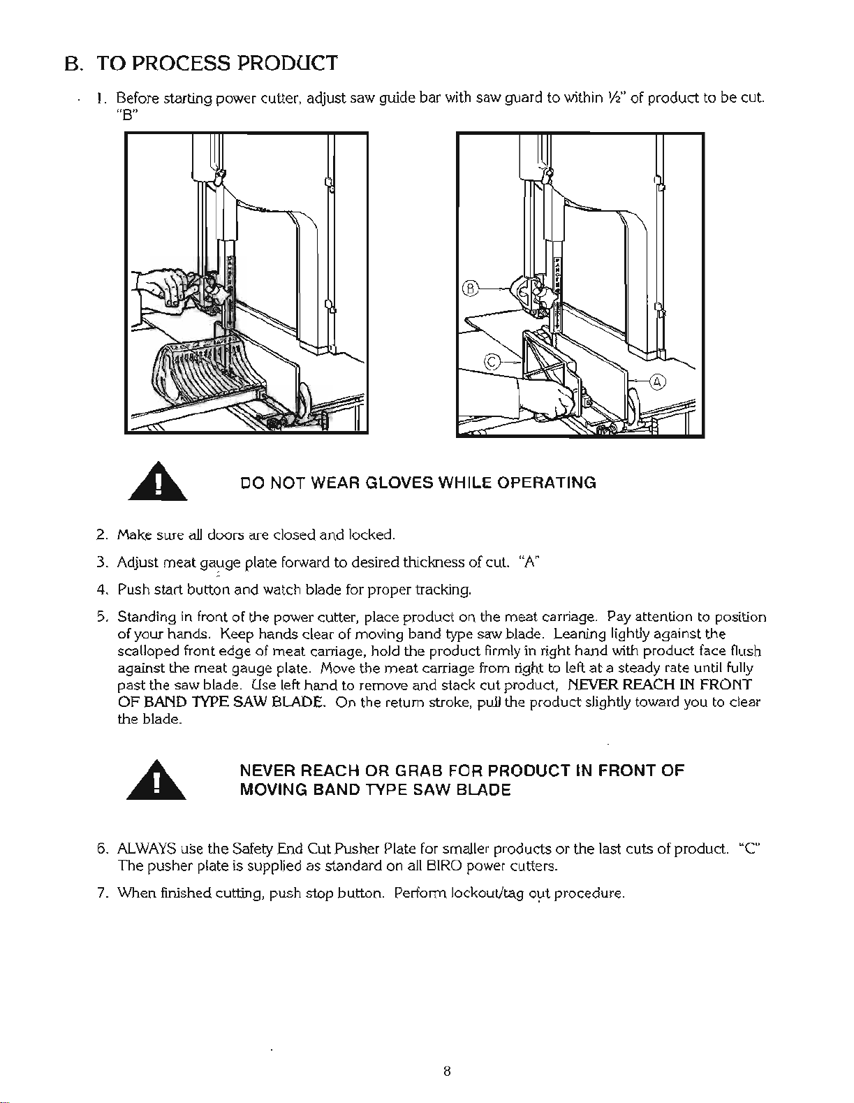
14. Make sure saw guide bar with saw guard is in its lowest position. Close head and base doors.
15. Push start button and check for proper phasing of motor. Blade should be traveling down through saw guide.
16. Watch for proper tracking of blade. Back of blade should be centered in hole in saw guide in stationary bar (Part
No. 119A). Push stop button to stop machine.
17. Check placement of all warning labels, wall chart and Manual. Machine is ready for trained operators to process
product.
18. Contact your local Distributor or BIRO directly if you have any questions or problems with the installation or
operation of this machine.
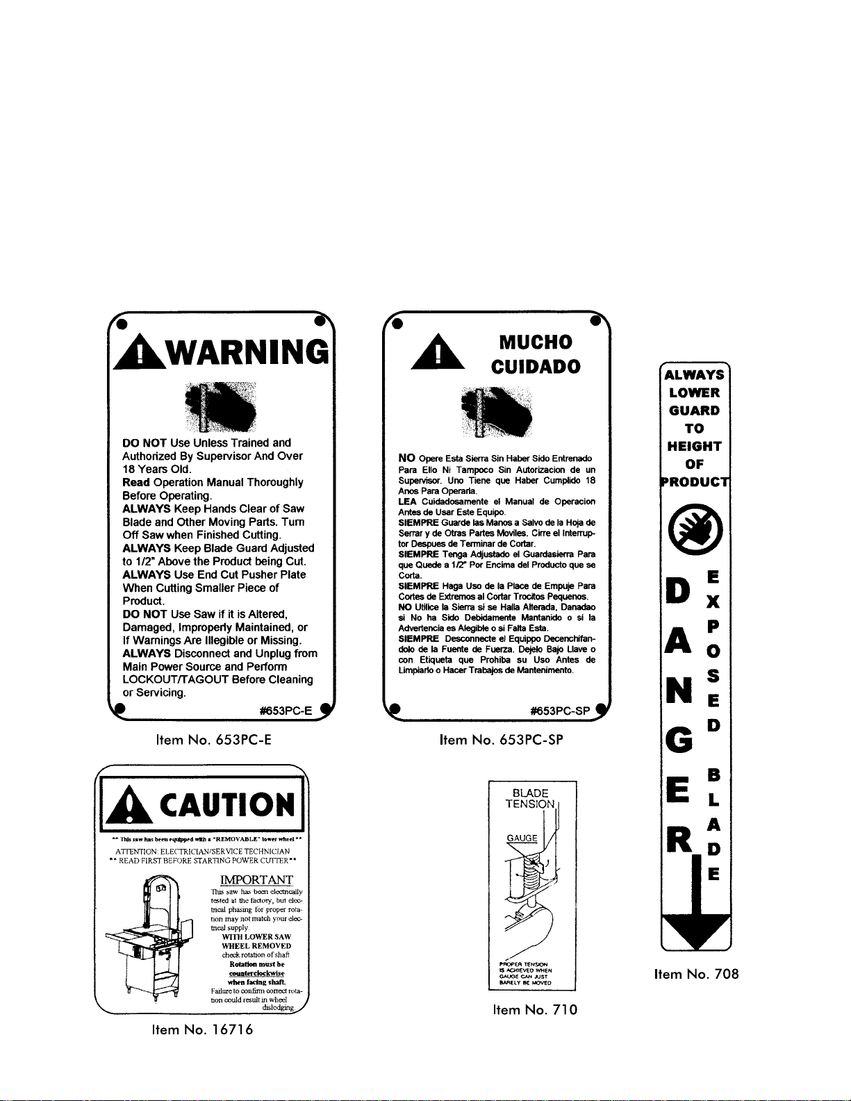
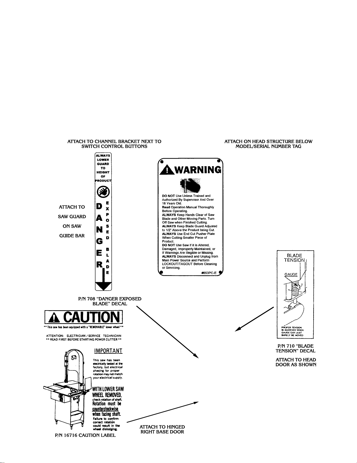
WARNING LABELS AND WALL CHART
FOR BIRO POWER CUTTERS
SEE PAGE 11 AND 24 FOR LOCATIONS ON THIS MACHINE
6
SEE PAGE 12 AND 29 FOR LOCATIONS ON THIS MACHINE
Page 9

7
Page 10
Page 11
CLEANING
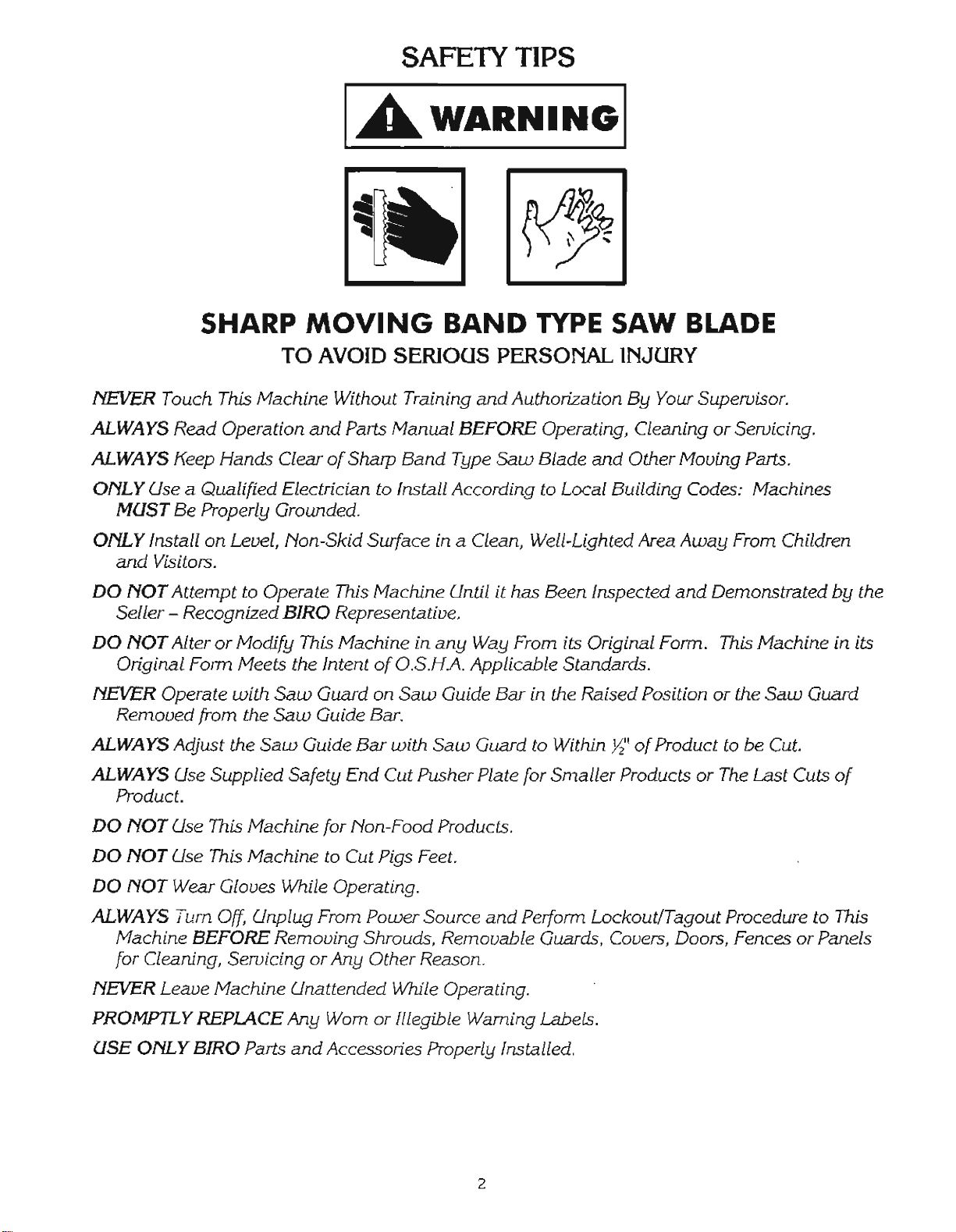
SHARP MOVING BAND TYPE SAW BLADE
TO AVOID SERIOUS PERSONAL INJURY
ALWAYS Turn Off, Unplug From Power Source and Perform Lockout/Tagout Procedure to This
Machine BEFORE Cleaning or Servicing.
ONLY Use Recommended Cleaning Equipment, Materials and Procedures.
NEVER Spray Water or Other Liquid Substances Directly at Motor, Power Switch or any Other
Electrical Components.
ALWAYS Thoroughly Clean Equipment at Least Daily.
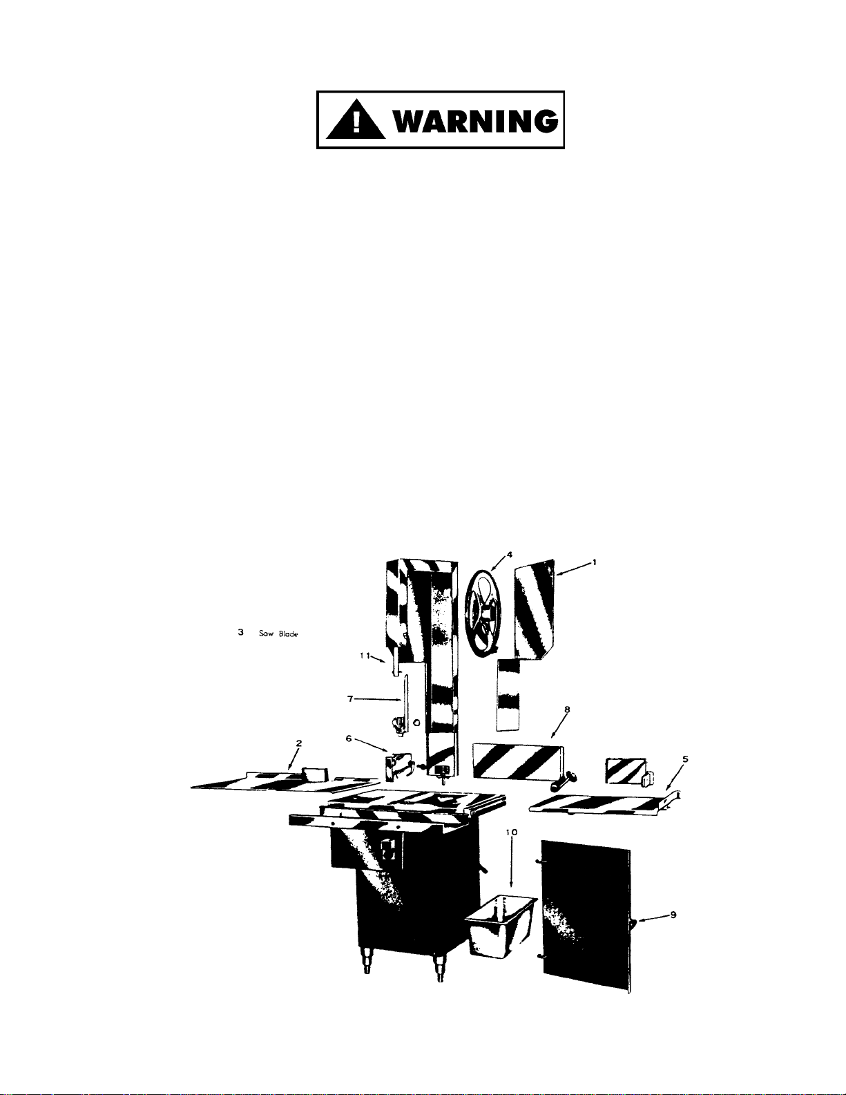
CLEANING THE BIRO POWER CUTTER:
Disconnect electrical power to the machine before cleaning. Parts to be removed have been made accessible and can
be removed without tools. Notice in the drawing below that all parts are numbered. Each part should be removed for
cleaning in the numbered sequence shown. To ensure cleaner cuts, keep the parts on the cleaning system in good
condition. Parts on the cleaning system which should be checked weekly, and changed as required are as follows:
Wheel Cleaners (Part No. 179), Saw Cleaners (Part No. 131), Saw Guide in Stationary Bar (Part No. 119A), Upper Saw
Guide (Part No. 602B), Lower Blade Back-Up Guide (Part No. S608) and Nylon Filler (Part No. 177).
9
Page 12

SAW GUIDE BAR:
Page 13

e. STATIONARY BAR ASSEMBLY: Check condition of nylon filler (Part No. 177), change every four (4) weeks.
Check condition of saw guide (Part No. 119A), check tracking of blade through guide, back of blade should
be centered in hole, replace every six (6) months. Check condition of lower blade back-up guide (Part No.
S608). Check adjustment of back-up guide, should have
1
32
² gap between back of blade and saw guide
carbide. Replace every six (6) months.
f. SAW CLEANERS: Check condition of blade cleaners, replace every four (4) weeks.
g. RATCHET ASSEMBLY: Check for smooth operation through full range of travel. Check condition of trigger
spring, replace as necessary.
h. SLIDE GIBS: Check that head structure moves freely up and down. Check for side to side and front to rear
tolerance. Adjust as required. Grease every four (4) weeks.
i. MEAT GAUGE ASSEMBLY: Check free movement of meat gauge plate on gear rack. Gear rack to be kept
lubricated at all times with light food grade oil. Check operation of release handle. Check that worm gear
engages properly with gear rack. Check tension of release handle spring, replace as necessary.
j. MEAT CARRIAGE ASSEMBLY: Check for free movement through full range of travel. Check for side to
side tolerance, adjust as necessary. Check condition and grease bearings, replace as necessary. Check
condition of thumb guard, replace as necessary.
k. SAFETY ITEMS: Safety end cut pusher plate is with machine and accessible. All warning labels are present,
properly affixed and legible. Model and Serial Number plate properly affixed and legible. Wall poster within
operator’s view from machine. Manual accessible to operator.
B. LUBRICATION
1. UPPER WHEEL BEARINGS: Grease every
four (4) months. Change grease every
twelve (12) months.
2. LOWER BEARING HOUSING: Grease
every four (4) months. Change grease every
twelve (12) months.
3. SLIDE GIBS: Grease every four (4) weeks.
4. MEAT CARRIAGE BEARINGS: Grease
every four (4) weeks.
5. SAW GUIDE BAR: Oil daily with food
machine oil.
6. MEAT GAUGE GEAR RACK: Oil daily
with food machine oil.
11
1. Remove the finger lift fastener knob and the fingerlift assembly.
2. Remove the finger lift fastener stud.
3. Push the saw guide bar up and out of the top of the head structure.
4. Remove the saw guide bar spring.
5. Clean and lubricate the babbitt pocket area (the square indented area
that seats the saw guide bar spring).
6. Lower the new saw guide bar spring through the top of the babbitt
pocket area and guide the spring into position with a standard
screwdriver. (NOTE: Drawing)
7. While holding the saw guide bar spring in position, re-enter the saw
guide bar from the top compressing the saw guide bar spring slightly
until the saw guide bar slides past the spring.
8. Replace the finger lift fastener stud, the finger lift assembly and the finger lift fastener knob.
9. Test by making several adjustments.
When lubricating the upper wheel bearing it is important that the three hex
head screws securing the upper wheel hub cap be loosened slightly before at
tempting to pump grease into the grease fitting. Loosening the screws allows
for an escape of old broken down grease and air from the bearing cavity. Failure
to loosen the screws before greasing the upper bearings can cause the upper
shaft seal to be dislodged from the upper wheel allowing grease to escape and
moisture to get into the cavity. When finished greasing the bearings, retighten
the three screws. Take care to also clean off any grease that was forced out of
the cavity during greasing.
Page 14
7. MOTOR BEARINGS: Bearing grease will lose its lubricating ability over time, not suddenly. The lubricating
ability of a grease (over time) depends primarily on the type of grease, the size of the bearing, the speed at which
the bearing operates and the severity of the operating conditions. Good results can be obtained if the following
recommendations are used in your maintenance program.
A high grade ball ro roller bearing grease should be used. Recommended grease for standard service conditions
is Polyrex EM (Exxon Mobil).
Equivalent and compatible greases include: Texaco Polystar, Rykon Premium #2, Pennzoil Pen 2 Lube, and
Chevron SRI.
Recommended lubrications intervals is every 9 months with the equivalent of two (2) teaspoons of grease.
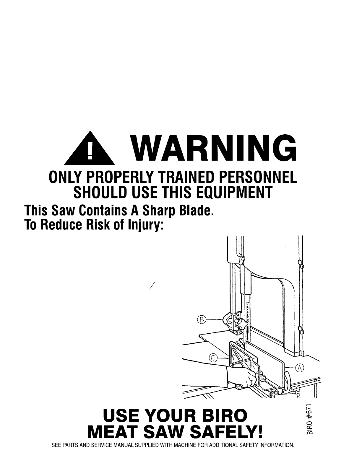
PART NUMBER 671
WALL CHART “BAND SAW SAFETY GUIDELINES”
ATTACH TO WALL IN VICINITY OF MACHINE IN EASY VIEW OF OPERATOR
12
1. Before Using, Make Sure:
+
Gauge Plate
!
And Other Components
Are Secure.
+
All Warning Labels and Guards Are In Place.
+
The Guide Bar
"
Is Adjusted To
1
2
Inch
Above The Product To Be Cut.
2. While Cutting:
+
Keep Hands and Fingers Away From Blade.
+
Keep Product Securely Against Guage Plate.
+
Use End Cut Pusher
#
When Making
Final Cuts. Item No. 256P.
3. Before Cleaning:
+
Turn Off Power And Unplug.
+
Remove Saw Blade.
+
Use Extra Care When Handling The Saw Blade.
Page 15

- NOTES -
13
Page 16

14
Page 17

15
Page 18

- NOTES -
16
Page 19
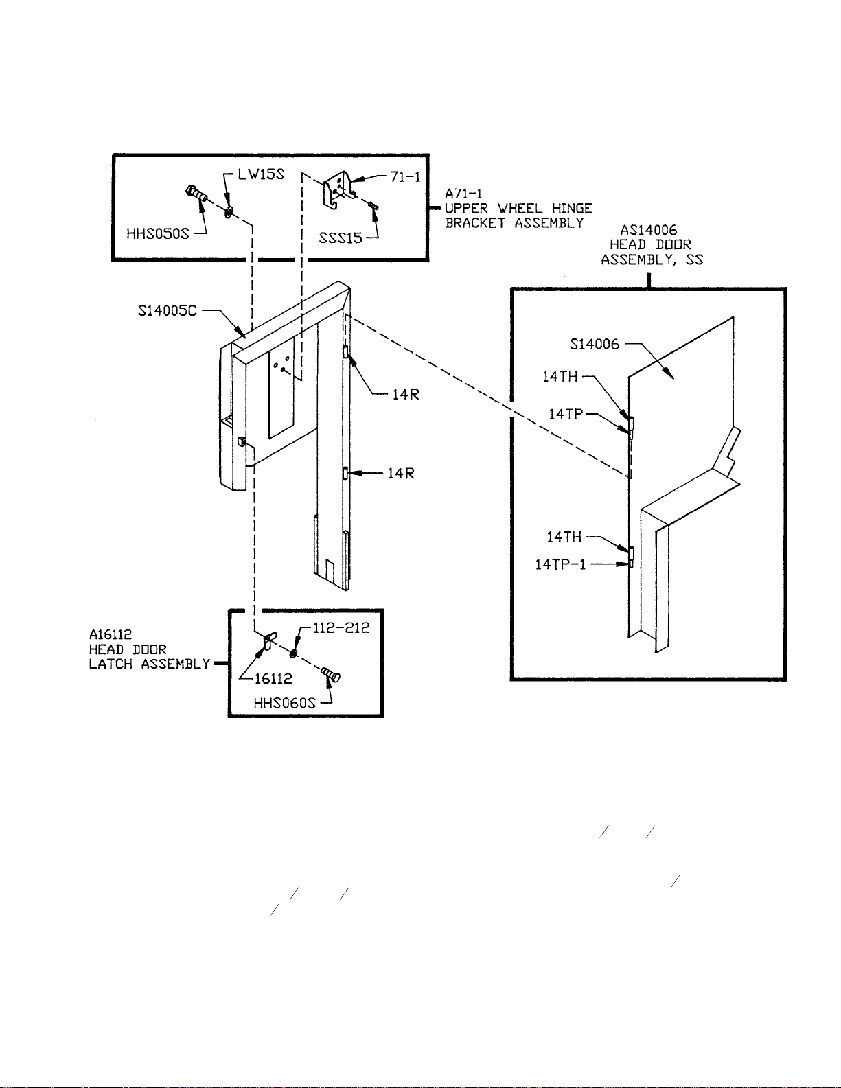
AS14005C
STAINLESS STEEL
HEAD & DOOR ASSEMBLY
15
Item No. Description
A16112 Head door latch assembly
AS14005C Head & door assembly, SS
AS14006 Head door assembly, SS
A71-1 Upper wheel hinge bracket assembly
HHS050S Hex head screw,
5
16
-18
´
5
8
SS
LW15S Lock washer,
5
16
SS
S14005C Head SS
S14006 Head door SS
Item No. Description
SSS15 Set screw,
5
16
-18
´
5
16
cup point
14TH Head door hinge welded
14TP Head door hinge pin, 1½"
14TP-1 Head door hinge pin, 1
1
4
"
14R Head door hinge – welded
112-212 Waved washer
16112 Head door latch
71-1 Upper wheel hinge bracket
17
Page 20

16
Item No. Description
A14003U335-6 Upper wheel assembly w/hinge plate
A14003UDF335-6 Upper wheel assembly – double flange with
hinge plate
A14003U-6 Upper wheel assembly w/o hinge plate
A14003UDF-6 Upper wheel assembly – double flange without
hinge plate
A12335X Upper wheel hinge plate assembly
Item No. Description
A227 Upper bearing cup/cone assembly
A247 Upper shaft bearing assembly
A295 Wheel cleaner assembly
HHS005S Hex head screw, 8-32´½SS
HHS010S Hex head screw, 10-32
´
3
8
SS
HN05S Hex nut, 8-32 SS
HN35S Hex nut,
3
8
-16 SS
S12335X Upper wheel hinge plate
S229 Wheel cleaner arm spring, SS
S244 Wheel cleaner arm stud, SS
S253 Upper wheel aligning screw, SS
S295 Wheel cleaner arm, SS
S325 Wheel cleaner arm stud washer, SS
14003U-6 Upper wheel, 14”, 6 spoke
14003UDF-6 Upper wheel 14”, double flange
179 Wheel cleaner
230DL Upper shaft seal, double lip
234 Grease fitting
237 Upper shaft castellated lock nut
238 Upper shaft castellated lock washer
247 Upper shaft
248 Upper wheel hub cap
252X Upper shaft nut
513 Upper wheel hub gasket
530 Retaining ring (2 req.)
Item No. Description
A16547 Lower bearing housing assembly w/o wheel
A363 Lower bearing cup/cone assembly
HN35S Hex nut,
3
8
-16, SS
LW20S Lock washer,
3
8
,SS
SSS05S Set screw cup, SS, 10-24
´
3
8
14544 Grease seal, 1.50 ID
14545 Retaining ring, internal, 2
7
16
ID
14548 Grease seal,
7
8
ID
14549 Lower bearing housing cap
14550 Adjustment screw, lower bearing housing
14551 Hex jam nut,
5
8
-11, SS
Item No. Description
14560 Lower saw wheel, 14”
14560DF Lower saw wheel 14”, double flange
14740 Retaining ring – external
14746 T-handle lock, removable lower wheel
16251-90X78AL Pulley, upper V-belt 9.0
´
7
8
,AL
16517 Inner race spacer, removable wheel
16543 Shaft, lower saw wheel
16547 Lower bearing housing, removable wheel
280 Key
360A1 Grease fitting angular
360B-1 Set screw ½-13
18
Page 21

17
Item No. Description
A19-1 Ratchet assembly
FW07S Flat washer,
3
8
SS
HHS025S Hex head screw,
1
4
-20
´
1
2
SS
HN15S Hex nut,
1
4
-20 SS
HN35S Hex nut,
3
8
-16 SS
LW10S Lock washer,
1
4
SS
Item No. Description
S11 Ratchet trigger SS
S189 Ratchet arm stud SS
S19 Ratchet base SS
10-1 Ratchet arm
19CB Carriage bolt
1
4
-20
´
3
4
SS
240 Ratchet trigger spring
Item No. Description
AS14273-275 Meat gauge assembly
A14275 Meat gauge plate assembly
A262 Meat gauge release assembly
FW10S Flat washer,
5
16
SS
HHS049NL Hex screw – nylon
5
16
-18´½ lg.
HN20S Hex nut,
5
16
-18 SS
LW10S Lock washer,
1
4
SS
LW15S Lock washer,
5
16
SS
RHS25S Round head screw,
1
4
-20
´
3
4
SS
SSS19 Set screw, cup point,
5
16
-18´1
1
2
,SS
S235 Taper pin, 4
´
3
4
SS
S262 Meat gauge release handle, SS
S265 Meat gauge release spring, SS
S14272 Meat gauge gear rack, SS
Item No. Description
12273LH Meat gauge brkt. — LH
12273RH-3 Meat gauge brkt. — RH
14275 Meat gauge arm
14275-5 Meat gauge plate, SS
264G Meat gauge hand wheel groove pin
264-1 Meat gauge hand wheel
264-1S Hand wheel shim
267 Meat gauge release cotter key
270 Meat gauge release pin
271AL Meat gauge worm gear, Aluminum
272-8 Cap nut,
5
16
-18 SS
272-10 Lock knob
3
8
-16, 4 point
272-11 Allen head cap screw
3
8
-16´1
1
2
lg.
19
Page 22

18
Item No. Description
AS12290 Cleaning unit assembly
AS12290-3 Cleaning unit assembly
A295 Wheel cleaner assembly
HHS003S Hex head screw, 8-32´¼ trimmed SS
HHS005S Hex head screw, 8-32
´
1
2
SS
HHS009S Hex head screw, 10-24´¼SS
HHS055S Hex head screw,
5
16
-18
´
3
4
SS
HN05S Hex nut, 8-32 SS
LW15S Lock washer,
5
16
SS
S12290 Cleaning unit
S12290-3 Cleaning unit
S229 Wheel cleaner arm spring, SS
Item No. Description
S235 Taper, pin, #4
´
3
4
SS
S244 Wheel cleaner arm stud, SS
S295 Wheel cleaner arm, SS
S325 Wheel cleaner arm stud washer, SS
S608 Saw back-up guide w/607 carbide
131 Saw cleaner, SS
131N Blade cleaner, nyleen
131SHORT Blade cleaner, SHORT SS, 1
9
16
LG
131SS/NYL Blade cleaner combo, short, SS, STD Nyleen
179 Wheel cleaner
211Q Lock knob, -18, 4 point
14640 Wheel cleaner, Rulon
Item No. Description
AS116-2214 Saw guide bar assembly 22"
A14211 Finger lift assembly, removable
A602 Saw guide assembly, upper
FW05S Flat washer,
1
4
SS
HHS015S Hex head screw, 10-32
´
7
8
SS
HHS020S Hex head screw,
1
4
-20
´
3
8
SS
HHS083S Hex head screw,
3
8
-16´1
3
4
SS
HN10S Hex nut, 10-32 SS
LW05S Lock washer, #10 SS
LW10S Lock washer,
1
4
SS
RHS10S Round head screw, 10-32
´
3
4
SS
RHS30S Round head screw,
1
4
-20
´
7
8
SS
S200B1 Stop stud on guide bar
S116-22 Saw guide bar, 22", SS
14255 Saw guard
17211-22 Finger lift shim, .022
17211-35 Finger lift shim, .035
193 Saw guide bar spring
211 Finger lift bracket
211A-291Q Fastener knob, 4 point
601 Upper saw guide bracket
602B Upper saw guide with carbide
602AFSC Upper saw guide, narrow, fish
708 Decal “DANGER EXPOSED BLADE”
20
Page 23

19
Item No. Description
AS415D Stationary bar assembly
HHS025S Hex head screw, ¼-20´½SS
LW10S Lock washer, ¼ SS
S268 Stationary bar headless screw
119A Saw guide in stationary bar
177 Nylon filler
S415D Stationary bar
Item No. Description
AS415D-2 Stationary bar assembly
HHS025S Hex head screw, ¼-20´½SS
LW10S Lock washer, ¼ SS
S268 Stationary bar headless screw
119A Saw guide in stationary bar
177 Nylon filler
S415D-2 Stationary bar
S608 Back-up guide, carbide
SSS04S Set screw, 10-24´¼ SS, cup point
Item No. Description
AS12132 Steel cleaner assembly, rear
HHS003S Hex head screw, 8-32
´
1
4
SS
HHS055S Hex head screw,
5
16
-18
´
3
4
SS
LW15S Lock washer,
5
16
SS
S12132 Cleaning unit, rear
S235 Taper pin, #4
´
3
4
SS
131 Blade cleaner, SS
211Q Lock knob,
5
16
-18, 4 point
Item No. Description
A196 Tension spring assembly
HHS040S Hex head screw,
1
4
-20
´
3
4
SS
LW10S Lock washer,
1
4
SS
S118 Tension spring plate
111AL Tension spring pin
197 Tension spring gauge
196 Saw tension spring
198 Tension pin cap
21
Page 24

20
Item No. Description
A16200 Channel stop assembly, movable
A16220-1 Channel stop assembly, fixed
AS16120EZ Channel assembly with center guide
FW08S Flat washer,
3
8
,SS
FW15S Flat washer,
1
2
,SS
HHS055S Hex head screw,
5
16
-18
´
3
4
SS
HHS075S Hex head screw,
3
8
-18´1
1
4
SS
HN25S Hex nut,
3
8
-16, SS
LW15S Lock washer,
5
16
,SS
LW25S Lock washer,
3
8
,SS
S16120 Channel, SS
S200B1 Stop stud, carriage stop, SS
S360CB-1 Carriage bolt,
3
8
-16´1
1
4
,SS
16200 Carriage stop, movable w/#311-1
16220-1 Carriage stop, fixed w/#311
18120EZ-B3 Guide bar, EZ flow, T-shaped
310 Waved washer, movable carriage stop
311 Rubber bumper for #16220-1 stop
311-1 Rubber bumper for #16200 stop
376 Drive screw, #10
´
1
2
lg., SS
Item No. Description
A16155EZ Meat carriage assembly complete – EZ Flow
A175S Thumb guard assembly
FW05S Flat washer, ¼ SS
AN15S Acorn nut, ¼-20, SS
HN30S Hex nut,
3
8
-16 light jam SS
LW20S Lock washer,
3
8
regular SS
S155-11 Meat carriage stop thumb screw
S155-R Raw meat carriage top only (DNS)
S155EZ Meat carriage top only (NSS)
Item No. Description
S155EZ-3 Hex standoff, easy flow carriage
16155EZ Meat carriage top & angle only
16155EZ-1 Meat carriage top only w/weld studs (DNS)
16155-13 Carriage stop angle SS
16155AEZ-1 Meat carriage angle plate
16159 Meat carriage bearing SS
175S Thumb guard, nylon
175-1-S Thumb guard nut, SS
175-2-S Thumb screw, ¼-20´½, SS
22
Page 25

A22616EE-514 BAEG/MS-PB/05-C8 2HP 208-220-50/60-3
A22616EE-516 BAEG/MS-PB/05-E4.7 2HP 440/460-3
A22616EE-518 BAEG/MS-PB/05-D4.7 1.5HP-2HP 380/415-50-3
A22616EE-522 BAEG/MS-PB/05-C14 3HP 220-230-50/60-3
A22616EE-5221 BAEG/MS-PB/05-CS14 1.5HP 220/230-50/60-1
A22616EE-5241 BAEG/MS-PB/A26 1.5HP-2HP 104/115/60-1
A22616EE-5261 BAEG/MS-PB/CS16 2HP 230-60-1
A22616EE-530 BAEG/MS-PB/05-F3.2 2HP 550/575-3
A22616EE-534 BAEG/MS-PB/05-E6.3 3HP 440/460-60-3
A22616EE-536 BAEG/MS-PB/05-D8 3HP 380-60-3
226EE-22PB-GE
OR
226EE-22PB-GF
OR
42MC-Y73
226EE-22PB-RE
OR
42MC-Y74
NOTE
SERIAL NO.
REQUIRED
226EE-ENCL-PB30 ENCLOSURE WITH PUSHBUTTON
30MM HOLES
226EE-OL02.4H OVERLOAD B05-H, 1.7-2.4A
226EE-OL41 OVERLOAD B18K-1, 2.5-4A
H281EE-51 OVERLOAD B18K-K, 4-6.3 A
226EE-OL08.5L OVERLOAD B 18K-L, 5.5-8.5A
23
226EE-OL12M OVERLOAD B18K-M, 8-12A
H281EE-31 OVERLOADB18K-N, 10-16A
226EE-OL26ON OVERL O AD B18K-ON, 21-26A
226EE-AO11K CONT ACT OR, LS11K.11S-A O, 120V
226EE-CO11K CONTA CT OR, LS11K.11S-CO, 208-230V
226EE-EO11K CONTACT OR, LS11K.11S-CO 480V, 60HZ-380V
50HZ
226EE-FO11K CONTACTOR, LS11K.11S-FO, 575V
226EE-22PB-GE ST AR T P/B, 22MM EXT W/NO CONTACT BLK
226EE-22PB-GF STAR T P/B, 22MM FLUSH W/NO CONTACT BLK
226EE-22PB-RE STOP P/B, 22 MM EXT W/NC CONTACT BLOCK
226EE-514 BAEG/MS-PB/05-C8 2HP 220-50/60-3
226EE-516F BAEG/MS-PBF/05-E 4.7 1-1/2, 2HP, 440-60-3
226EE-518 BAEG/MS-PB/05-D4.7 2HP-380-50-3
226EE-5221 BAEG/MS-PSF/05-CS14 1.5HP 230-50/60-1
226EE-5241 BAEG/MS-PB/A26 2HP 120-60-1
226EE-5261 BEAG/MS-PB/CS16 2HP 230-60-1
226EE-530 BAEG/MS-PB/05-F3.2 2HP 550-60-3
226EE-534 BAEG/MS-PB/05-E6.3 3HP 440-60-3
226EE-536 BAEG/MS-PB/05-D8 3HP 380-50-3
226-28 W ASHER, 1-1/2 X 27/32 SS
241BL WIRE, BLACK, 12 GA., CSA & UL
241 GR WIRE, GREEN, 12 GA., CSA & UL
241 RD WIRE, RED, 12 GA., CSA & UL
241 WH WIRE, WHITE, 12 GA., CSA & UL
42MC-Y73 GREEN START BUTT ON
42MC-Y74 RED STOP BUTTON
Page 26

2HP BALDOR MO
TOR: M66-35M388X966-B
2HP BALDOR MO
TOR: M66-35M388S508-B
24
Page 27

25
2HP BALDOR MOTOR: M66-35M388X966-B
2HP
WEG MOTOR: M68-218EP3E145T-W
Page 28

26
2HP BALDOR MOTOR: M68-M3558T-B
2HP US ELECTRIC/EMERSON MO
TOR: M55-G54313-U
3HP US ELECTRIC/EMERSON MOTOR: M701-G57011-U
2HP BALDOR MOTOR: M68-M3558T-50-B
Page 29

27
2HP WEG MOTOR: M68-218EP3E145T-W
2HP BALDOR MO
TOR: M68-M3558T-50-B
Page 30

28
2HP BALDOR MOTOR: M68-M3558T-B
2HP US ELECTRIC/EMERSON MOTOR: M55-G54313-U
3HP US ELECTRIC/EMERSON MOTOR: M701-G57011-U
2HP BALDOR MOTOR: M68-M3558T-50-B
Page 31
WARNING LABEL LOCATIONS ON MACHINE
25
29
Page 32

WEARABLE SAW PARTS THAT WILL FIT BIRO POWER CUTTERS
MODELS
11-22-1433-33-34-3334-44-4436-55
— EXCEPT WHERE NOTED OTHERWISE —
CONTACT YOUR NEAREST BIRO AUTHORIZED DISTRIBUTOR
OR CONTACT BIRO MANUFACTURING
Ph.: 419-798-4451 E.Mail: service@birosaw.com
26
30
Page 33

MODEL 1433 PART NUMBERS AND DESCRIPTIONS
MODEL NO. AND SERIAL NO. REQUIRED
WHEN ORDERING PARTS
27
Item No. Description
HHS049NL Hex screw, nylon,
5
16
-18´½LG
M66-35M388S508-B
Motor, 2HP, 230-50-1 open
M66-35M388X966-B
Motor, 2HP-115/230-60-1 open
M68-67385-D Motor, 2HP, 208/220/440-50/60-3, TE
7
8
S11 Ratchet trigger, SS
S19 Ratchet base, SS
S12132 Cleaning unit, rear
S12290 Front blade, wheel cleaning unit
S12335X Upper wheel hinge plate, SS
S14005C Head, SS
S14006 Head door, SS
S14007 Channel bracket, SS
S14214 Side platter bracket, SS
S14217PD Base door left, SS, bolt on
S14217R Base door right, SS, hinged
S14239 Base, SS
S155-11 Meat carriage stop thumb screw, SS
S155B-1 Meat carriage stop, welded
S155EZ-3 Hex stand off
S16120 Channel
S163F Platter spacer weld button, SS
S189 Ratchet arm stud, SS
S19 Ratchet base
S200B1 Stop stud on saw guide bar
S217C Base door hinge pin, long, SS
S217E Base door hinge pin, short, SS
S229 Wheel cleaner arm torsion spring, SS
S235 Taper pin, SS, 4
´
3
4
S239-B40 Base foot welded, short, SS
S239-B41-4 Adjustable leg bolt, SS
S244 Wheel cleaner arm stud, SS
S253 Upper wheel aligning screw, SS
S262 Meat gauge release handle, SS
S268 Stationary bar headless screw, SS
S295 Wheel cleaner arm, SS
S325 Wheel cleaner arm washer, SS
S360CB-1 Carriaage bolt,
3
8
-16´1
1
4
,SS
S415D-2 Stationary bar, SS
S416 Platter locator weld pin, SS
S608 Lower blade back-up guide w/carbide
10-1 Ratchet arm
111AL Tension spring pin
112-212 Waved washer
S116-22 Saw guide bar, 22"
118 Tension spring plate
119A Saw guide in stationary bar
119FSC Saw guide in stationary bar, fish
12273LH Meat gauge bracket, LH
12273RH-3 Meat gauge bracket, RH
12700-2 Wearable parts replacement kit
131 Saw cleaner, SS
14TP Head door hinge pin, long, 1
1
2
"
Item No. Description
14TP-1 Head door hinge pin, short, 1
1
4
"
14003U-6 Upper wheel, 14"
14003UDF-6 Upper wheel 14" double flange
14212W Platter rod
14232 Scrap bucket
14255 Saw guard on saw guide bar w/708
decal
14256 Junction box
S14272 Meat gauge gear rack, SS
14275 Meat gauge arm
14275-5 Meat gauge plate, SS
14301 Serial number plate (serial no. req’d)
14302HT Saw blade, 108"
14313-266 Operating and service manual
14544 Grease seal, 1.50 ID
14545 Retaining ring, internal, 2
7
16
ID
14548 Grease seal,
7
8
ID
14549 Lower bearing housing cap
14550 Adjustment screw, lower bearing
housing
14551 Hex jam nut,
5
8
-11, SS
14560 Lower saw wheel, removable
14560DF Lower saw wheel 14" double flange
14662 Saw guard, w/708, SS head
14746 T-handle lock, removable lower wheel
150 Conduit, flexible, metal, per inch
151 Conduit, watertight, per inch
16112 Head door latch
16155EZ Meat carriage, EZ flow
16159 Meat carriage bearing
16163B Platter neck guard
16200 Carriage stop, movable
16220-1 Carriage stop, fixed
16251-90X78AL
Upper v-belt pulley 9
´
7
8
, aluminum
163A Platter rod clip
16517 Inner race spacer, removable wheel
16543 Lower shaft
16547 Lower bearing housing, removable
wheel
17211-22 Finger lift shim, .022
17211-35 Finger lift shim, .035
175-1-S Thumb screw,
1
4
D
´
1
2
175-2-S Thumb guard screw
1
4
-20
175S Thumb guard, nylon
177 Stationary bar nylon filler
179 Wheel cleaner
18120EZ-B3 Guide bar, EZ flow, T-shaped
19CB Ratchet base carriage bolt,
3
8
-16´1
3
4
193 Saw guide bar spring
196 Saw tension spring
197 Tension spring gauge
198 Cap, tension spring pin
211 Finger lift bracket
31
Page 34
MODEL 1433 PART NUMBERS AND DESCRIPTIONS (Cont.)
28
Item No. Description
211A-291Q Finger lift fastener knob, 4-point
211D Finger lift fastener bolt
211Q Fastener knob 4 pt.,
5
16
-18
212CP Platter rod cotter pin
221-52 V-belt, 52"
221-53 V-belt, 53"
224 Conduit connector, straight
224-1 Conduit connector, WT, straight
225 Condit connector, 90 degree
225-1 Conduit connector, WT, 90 degree
225-2 Conduit connector, 45 degree
226-28 Conduit connector washer
230DL Upper shaft seal, double lip
231DL Lower shaft seal, double lip
234 Grease fitting, upper wheel
237 Upper shaft castellated lock nut
238 Upper shaft castellated lock nut washer
240 Ratchet trigger spring
242R Base door lock, right
247 Upper shaft
248 Upper wheel hub cap
249 Base door handle
252X Upper shaft lock nut
256P Safety pusher plate, composite
256PM Safety pusher plate, aluminum
259 Conduit anti-short bushing
260 Aluminum slide gib
260ALS Shim for slide gib
264-1 Meat gauge release hand wheel
264G Hand wheel groove pin
Item No. Description
265 Meat gauge release spring
267 Meat gauge release cotter key
270 Meat gauge release pin
271P Meat gauge worm gear, Delrin
272-8 Cap nut
5
16
-18
272-10 Meat gauge lock knob, 4-point
272-11 Lock knob socket screw
280 Key
310 Waved washer
311 Rubber bumper for #16220-1 stop
311-1 Rubber bumper for #16200 stop
324 Motor shim,
1
16
"
324A Motor shim,
1
8
"
331 Platter bracket rubber bumper
340 Star lock washer
360A1 Bearing housing angled grease fitting
374 Shell Cassida grease EPS-2
375 Drive screw for name plate
376 Drive screw, SS, #10
´
1
2
4-30AL Motor pulley, Al, 60 cy, 5
´
3
4
4-35AL Motor pulley, Al, 60 cy, 5
´
7
8
4-45AL Motor pulley, Al, 50 cy, 6
´
3
4
4-49AL Motor pulley, AL, 50 cy, 6
´
7
8
513 Upper wheel hub gasket
530 Retaining snap ring
601 Upper saw guide bracket
602B Saw guide, upper
602AFSC Saw guide, upper, fish
708 Decal “DANGER EXPOSED BLADE”
71-1 Upper wheel hinge bracket
Item No. Description
AS12132 Rear cleaning unit assembly
AS12290 Front cleaning unit assembly
AS14005C Head and door assembly
AS14006 Head door assembly
AS14217R Base door assembly, hinged right
AS16120EZ Channel assembly, EZ flow
AS415D-2 Stationary bar assembly
A116-2214 Saw guide bar assembly
A14003U-6 Upper wheel assembly without hinge
plate
A14003U335-6
Upper wheel assembly with hinge plate
A14163 Stationary platter assembly
A14211 Fingerlift assembly w/guard
AS14273-275 Meat gauge assembly
A14275 Meat gauge plate assembly
Item No. Description
A16112 Head door latch assembly
A16155EZ Meat carriage assembly, EZ flow
A16200 Carriage stop assembly, movable
A16220-1 Carriage stop assembly, fixed
A16547 Lower bearing housing assembly without
wheel
A19-1 Ratchet assembly
A196 Tension spring assembly
A227 Upper bearing cup/cone assembly
A247 Upper shaft bearing assembly without
wheel
A249R Base door lock handle assembly, right
A262 Meat gauge release assembly
A295 Wheel cleaner assembly
A363 Lower bearing cup/cone assembly
A71-1 Upper wheel hinge bracket assembly
32
Page 35

OPERATOR’S SIGNATURE PAGE
WARNING
READ AND UNDERSTAND THIS ENTIRE
MANUAL BEFORE SIGNING BELOW
MY SIGNATURE ATTESTS THAT I HAVE COMPLETELY READ AND UNDERSTAND THIS MANUAL.
I REALIZE THAT THIS MACHINE, IF OPERATED CARELESSLY, CAN CAUSE SERIOUS INJURY TO
MYSELF AND OTHERS.
NAME (PRINT) SIGNATURE
SUPERVISOR’S
INITIALS
DATE
29
33
Page 36

LIMITED WARRANTY:
WARRANTY: The BIRO Manufacturing Company warrants that Model 1433 will be free from defects in material and workmanship under normal use and with recommended service. BIRO will
replace defective parts, which are covered by this limited warranty, provided that the defective
parts are authorized for return, shipping charges prepaid, to a designated factory for inspection
and/or testing.
DURATION OF WARRANTY: The warranty period for all parts covered by this limited warranty is
one (1) year from date of Inspection/Demonstration advised on the returned Warranty Registration
card, or eighteen (18) months from original factory ship date, whichever occurs first, except as
noted below.
PARTS NOT COVERED BY WARRANTY: The following are not covered by this limited warranty:
wearable parts on the cleaning system such as wheel cleaners (Item No. 179), saw blade cleaners
(Item No. 131), blade backup guides (Item No’s. 602B, 605 and 119A), and the nylon filler (Item
No. 177). This limited warranty does not apply to machines sold as used, rebuilt, modified,or altered from the original construction in which the machine was shipped from the factory. (WATER
CONTAMINATED ELECTRICAL SYSTEMS ARE NOT COVERED UNDER THIS LIMITED WARRANTY.) BIRO is not responsible for electrical connection of equipment, adjustments to switch
controls or any other electrical requirements, which must be performed only by a certified electrician. BIRO is not responsible for service charges or labor required to replace any part covered by
this limited warranty or for any damages resulting from misuse, abuse, lack of proper or recommended service.
EXCLUSION OF WARRANTIES AND LIMITATION OF REMEDIES: BIRO gives no warranties
other than those expressly stated in this limited warranty. THE IMPLIED WARRANTY OF MERCHANTABILITY, THE IMPLIED WARRANTY OF FITNESS FOR PROCESSING FOOD PRODUCTS, AND ALL OTHER IMPLIED WARRANTIES ARE SPECIFICALLY EXCLUDED. BIRO IS NOT
LIABLE FOR CONSEQUENTIAL OR INCIDENTAL DAMAGES, EXPENSES, OR LOSSES. THE
REMEDIES PROVIDED IN THIS BIRO LIMITED WARRANTY ARE PURCHASER’S SOLE AND EXCLUSIVE REMEDIES AGAINST BIRO.
REGISTRATION CARDS: You must sign, date and complete the warranty registration card supplied with each machine. The warranty card must be returned to The Biro Manufacturing Company for proper registration. If no warranty card is returned to BIRO, the warranty period will begin
from the date the machine was originally shipped from the factory.
HOW TO GET SERVICE:
1. Contact the agency from whom you purchased the machine; or
2. Consult the yellow pages of the phone directory for the nearest authorized dealer; or
3. Contact Biro Mfg. Company for the nearest authorized service entity (250 plus worldwide) in
your area.
THE BIRO MANUFACTURING COMPANY
1114 Main Street
Marblehead, Ohio 43440-2099
Ph. 419-798-4451
Fax 419-798-9106
E-mail: Service@biro saw.com
Web: http://www.birosaw.com
30
ITEM No.: 14313-266
PTCT: MD 1433-266-12-05-6
ITEM No.: 14313-266
PTCT: MD 1433-266-7-07-7 ACME
34
 Loading...