

Page 1
Instruction Sheet
Wideband Coupler
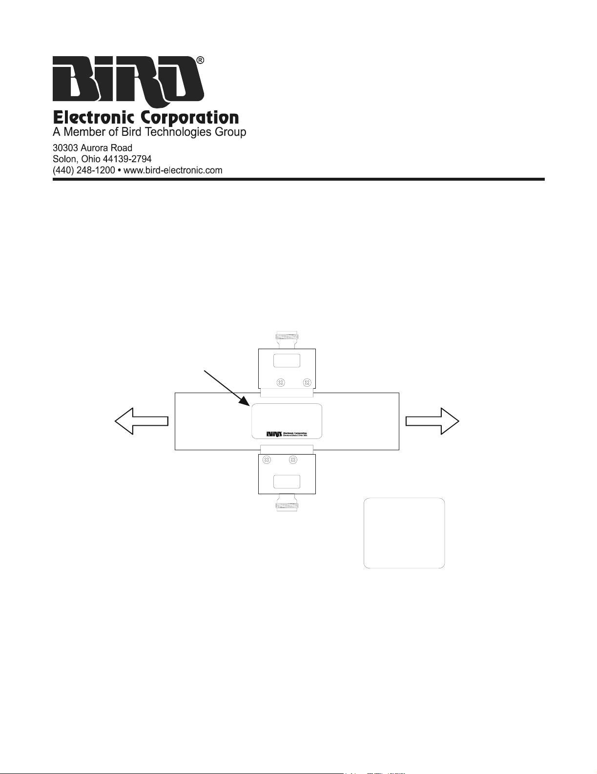
Description
The Bird Wideband Coupler is a short length of line section with two directional couplers, allowing the RF
power in the line to be sampled with the Bird 5011 Terminating Power Sensor (TPS). Couplers are available
for either UHF or VHF operation in a variety of line sizes and power ratings.
To provide accurate power readings, the Wideband Coupler is measured across its frequency band to
determine the exact coupling factors. These are provided on a label on the back of the unit.
FORWARD
COUPLER
TO RF
SOURCE
NAMEPLATE
FWD
WIDEBAND
T
COUPLER
U
P
N
I
RFL
REFLECTED
COUPLER
T
U
P
T
U
O
TO LOAD
OR ANTENNA
COUPLING FACTORS
(ON BACK OF
LINE SECTION)
FREQ
(MHz)
557
563
569
:
:
:
COUPLING
FWD
:
:
63.9543
63.6121
63.6100
:
RFL
:
:
63.9543
63.6121
63.6100
:
920-WBC Rev. A Page 1 of 6
Page 2

Installation
The Bird Wideband Coupler can be inserted directly into the RF line with standard coupling kits.
WARNING
Never attempt to connect or disconnect RF equipment from the
transmission line while RF power is being applied.
Leaking RF energy is a potential health hazard.
CAUTION
Do not remove or switch directional couplers.
Calibration will be voided.
Swivel Flanged Coupling
y Insert the center bullet and push it in until it is fully seated.
y Connect the coaxial input in a straight line and push carefully on the center conductor to close.
NOTE: The swivel flange on the line section makes connection independent of the
orientation of the fixed flange on the RF line.
y Insert the bolt sets and tighten evenly all around to the RF line manufacturer’s recommended torque. Use
all of the bolts.
Unflanged Coupling
y Insert the center bullet and bottom it on the midpoint nibs.
y Position the outer sleeve, with clamping bands, over the line section connector.
y Set the RF line snugly against the coupling stops.
y Position the clamping bands evenly about 3/4” from the ends of the sleeve.
y Tighten the clamping bands.
Operation
NOTE: These instructions are for measuring the transmitted, or forward, power. To
measure reflected power, follow the same instructions but substitute “Reflected” instead
of “Forward” where a direction is specified.
WARNING
Never attempt to connect or disconnect RF equipment from the
transmission line while RF power is being applied.
Leaking RF energy is a potential health hazard.
y Make sure the RF power is off.
y Connect a TPS to the Forward Coupler.
y Connect the TPS to a Bird Digital Power Meter (DPM) or Bird Site Analyzer.
y Look at the coupling factor label on the Wideband Coupler. Note the Forward Coupling Factor at the
operating frequency. Enter this as an offset into the power meter.
NOTE: Refer to the power meter manual for instructions on entering an offset.
y Turn on RF power.
y Measure the power.
Page 2 of 6 Rev. A 920-WBC
Page 3

Customer Service
)
If you need to return the unit for any reason, contact the Bird Service Center for a return authorization. All
instruments returned must be shipped prepaid and to the attention of Bird Service Center.
Bird Service Center
30303 Aurora Road
Cleveland (Solon), OH 44139-2794
Phone: (440) 519-2298
Fax: (440) 519-2326
E-mail: bsc@bird-technologies.com
For the location of the Sales Office nearest you, give us a call or visit our Web site at:
http://www.bird-electronic.com
Dimensions
A
FWD
B
WIDEBAND
T
COUPLER
U
P
N
I
RFL
T
U
P
T
U
O
1.75”
(45 mm
MODEL LINE SECTION DIM. A DIM. B WEIGHT
WBC1 1-
WBC1U 1-
WBC3 3-
WBC3U 3-
WBC3UF 3-
WBC4 4-
WBC4U 4-
WBC6 6-
WBC6U 6-
5
⁄8” Flanged 6.75” (171 mm) 2” (51 mm) 3.7 lbs. (1.7 kg)
5
⁄8” Unflanged 6.38” (163 mm) 1.625” (41 mm) 1.8 lbs. (0.8 kg)
1
⁄8” Flanged 7.03” (179 mm) 5.25” (133 mm) 6.0 lbs. (2.7 kg)
1
⁄8” Unflanged, Recessed
6.5” (165 mm) 3.125” (80 mm) 2.8 lbs. (1.3 kg)
Center Conductor
1
⁄8” Unflanged, Flush
6.5” (165 mm) 3.125” (80 mm) 2.8 lbs. (1.3 kg)
Center Conductor
1
⁄16” Flanged 8.38” (213 mm) 6.2” (158 mm) 8.9 lbs. (4.0 kg)
1
⁄16” Unflanged 7.5” (191 mm) 4.063” (103 mm) 2.9 lbs (1.3 kg)
1
⁄8” Flanged 10.22” (260 mm) 8.375” (213 mm) 13.2 lbs (6.0 kg)
1
⁄8” Unflanged 9.63” (245 mm) 6.125” (156 mm) 7.2 lbs (3.3 kg)
920-WBC Rev. A Page 3 of 6
Page 4

Specifications
Frequency Range
Maximum Power Transmission line and frequency
WBCxx-45
WBCxx-400
WBC6x-400 (6” line section only)
45 – 230 MHz (VHF Band)
450 – 890 MHz (UHF Band)
450 – 800 MHz
dependent. See graph below.
Nominal Coupling
WBC1x
WBC3x
WBC4x
WBC6x
Directivity 28 dB Min.
Coupled Arm Connector Female “N”
Coupled Arm VSWR 1.2 Max
Line VSWR 1.1 Max
Coupling Uncertainty (After Correction) ± 0.05 dB Max
Temperature
Operating
Storage
VHF
62 ± 2 dB
69 ± 2 dB
70 ± 2 dB
75 ± 2 dB
10 to 40 °C (50 to 104 °F)
–20 to +85 °C (–4 to +185 °F)
UHF
59 ± 2 dB
64 ± 2 dB
67 ± 2 dB
72 ± 2 dB
Page 4 of 6 Rev. A 920-WBC
Page 5

Maximum Average Power vs. Frequency
920-WBC Rev. A Page 5 of 6
Page 6

Limited Warranty
All products manufactured by Seller are warranted to be free from defects in material and workmanship for a
period of one (1) year, unless otherwise specified, from date of shipment and to conform to applicable
specifications, drawings, blueprints and/or samples. Seller’s sole obligation under these warranties shall be to
issue credit, repair or replace any item or part thereof which is proved to be other than as warranted; no
allowance shall be made for any labor charges of Buyer for replacement of parts, adjustment or repairs, or
any other work, unless such charges are authorized in advance by Seller.
If Seller’s products are claimed to be defective in material or workmanship or not to conform to specifications,
drawings, blueprints and/or samples, Seller shall, upon prompt notice thereof, either examine the products
where they are located or issue shipping instructions for return to Seller (transportation-charges prepaid by
Buyer). In the event any of our products are proved to be other than as warranted, transportation costs
(cheapest way) to and from Seller’s plant, will be borne by Seller and reimbursement or credit will be made
for amounts so expended by Buyer. Every such claim for breach of these warranties shall be deemed to be
waived by Buyer unless made in writing within ten (10) days from the date of discovery of the defect.
The above warranties shall not extend to any products or parts thereof which have been subjected to any
misuse or neglect, damaged by accident, rendered defective by reason of improper installation or by the
performance of repairs or alterations outside of our plant, and shall not apply to any goods or parts thereof
furnished by Buyer or acquired from others at Buyer’s request and/or to Buyer’s specifications. Routine
(regularly required) calibration is not covered under this limited warranty. In addition, Seller’s warranties do
not extend to the failure of tubes, transistors, fuses and batteries, or to other equipment and parts
manufactured by others except to the extent of the original manufacturer’s warranty to Seller.
The obligations under the foregoing warranties are limited to the precise terms thereof. These warranties
provide exclusive remedies, expressly in lieu of all other remedies including claims for special or
consequential damages. SELLER NEITHER MAKES NOR ASSUMES ANY OTHER WARRANTY WHATSOEVER, WHETHER EXPRESS, STATUTORY, OR IMPLIED, INCLUDING WARRANTIES OF
MERCHANTABILITY AND FITNESS, AND NO PERSON IS AUTHORIZED TO ASSUME FOR SELLER
ANY OBLIGATION OR LIABILITY NOT STRICTLY IN ACCORDANCE WITH THE FOREGOING.
Page 6 of 6 Rev. A 920-WBC
 Loading...