

Page 1

INSTRUCTION BOOK
HIGH POWER
SEMICONDUCTOR
CAL CART
Bird® Electronic Corporation
30303 Aurora Road
Cleveland (Solon), Ohio 44139
Sales & Technical Support: 440-248-1200
Sales email: sales@bird-technologies.com
Technical Support email: atechapp@bird-technologies.com
866-695-4569 toll free
©Copyright 2010 by Bird Electronic Corporation
Instruction Book Part Number 920-HPCC Rev. G
Thruline® and Termaline® are a Registered Trademarks
of Bird Electronic Corporation
Page 2

THIS PAGE INTENTIONALLY LEFT BLANK
Page 3

Safety Precautions
The following are general safety precautions that are not necessarily related to any
specific part or procedure, and do not necessarily appear elsewhere in this publication. These precautions must be thoroughly understood and apply to all phases of
operation and maintenance.
WARNING
Keep Away From Live Circuits
Operating Personnel must at all times observe general safety precautions. Do
not replace components or make adjustments to the inside of the test
equipment with the high voltage supply turned on. To avoid casualties, always
remove power.
WARNING
Shock Hazard
Do not attempt to remove the RF transmission line while RF power is present.
WARNING
Do Not Service Or Adjust Alone
Under no circumstances should any person reach into an enclosure for the
purpose of service or adjustment of equipment except in the presence of
someone who is capable of rendering aid.
WARNING
Safety Earth Ground
An uniterruptible earth safety ground must be supplied from the main power
source to test instruments. Grounding one conductor of a two conductor power
cable is not sufficient protection. Serious injury or death can occur if this
grounding is not properly supplied.
WARNING
Resuscitation
Personnel working with or near high voltages should be familiar with modern
methods of resuscitation.
WARNING
Remove Power
Observe general safety precautions. Do not open the instrument with the power on.
i
Page 4

Bird High Power Semiconductor Cal Cart
Safety Symbols
WARNING
Warning notes call attention to a procedure, which if not correctly performed,
could result in personal injury.
CAUTION
Caution notes call attention to a procedure, which if not correctly performed,
could result in damage to the instrument.
This symbol indicates that a shock hazard exists if the precautions in the instruction manual are not followed.
The caution symbol appears on the equipment indicating there is
important information in the instruction manual regarding that
particular area.
This symbol indicates that the unit radiates heat and should not
be touched while hot.
Note: Calls attention to supplemental information.
Warning Statements
The following safety warnings appear in the text where there is danger to operating and maintenance personnel and are repeated here for emphasis.
WARNING
Do not attempt to lift the cart by the handle.
On page 3.
WARNING
Ethylene glycol is toxic. Do not take internally. Avoid contact with eyes, skin,
and clothing. Avoid breathing vapor. Wash thoroughly after handling.
On page 4.
WARNING
Never attempt to connect or disconnect RF equipment from the transmission line
while RF power is being applied. Leaking RF energy is a potential health hazard.
On pages 6, 12, 16, 17 and 20.
WARNING
To avoid personal injury, disconnect the power cord from the AC line before
performing any maintenance, including fuse replacement.
On pages 11, 16, 17, 18, 20, 21 and 22.
On page 11.
ii
WARNING
The Bird 4421 contains no user-serviceable parts. Do not remove its cover.
Page 5
Caution Statements
The following equipment cautions appear in the text and are repeated here for
emphasis.
CAUTION
Check the electrical code for proper ac hookup prior to operation of the unit.
Make sure the neutral or return hookup is only used for that purpose.
On page 3.
CAUTION
Do not block air flow. The air intake vents on the side of the heat exchanger and
the exhaust on top must not be obstructed.
On page 3.
CAUTION
Use only distilled water or ethylene glycol as coolant. Do not use tap water,
automotive antifreeze, sealants, or leak stopping material. Use of these
materials will damage the instrument and void all warranties.
On pages 4 and 12.
CAUTION
Operation without sufficient coolant will damage the unit.
On pages 4, 7 and 12.
CAUTION
Due to the complexity of the Bird Power Sensor, field repairs beyond general
maintenance should not be attempted. Removal or disturbance of the power
sensor cover can result in cancellation of lifetime warranty.
On pages 13 and 17.
CAUTION
The Bird 4421 must be powered off when connecting or disconnecting the power
sensor from the power meter.
On page 17.
CAUTION
Failure to install a properly rated fuse may result in damage to equipment or
nuisance failure.
On page 18.
iii
Page 6

Bird High Power Semiconductor Cal Cart
Safety Statements
USAGE
ANY USE OF THIS INSTRUMENT IN A MANNER NOT SPECIFIED BY THE
MANUFACTURER MAY IMPAIR THE INSTRUMENT’S SAFETY
PROTECTION.
USO
EL USO DE ESTE INSTRUMENTO DE MANERA NO ESPECIFICADA POR EL
FABRICANTE, PUEDE ANULAR LA PROTECCIÓN DE SEGURIDAD DEL
INSTRUMENTO.
BENUTZUNG
WIRD DAS GERÄT AUF ANDERE WEISE VERWENDET ALS VOM
HERSTELLER BESCHRIEBEN, KANN DIE GERÄTESICHERHEIT
BEEINTRÄCHTIGT WERDEN.
UTILISATION
TOUTE UTILISATION DE CET INSTRUMENT QUI N’EST PAS
EXPLICITEMENT PRÉVUE PAR LE FABRICANT PEUT ENDOMMAGER LE
DISPOSITIF DE PROTECTION DE L’INSTRUMENT.
IMPIEGO
QUALORA QUESTO STRUMENTO VENISSE UTILIZZATO IN MODO
DIVERSO DA COME SPECIFICATO DAL PRODUTTORE LA PROZIONE DI
SICUREZZA POTREBBE VENIRNE COMPROMESSA.
iv
Page 7

SERVICE
SERVICING INSTRUCTIONS ARE FOR USE BY SERVICE - TRAINED
PERSONNEL ONLY. TO AVOID DANGEROUS ELECTRIC SHOCK, DO NOT
PERFORM ANY SERVICING UNLESS QUALIFIED TO DO SO.
SERVICIO
LAS INSTRUCCIONES DE SERVICIO SON PARA USO EXCLUSIVO DEL
PERSONAL DE SERVICIO CAPACITADO. PARA EVITAR EL PELIGRO DE
DESCARGAS ELÉCTRICAS, NO REALICE NINGÚN SERVICIO A MENOS
QUE ESTÉ CAPACITADO PARA HACERIO.
WARTUNG
ANWEISUNGEN FÜR DIE WARTUNG DES GERÄTES GELTEN NUR FÜR
GESCHULTES FACHPERSONAL.
ZUR VERMEIDUNG GEFÄHRLICHE, ELEKTRISCHE SCHOCKS, SIND
WARTUNGSARBEITEN AUSSCHLIEßLICH VON QUALIFIZIERTEM
SERVICEPERSONAL DURCHZUFÜHREN.
ENTRENTIEN
L’EMPLOI DES INSTRUCTIONS D’ENTRETIEN DOIT ÊTRE RÉSERVÉ AU
PERSONNEL FORMÉ AUX OPÉRATIONS D’ENTRETIEN. POUR PRÉVENIR
UN CHOC ÉLECTRIQUE DANGEREUX, NE PAS EFFECTUER D’ENTRETIEN
SI L’ON N’A PAS ÉTÉ QUALIFIÉ POUR CE FAIRE.
ASSISTENZA TECNICA
LE ISTRUZIONI RELATIVE ALL’ASSISTENZA SONO PREVISTE
ESCLUSIVAMENTE PER IL PERSONALE OPPORTUNAMENTE ADDESTRATO.
PER EVITARE PERICOLOSE SCOSSE ELETTRICHE NON EFFETTUARRE
ALCUNA RIPARAZIONE A MENO CHE QUALIFICATI A FARLA.
v
Page 8

Bird High Power Semiconductor Cal Cart
UNITS ARE EQUIPPED WITH RECHAREABLE BATTERIES.
THESE ARE TO BE REPLACED BY AUTHORIZED SERVICE PERSONNEL
ONLY!!!
LAS UNIDADES VIENEN EQUIPADAS CON BATERIAS RECARGABLES.
¡¡¡Y SOLAMENTE EL PERSONAL DE SERVICIO AUTORIZADO PUEDE
REEMPLAZARLAS!!!
GERÄTE SIND MIT WIEDER AUFLADBAREN BATTERIEN BESTÜCKT.
BATTERIEN SIND NUR VON QUALIFIZIERTEM SERICE PERSONAL
AUSZUWECHSELN!!!
CES DISPOSITIFS SONT ÉQUIPÉS DE BATTERIES RECHARGEABLES.
SEUL LE PERSONNEL D’ENTRETIEN AUTORISÉ EST HABILITÉ À LES
REMPLACER !
LE UNITÀ SONO DOTATE DI BATTERIE RICARICABILI,
CHE DEVONO DA COME SPECIFICATO DAL PRODUTTORE LA
PROTEZIONE DI SICUREZZA POTREBBE VENIRNE COMPROMESSA.
vi
Page 9

USE CORRECT VOLTAGE SETTING AND FUSE - SEE MANUAL.
UTILISER UNE TENSION ET UN FUSIBLE CORRECTS - CONSULTER LE MODE
D'EMPLOI.
USE LA INSTALACION Y FUSIBLE DE VOLTAJE CORRECTO - VEA EL MANUAL.
AUSSCHLIESSLICH VORSCHRIFTSMÄSSIGE WECHSELSPANNUNGSEINSTELLUNG UND SICHERUNG BENUTZEN - SIEHE DAZU HANDBUCH.
UTILLIZZARE TENSIONE E FUSIBLE ADATTI - FARE RIFERIMENTO AL
MANUALE.
vii
Page 10

Bird High Power Semiconductor Cal Cart
BE SURE THE 115/230V AC VOLTAGE SELECTOR IS SET TO THE PROPER LINE
VOLTAGE, AND THE CORRECT AC LINE FUSE IS INSTALLED BEFORE AC
POWER IS APPLIED.
S'ASSURER QUE LE SÉLECTEUR DE TENSION 115/230V C.A. EST BIEN RÉGLÉ
POUR LA TENSION DU RÉSEAU ET QUE LE FUSIBLE DE LIGNE C.A. CORRECT
EST EN PLACE AVANT DE METTRE SOUS TENSION C.A.
CERCIORESE QUE EL SELECTOR DE VOLTAJE DE 115/230V CA ESTE
COLOCADO A LA LINEA DE VOLTAJE APROPIADA Y QUE EL FUSIBLE ESTE
INSTALADO A LA LINEA CA ANTES DE APLICAR LA CORRIENTE ALTERNA.
VOR EINSCHALTEN DER WECHSELSTROMZUFUHR SICHERSTELLEN, DASS
DER 115/230V WECHSELSPANNUNGS-SELEKTOR AUF DIE
VORSCHRIFTSMÄSSIGE LEITUNGSSPANNUNG EINGESTELLT UND DIE
RICHTIGE WECHSELSTROM-HAUPTSICHERUNG EINGESETZT IST.
PRIMA DI EROGARE CORRENTE, ASSICURARSI CHE IL SELETTORE DI
VOLTAGGIO 115/230 V.C.A. SIA REGOLATO CORRETTAMENTE E CHE IL
FUSIBLE ADATTO ALLA LINEA DI ALIMENTAZIONE C.A. SIA INSTALLATO.
viii
Page 11
About This Manual
Numbering
This manual covers the operating and maintenance instructions for the following
models:
Cal Cart with 4421 meter, 4028B10M sensor,
8640 load, 1-5/8” flanged connector,
115Vac power supply and standard US plug
SCC81 01 01 01 1
Voltage and
Sensor Load RF Connector
01 4028B10M 01 8640 Series 01 1-5/8” EIA
Flanged
02 8640B Series 2 230V, 30A
Plug Style
1 115V, 15A
Nema 5-15P
Nema L6-30P
3 115V, 10A
International
4 230V, 10A
International
Changes to this Manual
We have made every effort to ensure this manual is accurate. If you discover any
errors, or if you have suggestions for improving this manual, please send your
comments to our Solon, Ohio factory. This manual may be periodically updated.
When inquiring about updates to this manual refer to the part number and revision on the title page.
Terminology
There are some unique terms used throughout this literature. They are defined
here clarify any misunderstanding.
Cal Cart - The entire unit.
Sensor - The power sensor
Meter- The power meter and display
Load - The entire load (water-cooled RF termination).
Resistor Assembly - The load component which connects directly to the RF line.
It is inside the HEAT EXCHANGER, connected by two hoses.
Heat Exchanger - The parts of the Moduload left when the LOAD is removed. It
contains the pump, fans, coolant reservoir, and controls.
Resistor - A subcomponent of the RESISTOR ASSEMBLY. This is the ceramic
resistor which actually absorbs the RF power.
ix
Page 12

Bird High Power Semiconductor Cal Cart
Chapter Layout
Introduction — Describes the features of the Cal Cart, lists equipment supplied
and optional equipment, and provides power-up instructions.
Setup — Describes the power supply and connection instructions.
Operating Instructions — Describes the base level operation instructions.
4421 Instructions — All instructions necessary to operate the 4421 Power Meter
in conjunction with the Bird Semiconductor Cal Cart.
Maintenance — Lists routine maintenance tasks as well as troubleshooting for
common problems. Specifications and parts information are also included.
x
Page 13

Table of Contents
Safety Precautions . . . . . . . . . . . . . . . . . . . . . . . . . . . . . . . . . . . . . . . . . . . . . . . . . . . . . . i
Safety Symbols . . . . . . . . . . . . . . . . . . . . . . . . . . . . . . . . . . . . . . . . . . . . . . . . . . . . . . . . .ii
Warning Statements . . . . . . . . . . . . . . . . . . . . . . . . . . . . . . . . . . . . . . . . . . . . . . . . . . . . . ii
Caution Statements . . . . . . . . . . . . . . . . . . . . . . . . . . . . . . . . . . . . . . . . . . . . . . . . . . . . iii
Safety Statements . . . . . . . . . . . . . . . . . . . . . . . . . . . . . . . . . . . . . . . . . . . . . . . . . . . . . . iv
About This Manual . . . . . . . . . . . . . . . . . . . . . . . . . . . . . . . . . . . . . . . . . . . . . . . . . . . . . ix
Numbering . . . . . . . . . . . . . . . . . . . . . . . . . . . . . . . . . . . . . . . . . . . . . . . . . . . . . . . . . . . ix
Changes to this Manual . . . . . . . . . . . . . . . . . . . . . . . . . . . . . . . . . . . . . . . . . . . . . . . . . ix
Terminology . . . . . . . . . . . . . . . . . . . . . . . . . . . . . . . . . . . . . . . . . . . . . . . . . . . . . . . . . . . ix
Chapter Layout . . . . . . . . . . . . . . . . . . . . . . . . . . . . . . . . . . . . . . . . . . . . . . . . . . . . . . . . .x
Introduction. . . . . . . . . . . . . . . . . . . . . . . . . . . . . . . . . . . . . . . . . . . . . . . . . . . . . . . . . . . . . . 1
Items Supplied . . . . . . . . . . . . . . . . . . . . . . . . . . . . . . . . . . . . . . . . . . . . . . . . . . . . . . . . .1
RF Power Meter . . . . . . . . . . . . . . . . . . . . . . . . . . . . . . . . . . . . . . . . . . . . . . . . . . . . . . . . 1
Power Sensor . . . . . . . . . . . . . . . . . . . . . . . . . . . . . . . . . . . . . . . . . . . . . . . . . . . . . . . . . . . 1
Load . . . . . . . . . . . . . . . . . . . . . . . . . . . . . . . . . . . . . . . . . . . . . . . . . . . . . . . . . . . . . . . . . . 1
Features . . . . . . . . . . . . . . . . . . . . . . . . . . . . . . . . . . . . . . . . . . . . . . . . . . . . . . . . . . . .2
Indicators . . . . . . . . . . . . . . . . . . . . . . . . . . . . . . . . . . . . . . . . . . . . . . . . . . . . . . . . . . .2
Chapter 1 Setup . . . . . . . . . . . . . . . . . . . . . . . . . . . . . . . . . . . . . . . . . . . . . . . . . . . . . . . . 3
Unpacking and Inspection . . . . . . . . . . . . . . . . . . . . . . . . . . . . . . . . . . . . . . . . . . . . . . . . 3
Setup . . . . . . . . . . . . . . . . . . . . . . . . . . . . . . . . . . . . . . . . . . . . . . . . . . . . . . . . . . . . . . . . . 3
Adding Coolant . . . . . . . . . . . . . . . . . . . . . . . . . . . . . . . . . . . . . . . . . . . . . . . . . . . . . . 4
Connecting RF Power . . . . . . . . . . . . . . . . . . . . . . . . . . . . . . . . . . . . . . . . . . . . . . . . . . . . 6
Chapter 2 Operating Instructions . . . . . . . . . . . . . . . . . . . . . . . . . . . . . . . . . . . . . . . . 7
Normal Operation . . . . . . . . . . . . . . . . . . . . . . . . . . . . . . . . . . . . . . . . . . . . . . . . . . . . . . . 7
Shutdown . . . . . . . . . . . . . . . . . . . . . . . . . . . . . . . . . . . . . . . . . . . . . . . . . . . . . . . . . . . . . . 7
Chapter 3 4421 Instructions . . . . . . . . . . . . . . . . . . . . . . . . . . . . . . . . . . . . . . . . . . . . . 9
Audible Warning . . . . . . . . . . . . . . . . . . . . . . . . . . . . . . . . . . . . . . . . . . . . . . . . . . . . . . . 10
Chapter 4 Maintenance . . . . . . . . . . . . . . . . . . . . . . . . . . . . . . . . . . . . . . . . . . . . . . . . 11
Routine Maintenance . . . . . . . . . . . . . . . . . . . . . . . . . . . . . . . . . . . . . . . . . . . . . . . . . . . 11
Inspection . . . . . . . . . . . . . . . . . . . . . . . . . . . . . . . . . . . . . . . . . . . . . . . . . . . . . . . . . . 11
DC Resistance . . . . . . . . . . . . . . . . . . . . . . . . . . . . . . . . . . . . . . . . . . . . . . . . . . . . . . 12
Changing the Coolant . . . . . . . . . . . . . . . . . . . . . . . . . . . . . . . . . . . . . . . . . . . . . . . . 13
Flushing the Coolant . . . . . . . . . . . . . . . . . . . . . . . . . . . . . . . . . . . . . . . . . . . . . . . . . 13
Power Meter and Sensor Troubleshooting . . . . . . . . . . . . . . . . . . . . . . . . . . . . . . . . . . 13
Functional Test . . . . . . . . . . . . . . . . . . . . . . . . . . . . . . . . . . . . . . . . . . . . . . . . . . . . . 14
Push Button Test . . . . . . . . . . . . . . . . . . . . . . . . . . . . . . . . . . . . . . . . . . . . . . . . . . . . 15
Load Troubleshooting . . . . . . . . . . . . . . . . . . . . . . . . . . . . . . . . . . . . . . . . . . . . . . . . . . . 16
Removing the Front Panel . . . . . . . . . . . . . . . . . . . . . . . . . . . . . . . . . . . . . . . . . . . . 17
Replacing the Cord Reel . . . . . . . . . . . . . . . . . . . . . . . . . . . . . . . . . . . . . . . . . . . . . . 17
Replacing the Power Sensor . . . . . . . . . . . . . . . . . . . . . . . . . . . . . . . . . . . . . . . . . . . 17
Replacing Fuses . . . . . . . . . . . . . . . . . . . . . . . . . . . . . . . . . . . . . . . . . . . . . . . . . . . . . 18
Replacing Batteries . . . . . . . . . . . . . . . . . . . . . . . . . . . . . . . . . . . . . . . . . . . . . . . . . . 19
Load Servicing . . . . . . . . . . . . . . . . . . . . . . . . . . . . . . . . . . . . . . . . . . . . . . . . . . . . . . . . .20
xi
Page 14

Replacing Resistor Assembly . . . . . . . . . . . . . . . . . . . . . . . . . . . . . . . . . . . . . . . . . . .20
Removing the Pump . . . . . . . . . . . . . . . . . . . . . . . . . . . . . . . . . . . . . . . . . . . . . . . . . .21
Resistor Assembly . . . . . . . . . . . . . . . . . . . . . . . . . . . . . . . . . . . . . . . . . . . . . . . . . . . . . .22
Removing the Resistor . . . . . . . . . . . . . . . . . . . . . . . . . . . . . . . . . . . . . . . . . . . . . . . . 22
Inspecting the Resistor . . . . . . . . . . . . . . . . . . . . . . . . . . . . . . . . . . . . . . . . . . . . . . . 23
Replacing a Fractured Resistor . . . . . . . . . . . . . . . . . . . . . . . . . . . . . . . . . . . . . . . . .23
Replacing the Resistor . . . . . . . . . . . . . . . . . . . . . . . . . . . . . . . . . . . . . . . . . . . . . . . . 24
Replacing the Conductor . . . . . . . . . . . . . . . . . . . . . . . . . . . . . . . . . . . . . . . . . . . . . .25
Storage and Shipment . . . . . . . . . . . . . . . . . . . . . . . . . . . . . . . . . . . . . . . . . . . . . . . . . . . 25
Storing the Load Resistor . . . . . . . . . . . . . . . . . . . . . . . . . . . . . . . . . . . . . . . . . . . . . 25
Shipping the Load Resistor . . . . . . . . . . . . . . . . . . . . . . . . . . . . . . . . . . . . . . . . . . . . 25
Customer Service . . . . . . . . . . . . . . . . . . . . . . . . . . . . . . . . . . . . . . . . . . . . . . . . . . . . . . .26
Max. Power . . . . . . . . . . . . . . . . . . . . . . . . . . . . . . . . . . . . . . . . . . . . . . . . . . . . . . . . .27
Bird High Power Cal Cart . . . . . . . . . . . . . . . . . . . . . . . . . . . . . . . . . . . . . . . . . . . . .27
Bird 4421 RF Power Meter . . . . . . . . . . . . . . . . . . . . . . . . . . . . . . . . . . . . . . . . . . . .27
Bird 4028B Series RF Power Sensors . . . . . . . . . . . . . . . . . . . . . . . . . . . . . . . . . . . . 28
Bird 8640S Series Moduloads . . . . . . . . . . . . . . . . . . . . . . . . . . . . . . . . . . . . . . . . . . 29
Replacement Parts . . . . . . . . . . . . . . . . . . . . . . . . . . . . . . . . . . . . . . . . . . . . . . . . . . . . .29
Cal Cart . . . . . . . . . . . . . . . . . . . . . . . . . . . . . . . . . . . . . . . . . . . . . . . . . . . . . . . . . . . 29
Resistor Assembly . . . . . . . . . . . . . . . . . . . . . . . . . . . . . . . . . . . . . . . . . . . . . . . . . . .30
Heat Exchanger . . . . . . . . . . . . . . . . . . . . . . . . . . . . . . . . . . . . . . . . . . . . . . . . . . . . . 30
Limited Warranty . . . . . . . . . . . . . . . . . . . . . . . . . . . . . . . . . . . . . . . . . . . . . . . . . . . . . . 33
xii
Page 15

Chapter 1 Introduction
This instruction book is intended for use by operators of the Bird High Power
Cal Cart (HPCC). This chapter contains introductory information including
component descriptions and items supplied.
The HPCC is designed for immediate, effortless use. It has three primary components. The Bird 4421 RF Power Meter displays RF power measurements.
Bird 4028 Series Power Sensors are highly accurate sensors that measure RF
power without requiring calibration or external couplers or attenuators. Bird
Moduloads are low reflection 50 Ω terminations that can dissipate 25 kW.
These components are installed on a cart for easy transportation. The cart is
suitable for use in a cleanroom environment, and is equipped with four swivel
casters for maximum maneuverability. The only setup required is adding coolant and connecting AC and RF power.
Items Supplied
Stainless Steel Cart with the following items installed:
z Bird 4421 RF Power Meter
z Bird 4028 Series Sensor
z Bird 8640 or 8640B Series Moduload
z Cabling
z Instruction Manual
RF Power Meter
Power Sensor
Load
The Bird 4421 RF Power Meter measures forward and reflected RF power
when used with a Bird power sensor. Measurement units can be either Watts
or dBm. Because of the quality of the attached load, reflected power will be
negligible and can usually be ignored.
Note: The 4421 is equipped with rechargeable batteries. These are
shipped uncharged. Connect the unit to AC power the first time you use
it to charge the batteries.
Bird 4028 Series Power Sensors are designed for use in semiconductor processing and calibration applications. 4028 Sensors are accurate to ±2%(2σ) at
specified calibration frequencies and power levels. Sensors are controlled by
the Power Meter.
Bird Moduloads are self-cooling, nonradiating, low reflection terminations for
high power RF lines. They dissipate up to 25 kW with a VSWR of less than
1.1:1 from 1 kHz to 900 MHz.
1
Page 16

Introduction
40"
(1016 mm)
Drain
Plug
Coolant
Gauge
Coolant
Filler Cap
Power
Meter
22"
(559 mm)
39"
(991 mm)
ON/OFF
Switch
Front
Panel
Power Sensor
RF Connector
Handle
Coolant
Reservoir
Pump
Load
Resistor
RF
Input
Fan
To Other Heat
Exchanger Assemblies
Heat Exchanger
Heat Exchanger
Assembly
From Other Heat
Exchanger Assemblies
Features
Indicators
z Useable with CW, AM, FM, SSB, and TV modulation, and certain
pulse types.
Note: Contact Bird Electronic Corporation for information on
using Moduloads with pulsed signals.
z Self-contained water-based cooling system
z Coolant Level Gauge
Figure 1 Cal Cart Outline
2
Figure 2 Load Cooling System Block Diagram
Page 17

Chapter 2 Setup
This chapter provides information for on-site requirements, unpacking,
inspection, and preparing the Bird High Power Cal Cart for use.
Unpacking and Inspection
1. Carefully inspect shipping container for signs of damage.
2. Do one of the following:
z If the shipping container is damaged, do not unpack the unit. Immedi-
ately notify the shipping carrier and Bird Electronic Corporation.
z If the shipping container is not damaged, unpack the unit. Save ship-
ping materials for repackaging.
3. Inspect unit for visual signs of damage.
Note: If there is damage, immediately notify the shipping carrier
and Bird Electronic Corporation.
Setup
Setup consists of three basic steps: moving the unit into position, adding coolant, and connecting AC power and the RF line. These steps are explained in
more detail below.
WARNING
Do not attempt to lift the cart by the handle.
CAUTION
Check the electrical code for proper AC hookup prior to operation of the
unit. Make sure the neutral or return hookup is only used for that purpose.
CAUTION
Do not block air flow. The air intake vents on the side of the heat exchanger
and the exhaust on top must not be obstructed.
z Use the HPCC in a dry, dust-free and vibration-free environment.
Note: Do not use outdoors or in areas of condensing humidity.
z Allow a minimum of one foot clearance along the sides and three feet
over the top to allow unobstructed air intake and exhaust.
z Surrounding air must be free of contaminants or particles that could
be drawn into the air intakes.
z The AC power supply required is 115/230 V @ 50/60 Hz, 1φ.
Note: The unit is equipped with an unterminated, reractable
power cord. Connect a power plug to this cord, appropriate to local
power source.
3
Page 18

Setup
Coolant
WARNING
Ethylene glycol is toxic. Do not take internally.
Avoid contact with eyes, skin, and clothing. Avoid breathing vapor. Wash
thoroughly after handling.
CAUTION
Use only distilled water or a distilled water/ethylene glycol mixture (with a
maximum of 35% ethylene glycol) as coolant. Do not use tap water,
automotive antifreeze, sealants, or leak stopping material. Use of these
materials will damage the instrument and void all warranties.
Distilled water is the primary coolant for the unit. Ethylene glycol can be
added to prevent bacterial growth and freezing; 10% to 35% ethylene glycol is
recommended. Using at least 10% will prevent bacterial growth and at least
35% will prevent freezing to –20°C.
Note: When using both ethylene glycol and distilled water, add the
water first, then the ethylene glycol, to ensure proper mixing.
Adding Coolant
Figure 3 on page 5 shows the coolant’s freezing point for a given percentage of
ethylene glycol in the mix. The following example shows the weights to make a
65% distilled water to 35% ethylene glycol mixture in 5 and 55 gallon quantities.
5 Gal. (18.9 L) 55 Gal. (208.2 L)
Distilled Water 28.0 lb (12.7 kg) 310 lb (140.6 kg)
Ethylene Glycol 15.2 lb (6.9 kg) 167 lb (75.7 kg)
CAUTION
Operation without sufficient coolant will damage the unit.
1. Make sure that the drain plug is in place.
2. Remove the filler cap on the top and at the rear of the unit.
3. Add about 3 quarts (2.9 L) of coolant.
4. Turn the unit on for a few seconds to draw coolant into the system.
5. Repeat steps 3 and 4 twice more, until the coolant remains steady at or
just below the high mark on the level gauge.
6. Replace the filler cap.
7. Turn the unit on
8. Run the unit for five minutes to remove any air trapped in the system.
4
Page 19

Figure 3 Freezing Point of Ethylene Glycol / Distilled Water Mixture
-60
-50
-40
-30
-20
-10
0
Temperature, Degrees Celsius
10 20 30 40 50 60
% Ethylene Glycol
Specifications for ethylene glycol
having: specific gravity 1.125 @
32°F; specific heat .575 @ 68°F
-80
-60
-40
-20
0
20
40
Temperature, Degrees Fahrenheit
10 20 30 40 50 60
% Ethylene Glycol
Specifications for ethylene glycol
having: specific gravity 1.125 @
32°F; specific heat .575 @ 68°F
Setup
5
Page 20

Setup
BOLT BULLET LOADRF COAXIAL LINE
Connecting RF Power
After installing the Bird High Power Cal Cart, the RF transmission line can
be attached using standard coaxial line coupling kits.
To couple the swivel flange with a flanged RF transmission line refer to
Figure 4 while following the instructions below:
Figure 4 Swivel Flanged Coupling
WARNING
Never attempt to connect or disconnect RF equipment from the
transmission line while RF power is being applied.
Leaking RF energy is a potential health hazard.
1. Insert the center bullet and push it in until it is fully seated.
2. Connect the coaxial input in a straight line and push carefully on the center conductor to close.
Note: The swivel flange on the load makes connection independent
of the orientation of the fixed flange on the coaxial input outer conductor.
3. Insert the bolt sets and tighten evenly all around to transmission line
manufacturer’s recommended torque. Use all of the bolts.
6
Page 21

Chapter 3 Operating Instructions
WARNING
Never attempt to connect or disconnect RF equipment from the
transmission line while RF power is being applied.
Leaking RF energy is a potential health hazard.
CAUTION
Operation without sufficient coolant will damage the unit.
Normal Operation
Note: After setting up the Bird High Power Cal Cart:
1. Check that the coolant level is above the minimum mark on the rear coolant gauge.
2. Connect the unit to the AC line.
3. Check that the fans are running properly.
4. Turn on the Bird 4421 power meter.
5. Wait about 10 seconds for proper coolant flow.
6. Apply RF power.
7. Make measurements.
Note: See "Operating Instructions" on page 7 for specific instruc-
tions on controlling the meter.
Shutdown
1. Turn off RF power at the source.
2. Turn off the 4421 power the meter off.
3. Wait approximately 5 minutes for the load to cool to room temperature to
prevent heat stress.
4. Disconnect the AC line.
7
Page 22

Operating Instructions
8
Page 23

Chapter 4 4421 Instructions
LIST EN TALK L OCAL LO CKOUT
FWD
AUTO
LO BAT
REMOTE
MODEL 4421 RF POWER METER
AUTO
RANGE
UP
DOWN
SWRRFLFWD MIN MAX dBm LIGHT ON / OFF
MW nW
KW µW
W mW
dBm
FWD
RFL
SWR
Push Button Functions
Figure 5 Push Buttons
Push Button Description
FWD, RFL
SWR
Press to measure forward (reflected) RF power. FWD (RFL)
indicator and current unit of measure turn on.
Press to measure standing wave ratio. SWR indicator turns on.
Value displayed will be between 1.0 and 199.9
Used after pressing FWD, RFL, SWR, or dBm. Displays the
MIN, MAX
minimum (maximum) measured value of the previous function as
long as MIN (MAX) is held down.
Used after pressing FWD or RFL. dBm indicator turns on. Power is
dBm
displayed in dBm units.
Used after pressing SWR. Return loss is displayed.
LIGHT
Press to turn on or turn off the display’s backlight. If left on, the light
automatically shuts off after 30 minutes.
AUTO Press to automatically set the scale. AUTO turns on.
Press to select the next higher (lower) scale. If the scale is too high
UP, DOWN
for the power sensor, an error will be displayed.
Used while AUTO indicator is on. Stops automatic scaling. AUTO
indicator turns off.
ON/OFF Press to turn the power meter on or off.
9
Page 24

4421 Instructions
Error Codes
The Bird 4421 displays error codes when the RF power is either below the
selected range (underrange) or above the selected range (overrange). Figure 6
displays the error codes and Figure 7 lists the function limits.
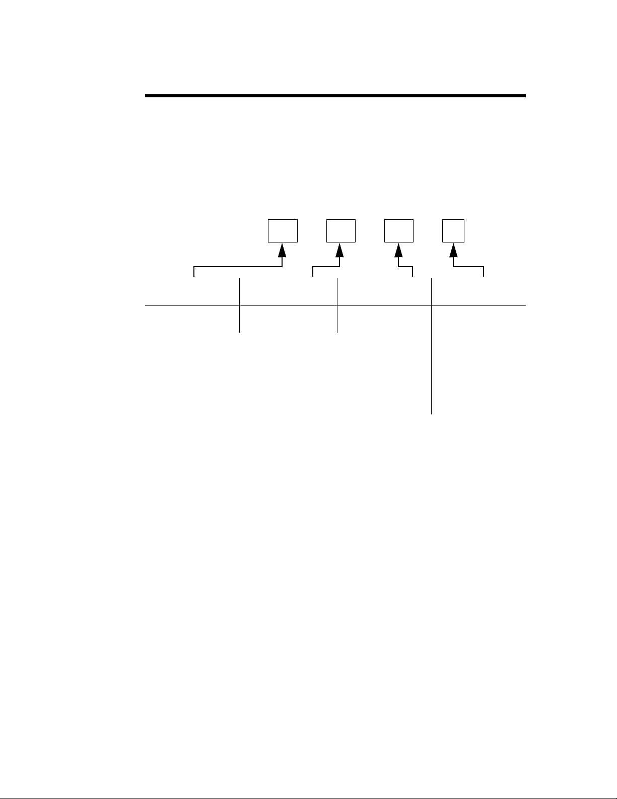
Figure 6 Error Codes
Symbol Explanation
Value greater than overrange limit of function
Value less than underrange limit of function
Figure 7 Function Limits
Function Limit Error
Audible Warning
FWD, RFL
FWD dBm, RFL dBm
SWR
Return Loss
Power > 199.9% of full scale or 120 % of top
range
Power > 120% of full scale
Power < 3% of low range
FWD < 20% of low range
FWD – RFL = 0
FWD < 20% of low range
RFL < 20% of low range
Return Loss > 40 dB
Overrange
Overrange
Underrange
Underrange
Overrange
Underrange
Underrange
Underrange
If the RF power level exceeds 120% of the sensor’s power range, the meter will
sound a warning buzzer.
10
Page 25

Chapter 5 Maintenance
This chapter describes routine maintenance, along with troubleshooting
instructions for the power meter and power sensor. Disassembly instructions
for the Bird High Power Cal Cart are also provided. For service beyond this
level, return the unit to a qualified service center.
WARNING
To avoid personal injury, disconnect the power cord from the AC line before
performing any maintenance, including fuse replacement.
WARNING
Never attempt to connect or disconnect RF equipment from the
transmission line while RF power is being applied.
Leaking RF energy is a potential health hazard.
WARNING
The Bird 4421 contains no user-serviceable parts.
Do not remove its cover.
This manual cannot list all malfunctions that may occur, or corrective actions.
If a malfunction is not listed or is not corrected by the listed corrective actions,
contact a qualified service center.
Routine Maintenance
Inspection
The HPCC requires only simple, routine maintenance.
z Wipe off dust and dirt regularly.
z Check the connectors and cables for damage.
z Clean the connector contacts with alcohol or dry cleaning solvent.
z If dust has collected on the radiator coils, remove the screws around
the edge of the top panel, remove the panel, and vacuum the coils.
z The coolant level should be checked once a week, more often if the Cal
Cart is used continuously or in high ambient temperatures.
Note: The coolant level should be above the minimum mark on the
gauge even when the unit is on. To add coolant, See “Changing the
Coolant” on page 13.
11
Page 26

Maintenance
DC Resistance
Measuring the DC resistance between the inner and outer conductors of the
RF connector shows changes in the load over time, a good check of the resistor’s condition. Under normal operating conditions, the resistor should provide
at least 5,000 hours of operation before requiring any additional service. DC
resistance tracking must start before the load is put into service, and should
be measured annually.
Perform the following steps and record the value for future comparison. Make
sure that you have an ohmmeter with an accuracy of ±1% at 50 ohms and that
the load temperature is between 20 and 25 °C (68 to 77 °F) before starting.
Figure 8 Measuring Resistance
WARNING
Never attempt to connect or disconnect RF equipment from the
transmission line while RF power is being applied.
Leaking RF energy is a potential health hazard.
1. Turn off the RF power.
2. Disconnect the RF cables from the RF connectors on the load.
3. Check the load’s center and outer conductors for visible damage or excessive wear.
4. Connect the multimeter test leads to the center and outer conductors.
Refer to Figure 8.
5. Compare the measured value with the previous measurement and with
the baseline resistance, measured when the load was put into service.
Note: If the new value differs from either of these by more than 2
ohms this could indicate a failing resistor.
WARNING
Ethylene glycol is toxic. Do not take internally. Avoid contact with eyes, skin,
and clothing. Avoid breathing vapor. Wash thoroughly after handling.
CAUTION
Use only distilled water or the supplied mixture of distilled water and
ethylene glycol (with a maximum of 35% ethylene glycol) as coolant. Do not
use tap water, automotive antifreeze, sealants, or leak stopping material.
Use of these materials will damage the instrument and void all warranties.
12
CAUTION
Operation without sufficient coolant can damage the unit.
Page 27

Changing the Coolant
Maintenance
Note: To just add coolant, go to step 5. To just drain the coolant,
follow steps 1 – 4.
1. Get a clean container, with a capacity of 3 gal. (11 L), to hold the old coolant.
2. Remove the filler cap on the top and at the rear of the unit.
Note: This will allow the coolant to drain faster.
3. Unscrew and remove the drain plug at the bottom rear.
4. Drain the coolant into the container.
Note: If the coolant has no contaminants it may be reused.
5. Replace the drain plug and screw it tightly into place.
6. Add about 3 quarts (2.9 L) of coolant.
7. Turn the unit on for a few seconds to draw coolant into the system.
8. Repeat steps 6 and 7 twice more, until the coolant remains steady at or
just below the high mark on the level gauge.
9. Replace the filler cap.
10. Turn the unit on and run it for five minutes to remove any air trapped in
the system.
Flushing the Coolant
Note: If the coolant is contaminated, for example by pipe sealant
or a broken resistor, the system should be thoroughly flushed.
1. Fill the unit with clean, potable water.
2. Run the unit for five minutes with no RF power applied.
3. Drain the coolant and discard it.
4. Repeat steps 1 – 3 until the drained liquid is clear.
5. Refill the system with proper coolant (distilled water or a distilled water/
ethylene glycol mixture) as described above.
Power Meter and Sensor Troubleshooting
Since the power meter and power sensor can only work together, the first step
is to determine which is malfunctioning. Connect the power sensor to the
meter and perform the functional test on page 14. If the power meter is malfunctioning, refer to the troubleshooting table below. If the power sensor is
malfunctioning, return it for service.
Due to the complexity of the Bird Power Sensor, field repairs beyond
general maintenance should not be attempted. Removal or disturbance of
the power sensor cover can result in cancellation of lifetime warranty.
CAUTION
13
Page 28

Maintenance
Meter’s
Model
Number
Meter’s
Software
Rev. Date
Sensor’s
Model
Number
Sensor’s
Software
Rev. Date
–..4421..–07.01.02–..4021..–07.01.02–
PROBLEM POSSIBLE CAUSE CORRECTION
Power meter has no
power
Dash moves across
the display
Display blank or not
updating
Power meter turns off
while on battery power
Push buttons do not
respond
Every segment on the
display is lit
Have the batteries been
Recharge the batteries.
charged?
Is the power meter’s AC power
Connect the power cord.
cord connected to the terminal
strip?
Is the Cal Cart’s AC power cord
Connect AC power.
connected to the AC line?
Is the ON/OFF rocker switch on
Set the switch to ON.
the rear panel set to OFF?
Unplug the Cal Cart. Has the
power meter fuse blown?
Replace fuse (See “Replacing
Fuses” on page 18).
Is the AC power cord defective? Replace AC power cord.
Is the sensor cable connected
Connect sensor cable.
to both the power meter and
power sensor?
Is the sensor cable defective? Replace sensor cable.
Have the batteries been
charged?
NO: Recharge battery
YES: Return meter for service.
Is “LO BAT” displayed? YES: Recharge battery
NO: Return meter for service.
Test the push buttons (See
Return meter for service.
“Push Button Test” on page 15).
Are they defective?
Return meter for service.
Functional Test
1. Disconnect the AC power cable and turn the power meter off.
Note: The On/Off switch on the rear panel of the meter should be On.
2. Connect the AC power cable.
3. Press the On/Off button on the front panel of the power meter whileholding down the FWD and SWR push buttons, .
4. Immediately release all three.
5. Ensure that both of following happen:
z The power meter’s model number and revision date should scroll
across the display.
Note: If a dash “–” is displayed instead, then the meter is malfunc-
tioning.
z The power sensor’s model number and revision date should scroll
across the display.
Note: If a dash “–” is displayed after the power meter data, then
the power sensor is malfunctioning.
Figure 9 Test Display, No Malfunction
14
Page 29

Push Button Test
Maintenance
Note: This test checks that the push buttons and display are function-
ing properly. If a push button is malfunctioning, return the power meter.
1. Disconnect the power sensor.
2. Turn the power meter On.
Note: After the power up display disappears, three dashes “– – –”
should scroll across the display.
3. “AUTO” and “FWD” should be displayed, and a reading of “.000 W”.
4. Press RFL. “FWD” should change to “RFL” on the display.
Note: The reading should remain the same.
5. Press SWR.
Note: “RFL” should change to “SWR”. “.000 W” should change to
“ ” (underrange error).
6. Hold down MIN.
Note: “ ” should change to “ ” (overrange error).
7. Release MIN.
Note: “ ” should change to “ ”.
8. Hold down MAX.
Note: “ ” should change to “.000”.
9. Release MAX.
Note: “.000” should change to “ ”.
10. Press dBm.
Note: “SWR” should change to “dBm”.
11. Press dBm.
Note: “dBm” should change to “SWR”.
12. Press FWD.
Note: “SWR” should change to “FWD”. “ ” should change
to “.000 W”.
13. Press LIGHT.
Note: The back-light should turn on.
14. Press LIGHT.
Note: The back-light should turn off.
15. Press s (up).
Note: The power meter should change ranges each time it is
pressed until it reaches “.000 KW”.
16. Press t (down).
Note: The power meter should change ranges each time it is
pressed until it reaches “.000 W”.
17. Turn the power meter OFF.
15
Page 30

Maintenance
40"
(1016 mm)
Drain
Plug
Coolant
Gauge
Coolant
Filler Cap
Power
Meter
22"
(559 mm)
39"
(991 mm)
ON/OFF
Switch
Front
Panel
Power Sensor
RF Connector
Handle
Load Troubleshooting
PROBLEM POSSIBLE CAUSE CORRECTION
Repair
Blower not
operating
Is the load’s AC power cord
connected to the terminal strip?
Is the Cal Cart’s AC power cord
Connect the power cord.
Connect AC power.
connected to the AC line?
Unit turned off. Set the line switch to ON.
Fuse burnout. Replace fuse (See "Replacing
Fuses" on page 18).
Coolant leaking Loose connections. Tighten drain plug and all
connections.
Worn or cracked tubing. Replace defective tubing.
Excessive
reflected power
Resistor’s DC resistance has
changed.
Check DC resistance. See "DC
Resistance" on page 12).
Figure 10 Cal Cart Outline
16
WARNING
To avoid personal injury, disconnect the power cord from the AC line before
performing any maintenance, including fuse replacement.
WARNING
Never attempt to connect or disconnect RF equipment from the
transmission line while RF power is being applied.
Leaking RF energy is a potential health hazard.
Page 31

Removing the Front Panel
1. Remove the screws on the front panel.
2. Pull on the handle set into the base of the front panel to remove it.
3. When making AC connections, refer to the wiring diagram below.
Figure 11 Cal Cart Wiring Schematic
Replacing the Cord Reel
Maintenance
Note: To access the power sensor or the AC connections, it will be
necessary to remove the cart’s front panel.
1. Disconnect the cord reel from the terminal strip.
2. Unscrew the AC connector.
3. Unscrew and remove the cord reel.
4. Screw the replacement cord reel into place.
5. Replace the ring terminal and quick disconnects on the cord reel.
6. Thread the AC connector through the grommet, and connect the wires on
the other end to the terminal strip (See Figure 11).
Replacing the Power Sensor
To avoid personal injury, disconnect the power cord from the AC line before
The Bird 4421 must be powered off when connecting or disconnecting the
WARNING
performing any maintenance, including fuse replacement.
WARNING
Never attempt to connect or disconnect RF equipment from the
transmission line while RF power is being applied.
Leaking RF energy is a potential health hazard.
CAUTION
power sensor from the power meter.
CAUTION
Due to the complexity of the Bird Power Sensor, field repairs beyond
general maintenance should not be attempted.
Removal or disturbance of the power sensor cover can result in cancellation
of lifetime warranty.
17
Page 32

Maintenance
Fuse 1
Fuse 2
Fuse
Drawer
AC Module
Replacing Fuses
1. Disconnect the RF line from the HPCC.
2. Remove the unit’s front panel (see "Removing the Front Panel" on
page 17).
3. Disconnect the sensor cable from the power sensor.
4. Disconnect the RF cable from the sensor output port.
5. Remove the screws on the sensor mounting bracket and remove the sensor
from the mounting bracket.
6. Put the new sensor in the bracket and screw it into place.
Note: Make sure the arrow on the side of the sensor points towards
the load, and that the end labeled “SOURCE” points towards the front
of the Cal Cart.
7. Connect the RF cable to the sensor end labeled “LOAD”.
8. Connect the sensor cable.
9. Replace the unit’s front panel.
WARNING
To avoid personal injury, disconnect the power cord from the AC line before
performing any maintenance, including fuse replacement.
CAUTION
Failure to install the properly rated fuse may result in equipment damage
or nuisance failures.
1. Gently pry the fuse drawer out of the AC module.
Note: The fuse holder does not detach from the AC module.
2. Install the replacement fuses then close and secure the fuse holder.
Fuse 1 is a spare fuse and fuse 2 is the active fuse.
AC Line Voltage Fuse Rating
115 Vac T630 mA, 5x20 mm Time Lag Fuse
230 Vac T315 mA, 5x20 mm Time Lag Fuse
Figure 12 AC Line Fuse
18
Page 33

Replacing Batteries
X4
X4
Maintenance
WARNING
Exposed AC line voltage (115 VAC or 230 VAC). Disconnect the power cord
from the AC line before replacing the batteries. Failure to comply may
result in severe electrical shock or death.
1. Disconnect the AC power cord from the AC mains supply.
2. Remove the four screws that secure the top cover.
3. Lift the top cover to access the attached ground wire then disconnect the
ground wire and remove the cover.
4. Unfasten the battery retaining belts then remove the battery tubes (Figure 13).
Note: Be sure to note the polarity and orientation of the battery
tubes before removing them.
5. Remove the batteries from each tube and insert replacement batteries.
Note: Be sure to note the polarity (positive and negative) arrange-
ment of the batteries.
6. Install the battery tubes into the unit and secure with the retaining belts.
Note: Be sure to position the retaining belts as they were before
removal and tighten them securely.
7. Connect the ground wire to the top cover.
8. Install the top cover.
9. Secure the top cover with the four screws removed earlier.
Figure 13 Batteries
Item Description
1 Battery retaining belt
2 Battery tube (batteries inside)
19
Page 34

Maintenance
Load Servicing
Replacing Resistor Assembly
To avoid personal injury, disconnect the power cord from the AC line before
1. Disconnect the RF line from the Cal Cart
2. Disconnect the Sensor from the Load.
3. Remove the Cal Cart front panel (see "Removing the Front Panel" on page 17).
4. Disconnect the load’s AC line from the terminal strip.
5. Drain the coolant (See “Changing the Coolant” on page 13).
6. Remove the screws around the edge of the top panel
7. Raise the top panel only high enough to gain access to the fan supply plug.
8. Disconnect the fan-supply plug on top of the radiator block by pressing the
latch in the center of the plug while pulling away from the mating connector.
9. Unscrew the hose clamps on both water connections to the resistor assembly.
10. Remove the nuts, on the inside of the front panel, holding the assembly to
the front panel.
11. Unscrew the mounting clamp holding the resistor assembly to the rest of
the unit.
12. Remove the top half of the clamp.
13. Carefully push the assembly forward a few inches to access the wires and
water connection fittings.
14. Note the position and direction of the output elbow then unscrew it from
the load.
15. The resistor assembly can now be removed.
WARNING
performing any maintenance, including fuse replacement.
WARNING
Never attempt to connect or disconnect RF equipment from the
transmission line while RF power is being applied.
Leaking RF energy is a potential health hazard.
Note: Remove the nuts only. Do not disturb the screws. The screws
also secure the outer conductor assembly to the resistor. Hold this
assembly to keep it from falling and being damaged.
20
Page 35

Removing the Pump
Maintenance
WARNING
To avoid personal injury, disconnect the power cord from the AC line before
performing any maintenance, including fuse replacement.
1. Drain the coolant (See “Changing the Coolant” on page 13).
2. Remove the load (See “Replacing Resistor Assembly” on page 20).
3. Disconnect the pump wire leads from the terminal block on the inside of
the front panel.
4. Loosen the hose clamps on the input and output hoses to the pump, and
remove the hoses.
5. Unscrew the hex nut on the drain tube at the base of the pump. Remove
the drain tube.
6. Unscrew the bolts securing the base of the pump to the unit.
7. Remove the pump, carefully, from the unit.
8. Note the position and direction of the fittings, then twist them off counterclockwise.
9. To replace the pump, reverse the above steps.
Note: When replacing the threaded fittings, carefully coat the
external threads, ONLY, with a pipe sealing compound. Coating only
the external threads reduces the chances of contaminating the coolant.
21
Page 36

Maintenance
Resistor
Outer Flow Tube
1
9A
Resistor Sleeve
7
Load Housing
O-Ring
8
Inner Flow Tube
9
Ground Cap Assembly
10
Hose Fitting 90°
5
Hose Fitting 90°
5
Inner O-Ring
17
Outer O-Ring
2
Water Chamber With
O-Ring Inner Seal
3
and
4
1/4-20 x 2-1/2
Socket Head Cap Screw (6)
6
Load Housing
Resistor
Center Conductor
Assembly
1/4-20 x 1-1/2
Socket Head Cap Screw (6)
Outer Conductor
Assembly
Resistor Fitting Seal O-Ring
12
16
11
1
15
Resistor Assembly
The load is designed to be quickly and easily repaired in the field. If a significant change in the DC resistance is noted or if the resistor should fail, inexpensive replacement resistors are available.
WARNING
To avoid personal injury, disconnect the power cord from the AC line before
performing any maintenance, including fuse replacement.
Figure 14 Load Exploded View
Removing the Resistor
22
Note: Numbers in brackets [ ] refer to the labeled parts in Figure 14.
1. Remove the resistor assembly. (see "Replacing Resistor Assembly" on
page 20).
2. Turn the assembly on end with the hose fitting up.
Note: Use a
approximately
3. Pull the water chamber assembly out.
Note: It may be necessary to rock the chamber gently while pulling.
3
⁄16 hex socket wrench to tighten the cap screws [6]
1
⁄2 inch-lbs.
Page 37

Inspecting the Resistor
Maintenance
4. Remove the following parts and set them aside for reassembly:
z Inner flow tube [9]
z Resistor sleeve [7]
z Cushioning O-ring [8]
5. Remove the ground cap assembly by gently prying it upward using the flat
blade of a screw driver and working around the circumference of the part
until is is free.
Note: The ground cap assembly [10] should now be exposed on the
resistor at the end of the load housing.
6. Pull the resistor [1] straight out using a gentle rocking motion.
Note: Do this only if the resistor [1] is intact.
Note: The resistor sleeve [7] has a small escape hole at the side and
an access counter bore leading to it. If the sleeve is removed, be sure
this counterbore faces the O-Ring and the resistor [1] during reassembly. This is essential for internal water venting. The base of the inner
flow tube has water outlet holes and a small shoulder. At reassembly,
these must fit into mating recesses in the input fitting.
1. Carefully check the resistor [1] for fractures.
2. Check the inside of the housing for damage to the internal parts.
3. Do one of the following:
z If the resistor is broken, other internal parts are damaged, or if the
z If no damage has been found, proceed to "Replacing the Resistor" on
Replacing a Fractured Resistor
1. Turn the assembly on end with the RF input connector up to allow any
loose pieces of the resistor to fall out of the housing.
2. Use a
3. Remove the outer conductor assembly [12].
4. Pull out the center conductor assembly [11].
5. Remove, carefully, any remaining pieces of the resistor.
6. Check the inside of the housing for damage.
7. Remove the inner flow tube [9] and ground cap assembly [10].
8. Check inner flow tube and ground cap assembly for broken pieces.
9. Wash, thoroughly, the inside of the conductor assemblies, housing and
water chamber under clear running water.
10. Replace the ground cap assembly and the inner flow tube.
Note: Even in the event of failure the resistor substrate will usu-
ally remain intact.
parts do not fit together properly, proceed to "Replacing a Fractured
Resistor" on page 23.
page 24.
3
⁄16 hex socket wrench to remove the cap screws [16].
Note: Normally the outer flow tube will remain with the housing.
If it comes out, return it after inspection and cleaning.
23
Page 38

Maintenance
Replacing the Resistor
1. Insert the new resistor [1] into the resistor fitting of the center conductor
assembly [15] to test its tightness.
Note: The resistor should be snug but should not have to be forced
into the fitting. If the resistor is too loose:
a. Press the fitting fingers together slightly
b. Insert the resistor again.
c. Continue closing the ends of the resistor fitting until a snug fit
is obtained.
2. Bottom the resistor in the fitting.
3. Insert the resistor and center conductor assembly into the housing.
4. Replace the outer conductor assembly [12] and screw it into place.
5. Stand the load on its end with the RF connector down.
6. Replace the ground cap assembly onto the exposed end of the resistor.
Note: Make sue that it seats on the load housing.
7. Do one of the following:
z If the inner flow tube [9] is separated from the water chamber assembly [3]:
a. Place it inside the resistor
b. Lower until it reaches the resistor fitting.
c. Twist, gently, the flow tube until it seats in the bottom of the resis-
tor fitting.
z If the inner flow tube [9] is not separated from the water chamber
assembly [3], procedd to Step 4.
4. Check that the O-Ring [8] is on the inner flow tube next to the resistor and
the resistor sleeve [7] is right behind it.
Note: Make sure the counterbore faces the O-Ring and the resistor.
5. Replace the water chamber [3], gently rocking and twisting the chamber
to achieve a flat seat on the outer housing.
Note: If the water chamber does not fit properly make sure that the
inner flow tube is properly placed.
6. Tighten the water chamber screws [6].
7. Check the DC resistance between the inner and outer conductors; it
should be about 50 ohms.
Note: Record this measurement as the new baseline reading.
8. Install the resistor assembly on the heat exchanger.
9. Connect the hoses and fill with coolant.
10. Run the pump for five minutes and check for leaks before applying RF
power.
24
Page 39

Replacing the Conductor
1. Remove the cap screws [16] from the RF connector, using a
2. Remove the outer conductor assembly [12].
3. Remove the center conductor assembly [11] by pulling it carefully out of
4. Insert the new center conductor assembly into load housing.
5. Replace the outer conductor and screw it into place.
Storage and Shipment
Storing the Load Resistor
1. Cover Bird HPCC Loads before storing to keep out dust and dirt.
2. It is not necessary to install the shipping plug.
3. Store in a dry, dust-free environment where the ambient temperature will
Maintenance
3
⁄16 allen wrench.
Note: If only the outer conductor needs replaced, install it now and
screw it into place.
the load housing.
Note: Make sure the resistor [1] and inner flow tube [9] do not
come out with the center conductor.
Note: Make sure the resistor fitting makes a snug fit with the resistor.
remain between –40 and +45 °C (–40 to +113 °F).
Shipping the Load Resistor
1. Remove the vent plug.
2. Install the shipping plug.
3. Wrap the vent plug with padding and tape it to the side of the load for pro-
4. Wrap the connector in padding.
5. Pack and brace the load in a sturdy wooden crate for shipment.
tection.
Note: With the shipping plug installed, it is not necessary to empty
out the coolant.
25
Page 40

Maintenance
Customer Service
Any maintenance or service procedure beyond the scope of those in this chapter should be referred to a qualified service center.
If you need to return the unit for any reason, request an RMA through the
Bird Technologies website (link shown below). All instruments returned must
be shipped prepaid and to the attention of the RMA number.
Bird Service Center
30303 Aurora Road
Cleveland (Solon), Ohio 44139-2794
Fax: (440) 248-5426
E-mail: bsc@bird-technologies.com
For the location of the Sales Office nearest you, visit our website at:
http://www.bird-technologies.com
26
Page 41

Specifications
Max. Power
Maintenance
To determine the model numbers of the Cal Cart components, see “Numbering”
on page ix.
Note: Certain sensors or connectors may be incompatible with some
models. See “Numbering” on page ix for a list of available components,
or contact Customer Service.
The Cal Cart’s maximum power is the MINIMUM of the max. power of the
sensor and the max. power of the load, under normal conditions.
Bird High Power Cal Cart
Frequency Range Sensor dependent
Power Range Dependent on sensor, sensor connectors, and load
Connectors 1-5/8” Flanged
Dimensions 40”L x 22”W x 39”H (1005 x 550 x 991 mm)
Weight, Nominal 240 lbs. (109 kg)
Tempe rature Load coolant dependent
Calibration Cycle 1 year
Bird 4421 RF Power Meter
VSWR Display 1.0 – 199.9 max
Return Loss Display 0 to 40 dB max
Display Accuracy ± 1 on least significant digit
AC Power 115/230 Vac @ 50/ 60 Hz
Batteries 8 Nickel Metal Hydride rechargeable 1.2 volt cells
Battery Life Approximately 8 hours continuous usage
Battery Charger Built-in battery charger. Drained batteries require
approximately 28 hours to recharge.
Display LCD, 4½ digit display. Indicates mode, measurement units,
battery condition, remote status, and signal increase /
decrease. Self contained backlight.
Fuse Rating
115 Vac
230 Vac
Dimensions, Nominal 15.5”L x 12.25”W x 4.25”H (393 x 311 x 108 mm)
Weight, Nominal 9.5 lbs. (4.3 kg)
IEC (5 x 20 mm) Time Lag Type T
T630 ma
T315 ma
27
Page 42

Maintenance
RFL Accuracy FWD Accuracy
FWD Power
10
Directivity 10/
---------------------------------+=
VSWR 1
P
R
P
F
------+
⎝⎠
⎜⎟
⎛⎞
1
P
R
P
F
------–
⎝⎠
⎜⎟
⎛⎞
⁄=
Bird 4028B Series RF Power Sensors
Frequency Range
4028B10M 10 – 15 MHz
RF Power Range 1 kW – 25 kW
Accuracy, Fwd, Best Case
*
Accuracy, Reflected Calculated from FWD accuracy and FWD power
Accuracy, VSWR Calculated from FWD and RFL power
± 2.0% (2σ)
Calibration Frequencies,
Typical (MHz)
4028B10M
†
10.0, 13.56, 15.0
Calibration Power, Typical 3.5 kW
VSWR, Max. 1.05:1
Insertion Loss, Max. 0.05 dB
Directivity, Min. 28 dB
Impedance, Nominal 50 ohms
VSWR Range 1.00 to 2.00 (40.0 to 9.5 dB Return Loss)
Max. Allowable Terminating
2.00:1
VSWR
Calibration Technique Calibration vs. frequency curve stored in nonvolatile
memory in each sensor. Sensor output corrected at
frequency of measurement within rated range.
Sampling Rate, Nominal 2 readings / second
Operating Power Supplied by power meter via sensor cable
Dimensions, Nominal 6.75”L x 3.5”W x 4.75”H (175 x 89 x 121 mm)
Weight, Nominal 5 lb. 2 oz. (2.33 kg)
* For rated accuracy, no more than 1% AM; Harmonics –50 dBc or less
Derate accuracy by 2% (2σ) outside cal. power or cal. frequency
Derate accuracy by 2% (2
σ) below 15 °C and above 35 °C
† Other calibration frequencies available upon request
28
Page 43

Maintenance
Bird 8640S Series Moduloads
Frequency Range 1 kHz – 900 MHz
Power Rating 25 kW continuous duty
Mode CW, AM, FM, SSB, TV and certain pulse types
Impedance, Nominal 50 ohms
VSWR, Max 1.10:1
Cooling Method Water dielectric and forced air convection
Coolant
Coolant Capacity 9 qts. (8.5 L) nominal
AC Power 115/230 Vac @ 50/ 60 Hz
Fuse Rating
Operating Temperature
*
115 Vac
230 Vac
Water only
35% Ethylene Glycol
Distilled water or distilled water/ethylene glycol
mixture
15 A (3AB time delay)
8 A (5x20 mm time delay)
†
†
5 to 45
0 to 35
°C (41 to 113 °F)
†
°C (32 to 95 °F)
Replacement Parts
Cal Cart
Storage Temperature
Water only
35% E.G.
* Below 5°C, ONLY use 35% E.G. and 65% Dist. H2O mixture
† Above 30°C (86 °F) with water only, or 25°C (77 °F) with a 35% ethylene gly-
col mixture, derate power to 20 kW max.
+5 to +50 °C (41 to 122 °F)
–20 to +50 °C (–4 to +122 °F)
Description Qty Part Number
Power Meter Fuse,
IEC (5 x 20 mm) Type T
115 Vac, T630 mA
230 Vac, T315 mA
Cord, AC Power, Power Meter
115 Va c
230 Vac Harmonized
Plug, 115 Vac 1 5A2626
Cable, Sensor 1 4421-038
Grommet 1 SA2617-20
Cordreel 1 4421A383-2
Handle 1 4421A385
1
5A2257-14
5A2257-11
1
5-1286
5A2416
29
Page 44

Maintenance
Resistor Assembly
Exploded views are used to illustrate the parts below and indicate their relation to each other. Each part in the exploded view has an item number referencing this list.
Item No. Description Qty Part Number
1 Resistor 1 8755-027
2 Outer O-Ring 1 8410-009
3 Water Chamber 1 8755-014
4 Water Chamber Inner O-Ring 1 5-099
5 Fitting, 90° 2 8640-089
6 Screw
1
⁄
-20 x 2-
4
7 Resistor Sleeve 1 8755-026
8 Sleeve O-Ring 1 8110-059
9 Inner Flow Tube 1 8755-025
1
⁄
” 6 1121-2508-00
2
Heat Exchanger
9A Outer Flow Tube 1 8755-024
10 Resistor Ground Cap 1 8755-005
15 Center Conductor O-Ring 1 5-1127
16 Screw
1
⁄
4
-20 x 1
1
⁄
” 6 1121-1808-00
2
17 Inner O-Ring 1 5-567
Description Qty Part Number
Cord, AC Power
115 Vac
230 Vac
Fuse
115 Vac, 15 A (3AB time delay)
230 Vac, 8 A (5x20 mm time delay
Coolant Gauge Kit 1 5-1200
Ethylene Glycol 1 Gal. 5-1134-3
1
5-1836
5-1837
2
5-1828-36
5A2257-25
30
Page 45

Figure 15 Resistor Assembly Exploded View
Resistor
Outer Flow Tube
1
9A
Resistor Sleeve
7
Load Housing
O-Ring
8
Inner Flow Tube
9
Ground Cap Assembly
10
Hose Fitting 90°
5
Hose Fitting 90°
5
Inner O-Ring
17
Outer O-Ring
2
Water Chamber With
O-Ring Inner Seal
3
and
4
1/4-20 x 2-1/2
Socket Head Cap Screw (6)
6
Load Housing
Resistor
Center Conductor
Assembly
1/4-20 x 1-1/2
Socket Head Cap Screw (6)
Outer Conductor
Assembly
Resistor Fitting Seal O-Ring
12
16
11
1
15
Maintenance
31
Page 46

Maintenance
Replacement Parts
Casters 4 4421A384
Battery, size C, NiMH 8 5A1230
Cable, IEEE-488
2 m
1 m
Description Qty Part Number
1
5-1317-2
5-1317-1
Cable, RS-232
10 ft.
5 ft.
Null Modem Kit (RS-232 only) 1 4380-250
Panel Mount Kit 1 4421-250
1
5-1662-2
5-1662-1
32
Page 47

Limited Warranty
All products manufactured by Seller are warranted to be free from defects in material and workmanship for a
period of one year, unless otherwise specified, from date of shipment and to conform to applicable specifications,
drawings, blueprints and/or samples. Seller’s sole obligation under these warranties shall be to issue credit, repair
or replace any item or part thereof which is proved to be other than as warranted; no allowance shall be made for
any labor charges of Buyer for replacement of parts, adjustment or repairs, or any other work, unless such
charges are authorized in advance by Seller.
If Seller’s products are claimed to be defective in material or workmanship or not to conform to specifications, drawings, blueprints and/or samples, Seller shall, upon prompt notice thereof, either examine the products where they are located or issue shipping instructions for return to Seller
(transportation charges prepaid by Buyer). In the event any of our products are proved to be other
than as warranted, transportation costs (cheapest way) to and from Seller’s plant, will be borne by
Seller and reimbursement or credit will be made for amounts so expended by Buyer. Every such claim
for breach of these warranties shall be deemed to be waived by Buyer unless made in writing within
ten days from the date of discovery of the defect.
The above warranties shall not extend to any products or parts thereof which have been subjected to
any misuse or neglect, damaged by accident, rendered defective by reason of improper installation or
by the performance of repairs or alterations outside of our plant, and shall not apply to any goods or
parts thereof furnished by Buyer or acquired from others at Buyer’s request and/or to Buyer’s specifications. Routine (regularly required) calibration is not covered under this limited warranty. In addition, Seller’s warranties do not extend to the failure of tubes, transistors, fuses and batteries, or to
other equipment and parts manufactured by others except to the extent of the original manufacturer’s
warranty to Seller.
The obligations under the foregoing warranties are limited to the precise terms thereof. These warranties
provide exclusive remedies, expressly in lieu of all other remedies including claims for special or consequential damages. SELLER NEITHER MAKES NOR ASSUMES ANY OTHER WARRANTY WHATSOEVER,
WHETHER EXPRESS, STATUTORY, OR IMPLIED, INCLUDING WARRANTIES OF MERCHANTABILITY AND FITNESS, AND NO PERSON IS AUTHORIZED TO ASSUME FOR SELLER ANY OBLIGATION OR LIABILITY NOT STRICTLY IN ACCORDANCE WITH THE FOREGOING.
Special Lifetime Warranty - Series 4020, Series 4027A,
Series 4027F, and Series 4028 Power Sensor Head
In addition to its standard warranty, the Bird Electronic Corporation warrants its Series 4020, Series
4027A, Series 4027F, and Series 4028 Thruline® Power Sensor Heads for lifetime to original purchaser. This extended warranty is against burnout. For the warranty to apply, the Sensor Head must
be used with the correct Bird Electronic Corporation Display Unit, the maximum power rating of the
Sensor must not be exceeded, the Sensor RF circuit must be properly terminated and the Sensor not
subjected to physical abuse.
Bird Electronic Corporation, at its option, will repair or replace the defective Sensor at its world
Headquarters at 30303 Aurora Road, Solon, Ohio 44139.
The customer is responsible to pay transportation charges to return the defective sensor to Bird.
 Loading...