

Page 1

INSTRUCTION BOOK
MULTI-SENSOR
CAL CART
SYSTEM
Bird® Electronic Corporation
30303 Aurora Road
Cleveland (Solon), Ohio 44139
Sales & Technical Support:440-248-1200
866-695-4569 toll free
Sales email:sales@bird-technologies.com
Technical Support email:atechapp@bird-technologies.com
©Copyright 2010 by Bird Electronic Corporation
Instruction Book Part Number 920-MSCC Rev. F
Thruline® and Termaline® are a Registered Trademarks
of Bird Electronic Corporation
Page 2

THIS PAGE INTENTIONALLY LEFT BLANK
Page 3

Safety Precautions
The following are general safety precautions that are not necessarily related to any
specific part or procedure, and do not necessarily appear elsewhere in this publication. These precautions must be thoroughly understood and apply to all phases of
operation and maintenance.
WARNING
Keep Away From Live Circuits
Operating Personnel must at all times observe general safety precautions. Do
not replace components or make adjustments to the inside of the test equipment
with the high voltage supply turned on. To avoid casualties, always remove
power.
WARNING
Shock Hazard
Do not attempt to remove the RF transmission line while RF power is present.
Capacitors can store a dangerous electrical charge. Avoid contact with all system
capacitors. If it is necessary to perform work near a system capacitor, be sure to
discharge the capacitor through a low resistance.
WARNING
Do Not Service Or Adjust Alone
Under no circumstances should any person reach into an enclosure for the
purpose of service or adjustment of equipment except in the presence of
someone who is capable of rendering aid.
WARNING
Safety Earth Ground
An uniterruptible earth safety ground must be supplied from the main power
source to test instruments. Grounding one conductor of a two conductor power
cable is not sufficient protection. Serious injury or death can occur if this
grounding is not properly supplied.
WARNING
Resuscitation
Personnel working with or near high voltages should be familiar with modern
methods of resuscitation.
WARNING
Remove Power
Observe general safety precautions. Do not open the instrument with the power
on.
i
Page 4
Bird Multi-Sensor Cal Cart System
Safety Symbols
WARNING
Warning notes call attention to a procedure, which if not correctly performed
could result in personal injury.
CAUTION
Caution notes call attention to a procedure, which if not correctly performed
could result in damage to the instrument.
The caution symbol appears on the equipment indicating there is
important information in the instruction manual regarding that
particular area.
Note: Calls attention to supplemental information.
Warning Statements
The following safety warnings appear in the text where there is danger to operating and maintenance personnel and are repeated here for emphasis.
WARNING
Refer to the supplied load manual for load-specific warnings and cautions.
On pages 2 and 5.
WARNING
All vent plugs must be installed on the load at all times when the unit is
operating or cooling. Failure to do so could result in an explosion or severe burns.
On page 3.
WARNING
Do not attempt to lift the cart by the handle.
On page 3.
WARNING
Never attempt to connect or disconnect RF equipment from the transmission line
while RF power is being applied. Leaking RF energy is a potential health hazard.
On pages 3, 5, 9, and 12.
WARNING
RF Safety Cover provides protection against RF power. Do not defeat this
safety device.
On page 4.
WARNING
To avoid personal injury, disconnect the power cord from the AC line before
performing any maintenance, including fuse replacement.
On pages 9 and 12.
On page 13.
ii
WARNING
Heavy load. Do not attempt to lift unaided.
Page 5

Caution Statements
The following equipment cautions appear in the text whenever the equipment is
in danger of damage and are repeated here for emphasis.
CAUTION
The Bird 4421 contains no user-serviceable parts. Do not remove its cover.
On pages 9.
CAUTION
The Bird 4421 must be powered off when connecting or disconnecting the power
sensor from the power meter.
On pages 12.
CAUTION
Due to the complexity of the Bird Power Sensor, field repairs beyond general
maintenance should not be attempted. Removal or disturbance of the power
sensor cover can result in cancellation of lifetime warranty.
On pages 9 and 12.
CAUTION
Changing the sensor’s connectors will invalidate calibration data, and may
reduce the maximum power rating of the unit.
On pages 1, 3, 12, 16, 17, and 19.
CAUTION
Check the local electrical code for proper AC hookup prior to operation of the
unit. Make sure the neutral or return hookup is only used for that purpose.
On pages 3.
CAUTION
Use the Bird Cal Cart in a dry, dust and vibration free environment. Do not use
outdoors or in areas of condensing humidity. Allow at least 12" (30 cm) of
clearance around the load.
On page 4.
CAUTION
Maximum power dissipation is severely reduced when the blower is not running.
If the indicator light should turn off, immediately reduce RF power by 75%.
On page 5.
iii
Page 6

Bird Multi-Sensor Cal Cart System
Safety Statements
USAGE
ANY USE OF THIS INSTRUMENT IN A MANNER NOT SPECIFIED BY THE
MANUFACTURER MAY IMPAIR THE INSTRUMENT’S SAFETY
PROTECTION.
USO
EL USO DE ESTE INSTRUMENTO DE MANERA NO ESPECIFICADA POR EL
FABRICANTE, PUEDE ANULAR LA PROTECCIÓN DE SEGURIDAD DEL
INSTRUMENTO.
BENUTZUNG
WIRD DAS GERÄT AUF ANDERE WEISE VERWENDET ALS VOM
HERSTELLER BESCHRIEBEN, KANN DIE GERÄTESICHERHEIT
BEEINTRÄCHTIGT WERDEN.
UTILISATION
TOUTE UTILISATION DE CET INSTRUMENT QUI N’EST PAS
EXPLICITEMENT PRÉVUE PAR LE FABRICANT PEUT ENDOMMAGER LE
DISPOSITIF DE PROTECTION DE L’INSTRUMENT.
IMPIEGO
QUALORA QUESTO STRUMENTO VENISSE UTILIZZATO IN MODO
DIVERSO DA COME SPECIFICATO DAL PRODUTTORE LA PROZIONE DI
SICUREZZA POTREBBE VENIRNE COMPROMESSA.
iv
Page 7

SERVICE
SERVICING INSTRUCTIONS ARE FOR USE BY SERVICE - TRAINED
PERSONNEL ONLY. TO AVOID DANGEROUS ELECTRIC SHOCK, DO NOT
PERFORM ANY SERVICING UNLESS QUALIFIED TO DO SO.
SERVICIO
LAS INSTRUCCIONES DE SERVICIO SON PARA USO EXCLUSIVO DEL
PERSONAL DE SERVICIO CAPACITADO. PARA EVITAR EL PELIGRO DE
DESCARGAS ELÉCTRICAS, NO REALICE NINGÚN SERVICIO A MENOS
QUE ESTÉ CAPACITADO PARA HACERIO.
WARTUNG
ANWEISUNGEN FÜR DIE WARTUNG DES GERÄTES GELTEN NUR FÜR
GESCHULTES FACHPERSONAL.
ZUR VERMEIDUNG GEFÄHRLICHE, ELEKTRISCHE SCHOCKS, SIND
WARTUNGSARBEITEN AUSSCHLIEßLICH VON QUALIFIZIERTEM
SERVICEPERSONAL DURCHZUFÜHREN.
ENTRENTIEN
L’EMPLOI DES INSTRUCTIONS D’ENTRETIEN DOIT ÊTRE RÉSERVÉ AU
PERSONNEL FORMÉ AUX OPÉRATIONS D’ENTRETIEN. POUR PRÉVENIR
UN CHOC ÉLECTRIQUE DANGEREUX, NE PAS EFFECTUER D’ENTRETIEN
SI L’ON N’A PAS ÉTÉ QUALIFIÉ POUR CE FAIRE.
ASSISTENZA TECNICA
LE ISTRUZIONI RELATIVE ALL’ASSISTENZA SONO PREVISTE
ESCLUSIVAMENTE PER IL PERSONALE OPPORTUNAMENTE
ADDESTRATO. PER EVITARE PERICOLOSE SCOSSE ELETTRICHE NON
EFFETTUARRE ALCUNA RIPARAZIONE A MENO CHE QUALIFICATI A
FARLA.
v
Page 8

Bird Multi-Sensor Cal Cart System
UNITS ARE EQUIPPED WITH RECHAREABLE BATTERIES.
THESE ARE TO BE REPLACED BY AUTHORIZED SERVICE PERSONNEL
ONLY!!!
LAS UNIDADES VIENEN EQUIPADAS CON BATERIAS RECARGABLES.
¡¡¡Y SOLAMENTE EL PERSONAL DE SERVICIO AUTORIZADO PUEDE
REEMPLAZARLAS!!!
GERÄTE SIND MIT WIEDER AUFLADBAREN BATTERIEN BESTÜCKT.
BATTERIEN SIND NUR VON QUALIFIZIERTEM SERICE PERSONAL
AUSZUWECHSELN!!!
CES DISPOSITIFS SONT ÉQUIPÉS DE BATTERIES RECHARGEABLES.
SEUL LE PERSONNEL D’ENTRETIEN AUTORISÉ EST HABILITÉ À LES
REMPLACER !
LE UNITÀ SONO DOTATE DI BATTERIE RICARICABILI,
CHE DEVONO DA COME SPECIFICATO DAL PRODUTTORE LA
PROTEZIONE DI SICUREZZA POTREBBE VENIRNE COMPROMESSA.
vi
Page 9

USE CORRECT VOLTAGE SETTING AND FUSE - SEE MANUAL.
UTILISER UNE TENSION ET UN FUSIBLE CORRECTS - CONSULTER LE MODE
D'EMPLOI.
USE LA INSTALACION Y FUSIBLE DE VOLTAJE CORRECTO - VEA EL MANUAL.
AUSSCHLIESSLICH VORSCHRIFTSMÄSSIGE WECHSELSPANNUNGSEINSTELLUNG UND SICHERUNG BENUTZEN - SIEHE DAZU HANDBUCH.
UTILLIZZARE TENSIONE E FUSIBLE ADATTI - FARE RIFERIMENTO AL
MANUALE.
vii
Page 10

Bird Multi-Sensor Cal Cart System
BE SURE THE 115/230V AC VOLTAGE SELECTOR IS SET TO THE PROPER LINE
VOLTAGE, AND THE CORRECT AC LINE FUSE IS INSTALLED BEFORE AC
POWER IS APPLIED.
S'ASSURER QUE LE SÉLECTEUR DE TENSION 115/230V C.A. EST BIEN RÉGLÉ
POUR LA TENSION DU RÉSEAU ET QUE LE FUSIBLE DE LIGNE C.A. CORRECT
EST EN PLACE AVANT DE METTRE SOUS TENSION C.A.
CERCIORESE QUE EL SELECTOR DE VOLTAJE DE 115/230V CA ESTE
COLOCADO A LA LINEA DE VOLTAJE APROPIADA Y QUE EL FUSIBLE ESTE
INSTALADO A LA LINEA CA ANTES DE APLICAR LA CORRIENTE ALTERNA.
VOR EINSCHALTEN DER WECHSELSTROMZUFUHR SICHERSTELLEN, DASS
DER 115/230V WECHSELSPANNUNGS-SELEKTOR AUF DIE
VORSCHRIFTSMÄSSIGE LEITUNGSSPANNUNG EINGESTELLT UND DIE
RICHTIGE WECHSELSTROM-HAUPTSICHERUNG EINGESETZT IST.
PRIMA DI EROGARE CORRENTE, ASSICURARSI CHE IL SELETTORE DI
VOLTAGGIO 115/230 V.C.A. SIA REGOLATO CORRETTAMENTE E CHE IL
FUSIBLE ADATTO ALLA LINEA DI ALIMENTAZIONE C.A. SIA INSTALLATO.
viii
Page 11
About This Manual
This manual covers the operating & maintenance instructions for the following models:
Sample Model MSCC7117180101011
Cal Cart with 4421 meter, 4027F2M sensor, 4027F10M sensor,
8921A100 load, two female N connectors,
115Vac power supply and standard US plug
MSCC71 17 18 01 01 01 1
Sensor 1
&
Sensor 2 Load
01 4027A10M 01 8921A100 01 N (F) 1 115V, 15A
02 4027A250K 02 8931A400-115 02 7-16 DIN 2 230V, 30A
03 4027A400K 03 8931A400-230 03 LC (F) 3 115V, 10A
04 4027A800K 04 HN (F) 4 230V, 10A
05 4027A2M 05 TRU 6934 F
06 4027A4M 06 TRU 7958 F
07 4027A12M 07 4240-025
08 4027A25M 08 4240-063
11 4021
13 4024
14 4025
Connector 1
&
Connector 2
09 4240-363
Voltage and
Plug Style
Nema 5-15P
Nema L6-30P
International
International
17 4027F10M
18 4027F2M
Changes to this Manual
We have made every effort to ensure this manual is accurate. If you discover any
errors, or if you have suggestions for improving this manual, please send your
comments to our Solon, Ohio factory. This manual may be periodically updated.
When inquiring about updates to this manual refer to the part number and revision on the title page.
ix
Page 12

Bird Multi-Sensor Cal Cart System
Contents
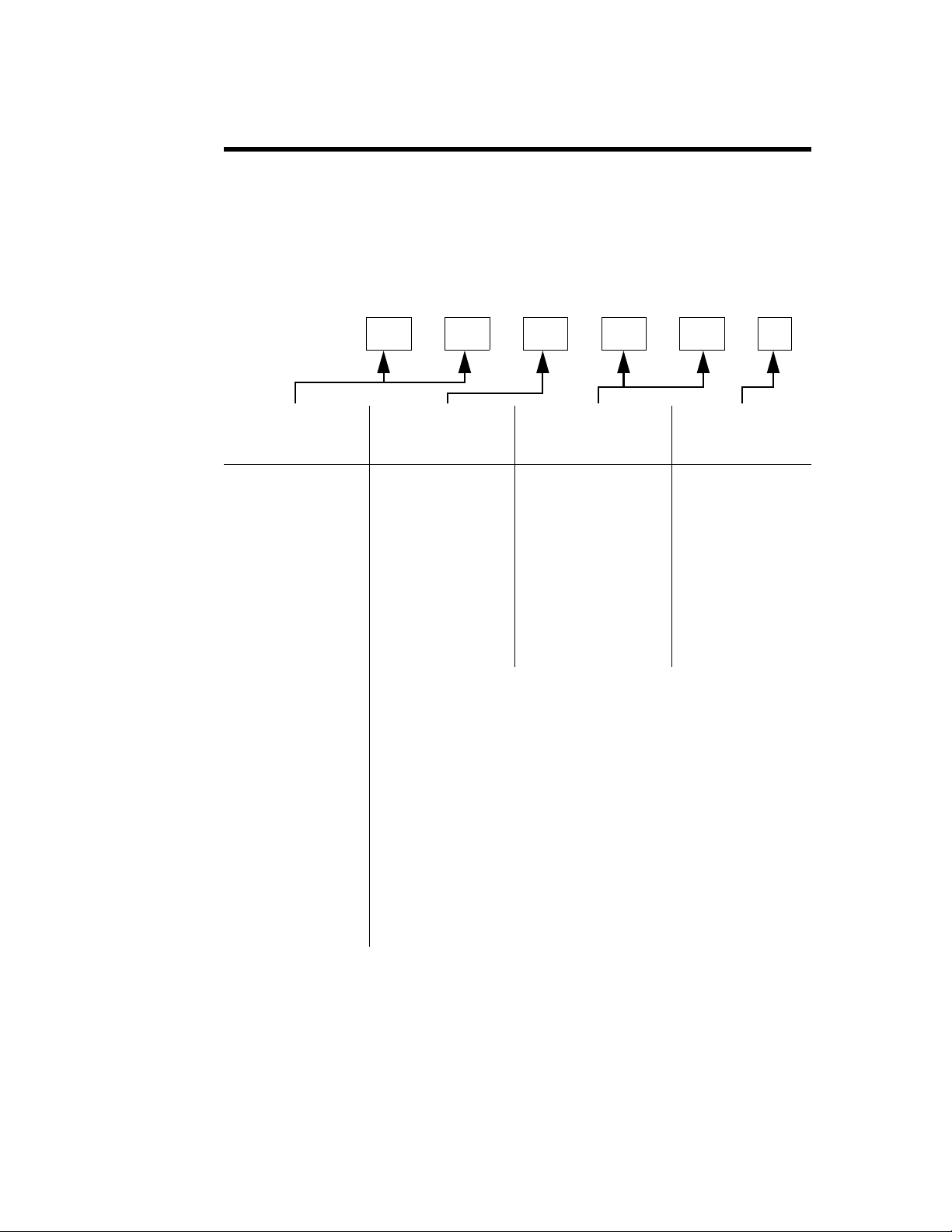
Chapter Layout
Introduction Installation Operating Instructions Maintenance -
x
Page 13

Table of Contents
Safety Precautions . . . . . . . . . . . . . . . . . . . . . . . . . . . . . . . . . . . . . . . . . . . . . . . . . . . . . . i
Safety Symbols . . . . . . . . . . . . . . . . . . . . . . . . . . . . . . . . . . . . . . . . . . . . . . . . . . . . . . . . .ii
Warning Statements . . . . . . . . . . . . . . . . . . . . . . . . . . . . . . . . . . . . . . . . . . . . . . . . . . . . . ii
Caution Statements . . . . . . . . . . . . . . . . . . . . . . . . . . . . . . . . . . . . . . . . . . . . . . . . . . . . iii
Safety Statements . . . . . . . . . . . . . . . . . . . . . . . . . . . . . . . . . . . . . . . . . . . . . . . . . . . . . . iv
About This Manual . . . . . . . . . . . . . . . . . . . . . . . . . . . . . . . . . . . . . . . . . . . . . . . . . . . . . ix
Changes to this Manual . . . . . . . . . . . . . . . . . . . . . . . . . . . . . . . . . . . . . . . . . . . . . . . . . ix
Contents . . . . . . . . . . . . . . . . . . . . . . . . . . . . . . . . . . . . . . . . . . . . . . . . . . . . . . . . . . . . . . x
Chapter Layout . . . . . . . . . . . . . . . . . . . . . . . . . . . . . . . . . . . . . . . . . . . . . . . . . . . . . . x
Chapter 1 Introduction . . . . . . . . . . . . . . . . . . . . . . . . . . . . . . . . . . . . . . . . . . . . . . . . . . 1
Items Supplied . . . . . . . . . . . . . . . . . . . . . . . . . . . . . . . . . . . . . . . . . . . . . . . . . . . . . . . . .1
RF Power Meter . . . . . . . . . . . . . . . . . . . . . . . . . . . . . . . . . . . . . . . . . . . . . . . . . . . . . . . . 1
Power Sensor . . . . . . . . . . . . . . . . . . . . . . . . . . . . . . . . . . . . . . . . . . . . . . . . . . . . . . . . . . . 1
4020 Series . . . . . . . . . . . . . . . . . . . . . . . . . . . . . . . . . . . . . . . . . . . . . . . . . . . . . . . . . . 1
4027A Series . . . . . . . . . . . . . . . . . . . . . . . . . . . . . . . . . . . . . . . . . . . . . . . . . . . . . . . . 1
4027F Series . . . . . . . . . . . . . . . . . . . . . . . . . . . . . . . . . . . . . . . . . . . . . . . . . . . . . . . . . 2
Load . . . . . . . . . . . . . . . . . . . . . . . . . . . . . . . . . . . . . . . . . . . . . . . . . . . . . . . . . . . . . . . . . . 2
Chapter 2 Setup . . . . . . . . . . . . . . . . . . . . . . . . . . . . . . . . . . . . . . . . . . . . . . . . . . . . . . . . 3
Unpacking and Inspection . . . . . . . . . . . . . . . . . . . . . . . . . . . . . . . . . . . . . . . . . . . . . . . . 3
Setup . . . . . . . . . . . . . . . . . . . . . . . . . . . . . . . . . . . . . . . . . . . . . . . . . . . . . . . . . . . . . . . . . 3
Chapter 3 Operating Instructions . . . . . . . . . . . . . . . . . . . . . . . . . . . . . . . . . . . . . . . . 5
Normal Operation . . . . . . . . . . . . . . . . . . . . . . . . . . . . . . . . . . . . . . . . . . . . . . . . . . . . . . . 5
For the 8931 and other loads with attached blowers ONLY: . . . . . . . . . . . . . . . . . . 5
Shutdown . . . . . . . . . . . . . . . . . . . . . . . . . . . . . . . . . . . . . . . . . . . . . . . . . . . . . . . . . . . . . . 5
Chapter 4 4421 Operating Instructions. . . . . . . . . . . . . . . . . . . . . . . . . . . . . . . . . . . . 7
Push Button Functions . . . . . . . . . . . . . . . . . . . . . . . . . . . . . . . . . . . . . . . . . . . . . . . . . . . 7
Error Codes . . . . . . . . . . . . . . . . . . . . . . . . . . . . . . . . . . . . . . . . . . . . . . . . . . . . . . . . . . . . 8
Audible Warning . . . . . . . . . . . . . . . . . . . . . . . . . . . . . . . . . . . . . . . . . . . . . . . . . . . . . . . . 8
Chapter 5 Maintenance . . . . . . . . . . . . . . . . . . . . . . . . . . . . . . . . . . . . . . . . . . . . . . . . . 9
Power Meter Troubleshooting . . . . . . . . . . . . . . . . . . . . . . . . . . . . . . . . . . . . . . . . . . . . . 9
Functional Test . . . . . . . . . . . . . . . . . . . . . . . . . . . . . . . . . . . . . . . . . . . . . . . . . . . . . 10
Push Button Test . . . . . . . . . . . . . . . . . . . . . . . . . . . . . . . . . . . . . . . . . . . . . . . . . . . . 11
Repair . . . . . . . . . . . . . . . . . . . . . . . . . . . . . . . . . . . . . . . . . . . . . . . . . . . . . . . . . . . . . . . 12
Front Panel . . . . . . . . . . . . . . . . . . . . . . . . . . . . . . . . . . . . . . . . . . . . . . . . . . . . . . . . 12
Cord Reel . . . . . . . . . . . . . . . . . . . . . . . . . . . . . . . . . . . . . . . . . . . . . . . . . . . . . . . . . . 12
Power Sensor . . . . . . . . . . . . . . . . . . . . . . . . . . . . . . . . . . . . . . . . . . . . . . . . . . . . . . . 12
Load . . . . . . . . . . . . . . . . . . . . . . . . . . . . . . . . . . . . . . . . . . . . . . . . . . . . . . . . . . . . . .13
Casters . . . . . . . . . . . . . . . . . . . . . . . . . . . . . . . . . . . . . . . . . . . . . . . . . . . . . . . . . . . .13
Handle . . . . . . . . . . . . . . . . . . . . . . . . . . . . . . . . . . . . . . . . . . . . . . . . . . . . . . . . . . . . 13
Storage and Shipment . . . . . . . . . . . . . . . . . . . . . . . . . . . . . . . . . . . . . . . . . . . . . . . . . . 13
Storing the Load Resistor . . . . . . . . . . . . . . . . . . . . . . . . . . . . . . . . . . . . . . . . . . . . . 13
Shipping the Load Resistor . . . . . . . . . . . . . . . . . . . . . . . . . . . . . . . . . . . . . . . . . . . . 13
xi
Page 14

Customer Service . . . . . . . . . . . . . . . . . . . . . . . . . . . . . . . . . . . . . . . . . . . . . . . . . . . . . . .14
Specifications . . . . . . . . . . . . . . . . . . . . . . . . . . . . . . . . . . . . . . . . . . . . . . . . . . . . . . . . . . 15
Max. Power . . . . . . . . . . . . . . . . . . . . . . . . . . . . . . . . . . . . . . . . . . . . . . . . . . . . . . . . .15
Bird Cal Cart . . . . . . . . . . . . . . . . . . . . . . . . . . . . . . . . . . . . . . . . . . . . . . . . . . . . . . .15
Specifications Common to all Sensors . . . . . . . . . . . . . . . . . . . . . . . . . . . . . . . . . . . .16
Bird 4020 Series RF Power Sensors . . . . . . . . . . . . . . . . . . . . . . . . . . . . . . . . . . . . .16
Bird 4027A Series RF Power Sensors . . . . . . . . . . . . . . . . . . . . . . . . . . . . . . . . . . . . 17
Bird 4027F Series RF Power Sensors . . . . . . . . . . . . . . . . . . . . . . . . . . . . . . . . . . . . 18
Replacement Parts . . . . . . . . . . . . . . . . . . . . . . . . . . . . . . . . . . . . . . . . . . . . . . . . . . . . .19
Available Connectors . . . . . . . . . . . . . . . . . . . . . . . . . . . . . . . . . . . . . . . . . . . . . . . . . . . .19
Limited Warranty . . . . . . . . . . . . . . . . . . . . . . . . . . . . . . . . . . . . . . . . . . . . . . . . . . . . . . 21
xii
Page 15

Chapter 1 Introduction
The Bird Cal Cart is designed for immediate, effortless use. It has three primary components. The Bird 4421 RF Power Meter displays radio frequency
(RF) power. Bird 4020, 4027A, and 4027F Series Power Sensors are highly
accurate sensors that measure RF power without requiring calibration or
external couplers or attenuators. Bird Loads are low reflection 50 Ω terminations that can dissipate 1 kW to 10 kW max., depending on the model. These
components are installed on a cart for easy transportation, and connected so
that the only setup required is connecting AC and RF power. The cart is suitable for use in a cleanroom environment, and is equipped with four swivel
casters for maximum maneuverability.
Items Supplied
Stainless Steel Cart with the following items installed:
z Bird 4421 RF Power Meter
z Two (2) Bird 4020, 4027A, or 4027F Series Sensors
z Bird Load with Shipping and Vent Plugs
z Cabling
z Instruction Manual
RF Power Meter
Power Sensor
4020 Series
4027A Series
The Bird 4421 RF Power Meter measures forward and reflected RF power
when used in conjunction with a Bird power sensor. Measurements can be
made in units of either Watts or dBm. Because of the precision of the attached
load, reflected power will be negligible and can usually be ignored.
Note: The 4421 is equipped with rechargeable batteries. These are
shipped uncharged. Connect the unit to AC power the first time you use
it to charge the batteries.
Sensors are available with a variety of connectors. Since the accuracy is critically dependent on the connectors used at calibration, do not remove or
change the connectors. Sensors are controlled by the Bird 4421 Power Meter.
CAUTION
Changing the sensor’s connectors will invalidate calibration data, and may
reduce the maximum power rating of the unit.
Bird 4020 Series Power Sensors are designed for lab or field use and are accurate to within ±3% of reading.
Bird 4027A Series Power Sensors are designed for use in semiconductor processing and calibration applications. Stringent calibration provides long-term
unit-to-unit repeatability, allowing consistent amounts of RF energy to be
applied to the etch process over many etch cycles. 4027A Sensors are accurate
to ±1% at specified calibration frequencies and power levels.
1
Page 16

Bird Multi-Sensor Cal Cart System
LOAD
TO
SENSOR
TO
LOAD
RF CABLE
AC CONN.
A
B
C
D
R
F
C
O
N
N
E
C
T
O
R
S
POWER METER
DISPLAY
CAL CART
HANDLE
FRONT
PAN EL
HANDLE
SLIDING
RF SAFETY
COVER
O-ring seal
O-ring seal
4027F Series
Bird 4027F Series Power Sensors are similar to the 4027A series. However,
additional filtering allows the 4027F to ignore harmonics of the signal being
measured. The 4027F is also less sensitive to AM components of the signal.
4027F Sensors are accurate to ±1% at specified calibration frequencies and
power levels.
Load
Bird loads are available in power ranges from 1 – 10 kW. The loads have a
coolant chamber surrounded by radiator fins. The front and rear fins form
mounting flanges which are used as brackets for mounting the load on the Cal
Cart. Vent plug(s) at the top of the load relieve internal pressure from coolant
expansion. For further information, refer to the load manual included.
Figure 1 Cal Cart Outline Drawing
WARNING
Refer to the supplied load manual for load-specific warnings and cautions.
DIM. A DIM. B DIM. C DIM. D
22.5”
(572 mm)
Figure 2 Shipping and Vent Plug
(508 mm)
20”
42”
(1067 mm)
42”
(1067 mm)
2
Page 17

Chapter 2 Setup
Unpacking and Inspection
1. Carefully inspect shipping container for signs of damage.
2. Do one of the following:
z If the shipping container is damaged, do not unpack the unit. Immedi-
ately notify the shipping carrier and Bird Electronic Corporation.
z If the shipping container is not damaged, unpack the unit. Save ship-
ping materials for repackaging.
3. Inspect unit for visual signs of damage.
Note: zIf there is damage, immediately notify the shipping carrier
and Bird Technolgies Group.
Setup
Setup consists of three basic steps: moving the Cal Cart into position, installing the vent plugs, and connecting AC power and the RF line. These steps are
explained in more detail below.
WARNING
Do not attempt to lift the cart by the handle.
WARNING
All vent plugs must be installed on the load at all times when
the unit is operating or cooling. Failure to do so could result
in an explosion or severe burns.
WARNING
Never attempt to connect or disconnect RF equipment from the
transmission line while RF power is being applied.
Leaking RF energy is a potential health hazard.
CAUTION
Check the electrical code for proper AC hookup prior to
operation of the unit. Make sure the neutral or return hookup
is only used for that purpose.
CAUTION
Changing the sensor’s connectors will invalidate calibration data, and may
reduce the maximum power rating of the unit.
3
Page 18

Bird Multi-Sensor Cal Cart System
Use the Bird Cal Cart in a dry, dust and vibration free environment. Do not
1. Remove the shipping plugs from the load.
2. Install the vent plugs, shown in Figure 2.
3. Slide the safety cover to expose the desired sensor connector.
CAUTION
use outdoors or in areas of condensing humidity. Allow at least 12" (30 cm)
of clearance around the load.
Note: The AC power supply required is 115/230 V @ 50/60 Hz, 1f.
The unit is equipped with an IEC 320 “cold” (65°C) AC inlet.
Note: If the load is not equipped with a blower, then the Bird Cal Cart
may run on battery power after the 4421’s batteries have been charged.
WARNING
RF Safety Cover provides protection against RF power.
Do not defeat this safety device.
Note: To connect the Cal Cart to the RF source, use 50 ohm coaxial
cable suitable for the frequency and power level of operation. Use a connector which will mate with the cart’s exposed RF connector.
4
Page 19

Chapter 3 Operating Instructions
WARNING
Never attempt to connect or disconnect RF equipment from the transmission line
while RF power is being applied. Leaking RF energy is a potential health hazard.
WARNING
Refer to the supplied load manual for load-specific warnings and cautions.
Normal Operation
Note: After setting up the Bird Cal Cart:
1. Connect the unit to the AC line, if necessary.
2. Press the ON/OFF button on the Bird 4421.
Note: The power up display will appear for approximately one sec-
ond and then change to the normal operating display.
For the 8931 and other loads with attached blowers ONLY:
CAUTION
Maximum power dissipation is severely reduced when the blower is not running. If
the indicator light should turn off, immediately reduce RF power by 75%.
Shutdown
1. Check that the indicator light is on.
2. Check that the switch is set to MANUAL.
1. Apply RF power.
2. Make measurements.
Note: See "4421 Operating Instructions" on page 9 for specific
instructions on controlling the meter.
1. Turn off RF power at the source.
2. Press the ON/OFF button on the 4421.
Note: For blower-equipped loads, wait approximately 15 minutes
or for the fans to stop running. This will allow the load to cool without
causing heat stress.
3. Disconnect the AC line.
5
Page 20

Bird Multi-Sensor Cal Cart System
6
Page 21

Chapter 4 4421 Operating Instructions
LIST EN TALK L OCAL LO CKOUT
FWD
AUTO
LO BAT
REMOTE
MODEL 4421 RF POWER METER
AUTO
RANGE
UP
DOWN
SWRRFLFWD MIN MAX dBm LIGHT ON / OFF
MW nW
KW µW
W mW
dBm
FWD
RFL
SWR
This chapter describes operator controls and indicators on the Bird 4421 RF
Power Meter.
Push Button Functions
Figure 4 Push Buttons
Push Button Description
FWD, RFL Press to measure forward (reflected) RF power. FWD (RFL)
indicator and current unit of measure turn on.
SWR Press to measure standing wave ratio. SWR indicator turns on.
Value displayed will be between 1.0 and 199.9
MIN, MAX Used after pressing FWD, RFL, SWR, or dBm. Displays the
minimum (maximum) measured value of the previous function as
long as MIN (MAX) is held down.
dBm Used after pressing FWD or RFL. dBm indicator turns on. Power is
displayed in dBm units.
Used after pressing SWR. Return loss is displayed.
LIGHT Press to turn on or turn off the display’s backlight. If left on, the light
automatically shuts off after 30 minutes.
AUTO Press to automatically set the scale. AUTO turns on.
UP, DOWN Press to select the next higher (lower) scale. If the scale is too high
for the power sensor, an error will be displayed.
Used while AUTO indicator is on. Stops automatic scaling. AUTO
indicator turns off.
ON/OFF Press to turn the power meter on or off.
7
Page 22

Bird Multi-Sensor Cal Cart System
Error Codes
The Bird 4421 displays error codes when the RF power is either below the
selected range (underrange) or above the selected range (overrange). Figure 5
displays the error codes and Figure 6 lists the function limits.
Figure 5 Error Codes
Figure 6 Function Limits
Symbol Explanation
Value greater than overrange limit of function
Value less than underrange limit of function
Function Limit Error
Audible Warning
FWD, RFL Power > 199.9 % of full scale or 120% of top
range
FWD dBm, RFL dBm Power > 120% of full scale
Power < 3% of low range
SWR FWD < 20% of low range
FWD – RFL = 0
Return Loss FWD < 20% of low range
RFL < 20% of low range
Return Loss > 40 dB
Overrange
Overrange
Underrange
Underrange
Overrange
Underrange
Underrange
Underrange
If the RF power level exceeds 120% of the power sensor’s maximum power
capability, the power meter will sound a warning buzzer.
8
Page 23

Chapter 5 Maintenance
This chapter describes routine maintenance, along with troubleshooting
instructions for the power meter and power sensor. Disassembly instructions
for the Bird Cal Cart are also provided. For service beyond this level, return
the unit to a qualified service center.
WARNING
To avoid personal injury, disconnect the power cord from the AC line before
performing any maintenance, including fuse replacement.
WARNING
Never attempt to connect or disconnect RF equipment from the transmission line
while RF power is being applied. Leaking RF energy is a potential health hazard.
CAUTION
The Bird 4421 contains no user-serviceable parts. Do not remove its cover.
The Bird 4421 Power Meter requires only simple, routine maintenance.
z Wipe off dust and dirt regularly.
z Check the connectors and cables for damage.
z Clean the connector contacts with alcohol or dry cleaning solvent.
Power Meter Troubleshooting
Since the power meter and power sensor can only work together, the first step
is to determine which is malfunctioning. Connect the power sensor to the
meter and perform the functional test on page 10. If the power meter is malfunctioning, refer to the troubleshooting table below. If the power sensor is
malfunctioning, return it for service.
Due to the complexity of the Bird Power Sensor, field repairs beyond general
maintenance should not be attempted. Removal or disturbance of the power
sensor cover can result in cancellation of lifetime warranty.
This manual cannot list all malfunctions that may occur, or corrective actions.
If a malfunction is not listed or is not corrected by the listed corrective actions,
contact a qualified service center.
Note: For all power sensor tests, following the test procedure will
check the sensor not covered by the safety cover. To test the other sensor
slide the safety cover over, then proceed as normal.
CAUTION
9
Page 24

Bird Multi-Sensor Cal Cart System
Meter’s
Model
Number
Meter’s
Software
Rev. Date
Sensor’s
Model
Number
Sensor’s
Software
Rev. Date
–..4421..–07.01.02–..4021..–07.01.02–
PROBLEM POSSIBLE CAUSE CORRECTION
Power meter has no
power
Dash moves across the
display
Display blank or not
updating
Power meter turns off
while on battery power
Push buttons do not
respond to testing. See
“Push Button Test” on
page 11.
Every segment on the
display is lit.
The batteries are not charged. Recharge the batteries.
The power meter’s AC power cord is
Connect the power cord
not connected to the terminal strip
The Cal Cart’s AC power cord is not
Connect AC power.
connected to the AC line.
The ON/OFF rocker switch on the
Set the switch to ON.
rear panel set to OFF.
The power meter fuse is blown.
Note: To check fuse,
unplug the Cal Cart.
Check fuse rating & replace
fuse. See “Power Sensor”
on page 12.
The AC power cord is defective. Replace AC power cord.
The sensor cable is not connected to
Connect sensor cable.
the power meter and/or power sensor.
The sensor cable defective. Replace sensor cable.
The batteries are not charged. Recharge battery.
The meter is defective. Return meter for service.
“LO BAT” displayed. Recharge battery.
The meter is defective. Return meter for service.
Push buttons are defective. Return meter for service.
The meter is defective. Return meter for service.
Functional Test
This test determines whether the power meter or the sensor is malfunctioning.
1. Disconnect the AC power cable and turn the power meter off.
Note: The ON/OFF switch on the rear panel of the meter should be ON.
2. Connect the AC power cable.
3. Press the ON/OFF button on the front panel of the power meter, while
holding down the FWD and SWR push buttons.
4. Immediately release all three.
Note: The power meter’s model number and revision date should
scroll across the display.
z If a dash “–” is displayed instead, then the meter is malfunctioning.
z If a dash is displayed after the power meter data, then the
power sensor is malfunctioning.
Figure 7 Test Display, No Malfunction
10
Page 25

Push Button Test
Maintenance
This test checks that the push buttons and display are functioning properly. If
a push button is malfunctioning, return the power meter.
1. Disconnect the power sensor.
2. Turn the power meter ON.
Note: After the power up display disappears, three dashes “– – –”
should scroll across the display.
Note: “AUTO” and “FWD” should be displayed, and a reading of
“.000 W”.
3. Press RFL.
Note: “FWD” should change to “RFL” on the display. The reading
should remain the same.
4. Press SWR. “RFL” should change to “SWR”.
Note: “.000 W” should change to “ ” (underrange error).
5. Hold down MIN.
Note: “ ” should change to “ ” (overrange error).
6. Release MIN.
Note: “ ” should change to “ ”.
7. Hold down MAX.
Note: “ ” should change to “.000”.
8. Release MAX.
Note: “.000” should change to “ ”.
9. Press dBm.
Note: “SWR” should change to “dBm”.
10. Press dBm.
Note: “dBm” should change to “SWR”.
11. Press FWD.
Note: “SWR” should change to “FWD” and “ ” to “.000 W”.
12. Press LIGHT.
Note: The back-light should turn on.
13. Press LIGHT.
Note: The back-light should turn off.
14. Press s (up).
Note: The power meter should change ranges each time it is
pressed until it reaches “.000 KW”.
15. Press t (down).
Note: The power meter should change ranges each time it is
pressed until it reaches “.000 W”.
16. Turn the power meter OFF.
11
Page 26

Bird Multi-Sensor Cal Cart System
Repair
Front Panel
To access the power sensor or the AC connections, it will be necessary to
remove the front panel of the Cal Cart.
1. Remove both screws on the front panel, between the RF connector and the
2. Pull on the handle set into the base of the front panel to remove it.
Figure 8 Cal Cart Wiring Schematic
WARNING
To avoid personal injury, disconnect the power cord from the AC line before
performing any maintenance, including fuse replacement.
handle.
Cord Reel
Power Sensor
1. Disconnect the cord reel from the terminal strip.
2. Unscrew the AC connector.
3. Unscrew and remove the cord reel.
4. Screw the replacement cord reel into place.
5. Thread the AC connector through the grommet.
6. Replace the ring terminal on the green/yellow wire.
7. Connect the wires on the other end to the terminal strip (See Figure 8).
WARNING
To avoid personal injury, disconnect the power cord from the AC line before
performing any maintenance, including fuse replacement.
WARNING
Never attempt to connect or disconnect RF equipment from the transmission line
while RF power is being applied. Leaking RF energy is a potential health hazard.
CAUTION
The Bird 4421 must be powered off when connecting or disconnecting the
power sensor from the power meter.
CAUTION
Changing the sensor’s connectors will invalidate calibration data, and may
reduce the maximum power rating of the unit.
12
CAUTION
Due to the complexity of the Bird Power Sensor, field repairs beyond general
maintenance should not be attempted. Removal or disturbance of the power
sensor cover can result in cancellation of lifetime warranty.
Page 27

Load
Maintenance
1. Disconnect the RF line from the Cal Cart.
2. Remove the Cal Cart front panel (see "Front Panel" on page 12).
3. Disconnect the sensor cable from the power sensor.
4. Disconnect the RF cable from the sensor output port.
5. Remove the screws on the sensor mounting bracket.
6. Remove the sensor from the mounting bracket.
7. Put the new sensor in the bracket and screw it into place.
Note: Make sure the arrow on the side of the sensor points towards
the load, and that the end labeled “SOURCE” points towards the front
of the Cal Cart.
8. Connect the RF cable to the sensor end labeled “LOAD”.
Note: Connect the sensor cable.
9. Replace the Cal Cart front panel.
WARNING
Heavy load. Do not attempt to lift unaided.
1. Disconnect the RF cables from the RF connectors on the load.
2. On blower-equipped loads, unplug the blower assembly.
3. Replace the vent plugs with the shipping plugs.
4. Remove the mounting bolts connecting the load to the Cal Cart.
5. Remove the load.
Casters
1. Remove the load (See "Load" on page 13).
2. Flip the cart over.
3. Unscrew the defective caster.
4. Screw the new caster into place and replace the load.
Handle
1. Unscrew and remove the old handle.
2. Screw the new handle into place.
Storage and Shipment
Storing the Load Resistor
Shipping the Load Resistor
1. Remove the vent plug.
2. Install the shipping plug.
3. Wrap the vent plug with padding and tape it to the side of the load for protection.
4. Wrap the connector in padding.
5. Pack and brace the load in a sturdy wooden crate for shipment.
z Cover the cal cart before storing to keep out dust and dirt.
z It is not necessary to install the shipping plug.
z Store in a dry, dust-free environment where the ambient temperature
will remain between –40 and +45 °C (–40 to +113 °F).
Note: With the shipping plug installed, it is not necessary to empty
out the coolant.
13
Page 28

Bird Multi-Sensor Cal Cart System
Customer Service
Any maintenance or service procedure beyond the scope of those in this chapter should be referred to a qualified service center.
If you need to return the unit for any reason, request an RMA through the
Bird Technologies website (link shown below). All instruments returned must
be shipped prepaid and to the attention of the RMA number.
Bird Service Center
30303 Aurora Road
Cleveland (Solon), Ohio 44139-2794
Fax: (440) 248-5426
E-mail: bsc@bird-technologies.com
For the location of the Sales Office nearest you, visit our website at:
http://www.bird-technologies.com
14
Page 29

Specifications
Max. Power
Maintenance
To determine the model numbers of the Cal Cart components, refer to the
model number breakdown on page ix. For load specifications, refer to the load
manual included.
Note: Certain sensors or connectors may be incompatible with
some models. Refer to the model number breakdown on page ix for a
list of available components, or contact Customer Service.
Under normal operating conditions, the Cal Cart’s maximum power is the
MINIMUM of the max. power of the sensor and the max. power of the load.
The following modifiers apply:
Note: Due to the wide variety of available connectors, frequency
range and maximum power may be reduced. Insertion loss is specified
with female N connectors. Choose connectors appropriate for the frequency and power of operation.
Note: Derate RF power by 2.5% for every 305m (1,000 ft.) above
1,520m (5,000 ft.).
Bird Cal Cart
Frequency Range Sensor dependent, 30 MHz max.
Power Range Dependent on sensor, sensor connectors, and load
Connectors Customer specified (See "Available Connectors" on page 19)
Dimensions 52”L x 20”W x 42”H (1321 x 508 x 1067 mm)
Weight, Nominal 290 lbs. (114 kg)
Temperature Range
Operating
Storage
Altitude 1520 m (5000 ft.)
Humidity 85% noncondensing max
Calibration Cycle,
Nominal
CE CE Compliant. Refer to Declaration of Conformity for specific
0 to +35 °C (32 to +95 °F)
–20 to +70 °C (–4 °F to +158 °F)
1 year
standards.
15
Page 30

Bird Multi-Sensor Cal Cart System
RFL Accuracy FWD Accuracy
FWD Power
10
Directivity 10/
---------------------------------+=
VSWR 1
P
R
P
F
------+
⎝⎠
⎜⎟
⎛⎞
1
P
R
P
F
------–
⎝⎠
⎜⎟
⎛⎞
⁄=
Specifications Common to all Sensors
Impedance, Nominal 50 ohms
Max. Allowable Terminating
VSWR
Calibration Technique Frequency-specific calibration factors stored in
Accuracy, Reflected Calculated from FWD accuracy and FWD power
Accuracy, VSWR Calculated from FWD and RFL power
Sampling Rate, Nominal 2 readings/second
Operating Power Supplied by power meter via sensor cable
Dimensions
Weight, Nominal
Bird 4020 Series RF Power Sensors
CAUTION
Changing the sensor’s connectors will invalidate calibration data, and may
reduce the maximum power rating of the unit.
2.00:1
nonvolatile memory in each sensor. Sensor output
corrected for frequency and temperature within
specified ranges.
4028B10M
4028A Series
All other models
4028B10M
4028A2M, 3M, 4M, 10M, & 25M
All other models
6.75”L x 3.5”W x 4.75”H (175 x 89 x 121 mm)
4.7”L x 3.2”W x 3.8”H (120 x 82 x 97mm)
5.2”L x 2.5”W x 3.25”H (137 x 64 x 83 mm)
5 lb. 2 oz. (2.33 kg)
3 lb. 5 oz. (1.5 kg)
1 lb. 13 oz. (0.8 kg)
RF Power Range
4021, 4022
4024, 4025
300 mW – 1 kW
3 W – 10 kW
Frequency Range
4021
4022
4024
4025
Accuracy, Fwd, Best Case
*
1.8 – 32 MHz
25 MHz – 1 GHz
1.5 – 32 MHz
100 kHz – 2.5 MHz
± 3% (1σ)
VSWR, Max.
4021, 4024, 4025
4022
1.05:1
1.05:1, 25 – 512 MHz
1.10:1, 512 MHz – 1 GHz
Insertion Loss, Max.
4021, 4024, 4025
4022
0.05 dB
0.05 dB, 25 – 512 MHz
0.13 dB, 512 MHz – 1 GHz
Directivity, Min.
4021, 4022
4024
30 dB
28 dB, 1.5 – 2.5 and 25 – 32 MHz
30 dB, 2.5 – 25 MHz
4025
28 dB, 100 – 125 kHz
30 dB, 125 – 2500 kHz
* For rated accuracy, no more than 1% AM; Harmonics –50 dBc or less
Derate accuracy by 3.0% (1
σ) below 15 °C and above 35 °C
16
Page 31

Maintenance
CAUTION
Changing the sensor’s connectors will invalidate calibration data, and may
reduce the maximum power rating of the unit.
Bird 4027A Series RF Power Sensors
Frequency Range
4027A250K
4027A400K
4027A800K
4027A2M
4027A4M
4027A10M
RF Power Range
4027A12M
4027A25M
Accuracy, Fwd, Best Case
Calibration Frequencies, Typical (MHz)
4027A250K
4027A400K
4027A800K
4027A2M
4027A4M
4027A10M
Calibration Power, Typical
4027A12M
All other models
VSWR, Max. 1.05:1
Insertion Loss, Max. 0.05 dB (with female “N” connectors)
Directivity, Min.
4027A12M
All other models
250 – 400 kHz
400 – 550 kHz
800 – 950 kHz
1.5 – 2.5 MHz
3 – 5 MHz
10 – 15 MHz
300 mW – 1 kW
3 W – 9 kW
*
0.25, 0.40
0.40
0.90
1.8, 2.0, 2.17
4.0, 5.0
10.0, 13.56, 15.0
4027A12M
4027A25M
10 – 15 MHz
25 – 30 MHz
All other models 3 W – 10 kW
± 1.0% (1σ)
†
4027A12M
4027A25M
10.0, 13.56, 15.0
25.76, 27.12, 28.48
700 W
1.7 kW
30 dB
28 dB
* For rated accuracy, no more than 1% AM; Harmonics –50 dBc or less
Derate accuracy by 1% (1
Derate accuracy by 1% (1
† Other calibration frequencies available upon request
σ) outside cal. power or cal. frequency
σ) below 15 °C and above 35 °C
17
Page 32

Bird Multi-Sensor Cal Cart System
Bird 4027F Series RF Power Sensors
Frequency Range
4027F2M
4027F10M
1.8 – 2.2 MHz
12 – 15 MHz
RF Power Range
4027F2M, 4027F10M 0.1 – 10 kW
Accuracy, Fwd, Best Case ± 1.0% (2
Calibration Frequencies,
*
Typical
4027F2M
1.8, 2.0, 2.17 MHz
12.0, 12.5, 13.56, 14.0, 15.0 MHz
σ)
4027F10M
Calibration Power, Typical 1.7 kW
Harmonic Rejection, Min.
4027F2M
4027F10M
26 dB @ 3.6 – 3.8 MHz, 30 dB @ > 3.8 MHz
30 dB @ > 25 MHz
Low Frequency Rejection, Min.
4027F10M 30 dB @ < 1 MHz
Max Error Induced by 10% AM
4027F2M, 4027F10M 0.2% @ < 5 kW, 1.0% @ 5 – 10 kW
VSWR, Max. 1.05:1
Insertion Loss, Max. 0.05 dB (with female “N” connectors)
Directivity, Min. 28 dB
* Other calibration frequencies available upon request
*
Uncertainty Budget, 4027F Series
Frequency
Error...
Power
Linearity...
Temperature
Uncert...
at cal freq ± 0.1% ± 0.1%
not at cal freq ± 0.5% ± 1.5%
at cal power ± 0.1% ± 0.1%
not at cal power ± 1.0% ± 0.5%
within 20 to 30°C ± 0.65% ± 0.6%
outside 20 to 30°C ± 3.2% –3.0, +0.75%
4027F2M 4027F10M
Calibration Uncertainty ± 0.6% ± 0.6%
Resolution
Uncert...
at cal power ± 0.06% ± 0.06%
not at cal power
†
± 0.34% ± 0.34%
Other sources of error ± 0.4% ± 0.5%
Best Case RSS Uncertainty ± 1.0% ± 1.0%
* All values 2
† Resolution uncertainty is error due to limited display digits. Actual
uncertainty can be calculated as
± (1 in least significant digit) / Reading
For a 3.5-digit display, worst case is at 300W. Least significant digit is
one watt, uncertainty is ± 1W out of 300 or 0.34%. For a 4.5-digit
display, least significant digit is 0.1W, so the uncertainty is 0.034%
σ
18
Page 33

Replacement Parts
Maintenance
Description Qty Part Number
Available Connectors
Changing the sensor’s connectors will invalidate calibration data, and may
Fuse, IEC (5 x 20 mm) Time Lag Type T
115 VAC, T630 mA
230 VAC, T315 mA
Cord, AC Power
115 VAC
230 VAC Harmonized
Plug, 115 VAC 1 5A2626
Cable, Sensor 1 4421-038
Grommet 1 4421A372
Cordreel 1 4421A383
Casters 4 4421A384
Handle 1 4421A385
Battery, C size, NiMH 8 5A1230
1
5A2257-14
5A2257-11
1
5-1286
5A2416
CAUTION
reduce the maximum power rating of the unit.
Connector Part Number
HN (F) 4240-268
LC (F) 4240-031
N (F) 4240-062
7/16 Jack, IEC
Type 169-4
TRU 6934 (F) 4240-371
TRU 7958 (F) 4240-372
4240-344
19
Page 34

Bird Multi-Sensor Cal Cart System
20
Page 35

Limited Warranty
All products manufactured by Seller are warranted to be free from defects in material and workmanship for a
period of one year, unless otherwise specified, from date of shipment and to conform to applicable specifications,
drawings, blueprints and/or samples. Seller’s sole obligation under these warranties shall be to issue credit, repair
or replace any item or part thereof which is proved to be other than as warranted; no allowance shall be made for
any labor charges of Buyer for replacement of parts, adjustment or repairs, or any other work, unless such
charges are authorized in advance by Seller.
If Seller’s products are claimed to be defective in material or workmanship or not to conform to specifications, drawings, blueprints and/or samples, Seller shall, upon prompt notice thereof, either examine the products where they are located or issue shipping instructions for return to Seller
(transportation charges prepaid by Buyer). In the event any of our products are proved to be other
than as warranted, transportation costs (cheapest way) to and from Seller’s plant, will be borne by
Seller and reimbursement or credit will be made for amounts so expended by Buyer. Every such claim
for breach of these warranties shall be deemed to be waived by Buyer unless made in writing within
ten days from the date of discovery of the defect.
The above warranties shall not extend to any products or parts thereof which have been subjected to
any misuse or neglect, damaged by accident, rendered defective by reason of improper installation or
by the performance of repairs or alterations outside of our plant, and shall not apply to any goods or
parts thereof furnished by Buyer or acquired from others at Buyer’s request and/or to Buyer’s specifications. Routine (regularly required) calibration is not covered under this limited warranty. In addition, Seller’s warranties do not extend to the failure of tubes, transistors, fuses and batteries, or to
other equipment and parts manufactured by others except to the extent of the original manufacturer’s
warranty to Seller.
The obligations under the foregoing warranties are limited to the precise terms thereof. These warranties
provide exclusive remedies, expressly in lieu of all other remedies including claims for special or consequential damages. SELLER NEITHER MAKES NOR ASSUMES ANY OTHER WARRANTY WHATSOEVER,
WHETHER EXPRESS, STATUTORY, OR IMPLIED, INCLUDING WARRANTIES OF MERCHANTABILITY AND FITNESS, AND NO PERSON IS AUTHORIZED TO ASSUME FOR SELLER ANY OBLIGATION OR LIABILITY NOT STRICTLY IN ACCORDANCE WITH THE FOREGOING.
Special Lifetime Warranty - Series 4020, Series 4027A,
Series 4027F, and Series 4028 Power Sensor Head
In addition to its standard warranty, the Bird Electronic Corporation warrants its Series 4020, Series
4027A, Series 4027F, and Series 4028 Thruline® Power Sensor Heads for lifetime to original purchaser. This extended warranty is against burnout. For the warranty to apply, the Sensor Head must
be used with the correct Bird Electronic Corporation Display Unit, the maximum power rating of the
Sensor must not be exceeded, the Sensor RF circuit must be properly terminated and the Sensor not
subjected to physical abuse.
Bird Electronic Corporation, at its option, will repair or replace the defective Sensor at its world
Headquarters at 30303 Aurora Road, Solon, Ohio 44139.
The customer is responsible to pay transportation charges to return the defective sensor to Bird.
 Loading...