

Page 1

INSTRUCTION BOOK
DIGITAL AIR™
LOAD RESISTORS
©Copyright 2010 by Bird Electronic Corporation
Instruction Book Part Number 920-8579AS Rev. F
Thruline
Digital Air™ is a Trademark of Bird Electronic Corporation
®
is a Registered Trademark and
Page 2

I am not blank
Page 3

Safety Precautions
The following are general safety precautions that are not necessarily
related to any specific part or procedure, and do not necessarily appear
elsewhere in this publication. These precautions must be thoroughly
understood and apply to all phases of operation and maintenance.
WARNING
Keep Away From Live Circuits
Operating Personnel must at all times observe general safety
precautions. Do not replace components or make adjustments to the
inside of the test equipment with the high voltage supply turned on.
To avoid casualties, always remove power.
WARNING
Shock Hazard
Do not attempt to remove the RF transmission line while RF power
is present.
WARNING
Do Not Service Or Adjust Alone
Under no circumstances should any person reach into an enclosure
for the purpose of service or adjustment of equipment except in the
presence of someone who is capable of rendering aid.
WARNING
Safety Earth Ground
An uniterruptible earth safety ground must be supplied from the
main power source to test instruments. Grounding one conductor of
a two conductor power cable is not sufficient protection. Serious
injury or death can occur if this grounding is not properly supplied.
WARNING
Resuscitation
Personnel working with or near high voltages should be familiar
with modern methods of resuscitation.
WARNING
Remove Power
Observe general safety precautions. Do not open the instrument
with the power on.
i
Page 4

Bird Technologies
Safety Symbols
WARNING
ing notes call attention to a procedure, which if not correctly
Warn
performed, could result in personal injury.
CAUTION
Caution notes call attention to a procedure, which if not correctly
performed, could result in damage to the instrument.
This symbol indicates that a shock hazard exists if the precautions in the instruction manual are not followed.
The caution symbol appears on the equipment indicating
there is important information in the instruction manual
regarding that particular area.
This symbol indicates that the unit radiates heat and should
not be touched while hot.
Note: Calls attention to supplemental information.
Warning Statements
The following safety warnings appear in the text where there is danger to operating and maintenance personnel, and
for emphasis.
WARNING
Turn off AC power and RF power before removing or replacing the
access panel; the potential for electrical shock exists.
See pages 9 and.24.
WARNING
Ensure the power is turned off when attaching power cable or wire.
See pages 13 and 14,
WARNING
Never attempt to connect or disconnect an RF cable or line while
power is on at the RF power source. Radiated RF energy is a
potential health hazard.
See page 14.
ii
are repeated here
Page 5

WARNING
Exhausted air may exceed 95°C (203°F).
See page 17.
WARNING
Do not operate above the rated capacity. See “Specifications” on
page 27 if unsure of the rating the model load. The unit will handle
a small percentage of overload for brief periods of time during
transmitter tuning or adjustment. However, long periods of
overload (> 10% of rated power for > 30 min) may damage the unit
or cause the temperature interlock to open.
See page 18.
WARNING
Disconnect this unit from the RF power sources and the ac line
before any disassembly. The potential for electrical shock exists.
See pages 21.
WARNING
Improper wiring could result in electric shock and death.
See page 24.
WARNING
High heat present inside unit! Let cool for at least 10 minutes before
servicing or severe burns could result.
See page 24.
WARNING
Maintenance by other than trained service personnel could result in
electric shock.
See page 24.
iii
Page 6

Bird Technologies
Caution Statements
The following equipment cautions appear in the text whenever the
equipment is in danger of damage and are repeated here for emphasis.
CAUTION
Do not block airflow. Air is forced into the housing via fans on all
four sides and exhausts through a grille on the lower rear of the
unit. Blocking air inputs or exhaust could cause unit failure.
See page 8.
CAUTION
Connect interlock before RF operation.
See page 10.
CAUTION
Check the local electrical code for proper AC hookup prior to
operation of the unit. Make sure the neutral or return hookup is
only used for that purpose.
See page 12.
CAUTION
Do not operate without AC power to the load.
See page 17.
CAUTION
Applying more than the rated average RF power to the load may
damage the load resistor.
See page 18.
CAUTION
Do not disconnect AC line power before turning off RF power to the
load. Application of full RF power to the load while the fans are not
running will cause the load to overheat and destroy the resistor
elements.
See page 18.
iv
Page 7

CAUTION
Improper wiring could disable load.
See page 24.
CAUTION
Do not disable fans. Application of full RF power to the load while
the air circulation is off will cause the load to overheat and destroy
the resistor elements.
See page 24.
CAUTION
All replacement wiring must be 18 AWG, with insulation rated to
400º F (205º C). Use of other wiring could result in unit damage.
See page 24.
CAUTION
This circuit diagram for use by trained service personnel only.
Improper use could disable load.
See page 24.
v
Page 8

Bird Technologies
Safety Statements
USAGE
ANY USE OF THIS INSTRUMENT IN A MANNER NOT SPECIFIED BY THE MANUFACTURER MAY IMPAIR THE INSTRUMENT’S SAFETY PROTECTION.
USO
EL USO DE ESTE INSTRUMENTO DE MANERA NO ESPECIFICADA POR EL FABRICANTE, PUEDE ANULAR LA PROTECCIÓN
DE SEGURIDAD DEL INSTRUMENTO.
BENUTZUNG
WIRD DAS GERÄT AUF ANDERE WEISE VERWENDET ALS VOM
HERSTELLER BESCHRIEBEN, KANN DIE GERÄTESICHERHEIT
BEEINTRÄCHTIGT WERDEN.
UTILISATION
TOUTE UTILISATION DE CET INSTRUMENT QUI N’EST PAS
EXPLICITEMENT PRÉVUE PAR LE FABRICANT PEUT ENDOMMAGER LE DISPOSITIF DE PROTECTION DE L’INSTRUMENT.
IMPIEGO
QUALORA QUESTO STRUMENTO VENISSE UTILIZZATO IN
MODO DIVERSO DA COME SPECIFICATO DAL PRODUTTORE
LA PROZIONE DI SICUREZZA POTREBBE VENIRNE COMPROMESSA.
vi
Page 9

SERVICE
SERVICING INSTRUCTIONS ARE FOR USE BY SERVICE TRAINED PERSONNEL ONLY. TO AVOID DANGEROUS ELECTRIC SHOCK, DO NOT PERFORM ANY SERVICING UNLESS
QUALIFIED TO DO SO.
SERVICIO
LAS INSTRUCCIONES DE SERVICIO SON PARA USO EXCLUSIVO DEL PERSONAL DE SERVICIO CAPACITADO. PARA EVITAR EL PELIGRO DE DESCARGAS ELÉCTRICAS, NO REALICE
NINGÚN SERVICIO A MENOS QUE ESTÉ CAPACITADO PARA
HACERIO.
WARTUNG
ANWEISUNGEN FÜR DIE WARTUNG DES GERÄTES GELTEN
NUR FÜR GESCHULTES FACHPERSONAL. ZUR VERMEIDUNG
GEFÄHRLICHE, ELEKTRISCHE SCHOCKS, SIND WARTUNGSARBEITEN AUSSCHLIEßLICH VON QUALIFIZIERTEM SERVICEPERSONAL DURCHZUFÜHREN.
ENTRENTIEN
L’EMPLOI DES INSTRUCTIONS D’ENTRETIEN DOIT ÊTRE
RÉSERVÉ AU PERSONNEL FORMÉ AUX OPÉRATIONS D’ENTRETIEN. POUR PRÉVENIR UN CHOC ÉLECTRIQUE DANGEREUX, NE PAS EFFECTUER D’ENTRETIEN SI L’ON N’A PAS
ÉTÉ QUALIFIÉ POUR CE FAIRE.
ASSISTENZA TECNICA
LE ISTRUZIONI RELATIVE ALL’ASSISTENZA SONO PREVISTE
ESCLUSIVAMENTE PER IL PERSONALE OPPORTUNAMENTE
ADDESTRATO. PER EVITARE PERICOLOSE SCOSSE
ELETTRICHE NON EFFETTUARRE ALCUNA RIPARAZIONE A
MENO CHE QUALIFICATI A FARLA.
vii
Page 10

Bird Technologies
CONNECT INTERLOCK TO TRANSMITTER BEFORE OPERATING.
BRANCHER LE VERROUILLAGE À L’ÉMETTEUR AVANT EMPLOI.
CONECTE EL INTERBLOQUEO AL TRANSMISOR ANTES DE LA
OPERACION.
VOR INBETRIEBNAHME VERRIEGELUNG AM SENDER
ANSCHLIESSEN.
PRIMA DI METTERE IN FUNZIONE L’APPARECCHIO, COLLEGARE
IL DISPOSITIVO DI BLOCCO AL TRASMETTITORE.
viii
Page 11

About This Manual
This instruction book covers Bird Digital Air Load Resistor Models:
DA5F15 DA5U15 DA5F30 DA5U30
DA10F15 DA10U15 DA10F30 DA10U30
DA15F15 DA15U15 DA15F30 DA15U30
DA25F15 DA25U15 DA25F30 DA25U30
DA40F15 DA25-4U15 DA40F30 DA25-4U30
DA10V1F15 DA40-5U15 DA10V1F30 DA40-5U30
DA10V3F15 DA10V1U15 DA10V3F30 DA10V1U30
DA25V3F15 DA10V3U15 DA25V3F30 DA10V3U30
DA25V3U15 DA25V4U15 DA25V3U30 DA25V4U30
Changes to this Manual
We have made every effort to ensure this manual is accurate. If any
errors are discovered, or if there are any suggestions for improving
this manual, please send comments to our Solon, Ohio factory. This
manual may be periodically updated. When inquiring about updates
to this manual refer to the part number and revision on the title page.
The most recent revision of this manual can be found on Bird’s website:
http://www.bird-electronic.com.
Literature Contents
Chapter Layout
Introduction
equipment supplied and optional equipment, and provides power-up
instructions.
Installation — Describes the how to set up the loads, reviews features
of the Digital Air Load that help in initial use, and provides power-up
instructions.
Operating Instructions — Describes basic use and various modes of
operation.
Maintenance — Lists routine maintenance tasks as well as trouble-
shooting for common problems.
Theory of Operation — Describes how the Digital Air loads work.
Specifications — Lists specifications and parts information.
— Describes the features of the Digital Air Load, lists
ix
Page 12

Table of Contents
Safety Precautions. . . . . . . . . . . . . . . . . . . . . . . . . . . . . . . . . . . . . . . i
Safety Symbols . . . . . . . . . . . . . . . . . . . . . . . . . . . . . . . . . . . . . . . . .ii
Warning Statements . . . . . . . . . . . . . . . . . . . . . . . . . . . . . . . . . . . . .ii
Caution Statements . . . . . . . . . . . . . . . . . . . . . . . . . . . . . . . . . . . . iv
Safety Statements . . . . . . . . . . . . . . . . . . . . . . . . . . . . . . . . . . . . . . vi
About This Manual. . . . . . . . . . . . . . . . . . . . . . . . . . . . . . . . . . . . . . ix
Changes to this Manual . . . . . . . . . . . . . . . . . . . . . . . . . . . . . . . . . ix
Chapter Layout . . . . . . . . . . . . . . . . . . . . . . . . . . . . . . . . . . . . . ix
Chapter 1 Introduction . . . . . . . . . . . . . . . . . . . . . . . . . . . . . . . . . . . . . 1
Description . . . . . . . . . . . . . . . . . . . . . . . . . . . . . . . . . . . . . . . . . . . . 2
Chapter 2 Theory of Operation . . . . . . . . . . . . . . . . . . . . . . . . . . . 5
RF Section Description . . . . . . . . . . . . . . . . . . . . . . . . . . . . . . . . . . . 5
Heat Removal . . . . . . . . . . . . . . . . . . . . . . . . . . . . . . . . . . . . . . . . 5
Fan Activation . . . . . . . . . . . . . . . . . . . . . . . . . . . . . . . . . . . . . . . 5
Thermal Interlock . . . . . . . . . . . . . . . . . . . . . . . . . . . . . . . . . . . . 6
Line Power Interlock . . . . . . . . . . . . . . . . . . . . . . . . . . . . . . . . . . 6
Chapter 3 Installation . . . . . . . . . . . . . . . . . . . . . . . . . . . . . . . . . . .7
Unpacking and Inspection . . . . . . . . . . . . . . . . . . . . . . . . . . . . . . . . 7
Unit Placement . . . . . . . . . . . . . . . . . . . . . . . . . . . . . . . . . . . . . . . . . 7
Ducting Placement . . . . . . . . . . . . . . . . . . . . . . . . . . . . . . . . . . . . . . 8
Access Panel . . . . . . . . . . . . . . . . . . . . . . . . . . . . . . . . . . . . . . . . . . . 9
Interlock Connection . . . . . . . . . . . . . . . . . . . . . . . . . . . . . . . . . . . . 10
Five Terminal Interlock with Power Relay . . . . . . . . . . . . . . . 10
Five Terminal Interlock without Power Relay . . . . . . . . . . . . . 12
Two Terminal Interlock . . . . . . . . . . . . . . . . . . . . . . . . . . . . . . . 12
AC Power Hookup . . . . . . . . . . . . . . . . . . . . . . . . . . . . . . . . . . . . . . 12
AC Power Cable . . . . . . . . . . . . . . . . . . . . . . . . . . . . . . . . . . . . . 13
AC Power Cable Strain Relief . . . . . . . . . . . . . . . . . . . . . . . . . . . . 13
AC Hard Wiring . . . . . . . . . . . . . . . . . . . . . . . . . . . . . . . . . . . . . . . 14
Earth Grounding Lug . . . . . . . . . . . . . . . . . . . . . . . . . . . . . . . . 14
Connecting RF Power . . . . . . . . . . . . . . . . . . . . . . . . . . . . . . . . . . . 14
Swivel Flanged Coupling . . . . . . . . . . . . . . . . . . . . . . . . . . . . . . 14
Unflanged Coupling . . . . . . . . . . . . . . . . . . . . . . . . . . . . . . . . . . 15
4-1/16” Coupling . . . . . . . . . . . . . . . . . . . . . . . . . . . . . . . . . . . . . 15
x
Page 13

Chapter 4 Operating Instructions . . . . . . . . . . . . . . . . . . . . . . . . 17
Automatic Mode . . . . . . . . . . . . . . . . . . . . . . . . . . . . . . . . . . . . . . . 17
Manual Mode . . . . . . . . . . . . . . . . . . . . . . . . . . . . . . . . . . . . . . . . . 17
Load Operation . . . . . . . . . . . . . . . . . . . . . . . . . . . . . . . . . . . . . 17
Interlock Operation . . . . . . . . . . . . . . . . . . . . . . . . . . . . . . . . . . 18
Manual Shut Down . . . . . . . . . . . . . . . . . . . . . . . . . . . . . . . . . . 18
Automatic Shut Down . . . . . . . . . . . . . . . . . . . . . . . . . . . . . . . . 19
Measurement and Monitoring of RF Power 1 . . . . . . . . . . . . . . . . . 9
Chapter 5 Maintenance . . . . . . . . . . . . . . . . . . . . . . . . . . . . . . . . . 21
Troubleshooting . . . . . . . . . . . . . . . . . . . . . . . . . . . . . . . . . . . . . . . 21
Cleaning and Inspection . . . . . . . . . . . . . . . . . . . . . . . . . . . . . . . . . 22
Preparation for Storage or Shipment . . . . . . . . . . . . . . . . . . . . . . 22
Storage . . . . . . . . . . . . . . . . . . . . . . . . . . . . . . . . . . . . . . . . . . . . 22
Shipment . . . . . . . . . . . . . . . . . . . . . . . . . . . . . . . . . . . . . . . . . . 22
Customer Service . . . . . . . . . . . . . . . . . . . . . . . . . . . . . . . . . . . . . . 23
Circuit Diagram . . . . . . . . . . . . . . . . . . . . . . . . . . . . . . . . . . . . . . . 24
Specifications . . . . . . . . . . . . . . . . . . . . . . . . . . . . . . . . . . . . . . . . . 27
Appendix 1 Difference Data Sheet . . . . . . . . . . . . . . . . . . . . . . . 31
Specifications for 12.5 kW Digital Air Load . . . . . . . . . . . . . . . . . 31
Limited Warranty . . . . . . . . . . . . . . . . . . . . . . . . . . . . . . . . . . . . . . 32
xi
Page 14

xii
Page 15
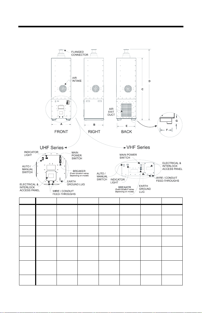
Chapter 1 Introduction
Figure 1 Digital Air Outline Drawing
Series Dim. A Dim. B Dim. C Dim. D Dim. E Dim. F Dim. G
DA10V
DA25V
DA5
DA10
DA15
DA25
DA40
23.5”
(597 mm)
27.0”
(686 mm)
17.0”
(432 mm)
19.5”
(495 mm)
25.0”
(635 mm)
27.0”
(686 mm)
27.5”
(701 mm)
23.5”
(597 mm)
27.0”
(686 mm)
17.0”
(432 mm)
19.5”
(495 mm)
25.0”
(635 mm)
27.0”
(686 mm)
27.5”
(701 mm)
49.5”
(1257 mm)
50.8”
(1289 mm)
55.5”
(1410 mm)
60.0”
(1524 mm)
68.0”
(1727
mm)
68.0”
(1727
mm)
78.8”
(1999 mm)
59”
(1499 mm)
61.0”
(1549 mm)
64.0”
(1626 mm)
68.5”
(1740 mm)
76.5”
(1943
mm)
76.5”
(1943
mm)
84.0”
(2134 mm)
*
N/A
1
N/A
1
N/A
1
N/A
24.5”
(622 mm)
24.5”
(622 mm)
24.5”
(622 mm)
1
N/A
1
N/A
1
N/A
1
N/A
6.0”
(152 mm)
6.0”
(152 mm)
6.0”
(152 mm)
N/A
N/A
N/A
N/A
2.0”
(50.8 mm)
2.0”
(50.8 mm)
2.0”
(50.8 mm)
*. Forklift openings are not provided for these models.
1
1
1
1
1
Page 16

Bird Technologies
Bird Digital Air Load Resistors are air cooled and capable of dissipating RF line power up to 40 kW (depending on the model). Virtually
maintenance free and simple to operate, this unit should provide years
of trouble free operation.
Description
The unit is supported by four bumper feet. The RF input connector is
located on the top of the unit. Fans on all four sides allow for forced air cool
ing of the resistors. The transmitter interlock is located on the front panel.
The model number is printed on a label on the lower left of the unit.
The unit is not intended for exposed outdoor use, or in areas of condensing humidity. Ensure adequate space is available for air circulation.
The Digital Air Load Resistors are offered in a variety of forms differing
in their power ratings, ac input power requirements, frequency ranges,
and connector types (see
Example - A Model DA10F15 is a UHF 10 kW load with a 31/8” flanged connector that requires a 115 V 50/60 Hz power
source.
Figure 2 on page 3 for model numbers).
-
2
Page 17

Figure 2 Digital Air Load Models
Unflanged,
230 Vac
Flanged,
230 Vac
Model Number
Unflanged,
115 VACAC
Introduction
115 VAC
Power Connector Freq. Range Flanged,
5 kW 3-1/8” EIA 470 - 890 MHz DA5F15 DA5U15 DA5F30 DA5U30
10 kW 3-1/8” EIA 470 - 890 MHz DA10F15 DA10U15 DA10F30 DA10U30
15 kW 3-1/8” EIA 470 - 890 MHz DA15F15 DA15U15 DA15F30 DA15U30
25 kW 4-1/16” Myat 470 - 890 MHz DA25F15 DA25U15 DA25F30 DA25U30
25 kW 4-1/2” IEC 470 - 890 MHz DA25-4U15 DA25-4U30
40 kW 4-7/8” IEC 470 - 890 MHz DA40-5U15 DA40-5U30
40 kW 6-1/8” EIA 470 - 890 MHz DA40F15 DA40F30
10 kW 1-5/8” EIA dc - 240 MHz DA10V1F15 DA10V1U15 DA10V1F30 DA10V1U30
10 kW 3-1/8” EIA DC - 240 MHz DA10V3F15 DA10V3U15 DA10V3F30 DA10V3U30
25 kW 3-1/8” EIA dc - 240 MHz DA25V3F15 DA25V3U15 DA25V3F30 DA25V3U30
25 kW 4-1/2” IEC dc - 240 MHz DA25V4U15 DA25V4U30
3
Page 18

Bird Technologies
4
Page 19

Chapter 2 Theory of Operation
The Digital Air Series Loads are high powered, air-cooled, RF loads
used for termination of coaxial transmission lines. The RF energy,
when converted into heat, is transmitted to the surrounding area by a
forced air system.
RF Section Description
The RF section of a Digital Air load is a broadband tuned device composed of tubular ceramic resistors. These are carefully positioned to
produce a very uniform and almost reflectionless line termination over
the stated frequencies of the load resistor.
Heat Removal
When in operation, air is forced into all four sides of the unit and
directed over the RF resistor network. The heat, developed in the resis
tors from dissipation of RF energy, is carried off by the flow of air over
the resistors surface. The hot air is then exhausted through the grille in
the back of the unit.
Fan Activation
The fans on the Digital Air loads are triggered with a pair of normally
open snap disk thermoswitches. The top switch is located in the RF
chamber, while the bottom switch is located in the air exit duct. In
steady state operation, a fan cycle happens as follows:
1. Rising air temperature in the RF chamber closes the top thermoswitch, turning the fans on.
-
2. The hot air is forced into the exit duct by the fans, heating the bottom thermoswitch until it closes.
3. As the cool air is blown into the RF chamber, the top switch
reopens. Since the bottom switch is closed, the fans stay on.
4. When RF power is removed, cool air reaches the exit duct, the bottom
switch opens and the fans turn off.
For power levels substantially below the unit’s power rating, the air in
the exit duct may not heat up sufficiently to close the bottom switch.
As a result, the fans cycle on and off more often. For these power lev
els, it is recommended that the unit be operated in manual mode.
-
5
Page 20

Bird Technologies
Thermal Interlock
All Digital Air loads are supplied with a passive, normally closed, snap
disk overtemperature thermoswitch. Normally closed, the switch opens
above the maximum safe load temperature, turning off the transmitter
power. Because dissipation of the heat generated by the RF power
depends upon forced air cooling, if airflow over the resistor array should
stop or be restricted the temperature in the RF chamber can rise beyond
a safe limit. The heat sensor will sense the change and actuate the
interlock switch to turn off the transmitter. The interlock system will
not permit re-operation of the transmitter until a lower, safe tempera
-
ture in the RF housing is reached.
Line Power Interlock
Digital Air loads are equipped with a line power failure interlock to provide protection against the loss of AC power. The switch is a normally
closed relay. The switch opens if no line power is supplied to the load, the
breaker on the load is tripped, or the power switch on the load has been
turned off. When power is restored, the interlock will reset.
6
Page 21

Chapter 3 Installation
This chapter provides information for on-site requirements, unpacking, inspection, and preparing the Digital Air load for use.
Unpacking and Inspection
1. Carefully inspect the shipping container for signs of damage.
Note: If damage is noticed, do not unpack the unit. Immedi-
ately notify the shipping carrier and Bird Technologies Group.
2. Unpack the unit.
Note: Save the packing materials in case the unit should
need to be shipped again.
3. Inspect all of the components for visible signs of damage.
Note: Immediately notify the shipping carrier and Bird
Technologies Groups.
Unit Placement
Refer to the guidelines in this section when placing the load. Handles
are provided for all models. Forklift openings are provided for larger
models (see
forklift is not recommended.
z Do not use in exposed outdoor locations or in areas of condens-
z Surrounding air must be free of contaminants or particles that
z Digital Air loads have no intermediate dielectric fluid or coolant.
z Digital Air loads are designed to be used upright.
Figure 1). Placement of these models without the use of a
ing humidity.
could be drawn into the air intakes.
No water hookups are required.
Note: Consult the factory for other intended orientations.
Make sure the following open air requirements are met:
7
Page 22

Bird Technologies
CAUTION
Do not block airflow. Air is forced into the housing
via fans on all four sides and exhausts through a
grille on the lower rear of the unit. Blocking air
inputs or exhaust could cause unit failure.
z Do not place the unit in a small room or closet without proper
ventilation.
Note: In restricted areas the heat given off by the unit may
increase the ambient temperature to an unacceptable level.
z Fan intake openings should be at least 4 inches from walls and
obstacles.
Note: Intake air should not exceed maximum ambient
temperatures of 45°C.
z The air exit duct should be at least 24 inches from walls and
obstacles.
z Do not place temperature sensitive equipment near the air
exit, or equipment that will be affected by a rise in ambient air
temperature.
Note: Exit air temperatures can reach in excess of 95°C
depending on environmental conditions.
Ducting Placement
Ducting the unit exhaust is recommended for larger models. Mounting
nuts are provided on the rear of the unit for ducting. Refer to
for the location of the mounting nuts.
Should an external duct be desired, make sure the following requirements are met:
z Maximum 0.2" H2O pressure rise at 45°C ambient.
z All ducts should be at least the area of the air exit duct on the
unit. Refer to Figure 3.
z Ninety degree elbows going up to the ceiling may begin imme-
diately at the load exit. However, they should have a minimum 4 inch radius, >15 inches preferred and should transition
to a larger area.
z Ninety degree elbows into the floor or at right angles to the
floor should start a minimum 5 inches from the load exit and
should have a minimum 4 inch radius, >15 inches preferred
and should transition to a larger area.
8
Figure 3
Page 23

Figure 3 Duct Mounting Location
Access Panel
WARNING
Turn off AC power and RF power before removing or
replacing the access panel; the potential for
electrical shock exists.
Installation
Remove the access panel on the front of the load to connect interlocks,
attach AC power cables, or hard-wire the unit to AC power. For the loca
tion of the access panel see the outline drawing (Figure 1). See Figure 4
for the contents of the power entry box behind the access panel.
Figure 4 Power Entry Box
-
9
Page 24

Bird Technologies
Interlock Connection
CAUTION
Connect interlock before RF operation.
Units are equipped with one of three interlock systems. Refer to the
instructions on the following pages appropriate for individual inter
locks. When connecting terminals to an external interlock, refer to the
transmitter instructions.
Figure 5 Setup for Single External Interlock
-
Five Terminal Interlock with Power Relay
This interlock has five terminals on the load’s interlock connection as
well as an external relay. T-1 and T-2 are the terminals for a thermal
overload switch which trips if the load’s operating temperature is
exceeded. P-1 and P-2 are the terminals for a line power switch which
trips if line power fails. Both switches are normally closed, SPST with
a rating of 10
A @ 120 VAC and 5 A @ 250 VAC.
Note: Line power interlock terminals will not function without
the line power relay installed.
10
Page 25

Installation
To connect both interlocks to a single interlock circuit, wire the
interlock as follows (see
Figure 6 Setup for Separate Thermal and Line Power Interlocks
1. Connect terminals T-2 and P-1.
Figure 6):
Note: T-2 and P-1 are connected when shipped from the
factory.
2. Connect terminal SL to relay pin B. Connect relay pin A to the AC
power NUT terminal.
3. Connect terminal P-1 to relay pin 9. Connect terminal P-2 to relay pin 6.
4. Connect terminals T-1 and P-2 to the transmitter interlock circuit.
For separate thermal and line power interlocks, set the interlock as follows (see Figure 7):
1. Remove the connector between T-2 and P-1.
2. Connect terminals T-1 and T-2 to the thermal overload circuit on
the transmitter.
3. Connect terminal SL to relay pin B. Connect relay pin A to the AC
power NUT terminal.
4. Connect terminal P-1 to relay pin 9. Connect terminal P-2 to relay pin 6.
5. Connect terminals P-1 and P-2 the line power interlock circuit on
the transmitter.
Figure 7 Five Terminal Interlock without Power Relay
11
Page 26

Bird Technologies
Five Terminal Interlock without Power Relay
This interlock has five terminals on the load’s interlock connection,
see
Figure 7. T-1 and T-2 are the terminals for a thermal overload
switch which trips if the load’s operating temperature is exceeded. The
switch is normally closed, SPST with a rating of 10 A @ 120 VAC and 5
A @ 250 VAC. Terminals SL, P-1, and P-2 are not used.
Note: Line power interlock terminals will not function
without the line power relay installed. See "Five Terminal
Interlock with Power Relay" on page 10 for relay instructions.
Two Terminal Interlock
This interlock has two terminals on the load’s interlock connection,
see
Figure . I-1 and I-2 are the terminals for a thermal overload switch
which trips if the load’s operating temperature is exceeded. The switch
is normally closed, SPST with a rating of 10 A @ 120 VAC and 5 A @
250 VAC.
Figure 8 Interlock Two Terminal
AC Power Hookup
CAUTION
Check the local electrical code for proper AC hookup
prior to operation of the unit. Make sure the neutral
or return hookup is only used for that purpose.
The AC power supply required for this unit is 115/230 V @ 50/60 Hz, 1Φ
depending on the model number. See
for current requirements. AC power is supplied through a 3-wire power
cable or by hard wiring the unit with standard 1/2 inch conduit.
AC Power Wire Size Requirements
For DA5 through DA25 and 230 VAC DA40 loads use 18 GA. Copper
stranded insulated wire rated for 1000 VAC and 80°C. For the
115VAC DA40 loads use 14 GA. Copper stranded insulated wire rated
for 1000 VAC and 80°C.
12
"AC Power Required" on page 28
Page 27

Installation
Figure 9 AC Power Connector
AC Power Supply
+
–
External Ground
AC Power Cable
The AC power cable can be threaded through the holes in the access
panel and connected to the terminals. Follow the instructions below to
connect the cable:
WARNING
Ensure the power is turned off when attaching
power cable or wire.
1. Thread the AC power cable through the grommet, lug end first.
2. Thread the AC power cable through the strain relief clamp. Secure
the clamp and cable.
3. Connect the AC power cable to the terminals. See Figure 9.
4. Close and secure the access panel.
Note: The third terminal, labeled “GND”, is the ground. For
proper protection, if a 3-wire type plug and outlet are not used, connect the third terminal to a satisfactory ground at the supply end.
5. Plug the AC power cable into a suitable outlet.
AC Power Cable Strain Relief
When using AC power, use a suitable strain relief compiling with:
z Do not clamp with a screw that bears directly on the cord.
z Do not create knots in the cord.
z Do not push the cord into the equipment to an extent which
could cause a hazardous condition.
z Always use compression bushings designed and approved for
clamping all types and sizes of mains supply cords.
Note: They must at least have a pull strength of 100N, twist
of 0.35 N-m, and either be suitable for connection to the terminals or has been designed to terminate a mains supply cord.
z Ensure that the strain relief does not cause a hazard when the
cord needs to be replaced.
13
Page 28

Bird Technologies
AC Hard Wiring
WARNING
Ensure the power is turned off when attaching
power cable or wire.
1. Remove the grommet from the access panel.
2. Plumb the unit using standard 1/2" conduit.
3. Thread the wires through the conduit.
Note: Make sure the ground line is copper.
4. Connect the AC power wires to the terminals. See Figure 9.
5. Close and secure the access panel.
6. Wire the unit to a suitable AC supply.
7. Provide a means for power disconnection at the AC source.
Earth Grounding Lug
The earth ground is a ¼-20 stud. Use at least a 14 GA, shielded or
unshielded conductor for earth ground termination. Use a suitable
ring lug when securing the earth ground conductor to the unit.
Connecting RF Power
WARNING
Never attempt to connect or disconnect an RF cable
or line while power is on at the RF power source.
Radiated RF energy is a potential health hazard.
After installation of the load, the coaxial RF transmission line may be
attached using standard coaxial transmission line couplers.
Swivel Flanged Coupling
To couple the swivel flange with a flanged RF transmission line, use
an appropriate coupling kit. Refer to
instructions below.
1. Insert the center bullet and push it in until it is fully seated.
2. Connect the coaxial input in a straight line and push carefully on
the center conductor to close.
Figure 10 while following the
Note: The swivel flange on the load makes connection inde-
pendent of the orientation of the fixed flange on the coaxial input
outer conductor.
3. Insert the bolt sets and tighten evenly all around to transmission
line manufacturer’s recommended torque. Use all of the bolts.
14
Page 29

Installation
Figure 10 Swivel Flanged Coupling
Unflanged Coupling
To couple the unflanged connector with an unflanged RF line, use an
appropriate coupling kit. Refer to
Figure 11 while following the
instructions below.
1. Insert the center bullet and bottom it on the midpoint nibs.
2. Position the outer sleeve, with clamping bands, over the input connector.
3. Set the transmission line snugly against the coupling stops.
4. Position the clamping bands evenly about 3/4” from the ends of the
sleeve.
5. Tighten the clamping bands.
Figure 11 Unflanged Coupling
4-1/16” Coupling
The RF connector on Bird 4-1/16 inch loads is built to the Myat Standard. To couple a 4-1/16 inch Myat Standard to a Dielectric Standard
transmission line a special bullet (Myat P/N 401-081) must be used.
The inner conductor interface is not compatible between Myat and
Dielectric. The Myat inner conductor inside diameter is 1.631 inches
and the inner conductor setback from the outer conductor flange face
is 1.375 inches. If help is needed purchasing a Myat bullet, contact
Myat or a Bird service representative.
15
Page 30

Bird Technologies
16
Page 31

Chapter 4 Operating Instructions
The Digital Air Series load has two controls, the ON/OFF switch and
the Manual/Automatic switch. When properly installed, the only
requirements to use the unit as a standby reject load are for the ON/
OFF switch to be in the ON position, and the Manual/Automatic
switch to be in the Automatic position.
Note: AC mains breaker must be set in the ON position.
Before operating the unit, make sure the fans are running or the
“automatic” light is lit. Also, confirm that the inlet air flow is unre
stricted and the exhaust is properly vented. The unit is now ready to
accept RF power. Once the unit has been set up, there is no need for
the presence of an operator.
WARNING
Exhausted air may exceed 95°C (203°F).
Automatic Mode
When the load is in automatic mode, the fans will turn on only when
the load requires forced air to keep the temperature in the RF cham
ber below a safe limit. The fans may cycle on and off during warm-up.
This cycling is normal and is dependent upon the applied input power.
-
-
Manual Mode
When the load is in manual mode, the fans run continuously. This
mode is recommended for power levels substantially below the unit’s
power rating to prevent excessive fan cycling.
Load Operation
1. Turn on the AC power.
CAUTION
Do not operate without AC power to the load.
2. Verify all four fans are operating.
3. Select Automatic or Manual fan control.
17
Page 32

Bird Technologies
4. Turn the interlock supply on at the transmitter.
CAUTION
Applying more than the rated average RF power to
the load may damage the load resistors.
5. Apply RF power to the load.
WARNING
Do not operate above the rated capacity. See
“Specifications” on page 27 if unsure of the rating
the model load. The unit will handle a small
percentage of overload for brief periods of time
during transmitter tuning or adjustment. However,
long periods of overload (> 10% of rated power for >
30 min.) may damage the unit or cause the
temperature interlock to open.
Interlock Operation
The overtemperature interlock is set for proper operation at the maximum rated ambient temperature of 45°C (113°F). The normally closed
switch opens at 86°C ± 5°C (186.8°F ± 9°F) and closes at 65°C ± 3°C
(149°F ± 5.4°F). This interlock is not dependent on AC line power.
Note: The power interlock is set for proper operation when
the load is connected to AC power, the power switch is on, and
the circuit breakers are not tripped.
Manual Shut Down
When operation of the load has been completed, follow these steps for
shut down.
CAUTION
Do not disconnect AC line power before turning off
RF power to the load. Application of full RF power to
the load while the fans are unpowered will cause the
load to overheat and destroy the resistor elements.
1. Turn the RF power to the load off.
2. Wait about 10 minutes to allow the air circulation to cool the resistive elements inside the load to ambient temperature.
Note: This cooling period will prevent unnecessary heat
stress on the resistors.
3. Turn off the AC power.
4. Disconnect the RF line.
18
Page 33

Operating Instructions
Automatic Shut Down
When operations are completed, turn the RF power to the load off. The
load fans will stay on until the load is cool, then they will shut off.
Measurement and Monitoring of RF Power
The Digital Air Series load may be used in conjunction with any of the
Bird rigid coaxial line power meters. When fitted with the appropriate line
section and wattmeter, the combination is a useful tool for tuning and
adjusting a transmitter as well as monitoring RF power directly in watts.
Broadcasters involved in the transmission of high definition television, digital audio broadcast, or other signals with complex modulation should use Bird Broadcast Power Monitors (BPM) for the
measurement of true average power in these systems. BPMs are also
required in applications where multiple carriers are present in the
transmission system simultaneously, as in the case of post combiner
power measurements. Conventional broadcast power meters will pro
duce erroneous readings in the presence of complex modulation due to
the high peak to average power ratio of these signals. Contact a Bird
sales representative for more information.
-
19
Page 34

Bird Technologies
20
Page 35

Chapter 5 Maintenance
Troubleshooting
WARNING
Disconnect this unit from the RF power sources and
the AC line before any disassembly. The potential
for electrical shock exists.
For corrections requiring repair or replacement of components see the
appropriate section. Only those functions within the scope of normal
maintenance are listed. This manual cannot list all malfunctions that
may occur, or corrective actions. If a malfunction is not listed or is not
corrected by listed corrective actions, notify a qualified service center.
.
Problem Possible Cause Possible Correction
Overtemperature
interlock is active.
AC power interlock
is active, or no “ON”
indicator lit (neither
automatic nor
manual light).
High VSWR Poor flange
Overheating Make sure air input and output
openings are not restricted. See
“Unit Placement” on page 7.
Reduce RF power.
One or more fans
failing.
No AC power Make sure AC power is properly
ON/OFF switch is off. Turn the switch on.
Open circuit breaker. Reset the circuit breaker.
connection.
One or more resistors
failing.
Make sure AC power is properly
connected and turned on. See
“AC Power Hookup” on page 12.
Contact the Bird Service Group for
replacement. See “Customer
Service” on page 23.
connected and turned on. See
“AC Power Hookup” on page 12.
Make sure the flange connection
is hooked up properly. See
“Interlock Connection” on
page 10.
Contact the Bird Service Group for
replacement. See “Customer
Service” on page 23.
21
Page 36

Bird Technologies
Cleaning and Inspection
A main factor in effective preventive maintenance is cleanliness. For
optimum performance and service life, the load must be kept in a
clean, dust-free condition.
The following steps can be used to maintain cleanliness of the unit.
z The outside surface of the load should be wiped free of dust
and dirt when necessary.
z Check the condition of the RF coaxial connection occasionally.
z If required, disconnect the unit from the transmission line and
clean the RF connector parts, both metallic and insulator surfaces.
Note: When cleaning these parts and all other electrical
parts, use a dry cleaning solvent that leaves no residue.
Preparation for Storage or Shipment
Storage
Note: There is no special preparation for the unit.
1. Cover the equipment to keep out dust and dirt.
2. Store the unit in a dust-free, dry environment with an ambient temperature range of -40°C to 45°C (-40°F to +113°F) and the relative
humidity should remain low.
Shipment
1. Secure all loose parts such as the swivel flange.
2. Pack the unit securely in a sturdy wooden box or equivalent.
Note: If possible, keep the original shipping carton for
reshipment.
3. Pad the container with sufficient padding to avoid shock damage.
4. Seal the container securely.
22
Page 37

Maintenance
Customer Service
Any maintenance or service procedure beyond the scope of those in
this chapter should be referred to a qualified service center.
If you need to return the unit for any reason, request an RMA through
the Bird Technologies website (link shown below). All instruments
returned must be shipped prepaid and to the attention of the RMA
number.
Bird Service Center
30303 Aurora Road
Cleveland (Solon), Ohio 44139-2794
Fax: (440) 248-5426
E-mail: bsc@bird-technologies.com
For the location of the Sales Office nearest you, visit our website at:
http://www.bird-technologies.com
23
Page 38

Bird Technologies
Circuit Diagram
The following circuit diagram identifies the function of the internal
wiring of the load. This information is for use by trained service per
sonnel only.
WARNING
Improper wiring could result in electric shock and
death.
WARNING
Turn off AC power and RF power before removing or
replacing the access panel, the potential for electrical
shock exists.
WARNING
High heat present inside unit! Let cool for at least 10
minutes before servicing or severe burns could result.
WARNING
Maintenance by other than trained service personnel
could result in electric shock.
-
24
CAUTION
Improper wiring could disable load.
CAUTION
Do not disable fans. Application of full RF power to
the load while the air circulation is off will cause the
load to overheat and destroy the resistor elements.
CAUTION
All replacement wiring must be 18 AWG, with
insulation rated to 400º F (205º C). Use of other
wiring could result in unit damage.
CAUTION
This circuit diagram for use by trained service
personnel only. Improper use could disable load.
Page 39

Figure 12 Digital Air Load Circuit Diagram 1
Maintenance
25
Page 40

Bird Technologies
Figure 13 Digital Air Load Circuit Diagram 2
26
Page 41

Specifications
Impedance 50 ohm nominal
VSWR 1.10:1 maximum, 1.05:1 typical
Connectors (Model Dependent)
1-5/8” EIA Flanged 1-5/8” Unflanged
3-1/8” EIA Flanged 3-1/8” Unflanged
4-1/16” Myat Flanged 4-1/16” Myat Unflanged
4-1/2” IEC Unflanged 4-7/8” IEC Unflanged
6-1/8” EIA Flanged
Power Rating
DA5 Series
DA10 & DA10V Series
DA15 Series
DA25 & DA25V Series
DA40 Series
Peak to Average Power Ratio
Model DA40 series only
All other models
Frequency Range
DA10V & DA25V Series
DA5, DA10, DA15, DA25, &
DA40 Series
Dimensions
DA10V Series
DA25V Series
DA5 Series
DA10 Series
DA15 Series
DA25 Series
DA40 Series
Ambient Temperature -40°C to +45°C (-40°F to +113°F)
Storage Temperature -40°C to +70°C (-40°F to +158° F)
Humidity 30% to 95% (non-condensing)
Altitude See Figure 14 and Figure 15
Interlock contact rating 10 Amp @ 120 VAC
5 kW continuous duty
10 kW continuous duty
15 kW continuous duty
25 kW continuous duty
40 kW continuous duty
†
>14dB
>10dB
DC-240 MHz
470-890 MHz
23.5"L x 23.5"W x 59"H (597 x 597 x 1499 mm)
27"L x 27"W x 61.0"H (686 x 686 x 1549 mm)
17"L x 17"W x 64.0"H (432 x 432 x 1626 mm)
19.5"L x19.5"W x 68.5"H (495x495x1740mm)
25"L x 25"W x 76.5"H (635 x 635 x 1943 mm)
27"L x 27"W x 76.5"H (686 x 686 x 1943 mm)
27.5"L x 27.5"W x 84.0"H (701x701x2134 mm)
5 Amp @ 250 VAC
Maintenance
*
27
Page 42

Bird Technologies
AC Power Required
DA10V Series
DA25V Series
DA5 Series
DA10 Series
DA15 Series
DA25 Series
DA40 Series
‡
115V 230V @ 50/60 Hz, 1 φ
3.2A 2.0A
9.0A 5.0A
3.2A 2.0A
3.2A 2.0A
9.0A 5.0A
10.0A 5.0A
20.0A 10.0A
Breaker Rating Refer to the breaker rating label on the unit.
Safety EN 61010-1:2001
EMC Emissions, EN 50081-1:1992
Emissions, EN 50081-1:1992
Harmonics, EN 61000-3-2:1995
Flicker, EN 61000-3-3:1995
ESD, EN 61000-4-2:1995
Radiated Immunity,
EN 61000-4-3:1995
Electrical Fast Transient/Burst,
EN 61000-4-4:1995
Surge, EN 61000-4-5:1995
Conducted, EN 61000-4-6:1995
Voltage Dips and Interrupts,
EN 61000-4-11:1995
Cooling Method Forced air cooled
Weight, Nominal
DA5 Series
DA10, DA10V Series
DA15 Series
DA25 Series
DA25V Series
DA40 Series
100 lbs. (45.5 kg)
130 lbs. (59.0 kg)
192 lbs. (87.1 kg)
245 lbs. (111.1 kg)
150 lbs. (68.0 kg)
310 lbs. (140.6 kg)
Finish Blue Powder Coat
*. Typical value of the VSWR over the frequency range of the unit is 1.05:1.
This is representative of the average VSWR for the unit in question.
†. The Duty Factor should be such that the Average Power Rating of the load
is never exceeded.
‡. AC voltage must be within +10%, –6% of listed value.
28
Page 43

Figure 14 UHF Loads Derating
Altitude De-rating
Digital Air UHF Series:
DA5, DA10, DA15, DA25, DA40
Maintenance
40
35
DA40
30
25
20
DA25
15
DA15
Maximum Allowable Average Power (kW)
10
DA10
5
DA5
0
0 2500 5000 7500 10000 12500 15000
Altitude Above Sea Level (ft)
60HZ, 25C
50Hz, 25C
60Hz, 45C
50Hz, 45C
60Hz, 25C
50Hz, 25C
60Hz, 45C
50Hz, 45C
60Hz, 25C
50Hz, 25C
60Hz, 45C
50Hz, 45C
60Hz, 25C
50Hz, 25C
60Hz, 45C
50Hz, 45C
60Hz, 25C
50Hz, 25C
60Hz, 45C
50Hz, 45C
29
Page 44

Bird Technologies
Figure 15 VHF Loads Derating
Altitude De-rating
Digital Air VHF Series:
DA10V, DA25V
25
DA25V
20
15
60Hz, 25C
50Hz, 25C
60Hz, 45C
50Hz, 45C
60Hz, 25C
50Hz, 25C
60Hz, 45C
50Hz, 45C
10
DA10V
Maximum Allowable Average Power (kW)
5
0
0 2500 5000 7500 10000 12500 15000
Altitude Above Sea Level (ft)
30
60Hz, 25C
50Hz, 25C
60Hz, 45C
50Hz, 45C
Page 45

Appendix 1 Difference Data Sheet
Specifications for 12.5 kW Digital Air Load
All specifications are the same as the DA10F15, see “Specifications” on
page 27, with following exceptions:
Power Rating 12.5 kW continuous duty
Ambient Temperature -40°C to +30°C (-40°F to +86°F)
Altitude 2500 ft. max.
AC Power Required 115Vac, 3.0A, 60 Hz, 1Φ
31
Page 46

Bird Technologies
Limited Warranty
All products manufactured by Seller are warranted to be free from
defects in material and workmanship for a period of one year, unless
otherwise specified, from date of shipment and to conform to applica
ble specifications, drawings, blueprints and/or samples. Seller’s sole
obligation under these warranties shall be to issue credit, repair or
replace any item or part thereof which is proved to be other than as
warranted; no allowance shall be made for any labor charges of Buyer
for replacement of parts, adjustment or repairs, or any other work,
unless such charges are authorized in advance by Seller.
If Seller’s products are claimed to be defective in material or workmanship or not to conform to specifications, drawings, blueprints and/
or samples, Seller shall, upon prompt notice thereof, either examine
the products where they are located or issue shipping instructions for
return to Seller (transportation-charges prepaid by Buyer). In the
event any of our products are proved to be other than as warranted,
transportation costs (cheapest way) to and from Seller’s plant, will be
borne by Seller and reimbursement or credit will be made for amounts
so expended by Buyer. Every such claim for breach of these warranties
shall be deemed to be waived by Buyer unless made in writing within
ten days from the date of discovery of the defect.
The above warranties shall not extend to any products or parts thereof
which have been subjected to any misuse or neglect, damaged by acci
dent, rendered defective by reason of improper installation or by the
performance of repairs or alterations outside of our plant, and shall
not apply to any goods or parts thereof furnished by Buyer or acquired
from others at Buyer’s request and/or to Buyer’s specifications. In
addition, Seller’s warranties do not extend to the failure of tubes, tran
sistors, fuses and batteries, or to other equipment and parts manufactured by others except to the extent of the original manufacturer’s
warranty to Seller.
The obligations under the foregoing warranties are limited to the precise terms thereof. These warranties provide exclusive remedies,
expressly in lieu of all other remedies including claims for special or
consequential damages. SELLER NEITHER MAKES NOR
ASSUMES ANY OTHER WARRANTY WHATSOEVER, WHETHER
EXPRESS, STATUTORY, OR IMPLIED, INCLUDING WARRAN
TIES OF MERCHANTABILITY AND FITNESS, AND NO PERSON
IS AUTHORIZED TO ASSUME FOR SELLER ANY OBLIGATION
OR LIABILITY NOT STRICTLY IN ACCORDANCE WITH THE
FOREGOING.
-
-
-
-
32
Page 47

33
 Loading...