

Page 1
Broadcast Power Monitor
BPME Series
This innovative product offers users more options in how they measure, monitor and protect their
RF Broadcast transmission systems while providing dependable performance and accuracy.
While the BPME provides the usual power and VSWR monitoring, it is much more than just a ‘comfort’ meter. One of the chief factors that
sets BPME apart is the depth of its functionality. From remote monitoring via a user-friendly web interface to data logging
capabilities, the BPME gives users a range of functions designed to make their jobs easier, while protecting the health of their investment.
In addition, the RF test port enables users to verify spectral compliance for applications such as IBOC or HDTV at the point in the
transmission line where it matters most! The enhanced functionality of BPME puts complete analog and digital broadcast monitoring at the user's fingertips through user-friendly, around-the-clock, remote access from any web-enabled device. This 24/7 access
ensures that problems are detected and dealt with easily and promptly-before they escalate into more costly situations.
Features/Benefits
Integral Power Monitor System
}
Integration of forward and reflected elements into
the RF Detection/Control Circuit yields added stability
and greater dynamic range.
Frequency/Channel Field Congurable
} Provides channel flexibility when needed in the field.
Ethernet & RS-232 Enabled
} Future-ready remote monitoring, control & instant
alarm alert.
Integral RF Test Port
} Enables mask compliance testing, as well as monitoring
of spectrum, modulation, frequency & RF envelope
performance.
Data Logging Capabilities
} System trends and anomalies can be detected before
failures.
Product Highlights
Re-engineered to integrate the forward & reected
elements into the RF Detection/Control circuit to
yield added stability and greater dynamic range.
DB-15 connector for
power input to BPME.
Additionally, this provides
analog alarm and relay
data output to the 3129
Display Panel or any PC
equipped with PC Tool
Software.
DB-9 connector, RS-232 output to 3129
Display Panel or any PC equipped with
PC Tool Software. Alarm upon zero
pow er, l ow power, high power or
VSWR anomalies as per customer set
threshold.
RJ-45 connector, Ethernet enabled.
Remote interface to the BPME via
any PC via the web.
Silver plated, copper line
sections available in standard
EIA line sizes. Consult factory
for specific configurations to
meet your requirement.
High quality, low loss, handformable
microwave cable ensures measurement
accuracy.
Integrated RF Test Port for use with optional
Sampling Elements. This is critical for
applications where spectral compliance
must be veried. Additionally, this port can
be used to monitor spectrum, modulation,
frequency and RF envelope performance.
Page 2
Broadcast Power Monitors
BPME Series
APPLICATIONS
TYPICAL INSTALLATION DIAGRAM
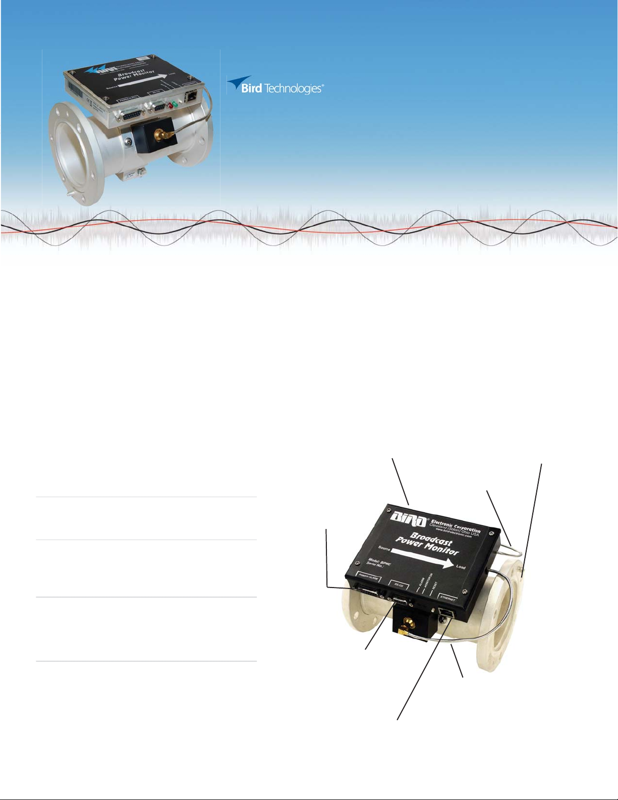
1. 3129 DIGITAL DISPLAY
2. RS-232 COMMUNICATION PORT, DB-9
3. POWER/ALARM CONNECTOR, DB15
4. ETHERNET CONNECTOR
5. COMPUTER (NOT ON A NETWORK)
6. MONITOR PORT
7. MONITOR DEVICE
OSCILLOSCOPE)
8. DETECTION/CONTROL MODULE
9. CELL PHONE OR PDA-INSTANT MESSAGE
NOTIFICATION OF ALARM
(FOR NETWORK OR LOCAL PC)
(SPECTRUM ANALYZER, MODULATION MONITOR,
Measuring RF power and system match characteristics can be made with the
BPME in any installation, regardless of the signal waveform. Complex waveforms
such as 8-VSB and COFDM, used in IBOC, DAB and HDTV systems, as well as FM,
AM and CW signals are accurately measured to ensure total power output
requirements.
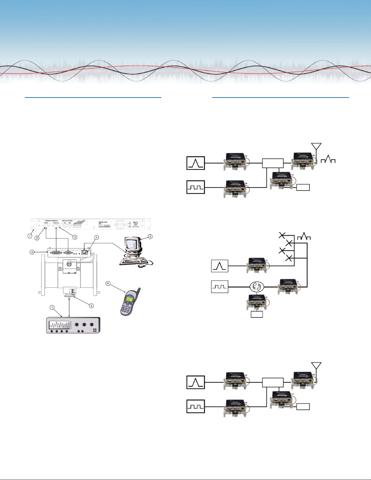
HIGH-LEVEL COMBINED
Combiner/Coupler
Transmitter
Transmitter
HD Radio is combined with the analog signal at the input to the antenna. Analog
powercoupled to the digital transmitter must be considered when specifying
the BPME. The 20 dB dynamic range of the BPME will allow for easy high-level
combined installations.
INTERLEAVED ANTENNA
Transmitter
Load
Transmitter
Load
HD Radio and an analog signal can use interleaved antennas for separate but
simultaneous transmission. High isolation reduces the mutual coupling however,
analog power coupled to the digital transmitter must be considered when
specifying the BPME. With 20 dB of dynamic range, the BPME is ready to handle
this type of installation.
MULTI-STATIONS
Combiner/Coupler
Transmitter
Transmitter
Multi-station operation will have a high peak-to-average power ratio, depending
on the number of stations combined. Power meters not equipped to handle this
high ratio will display accuracy errors up to 20%. With the ability to accurately
read greater than 10 dB peak-to-average power, the BPME is your choice for
multi-station applications.
Load
Page 3

Broadcast Power Monitors
BPME Series
SPECIFICATIONS
BPME OPERATING CHARACTERISTICS
Frequency Range See chart
Forward Power
Measurement Type In-line, True Average Power
Peak/Average Ratio 10 dB
Coupler Directivity 26 dB min., 30dB Typical
Accuracy ±5% of reading
Alarms VSWR, No/Low Forward Power, High Forward Power
Outputs SPDT relay contact
Display Options BPME PC Software, 3129
Remote Interface Ethernet 10BASE-T or
See chart
Range
100BASE-TX (auto-sensing)
Ethernet Version 2.0/IEEE 802.3
Protocols: ARP, UDP/IP, TCP/IP, Telnet,
ICMP, SNMP, DHCP, BOOTP, TFTP, Auto IP, and HTTP
Security: 256-bit encryption
Serial RS-232, 9600 baud, no parity,
8 data bits, 1 stop bit, no handshake
FORWARD POWER RANGE
Line Size Power Designator VHF (45-230 MHz) UHF (470-890 MHz)
7/8” Low
1 5/8” Low
3 1/8” Low
4 1/16”
&
4 1/2”
6 1/8” Low
Medium
High
Medium
High
Medium
High
Low
Medium
High
Medium
High
5W – 500 W
20 W – 2000 W
50 W – 5000 W
20 W – 2000 W
80 W – 8 kW
200W – 20 kW
50 W – 5000 W
200 W – 20 kW
500 W – 50 kW
100 W – 10 kW
400 W – 40 kW
1000 W – 100 kW
200 W – 20 kW
800 W – 80 kW
2000 W – 200 kW
2.5 W – 250 W
10 W – 1000 W
25 W – 2500 W
5 W – 500 W
20 W – 2000 W
50 W – 5000 W
25 W – 2500 W
100 W– 10 kW
250 W – 25 kW
40 W – 4 kW
150 W – 15 kW
400 W – 40 kW
80 W – 8 kW
300 W – 30 kW
750 W – 75 kW
MODEL 3129 BROADCAST POWER METER
Operating Voltage 115/230 VAC @ 50/60 Hz
Operating Power Less than 10 watts
Dimensions 5.25" X 19" X 1.75"
(133.35 mm X 483 mm X 44.5 mm)
Weight Approximately 2 lbs. (0.85 kg)
Supplied with 50 feet of cable to connect RS-232 and serial
ports between 3129 and line section, and
serial interface cable
LINE SECTION
Operating Temp. 0°C to +50°C (32°F to 122°F)
Storage Temp. -20°C to + 80°C (-4°F to 176°F)
Humidity 95% ±5% max. (noncondensing)
Altitude up to 10,000 feet (3,048 m)
Calibration cycle Annual
Consult our Applications Engineers at Bird Technologies Group today for assistance in
choosing the BPME best suited for your installation.
Page 4

Broadcast Power Monitors
BPME Series
MODEL NOMENCLATURE (7/8” LINE SECTIONS)
BPME
Line Section
7 = 7/8”
7
Input Connector
A = N (F)
B = N (M)
C = LC (F)
D = 7/8” EIA
H = DIN (F)
J = DIN (M)
K = UHF (F)
L = UHF (M)
Output Connector
A = N (F)
B = N (M)
C = LC (F)
D = 7/8” EIA
H = DIN (F)
J = DIN (M)
K = UHF (F)
L = UHF (M)
Frequency Band
VL = 45-88 MHz
V = 88-230 MHz
U = 470-890 MHz
Power*
L = Low
M = Medium
H = High
*see chart for
power ranges
MODEL NOMENCLATURE (1 5/8”, 3 1/8”, 4 1/16”, 4 1/2 AND 6 1/8” LINE SECTIONS)
BPME
Line Section
1 = 1 5/8”
3 = 3 1/8”
4 = 4 1/16”
4A = 4 1/2
6 = 6 1/8”
Line Interface*
U = Unanged, Recessed
Center Conductor
UF = Unanged, Flush
Center Conductor
D = Dielectric Flanged
M = Myat Flanged
*For Flanged, leave blank
Frequency Band
VL = 45-88 MHz
V = 88-230 MHz
U = 470-890 MHz
Power*
L = Low
M = Medium
H = High
*see chart for power ranges
P = Panel Mount
*leave blank for no
panel
30303 Aurora Rd. Solon, OH 44139 866.695.4569 www.bird-technologies.com
 Loading...