

Page 1

INSTRUCTION BOOK
BLOWER ASSEMBLY
MODELS BA-300 & BA-310
©Copyright 1997, 2002, 2008 by Bird Electronic Corporation
Instruction Book Part Number 920-BA-300/310 Rev. G
Termaline
®
and Tenuline® are Registered Trademarks
of Bird Electronic Corporation
Page 2

This page intentionally left blank
Page 3

Safety Precautions
The following are general safety precautions that are not necessarily
related to any specific part or procedure and do not necessarily appear
elsewhere in this publication. These precautions must be thoroughly
understood and apply to all phases of operation and maintenance.
Keep Away From Live Circuits
Operating personnel must at all times observe normal safety regulations.
Do not replace components or make adjustments inside the equipment
with high voltage turned on. To avoid casualties, always remove power.
Shock Hazard
Do not attempt to remove the RF transmission line while RF power is
present.
Do Not Service or Adjust Alone
Under no circumstances should any person reach into an enclosure for the
purpose of service or adjustment of equipment except in the presence of
someone who is capable of rendering aid.
Safety Earth Ground
An uninterruptible earth safety ground must be supplied from the main
power source to test instruments. Grounding one conductor of a two
conductor power cable is not sufficient protection. Serious injury or death
can occur if this grounding is not properly supplied.
Chemical Hazard
Dry cleaning solvents used to clean parts may be potentially dangerous.
Avoid inhalation of fumes and also prolonged contact with skin.
Resuscitation
Personnel working with or near high voltages should be familiar with
modern methods of resuscitation.
i
Page 4
Bird BA–300/310 Blower Assembly
Safety Symbols
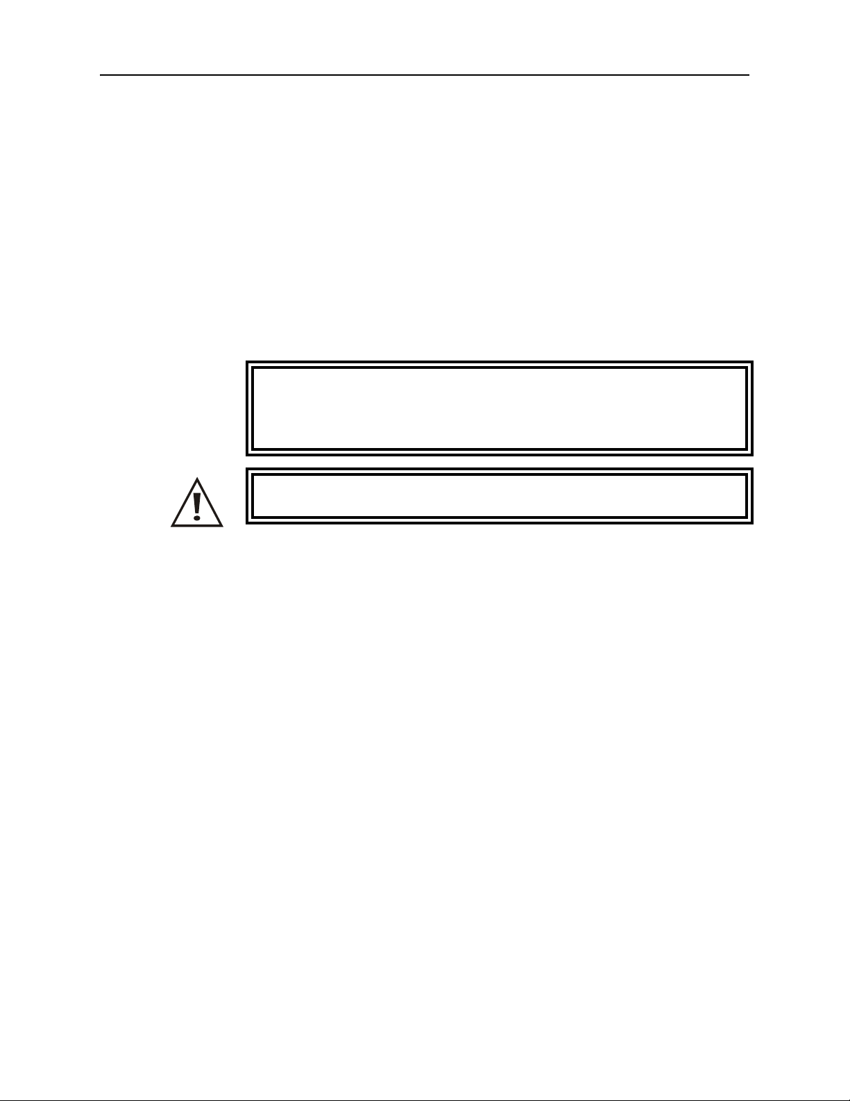
Warning notes call attention to a procedure which, if not correctly
performed, could result in personal injury.
Caution notes call attention to a procedure which, if not correctly
performed, could result in damage to the instrument.
The caution symbol appears on the equipment indicating
there is important information in the instruction manual
regarding that particular area. See page 8 for specific
cautions.
This symbol indicates that a shock hazard exists if the
precautions in the instruction manual are not follwed.
WARNING
CAUTION
+ NOTE: Calls attention to supplemental information.
Warning Statements
The following safety warnings appear in the text where there is danger to
operating and maintenance personnel and are repeated here for emphasis.
WARNING
The vent plug must be used at all times when the load is
operating or cooling. Failure to do so could result in an
explosion or severe burns.
WARNING
Disconnect the unit from all power sources before servicing.
The unit may be energized from multiple sources.
The potential for electric shock exists.
WARNING
Never attempt to connect or disconnect RF equipment from the
transmission line while RF power is being applied.
Leaking RF energy is a potential health hazard.
WARNING
Do not operate with side panel removed.
ii
Page 5
WARNING
Turn off ac power and RF power when attaching the power cable.
Caution Statements
The following equipment cautions appear in the text whenever the
equipment is in danger of damage and are repeated here for emphasis.
CAUTION
The BA system is designed for operation in a horizontal position only,
with the load’s vent plug up. Do not use in any other manner.
CAUTION
If installed, connect optional interlock before applying RF power.
CAUTION
Check the local electrical code for proper ac hookup prior to
operation of the unit. Make sure the neutral or return hookup
is only used for that purpose.
CAUTION
The Bird BA–300/310 Blower Assembly will derate a load’s specified
power by 50% when installed and not running. If the indicator light
should turn off, immediately reduce RF power by at least 75%.
Safety Statements
USAGE
ANY USE OF THIS INSTRUMENT IN A MANNER NOT
SPECIFIED BY THE MANUFACTURER MAY IMPAIR THE
INSTRUMENT’S SAFETY PROTECTION.
USO
EL USO DE ESTE INSTRUMENTO DE MANERA NO ESPECIFICADA
POR EL FABRICANTE, PUEDE ANULAR LA PROTECCIÓN DE
SEGURIDAD DEL INSTRUMENTO.
BENUTZUNG
WIRD DAS GERÄT AUF ANDERE WEISE VERWENDET ALS VOM
HERSTELLER BESCHRIEBEN, KANN DIE GERÄTESICHERHEIT
BEEINTRÄCHTIGT WERDEN.
UTILISATION
iii
Page 6

Bird BA–300/310 Blower Assembly
TOUTE UTILISATION DE CET INSTRUMENT QUI N’EST PAS
EXPLICITEMENT PRÉVUE PAR LE FABRICANT PEUT
ENDOMMAGER LE DISPOSITIF DE PROTECTION DE
L’INSTRUMENT.
IMPIEGO
QUALORA QUESTO STRUMENTO VENISSE UTILIZZATO IN MODO
DIVERSO DA COME SPECIFICATO DAL PRODUTTORE LA
PROZIONE DI SICUREZZA POTREBBE VENIRNE COMPROMESSA.
SERVICE
SERVICING INSTRUCTIONS ARE FOR USE BY SERVICE TRAINED PERSONNEL ONLY. TO AVOID DANGEROUS
ELECTRIC SHOCK, DO NOT PERFORM ANY SERVICING
UNLESS QUALIFIED TO DO SO.
SERVICIO
LAS INSTRUCCIONES DE SERVICIO SON PARA USO EXCLUSIVO
DEL PERSONAL DE SERVICIO CAPACITADO. PARA EVITAR EL
PELIGRO DE DESCARGÉAS ELCTRICAS, NO REALICE NINGÚN
SERVICIO A MENOS QUE ESTÉ CAPACITADO PARA HACERIO.
WARTUNG
ANWEISUNGEN FÜR DIE WARTUNG DES GERÄTES GELTEN NUR
FÜR GESCHULTES FACHPERSONAL.
ZUR VERMEIDUNG GEFÄHRLICHE, ELEKTRISCHE SCHOCKS,
SIND WARTUNGSARBEITEN AUSSCHLIEßLICH VON
QUALIFIZIERTEM SERVICEPERSONAL DURCHZUFÜHREN.
ENTRENTIEN
L’EMPLOI DES INSTRUCTIONS D’ENTRETIEN DOIT ÊTRE
RÉSERVÉ AU PERSONNEL FORMÉ AUX OPÉRATIONS
D’ENTRETIEN. POUR PRÉVENIR UN CHOC ÉLECTRIQUE
DANGEREUX, NE PAS EFFECTUER D’ENTRETIEN SI L’ON N’A PAS
ÉTÉ QUALIFIÉ POUR CE FAIRE.
ASSISTENZA TECNICA
LE ISTRUZIONI RELATIVE ALL’ASSISTENZA SONO PREVISTE
ESCLUSIVAMENTE PER IL PERSONALE OPPORTUNAMENTE
ADDESTRATO. PER EVITARE PERICOLOSE SCOSSE ELETTRICHE
NON EFFETTUARRE ALCUNA RIPARAZIONE A MENO CHE
QUALIFICATI A FARLA.
iv
Page 7

About This Manual
This instruction book covers the following models:
BA–300–115 BA–310–115
BA–300–230 BA–310–230
This instruction book is arranged so that essential information on safety
is contained in the front of the book. Reading the Safety Precautions
Section before operating the equipment is strongly advised.
The remainder of this Instruction Book is divided into Chapters and
Sections. At the beginning of each chapter a general overview will be
given, describing the contents of that chapter.
Operation
First time operators should read Chapter 1 – Introduction, and Chapter 3
– Installation, to get an overview of equipment capabilities and how to
install it. An experienced operator can refer to Chapter 4 – Operating
Instructions. All instructions necessary to operate the equipment, are
contained in this section.
Maintenance
All personnel should be familiar with preventative maintenance found in
Chapter 5 – Maintenance. If a failure should occur, the troubleshooting
section will aid in isolating and repairing the failure. Parts lists and
repair instructions are also in this chapter.
Changes
We have made every effort to ensure this manual is accurate at the time
of publication. If you should discover any errors or if you have suggestions
for improving this manual, please send your comment to our factory. This
manual may be periodically updated, when inquiring about updates to
this manual refer to the part number and revision level on the title page.
v
Page 8

Table of Contents
Safety Precautions . . . . . . . . . . . . . . . . . . . . . . . . . . . . i
About This Manual . . . . . . . . . . . . . . . . . . . . . . . . . . . . v
Introduction . . . . . . . . . . . . . . . . . . . . . . . . . . . . . . . . 1
Items Furnished . . . . . . . . . . . . . . . . . . . . . . . . . . . . . . . . . . . . . . . . . . . . . . 1
Items Required but Not Supplied . . . . . . . . . . . . . . . . . . . . . . . . . . . . . . . . . 1
Optional Accessories . . . . . . . . . . . . . . . . . . . . . . . . . . . . . . . . . . . . . . . . . . 1
Theory of Operation. . . . . . . . . . . . . . . . . . . . . . . . . . . . 3
Power Rating Reduction . . . . . . . . . . . . . . . . . . . . . . . . . . . . . . . . . . . . . . . . 3
Installation. . . . . . . . . . . . . . . . . . . . . . . . . . . . . . . . . 5
Unpacking and Inspection. . . . . . . . . . . . . . . . . . . . . . . . . . . . . . . . . . . . . . . 5
Mounting . . . . . . . . . . . . . . . . . . . . . . . . . . . . . . . . . . . . . . . . . . . . . . . . . . . . 5
Installing Thermoswitch (BA–310 Only) . . . . . . . . . . . . . . . . . . . . . . . . . . . . 6
Thermoswitch Connection (BA–310 Only) . . . . . . . . . . . . . . . . . . . . . . . . . . 7
Load Resistor . . . . . . . . . . . . . . . . . . . . . . . . . . . . . . . . . . . . . . . . . . . . . . . . 8
AC Power Hookup . . . . . . . . . . . . . . . . . . . . . . . . . . . . . . . . . . . . . . . . . . . . 8
Operating Instructions . . . . . . . . . . . . . . . . . . . . . . . . . . 9
BA–300 Controls . . . . . . . . . . . . . . . . . . . . . . . . . . . . . . . . . . . . . . . . . . . . . 9
BA–310 Controls . . . . . . . . . . . . . . . . . . . . . . . . . . . . . . . . . . . . . . . . . . . . . 9
Normal Operation . . . . . . . . . . . . . . . . . . . . . . . . . . . . . . . . . . . . . . . . . . . . . 9
Operation Under Abnormal Conditions . . . . . . . . . . . . . . . . . . . . . . . . . . . . . 9
Shutdown . . . . . . . . . . . . . . . . . . . . . . . . . . . . . . . . . . . . . . . . . . . . . . . . . . 10
Emergency Shutdown. . . . . . . . . . . . . . . . . . . . . . . . . . . . . . . . . . . . . . . . . 10
Maintenance. . . . . . . . . . . . . . . . . . . . . . . . . . . . . . . 11
Troubleshooting . . . . . . . . . . . . . . . . . . . . . . . . . . . . . . . . . . . . . . . . . . . . . . . . 11
Maintenance . . . . . . . . . . . . . . . . . . . . . . . . . . . . . . . . . . . . . . . . . . . . . . . . . . . 12
Cleaning . . . . . . . . . . . . . . . . . . . . . . . . . . . . . . . . . . . . . . . . . . . . . . . . . . . 12
Inspection . . . . . . . . . . . . . . . . . . . . . . . . . . . . . . . . . . . . . . . . . . . . . . . . . . 12
Repair. . . . . . . . . . . . . . . . . . . . . . . . . . . . . . . . . . . . . . . . . . . . . . . . . . . . . . . . 13
Fuse . . . . . . . . . . . . . . . . . . . . . . . . . . . . . . . . . . . . . . . . . . . . . . . . . . . . . . 13
vi
Page 9

Indicator Light . . . . . . . . . . . . . . . . . . . . . . . . . . . . . . . . . . . . . . . . . . . . . . 13
Fan . . . . . . . . . . . . . . . . . . . . . . . . . . . . . . . . . . . . . . . . . . . . . . . . . . . . . . 14
Storage and Shipment . . . . . . . . . . . . . . . . . . . . . . . . . . . . . . . . . . . . . . . . . . 16
Customer Service . . . . . . . . . . . . . . . . . . . . . . . . . . . . . . . . . . . . . . . . . . . . . . 16
Specifications . . . . . . . . . . . . . . . . . . . . . . . . . . . . . . . . . . . . . . . . . . . . . . . . . 17
Replacement Parts . . . . . . . . . . . . . . . . . . . . . . . . . . . . . . . . . . . . . . . . . . . . . 18
vii
Page 10

viii
Page 11

Chapter 1 Introduction
Bird Blower Assemblies supply forced air cooling to Bird Loads,
including Termaline 8890 Series terminations and Tenuline 8329
Series attenuators.
The Bird BA–300 consists of two high efficiency fans, with vertical
side baffles to direct air over the load’s radiator fins. The blower
doubles the normal RF input rating of the installed load, e.g. a 2.5 kW
load can dissipate 5 kW.
The Bird BA–310 is identical to the BA–300 except that it has a
thermoswitch wired in parallel with the power switch. When a load
equipped with a fan-control thermoswitch is properly connected, the
blower will automatically turn on in response to a rise in load
temperature. This system provides automatic operation suitable for
reject load service.
Items Furnished y Blower Assembly
Items Required but
Not Supplied
Optional
Accessories
y Detachable 3-wire power cable (without male plug for 230 Vac
power cable)
y Nuts and screws
y Load resistor mounted in place (when ordered with a load)
y Instruction manual (when ordered without a load)
y Male plug for the power cable (230 Vac only)
y Control thermoswitch (BA–310 only)
1
Page 12
Bird BA–300/310 Blower Assembly
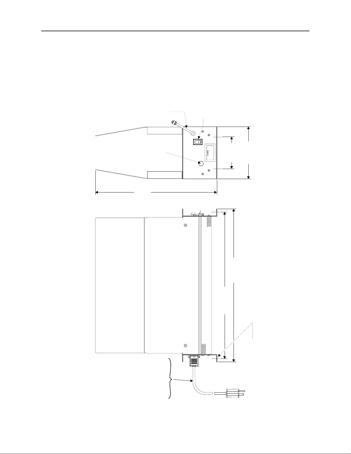
21-5/8”
(548 mm)
20-3/4”
(526 mm)
4-1/2”
(114 mm)
7-3/
8
”
(187 m
m
)
17-1/4”
(436 mm)
BA-300-115
7 ft. 0.5 in. (2.15 m)
LONG
BA-300-230
8 ft. 2 in. (2.49 m)
LONG
POWER CORD
(4) MTG. HOLES
CONTRO
L THERMO-
SWITCH
CABLE
(BA-310 O
NLY
)
INDICATOR
LIGHT
TOGG
L
E
SWITC
H
BLOWER
ON
MANUAL
AUTOMATIC
Figure 1
Outline Drawing
2
Page 13

Chapter 2 Theory of Operation
Loads convert RF energy into heat. This heat must be quickly
transferred to the surrounding environment to prevent damage to the
load. The coolant fluid surrounding the resistor transports the heat to
the radiator walls by convection. There, air passing over the radiator
fins carries the heat away.
When a load or attenuator is mounted on the Bird Blower Assembly,
baffles cover the radiator fins so that the high airflow generated by
two blower fans is confined to passing over the fins. Up to twice as
much RF energy can be dissipated by this forced draft air flow as
compared to normal convection air currents. Thus, a 2.5 kW load will
safely dissipate 5 kW using the Bird BA–300/310.
Power Rating
Reduction
The baffles interfere with the free flow of normal air currents, causing
a 50% reduction in heat transfer efficiency if the forced airflow is
stopped. Thus, a 2.5 kW load will have its maximum power
dissipation reduced to 1.25 kW.
3
Page 14

Bird BA–300/310 Blower Assembly
4
Page 15

Chapter 3 Installation
This chapter provides information for on-site requirements,
unpacking, inspection, and preparing the unit for use.
Unpacking and
Inspection
1. Carefully inspect the shipping container for signs of damage. If
damage is noticed, do not unpack the unit. Immediately notify the
shipping carrier and Bird Electronic Corporation.
2. If the container is not damaged, unpack the unit. Save the packing
materials in case the unit should need to be shipped again.
3. Inspect all of the components for visible signs of damage.
Immediately notify the shipping carrier and Bird Electronic
Corporation of equipment damage or missing parts.
Mounting Place the Blower Assembly in a dry, dust and vibration free environ-
ment. Do not use outdoors or in areas of condensing humidity. Allow
at least 3" (7.6 cm) of clearance above and on all sides of the unit.
CAUTION
The BA system is designed for operation in a horizontal position
only, with the load’s vent plug up. Do not use in any other manner.
Bird Blower Assemblies are equipped for either portable use or fixed
installation. The mounting brackets on the front and rear faces have
four mounting slots arranged in a 4
526.3 mm). Use a screw with a
3
⁄
" (9.53 mm) diameter max.
8
1
⁄
" x 20
2
23
⁄
" rectangle (114.3 x
32
5
Page 16

Bird BA–300/310 Blower Assembly
Installing
Thermoswitch
(BA–310 Only)
The Bird BA–310 requires a control thermoswitch, P/N 2450-085, for
automatic operation. It is normally open, closing at 155 °C (311 °F),
with a rating of 10A @ 120Vac and 5A @ 230Vac.
WARNING
Disconnect the unit from all power sources before servicing.
The unit may be energized from multiple sources.
The potential for electric shock exists.
WARNING
The vent plug must be used at all times when the load is
operating or cooling. Failure to do so could result in an
explosion or severe burns.
To install the thermoswitch on the load, proceed as follows:
1. Replace the vent plug in the load with the shipping plug.
2. Stand the load on its back with the connector end up. In this
position there is no danger of the coolant pouring out through the
socket plug hole.
3. Remove the top socket plug using a
9
⁄
" hex wrench.
16
4. Replace the plug with the thermoswitch. Sparingly apply pipe
sealing compound to the external threads, only, of the
thermoswitch. Do not contaminate the coolant with pipe sealant.
5. Check for coolant leaks upon completion.
6
Page 17
Installation
Thermoswitch
Connection
(BA–310 Only)
Connect the thermoswitch to the Bird BA–310 as follows :
CAUTION
If installed, connect optional interlock before applying RF power.
+ NOTE: If your unit has a connector already attached to the
thermoswitch cable, you do not need to perform Step 1 through
Step 4.
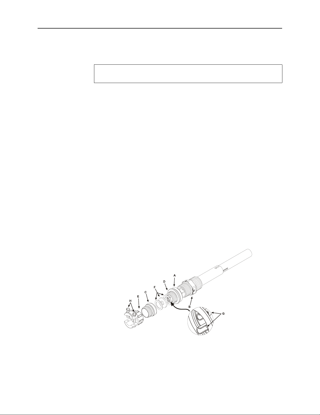
1. Unscrew the large knurled ring-nut (A) at the lower end of the
coupling jack assembly (See Figure 2 below). Pull it off the
thermoswitch jack (B). Unscrew the small knurled cover fitting
from the base plug (D) of the connector to release the base.
2. Thread the control switch wires through the clamp (E) with the
washers (F) inside and with its threaded fitting in place. Service
the control switch wire with short tips and put spaghetti sleeves
over the wire ends if necessary.
3. Securely solder the control switch leads to the lugs (G) of the
connector base.
+ NOTE: The ring-nut (A) must be in place over the base plug (D)
with the knurled end facing out.
Figure 2
Thermoswitch
Assembly
4. Screw on the cover ring, then fasten the cable clamp (E) in place
and tighten both yoke screws (H).
5. Put the plug back on the thermoswitch and tighten the nut (A).
7
Page 18

Bird BA–300/310 Blower Assembly
Load Resistor
To connect the Blower Assembly to a load, follow these instructions:
WARNING
Disconnect the unit from all power sources before servicing.
The unit may be energized from multiple sources.
The potential for electric shock exists.
WARNING
Do not operate with side panel removed.
y Remove one of the vertical panels by unscrewing both 10-32 truss
head screws.
y Place the load on the blower assembly against the remaining
vertical panel. Be sure that the RF input connector faces the same
direction as the blower control panel.
y Line up the base holes and loosely screw the load and blower
together with the nuts and screws provided.
y Remount the side panel and loosely replace the truss head screws.
y Line up the holes on the side panel tabs with those on the front
and rear faces of the load. Secure with four 10-32 truss head
screws.
AC Power Hookup
+ NOTE: It may be necessary to temporarily loosen the two screws
in the unremoved vertical panel.
y Tighten all the side panel and base mounting screws securely.
y Push the power cable’s plug into the socket at the rear of the
blower, then lock it in place with the clamp.
CAUTION
Check the local electrical code for proper ac hookup prior to
operation of the unit. Make sure the neutral or return hookup is
only used for that purpose.
WARNING
Turn off ac power and RF power when attaching the power cable.
The ac power supply required is 115/230 Vac, depending on the
model, @ 50/60 Hz, 1
(65 °C) ac inlet.
φ. The blower is equipped with an IEC 320 “cold”
8
Page 19

Chapter 4 Operating Instructions
CAUTION
The Bird BA–300/310 Blower Assembly will derate a load’s specified
power by 50% when installed and not running. If the indicator light
should turn off, immediately reduce RF power by at least 75%.
WARNING
Never attempt to connect or disconnect RF equipment from the
transmission line while RF power is being applied.
Leaking RF energy is a potential health hazard.
All Bird Blower Assemblies are equipped with a control switch and a
indicator light. No initial adjustments are required.
BA–300 Controls On the Bird BA–300, the switch is labelled “ON/OFF”. When the
switch is set to ON, the indicator light will turn on and the fans will
run continuously. When set to OFF, the indicator light will turn off
and the fans will not run.
BA–310 Controls On the Bird BA–310, the switch is labelled “MANUAL/
AUTOMATIC”. When the switch is set to MANUAL, the fans will run
continuously. When set to AUTOMATIC, the fans will be turned on
when the coolant reaches a preset temperature. The indicator light
will turn on whenever the unit is connected to ac power.
Normal Operation y Turn the blower on. Check that the indicator light is on.
+ NOTE: Set the Bird BA–310 to MANUAL momentarily to check
that the fans are working properly.
y Apply RF power.
Operation Under
Abnormal
Conditions
If the indicator light turns off or the fans stop unexpectedly,
immediately turn off the RF power or reduce it by at least 75% (half
of the load’s original power rating). Refer to “Troubleshooting” on
page 11 to correct the problem. The load can be subjected to higher
power levels for short intervals; refer to the load manual for details.
9
Page 20

Bird BA–300/310 Blower Assembly
Shutdown
Emergency
Shutdown
y Turn off RF power at the source.
y Wait approximately 15 minutes, or for the BA–310 fans to stop
running. This will allow the load to cool without causing heat
stress.
y Turn off the blower.
Turn off RF power at the source.
If the load is equipped with an interlock thermoswitch, RF power will
be automatically turned off when the coolant temperature reaches an
unsafe level. Use of an interlock thermoswitch is especially
recommended when using the blower assembly.
10
Page 21

Troubleshooting
Chapter 5 Maintenance
This chapter covers cleaning, inspection, troubleshooting, and
specifications for the Bird BA–300/310 Blower Assemblies.
WARNING
Never attempt to connect or disconnect RF equipment from the
transmission line while RF power is being applied.
Leaking RF energy is a potential health hazard.
WARNING
Disconnect the unit from all power sources before servicing.
The unit may be energized from multiple sources.
The potential for electric shock exists.
For corrections requiring repair or replacement of components see the
appropriate section. Only those functions within the scope of normal
maintenance are listed. This manual cannot list all malfunctions that
may occur, or corrective actions. If a problem is not listed or is not
corrected by the listed actions, notify a qualified service center.
Problem Possible Cause Possible Correction
No air flow from
blowers; indicator
light off
No air flow from
blowers; indicator
light on
Air flow from
blowers; indicator
light off
Unplugged power cable Connect the power cable
Fuse burnout Replace fuse after checking and correcting
the burnout cause. (See “Fuse” on page 13)
No ac power Make sure ac power is properly connected
and turned on
Fan obstructed by bent grill Straighten the grill
Fan motors overheated Clean the grill and fan blades (See
“Cleaning” on page 12)
Fan motors burnt out Replace the fan motors (See “Fan” on
page 14)
Lamp burnt out Replace the lamp (See “Indicator Light” on
page 13)
11
Page 22
Bird BA–300/310 Blower Assembly
Maintenance
Cleaning The intake grills, fan, and inside surface of the baffles should be
wiped free of dust and dirt when necessary with a clean soft cloth.
Excessive dust will interfere with the efficient dissipation of heat. If
the BA–300/310 has been standing without an installed load, check
for objects that may have entered the blower openings.
When a load is installed on the blower assembly, it will be necessary
to partially disassemble the blower to clean the load’s radiator fins.
Follow the instructions below:
WARNING
Disconnect the unit from all power sources before servicing.
The unit may be energized from multiple sources.
The potential for electric shock exists.
WARNING
Do not operate with side panel removed.
y Remove one of the side baffles by unscrewing both 10-32 truss
head screws.
y Clean the load.
y Screw the baffle back into place.
Inspection The only regular inspection required is to check for the accumulation
of dust in locations that might impede the free flow of air, i.e., intake
grill and fan blades. If the blower assembly is attached to a load,
clean the radiator fins regularly.
12
Page 23

Repair
Maintenance
WARNING
Disconnect the unit from all power sources before servicing.
The unit may be energized from multiple sources.
The potential for electric shock exists.
Fuse The fuse is located in the AC module on the back of the blower.
To replace the fuse:
y Correct the fuse burnout cause.
+ NOTE: Common causes include stuck or blocked fans or a short
circuit in the motor or blower wiring.
y Press the locking tab on the fuse drawer and remove the drawer.
y Replace the fuse. See “Specifications” on page 17 for fuse type and
current rating.
y Push the drawer into the AC module until it locks into place.
y If the fans still do not run or if the fuse burns out again, return
the blower assembly to the factory.
Indicator Light 1. Remove the four 8-32 pan head screws from the front and back of
the base frame.
2. Pull the fan guard straight off the bottom.
3. Remove the quick disconnects on the light and unscrew the
retaining sleeve.
4. Remove the light unit.
5. Remove the lens while pressing both locking tabs.
6. Press the housing’s center slot with a small screwdriver to release
the lamp.
7. Push the new lamp into the housing until it snaps into place.
8. Replace the lens, then put the light unit back in place.
9. Replace the fan guard and screw in the 8-32 pan head screws.
13
Page 24
Bird BA–300/310 Blower Assembly
L1
L2
L1
L2
ROTATION
FANS
N L
GRN/YEL
AC
RECEPTACLE
WHT/YEL
TOGGLE
SWITCH
WHT/BLK
W
H
T
/
B
L
K
INDICATOR
LIGHT
WHT/BLK
Fan
To replace a fan assembly:
WARNING
Disconnect the unit from all power sources before servicing.
The unit may be energized from multiple sources.
The potential for electric shock exists.
1. Remove the four 8-32 pan head screws from the front and back of
the base frame.
2. Pull the fan guard straight off the bottom.
3. Carefully unsolder the color coded connecting wires. Note the
connections for resoldering.
4. Remove the four fan mounting screws and remove the defective
fan. Be careful not to lose the lipped retaining washers.
5. Insert the replacement fan with the fan blade assembly facing
down, towards the fan guard grill.
6. Insert the mounting screws and retaining washers into the
mounting holes. Turn the washers so that the lipped portion fits
over the rim of the fan frame. Tighten the screws.
+ NOTE: If the fan replaced is the one closest to the power socket,
reattach the green ground wire to the closest mounting screw.
7. Solder the connecting wires to the solder lugs on the motor unit
according to the color coding.
8. Replace the fan guard and screws.
+ NOTE: Before reattaching the blower assembly to the load, check
the fans for free and unimpeded movement of the blades.
9. Connect the unit to ac power. Set the switch to MANUAL or ON
momentarily to check that the fans work properly.
Figure 3
BA–300
Schematic
14
Page 25

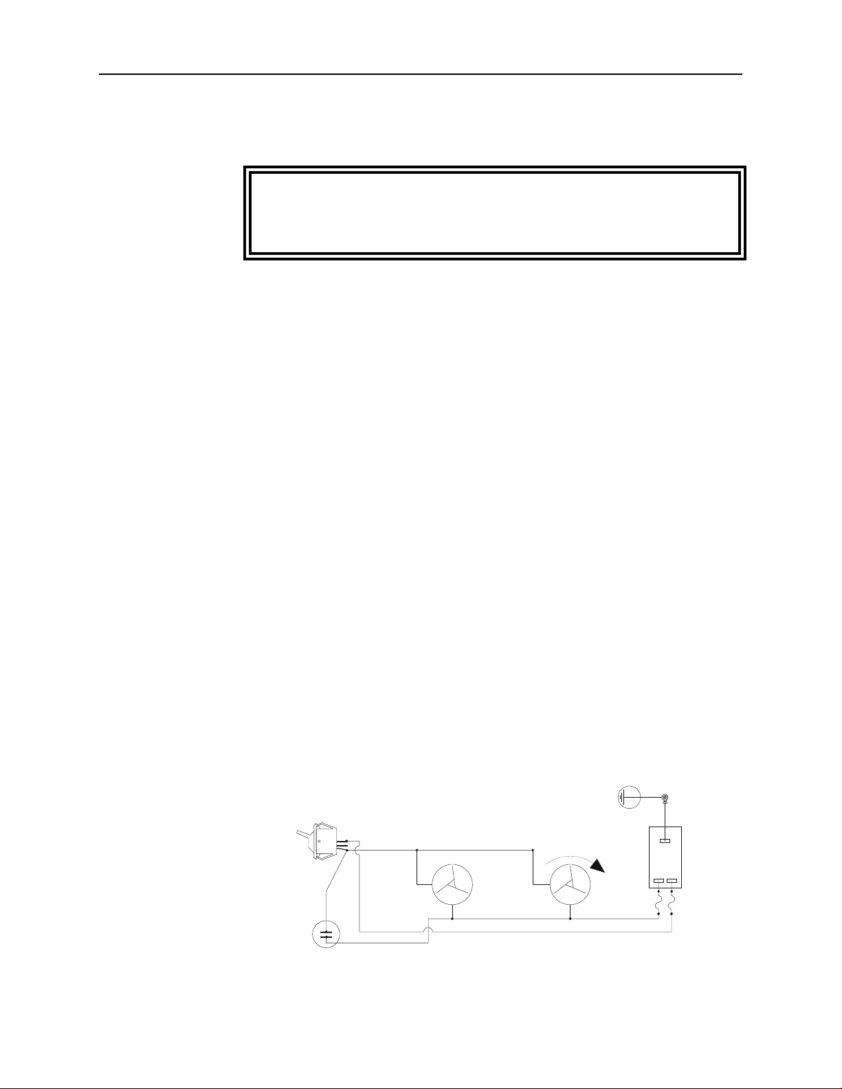
Figure 4
N L
L1
L2
L1
L2
ROTATION
FANS
GRN/YEL
AC
RECEPTACLE
WHT/YEL
TO CONTROL
THERMOSWITCH
BLACK
RED
TOGGLE
SWITCH
WHT/BLK
WHT/BLK
INDICATOR
LIGHT
WHT/BLK
BA–310
Schematic
Maintenance
15
Page 26

Bird BA–300/310 Blower Assembly
Storage and Shipment
Cover the Bird BA–300/310 before storing to keep out dust and dirt.
Store in a dry, dust-free environment where the ambient temperature
will remain between –40 and +45 °C (–40 to +113 °F).
To ship the blower assembly, take the following precautions:
y Detach the power cable and tape it securely to the housing.
y To ship the blower assembly by itself, pack it in a sturdy
corrugated paper shipping carton. If it is attached to a load, a
wood crate is recommended because of size and weight.
Customer Service
Any maintenance or service procedure beyond the scope of those in
this chapter should be referred to a qualified service center.
If you need to return the unit for any reason, contact the Bird Service
Center for a return authorization. All instruments returned must be
shipped prepaid and to the attention of Bird Service Center.
Bird Service Center
30303 Aurora Road
Cleveland (Solon), Ohio 44139-2794
Phone: (440) 519-2298
Fax: (440) 519-2326
For the location of the sales office nearest you, give us a call or visit
our Web site at:
http://www.bird-electronic.com
16
Page 27

Specifications
Maintenance
AC Power Requirements:
115 Vac
230 Vac
Fuse Rating
115 Vac
230 Vac
Thermoswitch
Thermoswitch Rating
115 Vac
230 Vac
Temperature
Humidity
Dimensions
*
Weight, Nominal
Finish
* 22" H (560 mm) with load in place
0.6 A @ 50/60 Hz
0.3 A @ 50/60 Hz
IEC (5 x 20 mm) Type T
1 A
500 mA
Normally open. Closes at 155 °C (311 °F)
10 A
5 A
–40 to +113 °F (–40 to +45 °C)
95% non-condensing max
215⁄8" L x 73⁄8" W x 171⁄4" H
(548 x 187 x 436 mm)
13.5 lb (6.1 kg)
Grey Powder Coat
17
Page 28

Bird BA–300/310 Blower Assembly
Replacement Parts
DESCRIPTION QTY PART NUMBER
Control Thermoswitch (BA–310 only) 1 2450-085
Side Panel Screws
(10-32 x
Radiator Base Mounting Screws
3
⁄8-16 x 3⁄4" hex head)
(
3
⁄8" phillips truss head)
Fuse 5x20mm Type T
1 A, 115 Vac
500 mA, 230 Vac
4 1120-0619-00
4 1124-1207-00
2
5A2257-16
5A2257-13
Fuse Drawer 1 5A2310
Power Cable
115 Vac
230 Vac
Lamp
115 Vac
230 Vac
1
5-1286
5A2416
1
5A2409-1
5A2409-2
Fan Guard 1 8950-306-1
Fan
115 Vac
230 Vac
2
5A383
5A381
Toggle Switch 1 5A2312
18
Page 29

Limited Warranty
All products manufactured by Seller are warranted to be free from defects in
material and workmanship for a period of one (1) year, unless otherwise
specified, from date of shipment and to conform to applicable specifications,
drawings, blueprints and/or samples. Seller’s sole obligation under these
warranties shall be to issue credit, repair or replace any item or part thereof
which is proved to be other than as warranted; no allowance shall be made for
any labor charges of Buyer for replacement of parts, adjustment or repairs, or
any other work, unless such charges are authorized in advance by Seller.
If Seller’s products are claimed to be defective in material or workmanship or not
to conform to specifications, drawings, blueprints and/or samples, Seller shall,
upon prompt notice thereof, either examine the products where they are located
or issue shipping instructions for return to Seller (transportation-charges
prepaid by Buyer). In the event any of our products are proved to be other than
as warranted, transportation costs (cheapest way) to and from Seller’s plant, will
be borne by Seller and reimbursement or credit will be made for amounts so
expended by Buyer. Every such claim for breach of these warranties shall be
deemed to be waived by Buyer unless made in writing within ten (10) days from
the date of discovery of the defect.
The above warranties shall not extend to any products or parts thereof which
have been subjected to any misuse or neglect, damaged by accident, rendered
defective by reason of improper installation or by the performance of repairs or
alterations outside of our plant, and shall not apply to any goods or parts thereof
furnished by Buyer or acquired from others at Buyer’s request and/or to Buyer’s
specifications. Routine (regularly required) calibration is not covered under this
limited warranty. In addition, Seller’s warranties do not extend to the failure of
tubes, transistors, fuses and batteries, or to other equipment and parts
manufactured by others except to the extent of the original manufacturer’s
warranty to Seller.
The obligations under the foregoing warranties are limited to the precise terms
thereof. These warranties provide exclusive remedies, expressly in lieu of all
other remedies including claims for special or consequential damages. SELLER
NEITHER MAKES NOR ASSUMES ANY OTHER WARRANTY WHATSOEVER, WHETHER EXPRESS, STATUTORY, OR IMPLIED, INCLUDING
WARRANTIES OF MERCHANTABILITY AND FITNESS, AND NO PERSON
IS AUTHORIZED TO ASSUME FOR SELLER ANY OBLIGATION OR
LIABILITY NOT STRICTLY IN ACCORDANCE WITH THE FOREGOING.
 Loading...