

Page 1

INSTRUCTION BOOK
Operator Manual
AT-800 Antenna Tester
© Copyright 2009 by Bird Electronic Corporation
Instruction Book Part Number 920-AT800 Rev N
Page 2

Page 3

Safety Precautions
The following are general safety precautions that are
not necessarily related to any specific part or proce
dure, and do not necessarily appear elsewhere in this
publication. These precautions must be thoroughly
understood and apply to all phases of operation and
maintenance.
WARNING
Keep Away From Live Circuits
Operating Personnel must at all times observe
general safety precautions. Do not replace
components or make adjustments to the inside of the
test equipment with the high voltage supply turned
on. To avoid casualties, always remove power.
WARNING
Shock Hazard
Do not attempt to remove the RF transmission line
while RF power is present.
-
WARNING
Do Not Service Or Adjust Alone
Under no circumstances should any person reach
into an enclosure for the purpose of service or
adjustment of equipment except in the presence of
someone who is capable of rendering aid.
ii
Page 4
Bird AT-800 Antenna Tester
WARNING
Safety Earth Ground
An uniterruptible earth safety ground must be
supplied from the main power source to test
instruments. Grounding one conductor of a two
conductor power cable is not sufficient protection.
Serious injury or death can occur if this grounding is
not properly supplied.
WARNING
Resuscitation
Personnel working with or near high voltages
should be familiar with modern methods of
resuscitation.
Safety Symbols
WARNING
Warning notes call attention to a procedure, which
if not correctly performed, could result in personal
injury.
CAUTION
Caution notes call attention to a procedure, which if
not correctly performed, could result in damage to
the instrument.
The caution symbol appears on the equipment indicating there is important information in the instruction manual regarding
tha
t particular area
Note: Calls attention to supplemental
information.
iii
Page 5

Warning Statements
The following safety warnings appear in the text
where there is danger to operating and maintenance
personnel, and are repeated here for emphasis.
WARNING
Care should be taken when handling batteries.
Do not heat or dispose of batteries in fire. May burst or
release toxic materials.
Avoid forced discharge.
Do not short circuit.
Restrict charging current and time to the
recommended value.
Do not solder the battery directly.
Do not disassemble, apply excessive pressure or deform.
Avoid placing the battery in reverse polarity.
Battery disposal method should be in accordance with
local and state regulations.
On page41.
WARNING
Replace with ONLY Nickel-Metal hydride (NiMH)
rechargeable AA batteries with a nominal voltage of
1.2V and minimum capacity of 2000mAh. DO NOT
install any type of battery such as alkaline or other
type of secondary (chargeable) batteries.
On page 46.
WARNING
Charging batteries installed in reverse polarity can
cause the battery to swell or rupture.
On page 47.
iv
Page 6

Bird AT-800 Antenna Tester
Caution Statements
The following equipment cautions appear in the text
whenever the equipment is in danger of damage and
are repeated here for emphasis.
CAUTION
Follow guidelines for battery charging.
Avoid constant charging of batteries for long periods
of time. Overcharging can result in reduced battery
efficiency, service life, and possible permanent
damage.
On page 15 and 42.
CAUTION
Required input is 11 to 16 VDC @ 250mA. Connector
is wired outside positive, inside negative.
On page 16.
CAUTION
AVOID STATIC DISCHARGE
Use proper Electrostatic Discharge (ESD)
precautions to avoid static discharge when making
connections to the test port. Equipment failure can
occur if the test port is subjected to ESD.
On page 17.
v
Page 7

CAUTION
250mW max. input
Exceeding the maximum input will cause damage to
internal components. Do not connect transmitter
output to the AT-800. Damage can also be caused by
testing antennas near other transmitting antennas. If
testing base station antennas, first measure the power
at the coax end to be sure it does not exceed 250mW.
On page 17.
CAUTION
Harsh or abrasive detergents and some solvents can
damage the display unit and information on labels.
On page 41.
CAUTION
Replace with only the same type and rating fuse.
315mA 250V
On page 48.
vi
Page 8

Bird AT-800 Antenna Tester
Safety Statements
USAGE
ANY USE OF THIS INSTRUMENT IN A MANNER
NOT SPECIFIED BY THE MANUFACTURER MAY
IMPAIR THE INSTRUMENT’S SAFETY
PROTECTION.
USO
EL USO DE ESTE INSTRUMENTO DE MANERA
NO ESPECIFICADA POR EL FABRICANTE, PUEDE
ANULAR LA PROTECCIÓN DE SEGURIDAD DEL
INSTRUMENTO.
BENUTZUNG
WIRD DAS GERÄT AUF ANDERE WEISE
VERWENDET ALS VOM HERSTELLER
BESCHRIEBEN, KANN DIE GERÄTESICHERHEIT
BEEINTRÄCHTIGT WERDEN.
UTILISATION
TOUTE UTILISATION DE CET INSTRUMENT QUI
N’EST PAS EXPLICITEMENT PRÉVUE PAR LE
FABRICANT PEUT ENDOMMAGER LE
DISPOSITIF DE PROTECTION DE
L’INSTRUMENT.
IMPIEGO
QUALORA QUESTO STRUMENTO VENISSE
UTILIZZATO IN MODO DIVERSO DA COME
SPECIFICATO DAL PRODUTTORE LA PROZIONE
DI SICUREZZA POTREBBE VENIRNE
COMPROMESSA.
vii
Page 9

SERVICE
SERVICING INSTRUCTIONS ARE FOR USE BY
SERVICE - TRAINED PERSONNEL ONLY. TO AVOID
DANGEROUS ELECTRIC SHOCK, DO NOT PERFORM
ANY SERVICING UNLESS QUALIFIED TO DO SO.
SERVICIO
LAS INSTRUCCIONES DE SERVICIO SON PARA
USO EXCLUSIVO DEL PERSONAL DE SERVICIO
CAPACITADO. PARA EVITAR EL PELIGRO DE
DESCARGAS ELÉCTRICAS, NO REALICE NINGÚN
SERVICIO A MENOS QUE ESTÉ CAPACITADO
PARA HACERIO.
WARTUNG
ANWEISUNGEN FÜR DIE WARTUNG DES
GERÄTES GELTEN NUR FÜR GESCHULTES
FACHPERSONAL.
ZUR VERMEIDUNG GEFÄHRLICHE, ELEKTRISCHE
SCHOCKS, SIND WARTUNGSARBEITEN
AUSSCHLIEßLICH VON QUALIFIZIERTEM
SERVICEPERSONAL DURCHZUFÜHREN.
ENTRENTIEN
L’EMPLOI DES INSTRUCTIONS D’ENTRETIEN
DOIT ÊTRE RÉSERVÉ AU PERSONNEL FORMÉ
AUX OPÉRATIONS D’ENTRETIEN. POUR
PRÉVENIR UN CHOC ÉLECTRIQUE DANGEREUX,
NE PAS EFFECTUER D’ENTRETIEN SI L’ON N’A
PAS ÉTÉ QUALIFIÉ POUR CE FAIRE.
ASSISTENZA TECNICA
LE ISTRUZIONI RELATIVE ALL’ASSISTENZA
SONO PREVISTE ESCLUSIVAMENTE PER IL
PERSONALE OPPORTUNAMENTE ADDESTRATO.
PER EVITARE PERICOLOSE SCOSSE ELETTRICHE
NON EFFETTUARRE ALCUNA RIPARAZIONE A
MENO CHE QUALIFICATI A FARLA.
viii
Page 10

Bird AT-800 Antenna Tester
UNITS ARE EQUIPPED WITH RECHAREABLE
BATTERIES.
THESE ARE TO BE REPLACED BY AUTHORIZED
SERVICE PERSONNEL ONLY!!!
LAS UNIDADES VIENEN EQUIPADAS CON
BATERIAS RECARGABLES.
¡¡¡Y SOLAMENTE EL PERSONAL DE SERVICIO
AUTORIZADO PUEDE REEMPLAZARLAS!!!
GERÄTE SIND MIT WIEDER AUFLADBAREN
BATTERIEN BESTÜCKT.
BATTERIEN SIND NUR VON QUALIFIZIERTEM
SERICE PERSONAL AUSZUWECHSELN!!!
CES DISPOSITIFS SONT ÉQUIPÉS DE BATTERIES
RECHARGEABLES.
SEUL LE PERSONNEL D’ENTRETIEN AUTORISÉ
EST HABILITÉ À LES REMPLACER !
LE UNITÀ SONO DOTATE DI BATTERIE
RICARICABILI,
CHE DEVONO DA COME SPECIFICATO DAL
PRODUTTORE LA PROTEZIONE DI SICUREZZA
POTREBBE VENIRNE COMPROMESSA.
ix
Page 11

RF VOLTAGE MAY BE PRESENT IN RF ELEMENT
SOCKET - KEEP ELEMENT IN SOCKET DURING
OPERATION.
DE LA TENSION H.F. PEAT ÊTRE PRÉSENTE DANS
LA PRISE DE L'ÉLÉMENT H.F. - CONSERVER
L'ÉLÉMENT DANS LA PRISE LORS DE L'EMPLOI.
HF-SPANNUNG KANN IN DER HF-ELEMENTBUCHSE ANSTEHEN - ELEMENT WÄHREND DES
BETRIEBS EINGESTÖPSELT LASSEN.
PUEDE HABER VOLTAJE RF EN EL ENCHUFE DEL
ELEMENTO RF - MANTENGA EL ELEMENTO EN EL
ENCHUFE DURANTE LA OPERACION.
IL PORTAELEMENTO RF PUÒ PRESENTARE
VOLTAGGIO RF - TENERE L'ELEMENTO NELLA
PRESA DURANTE IL FUNZIONAMENTO.
x
Page 12

Bird AT-800 Antenna Tester
About This Manual
This manual covers the operating and maintenance
instructions for the following models:
AT-800
Changes to this Manual
We have made every effort to ensure this manual is
accurate. If you discover any errors, or if you have sug
gestions for improving this manual, please send your
comments to our Solon, Ohio factory. This manual
may be periodically updated. When inquiring about
updates to this manual refer to the part number and
revision on the title page.
Typography
There are two types of keys on the Antenna Tester. A
Hard Key is a key that has a particular function and it
is indicated on the key. These key names are set in a
bold typeface, e.g. Press the MENU key.
-
A Menu Select Key, (there are five under the display),
will have a different label, or name, depending on the
selected function. The name will be at the bottom of
the display located directly above the corresponding
key. These key names are set in a bold Italic typeface,
e.g. Press the MEAS MATCH key.
xi
Page 13

Chapter Layout
Introduction—Will help you become familiar with
the parts of the Antenna Tester, Features Available,
and Optional Equipment.
Basic Operation—Everyone should read this section!
This section provides information to get the Antenna
Tester powered up, helpful information about how to
operate the Antenna Tester, and time saving hints for
alternate operating methods.
Installation—This chapter contains the information
on how to connect the AT-800 to antenna systems, and
to power sources to charge and operate the unit.
Measure Match—Since the AT-800 Antenna Tester
offers a unique method of measuring Antenna Systems
we have included the section, “Understanding the
Operating Modes.” Even if you already know the
basics of antenna match testing you might find this
section useful. The remainder of the chapter provides
step by step instructions for measuring match.
Field Strength—This chapter provides step by step
instructions for measuring relative field strength of
fixed cellular antennas.
Maintenance—This chapter contains the information
required to keep the AT-800 working for you. This
includes battery and fuse information, troubleshooting
information, parts lists, and specifications.
xii
Page 14

Table of Contents
Safety Precautions . . . . . . . . . . . . . . . . . . . . . . . . . ii
Safety Symbols . . . . . . . . . . . . . . . . . . . . . . . . . . . iii
Warning Statements . . . . . . . . . . . . . . . . . . . . . . . iv
Caution Statements . . . . . . . . . . . . . . . . . . . . . . . . v
Safety Statements . . . . . . . . . . . . . . . . . . . . . . . . .vii
About This Manual . . . . . . . . . . . . . . . . . . . . . . . . . xi
Changes to this Manual . . . . . . . . . . . . . . . . . . . . xi
Typography . . . . . . . . . . . . . . . . . . . . . . . . . . . xi
Chapter Layout . . . . . . . . . . . . . . . . . . . . . . . . xii
Chapter 1 Introduction . . . . . . . . . . . . . . . . . . . . . . 1
Items Supplied . . . . . . . . . . . . . . . . . . . . . . . . . . . . 1
Component Description . . . . . . . . . . . . . . . . . . . . . 2
Display Description . . . . . . . . . . . . . . . . . . . . . . . . . 4
Features . . . . . . . . . . . . . . . . . . . . . . . . . . . . . . . . . . 6
Swept Frequency Mode . . . . . . . . . . . . . . . . . . . 6
Single Frequency Mode . . . . . . . . . . . . . . . . . . . 6
Auto Scaling . . . . . . . . . . . . . . . . . . . . . . . . . . . . 6
Relative Field Strength . . . . . . . . . . . . . . . . . . . 6
Cellular System Presets . . . . . . . . . . . . . . . . . . 6
Limit Testing . . . . . . . . . . . . . . . . . . . . . . . . . . . 6
Data Storage . . . . . . . . . . . . . . . . . . . . . . . . . . . 6
Serial Communication Link . . . . . . . . . . . . . . . 6
Optional Equipment . . . . . . . . . . . . . . . . . . . . . . . . 7
Automobile Cigarette
Lighter Adapter Cable (P/N 5A2238-1) . . . . . . 7
Carrying Case (P/N 5000-030) . . . . . . . . . . . . . 7
Verification Kit (P/N 7000A845) . . . . . . . . . . . . 7
Interface Software (P/N 7000B840) . . . . . . . . . 7
xiii
Page 15

Chapter 2 Basic Operations . . . . . . . . . . . . . . . . . . 9
Getting Started . . . . . . . . . . . . . . . . . . . . . . . . . . . . 9
Messages . . . . . . . . . . . . . . . . . . . . . . . . . . . . . 11
Out of Range Values . . . . . . . . . . . . . . . . . . . . 12
Selecting the Cellular System . . . . . . . . . . . . . 12
Setting the Auto Shut-Off Timer . . . . . . . . . . 12
Return to Factory Presets . . . . . . . . . . . . . . . . 13
Set Serial Baud Rate . . . . . . . . . . . . . . . . . . . . 14
Chapter 3 Installation . . . . . . . . . . . . . . . . . . . . . . 15
Power Supply . . . . . . . . . . . . . . . . . . . . . . . . . . . . 15
AC Mains Adapter . . . . . . . . . . . . . . . . . . . . . . 16
Automobile Cigarette
Lighter Adapter Cable . . . . . . . . . . . . . . . . . . . 16
Connecting the Antenna . . . . . . . . . . . . . . . . . . . . 17
Chapter 4 Measure Match . . . . . . . . . . . . . . . . . . 19
Understanding the Operating Modes . . . . . . . . .19
Swept Frequency vs.
Single Frequency . . . . . . . . . . . . . . . . . . . . . . . 19
Band Selection Presets vs.
User Defined . . . . . . . . . . . . . . . . . . . . . . . . . . 20
Measurement Units 20
Auto Scale vs.
Manual Scale . . . . . . . . . . . . . . . . . . . . . . . . . . 22
Sweep Type – Single Hold vs.
Continuous . . . . . . . . . . . . . . . . . . . . . . . . . . . . 23
Swept Frequency . . . . . . . . . . . . . . . . . . . . . . . . . . 24
Select Frequency Band - Presets . . . . . . . . . . 24
Select Frequency Band - User Defined . . . . . . 24
Select Measurement Units . . . . . . . . . . . . . . . 26
Select Auto or Manual Scale . . . . . . . . . . . . . . 26
Selecting the Sweep Type . . . . . . . . . . . . . . . . 28
Saving a Trace . . . . . . . . . . . . . . . . . . . . . . . . . . . . 28
Recalling a Trace . . . . . . . . . . . . . . . . . . . . . . . . . 30
Clearing a Trace . . . . . . . . . . . . . . . . . . . . . . . . . . 31
xiv
Page 16

Limit Testing . . . . . . . . . . . . . . . . . . . . . . . . . . . . . 31
Turn Audio On/Off . . . . . . . . . . . . . . . . . . . . . . 32
Selecting Limit Values . . . . . . . . . . . . . . . . . . 32
Using a Trace as the Limit . . . . . . . . . . . . . . . 33
Clearing a Limit . . . . . . . . . . . . . . . . . . . . . . . . 34
Single Frequency . . . . . . . . . . . . . . . . . . . . . . . . . 35
Selecting the Frequency -
User Defined . . . . . . . . . . . . . . . . . . . . . . . . . . 35
Selecting the Frequency -
Automatically . . . . . . . . . . . . . . . . . . . . . . . . . . 35
Select Measurement Units . . . . . . . . . . . . . . . 36
Select Auto or Manual Scale . . . . . . . . . . . . . . 36
Turn Audio On/Off . . . . . . . . . . . . . . . . . . . . . . 37
Chapter 5 Field Strength . . . . . . . . . . . . . . . . . . .39
Field Strength Measurement . . . . . . . . . . . . . . . 39
Turn Audio On/Off . . . . . . . . . . . . . . . . . . . . . 39
Enter Gain Factor /
Select Auto Gain . . . . . . . . . . . . . . . . . . . . . . . 39
Chapter 6 Maintenance . . . . . . . . . . . . . . . . . . . . . 41
Cleaning . . . . . . . . . . . . . . . . . . . . . . . . . . . . . . . . 41
Calibration . . . . . . . . . . . . . . . . . . . . . . . . . . . . . . 41
Charging Batteries . . . . . . . . . . . . . . . . . . . . . . . . 41
Batteries and Long Term Storage . . . . . . . . . . . . 42
Operational Tests . . . . . . . . . . . . . . . . . . . . . . . . . 43
Power-up . . . . . . . . . . . . . . . . . . . . . . . . . . . . . 43
Battery Test . . . . . . . . . . . . . . . . . . . . . . . . . . . 43
Display Test . . . . . . . . . . . . . . . . . . . . . . . . . . . 44
Self Test . . . . . . . . . . . . . . . . . . . . . . . . . . . . . . 45
Battery Replacement . . . . . . . . . . . . . . . . . . . . . . 46
Fuse Replacement . . . . . . . . . . . . . . . . . . . . . . . . . 48
xv
Page 17

Troubleshooting . . . . . . . . . . . . . . . . . . . . . . . . . . 49
The Antenna Tester
will not power up . . . . . . . . . . . . . . . . . . . . . . . 49
NVRAM Test Fails . . . . . . . . . . . . . . . . . . . . . 49
ROM, EEPROM, RAM, A/D,
TEMPR, PLL Test Fails . . . . . . . . . . . . . . . . . 49
Stuck Keys Test Fails . . . . . . . . . . . . . . . . . . . 50
“Noise” is Displayed
During Testing . . . . . . . . . . . . . . . . . . . . . . . . . 50
Antenna Tester indicates
a Perfect Match . . . . . . . . . . . . . . . . . . . . . . . . 50
Customer Service . . . . . . . . . . . . . . . . . . . . . . . . . 51
Parts List . . . . . . . . . . . . . . . . . . . . . . . . . . . . . . . . 52
Specifications . . . . . . . . . . . . . . . . . . . . . . . . . . . . 53
Menu Structure . . . . . . . . . . . . . . . . . . . . . . . . . . . 55
Limited Warranty . . . . . . . . . . . . . . . . . . . . . . . . . 56
xvi
Page 18

xvii
Page 19
Chapter 1 Introduction
4
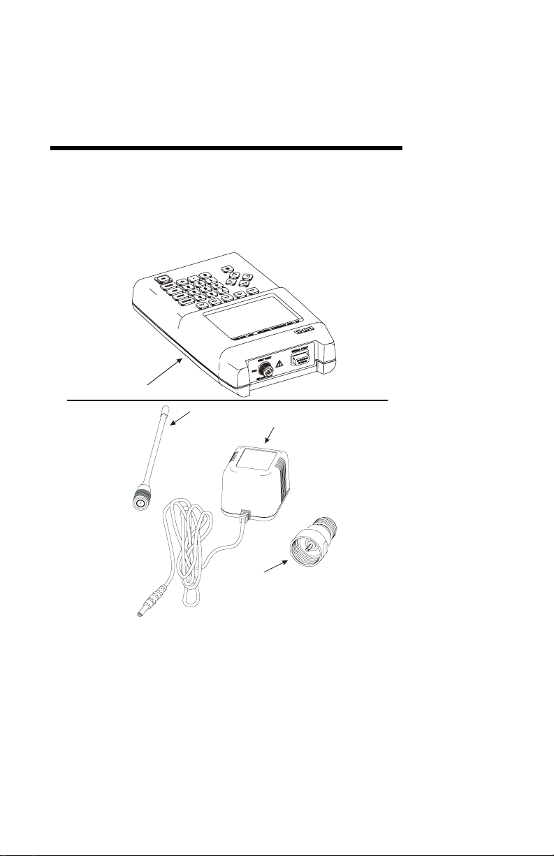
Items Supplied
Figure 1 Supplied Items
1
2
1. Bird AT-800
2. AC Mains Adapter
3. Female TNC Connector
4. Field Strength Antenna
5. Instruction Book (not shown)
3
1
Page 20
Bird AT-800 Antenna Tester
0
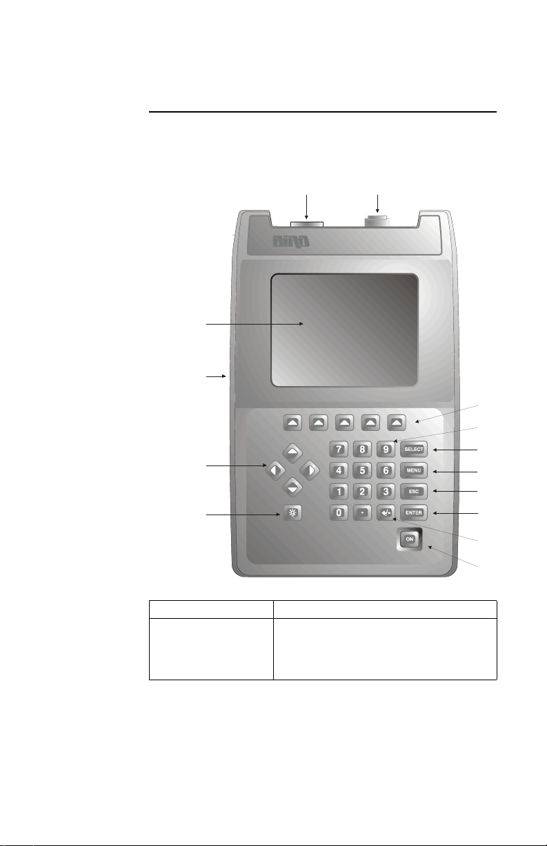
Component Description
Figure 2 Component Description
1
2
3
4
1314
12
11
1
9
8
7
1. LCD Display Backlit liquid crystal display.
2. External DC
Connector
Connect either the ac adapter or the
cigarette lighter adapter cable. External
supplies operate the unit and charge
the internal battery.
2
6
5
Page 21

Introduction
3. Cursor Keys
Left Arrow Press in swept frequency mode to
move the cursor to the left. Press during
data entry to erase data.
Right Arrow Press in swept frequency mode to
move the cursor to the right.
Up Arrow Moves the cursor to the maximum point
on the displayed trace. Press during
data entry to increase numeric data.
Down Arrow Moves the cursor to the minimum point
on the displayed trace. Press during
data entry to decrease numeric data.
4. Backlight Key Turns the backlight on or off. Backlight
is on a timer to increase battery life.
5. On Key Press to turn tester on, press and hold
to turn tester off.
6. +/- Key Toggles between positive and negative
numbers.
7. Enter Key Completes data entry.
8. ESC Key Back up through menu structure. At the
top menu level, blanks menu. Exits data
entry without saving changes.
9. Menu Key Displays software menu and enables
menu select keys.
10. Select Key Allows current parameter, indicated by
flashing cursor, to be changed. Press
again to enable the next parameter to
be changed.
11. Numeric Keys Input numeric values.
12. Menu Select
Keys
Used to access the menu sections
described directly above them. Can
also be used to scroll through available
settings in a particular parameter.
13. Test Port Connect antenna or antenna lead.
14. Serial Port Connect communication cable to allow
data transfer to a PC.
3
Page 22
Bird AT-800 Antenna Tester
111213
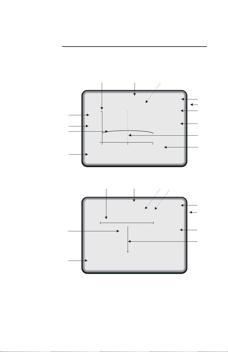
Display Description
Figure 3 Display Description
1.35
2.0
1
2
*
VSWR
858.27 MHz
AMPS
Mobile
TxRx
Busy
3
1.0
824.01 MHz 893.97
4
Meas
Match
2
1.2
Field
Str
1.35
858.27 MHz CH 345
VSWR
Util Test
111213
15
AMPS
Mobile
1.5
Low
Batt
10
9
8
7
6
5
10
9
7
14
4
Freq
MHz
Units Manual
Scale
Auto
Scale
Audio
Off
4
Page 23

Introduction
1. Sweep Rate
Blinks when sweeping.
Indicator
2. Measurement Units Indicates selected measurement
units.
3. Trace Graphic display of measured
results across selected frequency
band.
4. Menu Select Key
Labels
5. Frequency Band
Defines function of menu select
keys located below the display.
Displays frequency band selected.
Scale
6. Cursor Used to select measurement
position on the trace.
7. Utility Label Area for displaying general data
(Lo Batt, Busy, Hold, Noise, and
test results).
8. Band Indicates selected band for cellular
system defined, (Tx, Rx, TxRx, or
User).
9. Base/Mobile
Indicates Base or Mobile selection.
Indicator
10. Cellular System Indicates cellular system selected
(AMPS, GSM, PDC, CT-2, CT-2
Korea).
11. Frequency Selected Frequency (for swept
mode this is frequency at the
cursor position).
12. Measured Value Numeric display of measured value
(for swept mode this is the value at
the cursor position).
13. Scale Displays user defined
measurement scale.
14. Pointer Moves across scale to show
analog indication of measured
value.
15. Channel Channel number corresponding to
selected frequency.
5
Page 24

Bird AT-800 Antenna Tester
Features
Swept Frequency Mode
Fast scan shows Voltage Standing Wave Ratio
(VSWR); Reflection Coefficient (
Loss (dB) across an entire band. A movable cursor can
be used to pinpoint a scan frequency and the corre
sponding measurement value is displayed.
Single Frequency Mode
Provides measurement information in units of VSWR,
ρ, match efficiency or return loss at one frequency on a
simulated meter movement. An audio generator can
be enabled to produce a tone that is proportional to the
match condition.
Auto Scaling
Used in either swept or single frequency modes, sets
the Y axis for best measurement display.
Relative Field Strength
Verifies output of portable cellular phones with fixed
antennas.
Cellular System Presets
Pre-programmed band segments for AMPS, GSM,
PDC, CT-2, and CT-2 Korea cellular testing.
ρ); % Match, or Return
-
Limit Testing
Quick pass-fail indication; compares measurements to
user selected limits.
Data Storage
Saves and recalls up to 12 traces to be used to set limit
or long term monitoring of antenna performance.
Serial Communication Link
Built in serial port and optional software uploads data
to a personal computer for analysis or storage.
6
Page 25

Introduction
Optional Equipment
Automobile Cigarette Lighter Adapter Cable (P/N 5A2238-1)
Connects tester to standard 12V automotive cigarette
lighter jack.
Carrying Case (P/N 5000-030)
Convenient and protective, large enough to carry the
tester, AC adapter, connectors, field strength antenna
and instruction book.
Verification Kit (P/N 7000A845)
Used to verify tester performance. Includes standard
mismatch and connector adapter.
Interface Software (P/N 7000B840)
PC software used to upload trace data for analysis,
printing or storage.
Note: System requirements: IBM PC or
equivalent; Windows 95 or later, 6 MB free
hard disk space; VGA monitor, open com port.
Includes interface cable.
7
Page 26

Bird AT-800 Antenna Tester
8
Page 27

Chapter 2 Basic Operations
Getting Started
This section describes initial quick steps to get started. For
detailed information regarding connecting the Antenna
Tester refer to
ON
Power On/Off
z To turn the Antenna Tester on, momentarily
z To turn the Antenna Tester off, press and hold
Backlight
"Connecting the Antenna" on page 17
Note: This unit is shipped with the batter-
ies not charged. Charge batteries for at least 8
hours before use.
press the ON key. The results of a self test will
be displayed if a failure is present. For more
information about the self test or a failure,
refer to "Maintenance" on page 41.
the ON key for 1 second.
z To turn the backlight on, press the
BACKLIGHT key.
z To increase or decrease display contrast, press
and hold the BACKLIGHT key while pressing
either the UP or DOWN arrow key.
z To turn the backlight off, press the
BACKLIGHT key.
9
Page 28

Bird AT-800 Antenna Tester
Software Menu
MENU
z Press the MENU key to display the software
menu.
Blinking Cursor (black square)
The cursor will be blinking in the selected area, indicating that the parameter for that area can be changed.
Enter Key
ENTER
All data entry, and mode changes accessed using select
key, require the enter key to be pressed before they are
initiated.
Up/Down Arrow Keys
When a function is enabled for change, the UP or
DOWN arrow keys can be used to either scroll through
choices or increase/decrease the numerical value. The
actual increments depend on the function.
Left Arrow Key
The LEFT arrow key can be used to backspace, erasing
one character at a time, during data entry.
Escape (ESC)
ESC
Returns to previous menu without initiating a change.
10
Page 29

Basic Operations
Select Key
The instructions in this manual are based on stepping
through the software menu using the keys below the
display. Once comfortable operating the AT-800, it
may be faster to use the SELECT key to access some
functions. These include: Units, Scale, Start and Stop
Frequencies in swept frequency mode and Units,
Scale, Frequency and Channel in single frequency
mode.
Press the SELECT key until the cursor is blinking at
the desired function. The first function enabled depends
on the last function selected through the menu.
Messages
There are five messages that are displayed to inform of
equipment, or procedural, conditions.
“Lo Batt”
Displayed when battery voltage is less than 6.6V, refer
to
"Charging Batteries" on page 41.
“Busy”
Displayed during mode changes indicating the measurement information is being updated.
“Hold”
Displayed when in the Swept Frequency mode, and
Single Hold is the selected sweep type.
“Pass” or “Fail”
Displayed indicating the appropriate results of a limit test.
11
Page 30

Bird AT-800 Antenna Tester
“Noise”
Displayed if there is excessive background noise measured.
Note: The measurement may not be accu-
rate. See "Troubleshooting" on page 49 if this
condition is persistent.
Out of Range Values
When entering numeric data, it is possible to enter a
value out of range. Depending on the function, the
Antenna Tester will either enter the minimum or max
imum value, or the cursor will continue to blink on the
function out of range waiting for the correct entry.
Selecting the Cellular System
Select the appropriate cellular system.
1. Press the MENU key.
2. Press the UTIL key.
3. Press the CELL SYS key.
-
4. Press the appropriate key for the cellular system
in use.
5. Press either BASE or MOBILE depending on the
band to be tested.
Setting the Auto Shut-Off Timer
In order to preserve battery life, the Antenna Tester
will automatically shut off after 5,15,30 or 60 minutes
without any keystrokes.
12
Page 31

Basic Operations
Follow the steps below to select the length of time,
before auto shut-off occurs.
1. Press the MENU key.
2. Press the UTIL key.
3. Press the TIMER key until the desired interval is
displayed.
Return to Factory Presets
When the Antenna Tester is turned on, the various software parameters will be set to the condition they were
at when the tester was turned off. To return the param
eters to the factory setting follow the steps below.
Note: The parameters will return to these
settings:
Software Parameter Factory Setting
Cellular System AMPS Mobile
Frequency Band User; 806MHz -960MHz
Measurement Units VSWR
Scale min. 1.0; max. 5.0
Mode Swept Frequency
Sweep Type Continuous
Baud Rate 9600
Auto Shut-off Timer 5
Audio Off
-
1. Press the MENU key.
2. Press the UTIL key.
3. Press the PRESET key.
13
Page 32

Bird AT-800 Antenna Tester
Set Serial Baud Rate
Measurement data can be transferred between the
AT-800 and a personal computer using the serial port
and optional interface software. The data can then be
used for analysis, printed, or stored.
The data transfer rate (baud rate) between the
Antenna Tester and computer must be identical and
set to 9600. To change the baud rate for the serial port
on the Antenna Tester, follow the steps below.
Complete interface software instructions are included
with the software.
1. Press the MENU key.
2. Press the UTIL key.
3. Press the SERIAL key.
4. Repeatedly press the SERIAL key until the 9600
is displayed.
14
Page 33

Chapter 3 Installation
The following paragraphs will explain how to connect
the Bird Antenna Tester for various operations.
“Component Description” on page 2 if needed.
Power Supply
The AT-800 can use an external power source. Using
the ac adapter or the 12V cigarette lighter adapter
cable will also charge the battery. Using the ac
adapter, charge time is about 8 hours. Using the ciga
rette lighter adapter cable, charge time will depend on
the car battery charge. Battery life is 2 hours continu
ous operation, minimum, with the backlight on. “Lo
Batt” is displayed when the batteries require charging.
Note: This unit is shipped with the batter-
ies not charged. Charge batteries for at least 8
hours before use.
CAUTION
Follow guidelines for battery charging.
Avoid constant charging of batteries for long periods
of time. Overcharging can result in reduced battery
efficiency, service life, and possible permanent
damage.
See
-
-
Note: For optimum battery life, only
charge the batteries after the low battery indicator is displayed.
CAUTION
Only use the AC adapter provided with the AT.
Do not use the adapter with the batteries removed.
15
Page 34

Bird AT-800 Antenna Tester
AC Mains Adapter
1. Insert the adapter’s barrel connector into the
Antenna Tester’s DC jack.
2. Insert the adapter plug into a wall receptacle.
CAUTION
Required input is 11 to 16 VDC @ 250mA. Connector
is wired outside positive, inside negative.
Automobile Cigarette Lighter Adapter Cable
Note: Before inserting the adapter’s barrel
connector into the Antenna Tester’s DC jack
(Figure 4), verify that the polarity of the adapter
barrel is correct (Figure 4). The negative (–) symbol must be adjacent to the word TIP as the center is negative and the outside is positive.
Insert the adapter plug into a cigarette lighter.
Figure 4 Cigarette Lighter Adapter Cable
Tip Connection
16
CORRECT
NEGATIVE VOLTAGE AT CENTER CONDUCTOR OF ADAPTER BARREL
WRONG !!
POSITIVE VOLTAGE AT CENTER CONDUCTOR OF ADAPTER BARREL
Page 35

Installation
Connecting the Antenna
CAUTION
AVOID STATIC DISCHARGE
Use proper Electrostatic Discharge (ESD)
precautions to avoid static discharge when
making connections to the test port.
Equipment failure can occur if the test port is
subjected to ESD.
CAUTION
250mW max. input
Exceeding the maximum input will damage the
unit. Do not connect transmitter output to the
AT-800. Damage can also be caused by testing
antennas near other transmitting antennas. If
testing base station antennas, first measure the
power at the coax end to be sure it does not
exceed 250mW.
Antenna leads and the Field Strength Antenna are
connected to the test port. A known good RF cable can
be used to connect the antenna tester directly to a cou
pler box, bypassing the antenna system lead. A female
TNC connector is provided. Other connectors are avail
able, see Parts List in the maintenance section for
more information.
-
-
Special consideration must be given to the RF energy
present at the feed line of site antennas. At active
sites, RF energy from transmitters can be coupled to
the antenna under test. If large enough, these signals
will cause inaccurate measurements. For best results,
the AT-800 should be used with all transmit antennas
powered down.
17
Page 36

Bird AT-800 Antenna Tester
18
Page 37

Chapter 4 Measure Match
Understanding the Operating Modes
The Antenna Tester is connected and the cellular system is selected (see basic operation). User selections
are customized, the power is on, and the top level
menu is displayed (also in basic operation).
Since the AT-800 changes the way antennas are tested,
take some time to explore the different operating modes
and find what is best for individual applications.
Swept Frequency vs. Single Frequency
Swept frequency graphically displays the measurement
over a band of frequencies. The cursor, a vertical dotted
line, can be moved with the arrow keys to pinpoint a
particular frequency. The frequency and match value at
the cursor position are shown at the top of the display.
Figure 5 Swept Frequency
1.3
5
Field
Str
858.27 MHz
1.5
*
VSWR
1.2
824.01 MHz 893.97
Meas
Match
AMPS
Mobile
TxRx
Util Test
19
Page 38

Bird AT-800 Antenna Tester
Single Frequency mode displays the measurement on
a simulated analog meter. This mode is useful when
tuning an antenna, especially with audio on.
Figure 6 Single Frequency
1.5
Auto
Scale
AMPS
Mobile
Audio
Off
Freq
MHz
1.2
1.3
5
858.27 MHz
VSWR
Units Manual
Scale
Band Selection Presets vs. User Defined
In swept frequency mode, band presets ensure the
antenna system is tested at the correct frequencies.
Selecting transmit (Tx), receive (Rx), or both (TxRx)
automatically sets start and stop frequencies for the
cellular system and base or mobile selections in the
utility menu.
Measurement Units
Rho (Reflection Coefficient), VSWR (Voltage Standing
Wave Ratio), Match Efficiency (%), and Return Loss
(dB), are different units that present the same infor
mation. (Similarly, Celsius and Fahrenheit are different units of measurement for the same temperature).
They describe the match quality between an antenna
system and a transceiver.
20
Page 39

Measure Match
Rho
The ratio of reflected wave voltage to forward wave
voltage.
Note: A perfect antenna would not have any
reflected waves and a 0.00 reflection coefficient.
VSWR
The ratio of maximum and minimum voltages on a
transmission line caused by the combination of a for
ward and reflected wave.
-
Note: For a perfect antenna the VSWR
would be 1:1 and shown as 1.00.
Match Efficiency (%)
Indicates how much of the transmitted power is being
used and how much is wasted.
Note: A perfect antenna has a Match Effi-
ciency of 100%.
Return Loss (dB)
The ratio of the reflected and forward signal in decibels. If the antenna system is perfectly matched, the
Return Loss would be negative infinity dB.
Note: Cellular systems and antenna man-
ufacturers often use VSWR in specs.
Note: Match Efficiency is popular for test-
ing because it is easy to determine a good
match versus a bad match.
Example - A system with a VSWR of 1.50
would show -13.98 dB Return Loss and 96%
Match Efficiency.
21
Page 40

Bird AT-800 Antenna Tester
Auto Scale vs. Manual Scale
In swept mode Auto Scaling sets the measurement
unit scale to make the trace easier to read. However,
for quick comparisons of the size or shape of traces, it
might be more meaningful to set a standard scale.
Note: It is possible to set the scale manually
so the information is not on the display at all.
Figure 7 Auto Scaling Swept Frequency Mode
1.3
5
Field
Str
858.27 MHz
1.5
*
VSWR
1.2
824.01 MHz 893.97
Meas
Match
AMPS
Mobile
TxRx
Util Test
Figure 8 Manual Scaling Swept Frequency Mode
1.3
5
Field
Str
858.27 MHz
2.0
*
VSWR
1.0
824.01 MHz 893.97
Meas
Match
AMPS
Mobile
TxRx
Util Tes t
In single frequency mode Auto Scaling sets the scale so
the pointer is midrange of the previous reading. The
maximum and minimum scale values are approxi
mately 10% higher or lower than the measured value.
This setting is an operator preference based on the
mode that best presents the desired information.
22
Page 41

Measure Match
Figure 9 Auto Scaling Single Frequency Mode
1.5
Auto
Scale
AMPS
Mobile
Audio
Off
Freq
MHz
1.2
1.3
5
858.27 MHz
VSWR
Units Manual
Scale
Figure 10 Manual Scaling Single Frequency Mode
5.0
Auto
Scale
AMPS
Mobile
Audio
Off
Freq
MHz
1.0
1.3
5
858.27 MHz
VSWR
Units Manual
Scale
Sweep Type – Single Hold vs. Continuous
Continuous sweep continually sweeps the frequency
band and updates the value after each sweep. An
asterisk (*) blinks on the left side of the display to indi
cate sweep rate. Single hold mode will freeze a trace
on the display and show hold on the right. Holding a
trace before saving it is helpful.
-
23
Page 42

Bird AT-800 Antenna Tester
Swept Frequency
Select Frequency Band - Presets
With the cellular system selected, the start and stop
frequencies can be automatically selected for transmit
(Tx), receive (Rx), or both (TxRx).
1. Press the MENU key.
2. Press the MEAS MATCH key.
3. Press the SWEPT FREQ key.
4. Press the BAND key.
5. Press TX to select transmit band, RX for receive
band and TXRX for both.
Note: The start and stop frequencies will
change and the tester will begin sweeping.
Select Frequency Band - User Defined
There are two options for selecting the frequency band
manually.
z The first is simply to enter the start and stop
frequencies.
z The second is to enter a span frequency, which is
the desired width of the band, and a center frequency, that will be used as the center of the band.
1. Press the MENU key.
2. Press the MEAS MATCH key.
3. Press the SWEPT FREQ key.
4. Press the BAND key.
5. Press the USER key.
6. Depending on desired method press either Start
Stop MHz or Center MHz:
24
Page 43

Measure Match
Start Stop MHz
The cursor will blink on the start frequency and Start
Stop MHz will be highlighted.
a. Enter the frequency using the numeric
keypad or change the frequency using the
UP/DOWN arrow keys.
b. Press the ENTER key.
Note: The cursor will blink on the stop
frequency.
c. Enter the frequency using the numeric
keypad or change the frequency using the
UP/DOWN arrow keys.
d. Press the ENTER key.
Note: The tester will begin sweeping.
Center MHz
The cursor will blink on the Center frequency and
Center MHz will be highlighted.
a. Enter the frequency using the numeric
keypad or change the frequency using the
UP/DOWN arrow keys.
b. Press the ENTER key.
Note: The tester will begin sweeping.
c. Press the SPAN key.
d. Enter the frequency using the numeric
keypad or change the frequency using the
UP/DOWN arrow keys.
e. Press the ENTER key.
Note: The tester will begin sweeping.
25
Page 44

Bird AT-800 Antenna Tester
Select Measurement Units
Antenna match information can be presented using
four different measurement units. Depending on the
application, follow the steps below to select Rho,
VSWR, %Match or Return Loss.
1. Press the MENU key.
2. Press the MEAS MATCH key.
3. Press the SWEPT FREQ key.
4. Press the MEAS UNITS key.
5. Press the UNITS key.
6. Press either the RHO, VSWR, %MATCH or
RETURN LOSS key.
Note: The selected unit will be shown on
the left side of the display.
7. Press RETURN to go back one menu level or MENU
to return to the top menu level.
Select Auto or Manual Scale
Selecting the scale simply sets up how the information
will look on the display.
1. Press the MENU key.
2. Press the MEAS MATCH key.
3. Press the SWEPT FREQ key.
4. Press the MEAS UNITS key.
5. Depending on desired mode press either AUTO or
MANUAL SCALE:
26
Page 45

Measure Match
Auto Scale
The units scale changes and the Antenna Tester
begins sweeping.
Manual Scale
The cursor will blink on the minimum scale value and
Manual Scale will be highlighted.
a. Enter the desired value using the
numeric keypad or change the value
using the UP/DOWN arrow keys.
b. Press the ENTER key. The cursor will
blink on the maximum scale value.
c. Enter the desired value using the
numeric keypad or change the value
using the UP/DOWN arrow keys.
d. Press the ENTER key. The tester will begin
sweeping.
Note: If out-of-range values are
entered, the minimum (if under-range) or
maximum (if over-range) value will be substituted. If the maximum value is lower
than the minimum value, the cursor will
blink again on the minimum value waiting
for a correct entry. The actual range
depends on the units selected.
Note: Using the arrow keys will keep
the acceptable range. If it is unknown if the
larger value should be at the top or bottom
of the scale, press the auto scale key to see
where the software puts it.
27
Page 46

Bird AT-800 Antenna Tester
Selecting the Sweep Type
Sweep types are continuous or single hold. Continuous
will sweep and update the trace automatically. Single
hold will sweep once and the trace will remain in the
display. Each time single hold is pressed, the trace is
updated.
1. Press the MENU key.
2. Press the MEAS MATCH key.
3. Press the SWEPT FREQ key.
4. Press the SWEEP TYPE key.
5. Depending on desired mode press either SINGLE
HOLD or CONT key.
Note: HOLD will be displayed if single
hold is selected.
Note: The tester begins sweeping if contin-
uous is selected.
Saving a Trace
The AT-800 can store up to 12 traces. A saved trace
can be used to evaluate long term antenna perfor
mance, to compare performance under different conditions or to compare to another antenna. A saved trace
is also a powerful tool in limit testing. The trace can be
uploaded to a PC using optional interface software and
the serial port. Traces are stored in nonvolatile mem
ory so they are not lost when the Antenna Tester is
turned off.
The reflection coefficient is the data actually saved when
saving a trace, and everything else is calculated from
that. This allows flexibility when comparing traces.
28
-
-
Page 47

Example - If a trace is displayed in VSWR, it
can be compared to a trace displayed in
%Match. The frequency band of the new trace
can be changed, to effectively zoom in on a particular section of the saved trace. This may be
helpful in pinpointing a problem area in a
failed limit test.
Figure 11 Save a Trace
Measure Match
Reg-5
Empty
AMPS
Mobile
TxRx
<HOLD>
More
Save
1.3
5
Reg-2
Empty
858.27 MHz
Reg-3
Empty
2.0
VSWR
1.0
824.01 MHz 893.97
Reg-1
Empty
The desired units, band, and scale should be selected.
This will enter the single hold mode and the trace to be
stored should be displayed.
If continuous sweep type is selected, the trace displayed
when saved will be stored.
1. Press the MENU key.
2. Press the MEAS MATCH key.
3. Press the SWEPT FREQ key.
4. Press the TRACE key.
5. Press the SAVE TRACE key.
6. Press a REG-n key that has empty displayed.
29
Page 48

Bird AT-800 Antenna Tester
Note: If a full register is selected, the new
trace will overwrite the old trace.
Note: If registers 1-4 are full press the
MORE SAVE key to access 5-8 and again to
access 9-12. If needed, use the ESC key to back up.
Note: It is a good idea to keep a record of
which traces are in which register as they are
identified by register number only.
Recalling a Trace
Follow the steps below to recall a saved trace.
1. Press the MENU key.
2. Press the MEAS MATCH key.
3. Press the SWEPT FREQ key.
4. Press the TRACE key.
5. Press the RECALL TRACE key.
6. Press the REG-n key for the desired trace, press
the MORE RECALL key to access 5-8 and again
to access 9-12.
Note: If needed, use the ESC key to back
up. The saved trace will be displayed and the
corresponding register number will be shown
at the bottom of the display. The arrow keys
will move the cursor as normal.
7. Press the RETURN key to return to register selection.
8. Press the ESC key to return to trace menu.
30
Page 49

Measure Match
Clearing a Trace
When a trace is no longer needed or registers need to
be cleared for space, follow the steps below.
1. Press the MENU key.
2. Press the MEAS MATCH key.
3. Press the SWEPT FREQ key.
4. Press the TRACE key.
5. Press the CLEAR TRACE key.
6. Press the REG-n key for the desired trace
7. Press the MORE CLEAR key to access 5-8 and
again to access 9-12.
Note: If needed, use the ESC key to back
up. The word full will be replaced by empty at
the selected register.
8. Press the ESC key to return to the trace menu.
Limit Testing
Limit testing is a quick pass-fail test using operator
defined limits or a stored trace as a minimum for
acceptability. Pass or fail will be displayed at the top of
the display and an audible tone can be enabled to indi
cate a fail situation.
Limit testing is probably the most labor-efficient mode
for operating the AT-800. Since all the software set
tings are retained when the tester is turned off, once
the limit test is set up its simply a matter of connect
ing the next antenna system, turning on the power
and reading pass or fail.
-
-
31
-
Page 50

Bird AT-800 Antenna Tester
Turn Audio On/Off
Audio tone for fail indication.
1. Press the MENU key.
2. Press the MEAS MATCH key.
3. Press the SWEPT FREQ key.
4. Press the LIMIT key.
5. Pressing the AUDIO key will toggle between on
and off.
Selecting Limit Values
Valid limit values depend on measurement units
selected. Valid entries are:
z VSWR
Note: Between 1.0 and 100.0
z % Match
Note: Between 0 and 100%
z Return Loss
Note: Between -32 and 0 dB
z RHO
Note: Between 0.000 and 1.000
To set the limits:
1. Press the MENU key.
2. Press the MEAS MATCH key.
3. Press the SWEPT FREQ key.
32
Page 51

Measure Match
4. Press the LIMIT key.
5. Press the VALUE key.
Note: The cursor will blink next to off.
6. Enter the desired value using the numeric keypad or change the value using the UP/DOWN
arrow keys.
7. Press the ENTER key.
Note: Pass or Fail will be displayed, a tone
will be heard for fail if audio is enabled.
Using a Trace as the Limit
The trace used for the limit must be saved. The current antenna test can be running or start it after the
limit test is set up.
Figure 12 Dotted Outline of Limit Trace
1.3
5
Field
Str
858.27 MHz
2.0
*
VSWR
1.0
824.01 MHz 893.97
Meas
Match
PASS
Util Test
1. Press the MENU key.
2. Press the MEAS MATCH key.
3. Press the SWEPT FREQ key.
4. Press the LIMIT key.
5. Press the TRACE - > LIMIT key.
AMPS
Mobile
TxRx
33
Page 52

Bird AT-800 Antenna Tester
6. Press the REG-n key where the trace is stored.
Note: A dotted outline of the limit trace
will be displayed with the new trace displayed
over it.
Note: Pass or Fail will be displayed.
Note: The cursor can still be used, measure-
ment units, frequency band and scale can be
changed. The dotted outline of the limit trace
will be automatically adjusted to provide a
direct comparison with the antenna system
under test.
Clearing a Limit
Follow the steps below to clear either an operator
defined limit value or a trace limit. The trace will still
be stored in memory, the limit value will be erased.
1. Press the MENU key.
2. Press the MEAS MATCH key.
3. Press the SWEPT FREQ key.
4. Press the LIMIT key.
5. Press the CLEAR LIMIT key.
Note: The value field will change to off if
an operator value was being used, the dotted
outline of the limit trace will be removed if a
trace was being used.
34
Page 53

Measure Match
Single Frequency
This mode is useful for tuning antennas, particularly
with the audio on. The frequency can be selected man
ually or by selecting the channel. The correct cellular
system and base or mobile should be selected and
shown in the top right corner of the display.
Selecting the Frequency - User Defined
1. Press the MENU key.
2. Press the MEAS MATCH key.
3. Press the SINGLE FREQ key.
4. Press the FREQ MHZ key.
Note: The cursor will be blinking at the
frequency and Freq MHz will be highlighted.
5. Enter the desired frequency using the numeric
keypad or change the value using the UP/DOWN
arrow keys.
6. Press the ENTER key.
Note: The measured value and the fre-
quency will be shown at the top of the display.
-
Selecting the Frequency - Automatically
1. Repeatedly press the SELECT key until the cursor
is blinking on CH (channel).
2. Use the numeric keypad or UP/DOWN arrow
keys to change the value.
3. Press the ENTER key. The frequency will change
to correspond to the selected channel.
35
Page 54

Bird AT-800 Antenna Tester
Select Measurement Units
Antenna match information can be presented in Rho,
VSWR, %Match or Return Loss units.
1. Press the MENU key.
2. Press the MEAS MATCH key.
3. Press the SINGLE FREQ key.
4. Press the UNITS key.
5. Press either the RHO, VSWR, %MATCH or
RETURN LOSS key.
Note: The selected unit will be shown in
the center of the display.
6. Press the RETURN key to go back one menu level.
Select Auto or Manual Scale
1. Press the MENU key.
2. Press the MEAS MATCH key from the top level
menu.
3. Press the SINGLE FREQ key.
4. Depending on desired method press either AUTO
or MANUAL SCALE:
Auto Scale
The units scale changes.
36
Page 55

Measure Match
Manual Scale
The cursor will blink on the maximum scale value and
Manual Scale will be highlighted.
a. Enter the desired value using the
numeric keypad or change the value
using the UP/DOWN arrow keys.
b. Press the ENTER key. The cursor will
blink on the minimum scale value.
c. Enter the desired value using the numeric
keypad or change the value using the UP/
DOWN arrow keys.
d. Press the ENTER key.
Note: If out-of-range values are
entered, the minimum (if under-range) or
maximum (if over-range) value will be substituted. If the maximum value is lower
than the minimum value, the cursor will
blink again on the minimum value waiting
for a correct entry. The actual range
depends on the units selected.
Note: Using the arrow keys will keep
the acceptable range. If it is unknown if the
larger value should be at the top or bottom
of the scale, press the auto scale key to see
where the software puts it.
Turn Audio On/Off
The pitch varies with the match condition allowing an
antenna to be tuned without having to look at the display.
1. Press the MENU key.
2. Press the MEAS MATCH key.
3. Press the SINGLE FREQ key.
4. Pressing the AUDIO key toggles between on and off.
37
Page 56

Bird AT-800 Antenna Tester
38
Page 57

Chapter 5 Field Strength
Field Strength Measurement
With the field strength antenna installed, the Antenna
Tester can be used to verify the output of portable cel
lular phones with fixed antennas. This is a relative
measurement. The measurement sensitivity is such
that a full scale deflection will occur at about three
meters from a source that is radiating 12.6 watts effec
tive radiated power (ERP). The gain factor can be
adjusted to increase the measurement sensitivity.
Turn Audio On/Off
The pitch varies with the field strength.
1. Press the MENU key.
2. Press the FIELD STR key.
3. Pressing the AUDIO key toggles between on and off.
Enter Gain Factor / Select Auto Gain
Increasing the gain factor increases the measurement
sensitivity. Setting the gain to auto will set a gain fac
tor so that the pointer is in the middle of the scale.
1. Press the MENU key.
2. Press the FIELD STR key.
3. Press either:
Auto Gain
The pointer moves to the approximate middle of the scale.
-
-
-
Gain
The cursor will blink on the gain value. Enter the desired
value using the numeric keypad or change the value
using the UP/DOWN arrow keys. Press the ENTER key.
39
Page 58

Bird AT-800 Antenna Tester
40
Page 59

Chapter 6 Maintenance
Cleaning
CAUTION
Harsh or abrasive detergents and some solvents can
damage the display unit and information on labels.
Clean the antenna tester and the display with a soft
cloth dampened with mild detergent and water only.
Calibration
For best performance and accuracy, the Antenna Tester should be calibrated once every 12 months. Return
the unit to an authorized Bird Service Center.
Charging Batteries
WARNING
Care should be taken when handling batteries.
Do not heat or dispose of batteries in fire. May burst
or release toxic materials.
Avoid forced discharge.
Do not short circuit.
Restrict charging current and time to the
recommended value.
Do not solder the battery directly.
Do not disassemble, apply excessive pressure or
deform.
Avoid placing the battery in reverse polarity.
Battery disposal method should be in accordance
with local and state regulations.
41
Page 60

Bird AT-800 Antenna Tester
Fully charged batteries will provide a minimum of 2
hours continuous operation with the backlight on.
Charging time is typically 8 hours. The batteries are
being charged when the Antenna Tester is connected
to AC, with the AC mains adapter, or DC, with the
automobile cigarette lighter adapter cable. The unit
does not have to be on to charge the batteries.
Note: For optimum battery life, charge the
batteries only after the low battery indication is
displayed.
CAUTION
Follow guidelines for battery charging.
Avoid constant charging of batteries for long periods of
time. Overcharging can result in reduced battery
efficiency, service life, and possible permanent damage
Batteries and Long Term Storage
Do not store the instrument for long periods of time
without recharging the batteries. When the instru
ment is stored for long periods of time without use, the
batteries will loose their charge and also loose the abil
ity to reach full charge when put into service. To
restore the battery charge, perform a full charge for 8
hours. If the batteries are not fully charged after eight
hours, completely discharge the batteries then per
form a full charge again. If necessary, repeat this discharge and charge cycle up to three times. If the
batteries do not remain charged after three dischargecharge cycles, replace the batteries.
-
-
-
CAUTION
If subjected to an ESD spike directly to the metal portion
of the case the unit may go into an interrogative state. A
power cycle of the unit may be required to return to
normal operation. See “Power On/Off” on page 9.
42
Page 61

Maintenance
Operational Tests
Power-up
Several tests run at power up. Results are displayed
only if a test fails. The results are displayed to the
right of the test as shown in
screen regardless of results, press any key while pressing the ON key at initial power up. If any test fails,
check the troubleshooting section for possible correc
tion. When displaying the tests as described above, a
stuck key will be indicated.
“Firmware Rev” checks the rev date of the installed
firmware. NVRam, ROM, EEprom, and RAM check
the memory for valid contents. A/D, Tempr, and PLL
check for proper circuit operation. Stuck_keys checks
for any keys that are pressed at power up.
Figure 13 Power-up Test
Figure 13. To display test
-
Firmware Rev: 10MAR94
NVRam:
Rom:
EEprom:
Ram:
A/D:
Tempr:
PLL:
Stuck Keys:
<Press ESC to continue>
Pass
Pass
Pass
Pass
Pass
Pass
Pass
00000000
Battery Test
The battery test checks the output voltage of the batteries. The result is displayed in a simulated analog
meter with the value at the top of the display. The
scale is set from 6-8V. If the voltage is less than 7V,
the batteries should be changed.
Note: The AT-800 will shut off if the bat-
tery is low, but it will maintain full accuracy at
any battery voltage.
43
Page 62

Bird AT-800 Antenna Tester
Figure 14 Battery Test
V
8.0
Return
6.0
7.71
Battery
Voltage
Note: Ensure the AC mains adapter is not
connected.
1. Press the MENU key.
2. Press the TEST key.
3. Press the BATT TEST key.
4. Press the RETURN key to end the test.
Display Test
The display test checks that each area of the display is
functional. When the test is started the display is
filled with characters. Each pixel then changes state,
either from black to white or white to black. If part of
the display is not functional return the tester to Bird
Electronic for repair.
Figure 15 Display Test
44
Display Test 1234567890 ABCDEFGH
Display Test 1234567890 ABCDEFGH
Display Test 1234567890 ABCDEFGH
Display Test 1234567890 ABCDEFGH
Display Test 1234567890 ABCDEFGH
Display Test 1234567890 ABCDEFGH
Display Test 1234567890 ABCDEFGH
Display Test 1234567890 ABCDEFGH
Display Test 1234567890 ABCDEFGH
Display Test 1234567890 ABCDEFGH
Display Test 1234567890 ABCDEFGH
Display Test 1234567890 ABCDEFGH
Display Test 1234567890 ABCDEFGH
Display Test 1234567890 ABCDEFGH
Display Test 1234567890 ABCDEFGH
Page 63

Maintenance
1. Press the MENU key.
2. Press the TEST key.
3. Press the DISP TEST key.
4. The test is started.
5. Press the ESC key to end the test.
Self Test
The self test is similar to the operational tests run at
power up described on
page 43, except for the keypad test.
Figure 16 Self Test
Firmware Rev: 10MAR94
NVRam:
Rom:
EEprom:
Ram:
A/D:
Tempr:
PLL:
Keypad:
<Press ESC to continue>
Pass
Pass
Pass
Pass
Pass
Pass
Pass
1. Press the MENU key.
2. Press the TEST key.
3. Press the SELF TEST key.
4. To test the keypad, press each key (except ESC
and ON).
Note: The hexadecimal value next to Key-
pad corresponds to the key pressed. If the value
does not change for each key, refer to Troubleshooting in this section.
5. Press the ESC key to stop the test.
45
Page 64

Bird AT-800 Antenna Tester
If the Self Test fails, then perform the following:
1. Press the ESC key.
2. Press the MENU key.
3. Press the Util key.
4. Press Preset.
5. Rerun the Self Test. See “Self Test” on page 45.
Note: If the unit still fails, return the unit
for service.
Battery Replacement
The batteries need to be replaced when fully charged
batteries provide less than 2 hours operation. Carefully
follow the instructions below to replace the batteries.
For models equipped with 700 mAh Nickel-Cadium
batteries (p/n 5A2230):
Note: Unit may contain six 700 mAh
Nickel-Cadium (NiCAD) batteries. Replace
these batteries with six Nickel-Metal Hydride
NiMH) (p/n 5B2230).
For models equipped with minimum 2000 mAh
Nickel-Metal Hydride (NiMH) batteries
(p/n 5B2230):
WARNING
Replace with ONLY Nickel-Metal
hydride (NiMH) rechargeable AA
batteries with a nominal voltage of 1.2V
and minimum capacity of 2000mAh. DO
NOT install any type of battery such as
alkaline or other type of secondary
(chargeable) batteries.
46
Page 65

Maintenance
Note: To retain trace data stored in non-
volatile RAM, leave the AC mains adapter connected during battery replacement.
1. Lay the Antenna Tester, display side down, on a
clean surface.
2. Using a small standard screwdriver, remove six
screws from the back cover.
3. Lift the back cover approximately two inches
above the front cover.
4. Flip the back cover in the direction of the arrow
shown below. To avoid disconnecting P2, (battery
connector), lay the back cover next to the front.
5. Remove the old batteries.
6. Install the new batteries checking the orientation
of the positive and negative terminals. Polarity is
indicated on the case, and in Figure 17.
WARNING
Charging batteries installed in reverse
polarity can cause the battery to swell or
rupture.
7. Be sure P2 is connected and the shock strips are
still in place.
8. Place the back cover over the front cover making
sure it is properly seated.
9. Replace the six screws.
10. Run the battery test on page 43 of this section.
47
Page 66

Bird AT-800 Antenna Tester
Fuse Replacement
CAUTION
Replace with only the same type and rating fuse.
315mA 250V
Follow the steps outlined in Battery Replacement
replacing the fuse where replacing the batteries is
indicated.
Figure 17 Battery / Fuse Replacement
48
P2 Battery ConnectorFuse Shock Strips
Page 67

Maintenance
Troubleshooting
Operator maintenance or service is limited to battery
and fuse replacement. Any other required service must
be performed at an authorized Bird Service Center.
Refer to the following paragraphs for help in isolating
error conditions.
The Antenna Tester will not power up
Power for the Antenna Tester can be provided in three
ways—the internal batteries, an AC mains adapter or an
optional automobile cigarette lighter adapter cable. Try to
power the tester using each available means. The internal
batteries may need charged, or if recently replaced, are
installed incorrectly. The AC mains adapter may not be
securely connected, may be damaged, or there is no power
supplied at the wall receptacle. The internal fuse may
have opened and requires replacement.
Note: If the unit was recently opened, recheck
P2, the battery connector, be sure it is securely connected. Follow the instructions for battery and fuse
replacement when opening the unit.
NVRAM Test Fails
An NVRAM error indicates the information in nonvolatile memory is not valid. The probable cause is power
loss. When the unit is off, the batteries, if charged and
present, or power from the AC mains adapter, if con
nected, supply power to retain stored trace data and
software settings. This information is lost if all power
is removed. Clear the error by pressing the ESC key.
Be sure to read battery charging and replacement sec
tions if the problem persists.
ROM, EEPROM, RAM, A/D, TEMPR, PLL Test Fails
Ensure the results are valid by repeating the self test
or turning the unit off then back on. If the problem
persists return the unit for service.
-
49
-
Page 68

Bird AT-800 Antenna Tester
Stuck Keys Test Fails
If any characters other than 0 are displayed next to
stuck keys during power up test, perform the keypad
test on
page 45. Remember, if a key is depressed during power up to display the power up test results it is
normal for other characters to be displayed. If the key
remains stuck return the unit for service.
“Noise” is Displayed During Testing
The Antenna Tester measures background noise to
determine if nearby signals could cause an erroneous
match measurement. Power down all nearby transmit
ters. All interferers must be removed before resuming
measurement.
Antenna Tester indicates a Perfect Match
When measuring the match of an antenna in a high RF
environment, the Antenna Tester indicates a perfect
match (i.e. VSWR = 1.00, Return Loss = -32 dB, or
Match Efficiency = 100%). This is caused by the cou
pling of interfering signals into the Antenna-UnderTest. If sufficiently strong, the interfering signals can
over-power the measurement signal inside the Antenna
Tester. Normally, this results in degraded measure
ment accuracy. Bird Antenna Testers minimize this
effect by measuring the interfering signal during the
time between match measurements. The interferer
magnitude is subtracted from the magnitude of the
measurement signal. For relatively small interferers
(i.e. interfering signal smaller than the measurement
signal), this technique yields approximately 10 dB bet
ter rejection. If the interfering signal becomes larger
than the measurement signal, the correction output
approaches zero, corresponding to a perfect match.
Measurement results are not accurate under these cir
cumstances. The remedy is to disable the interfering
source, if possible, or postpone the measurement to a
time when the interfering source is not operating.
-
50
Page 69

Maintenance
Customer Service
Any maintenance or service procedure beyond the
scope of those in this chapter should be referred to a
qualified service center.
If the unit needs to be returned for any reason, request
an RMA through the Bird Technologies website. All
instruments returned must be shipped prepaid and to
the attention of the RMA number.
Bird Service Center
30303 Aurora Road
Cleveland (Solon), Ohio 44139-2794
Fax: (440) 248-5426
E-mail: bsc@bird-technologies.com
For the location of the Sales Office nearest you, visit
our Web site at:
http://www.bird-technologies.com
51
Page 70

Bird AT-800 Antenna Tester
Parts List
Part Name Part Number
AT-800 Complete 7000A801
Parts Supplied with
AT-800 Complete, or installed when shipped.
Battery (6 required) 5A2230 (in older models)
or
Battery 5B2230 (in newer models)
Fuse RP5-1976-11
AC Mains Adapter, 115v 5A2229
or
AC Mains Adapter, 230v 5A2226
Female TNC Connector 4240-407
Field Strength Antenna 5A2228-1
Instruction Book 920-AT800
Foam Shock Strips (2) 5A2243-2
Optional Adapters:
N/m 4240-402
N/f 4240-403
BNC/m 4240-404
BNC/f 4240-405
TNC/m 4240-406
UHF/m 4240-408
UHF/f 4240-409
SMA/m 4240-410
SMA/f 4240-411
Optional Parts or Accessories:
Automobile Cigarette Lighter
Adapter Cable
Interface Software 7000B840
Includes Cable 5A2264-09-MF-10
Verification Kit 7000A845
Carrying Case 5000-030
5A2238-1
52
Page 71

Maintenance
Specifications
Frequency Range 806 to 960 MHz
Frequency Resolution 30 kHz
Measurement Range
VSWR 1.00 to 100.00
Match Efficiency 0 to 100%
Return Loss -32 to 0 dB
Rho 0.000 to 1.000
Measurement Speed (Typical)
Single Frequency 5 Readings/second
Swept Frequency 1 Sweep/second
Test Port
Impedance 50
Connector (Field Interchangeable) Female
Field Strength
Range 0 to 100% Relative
Sensitivity Full scale deflection at 3m @
Power Requirements
Batteries (5A2230)
(in older units)
Batteries (5B2230)
(in newer units)
External DC 11 to 16 VDC 250mA
External AC Adapter 108 to 132, or 207 to 253 VAC @
Interface Serial (female DB-9 connector)
Operating Temperature 0°to 50°C (32° to 122°F)
Ω nominal
TNC
12.6 Watts ERP
Six 1.22V AA, 700 mAH
Rechargeable NiCAD
Six 1.2V AA (HR 15/51)
Chargeable NiMH
48 to 63 Hz
53
Page 72

Bird AT-800 Antenna Tester
Storage Temperature -40° to 71°C (-40° to 160°F)
Size (including
connector)
8" x 4-5/8" x 1-3/4”
(204mm x 118mm x 42mm)
Weight 1-3/4 lb (0.8 kg)
CE Compliance EN 61326-1-2:2006 Electrical
equipment for measurement and
control use.
EMC 61010-1:2001 - Safety 89/
336/EEC, EMC 73/23/EEC and
Amendment 93/68/EEC - Low
Voltage
Electrostatic discharge
(ESD)
This equipment is not specified
to operate in an environment
where it may be subjected to an
ESD voltage spike directly on the
metal portion of the enclosure.
54
Page 73

Menu Structure
Maintenance
Return
Batt Test Disp Test Self Test
Tes t
Util
Return
Audio (on/off)
Preset
Serial Timer
Cell Sys
Return
Return
Return
Return
Mobile
CT-2 Korea
CT-2
Mobile
Base
Base
Mobile
Amps GSM PDC
Rho
Auto ScaleManual Scale
Return
VSWR % Match Return Loss Return
Units
Base
Audio (on, off)
Trace -> Lim Clear Limit Return
Recall Trace Clear Trace R eturn
Val ue
Save Trace
Return
Rho
/
Start MHz Stop MHz Center MHz Span MHz Return
Single Hold Cont Return
% Match Return Loss Return
Auto Gain
Freq MHz Audio (on, off)
Gain
Field Str
Meas Match
Single Freq
Band Meas Units Sweep Type Trace Limit
Swept Freq
VSWR
Units Manual Scale Auto Scale
Tx Rx TxRx User Return
55
Page 74

Bird AT-500 Antenna Tester
Limited Warranty
All products manufactured by Seller are warranted to be free from
defects in material and workmanship for a period of one (1) year, unless
otherwise specified, from date of shipment and to conform to applicable
specifications, drawings, blueprints and/or samples. Seller’s sole
obligation under these warranties shall be to issue credit, repair or
replace any item or part thereof which is proved to be other than as
warranted; no allowance shall be made for any labor charges of Buyer
for replacement of parts, adjustment or repairs, or any other work,
unless such charges are authorized in advance by Seller.
If Seller’s products are claimed to be defective in material or
workmanship or not to conform to specifications, drawings, blueprints
and/or samples, Seller shall, upon prompt notice thereof, either examine
the products where they are located or issue shipping instructions for
return to Seller (transportation charges prepaid by Buyer). In the event
any of our products are proved to be other than as warranted,
transportation costs (cheapest way) to and from Seller’s plant, will be
borne by Seller and reimbursement or credit will be made for amounts
so expended by Buyer. Every such claim for breach of these warranties
shall be deemed to be waived by Buyer unless made in writing within
ten (10) days from the date of discovery of the defect.
The above warranties shall not extend to any products or parts thereof
which have been subjected to any misuse or neglect, damaged by
accident, rendered defective by reason of improper installation or by the
performance of repairs or alterations outside of our plant, and shall not
apply to any goods or parts thereof furnished by Buyer or acquired from
others at Buyer’s request and/or to Buyer’s specifications. Routine
(regularly required) calibration is not covered under this limited
warranty. In addition, Seller’s warranties do not extend to the failure of
tubes, transistors, fuses and batteries, or to other equipment and parts
manufactured by others except to the extent of the original
manufacturer’s warranty to Seller.
The obligations under the foregoing warranties are limited to the
precise terms thereof. These warranties provide exclusive remedies,
expressly in lieu of all other remedies including claims for special or
consequential damages. SELLER NEITHER MAKES NOR ASSUMES
ANY OTHER WARRANTY WHATSOEVER, WHETHER EXPRESS,
STATUTORY, OR IMPLIED, INCLUDING WARRANTIES OF
MERCHANTABILITY AND FITNESS, AND NO PERSON IS
AUTHORIZED TO ASSUME FOR SELLER ANY OBLIGATION OR
LIABILITY NOT STRICTLY IN ACCORDANCE WITH THE
FOREGOING.
56
 Loading...