

Page 1
YOU'RE HEARD, LOUD AND CLEAR.
Installation Manual for Optional Narrowband Preselector Filter
Models 89/83F-02-03/06/09/14 and 89-86A-02-03/05/10/15/18
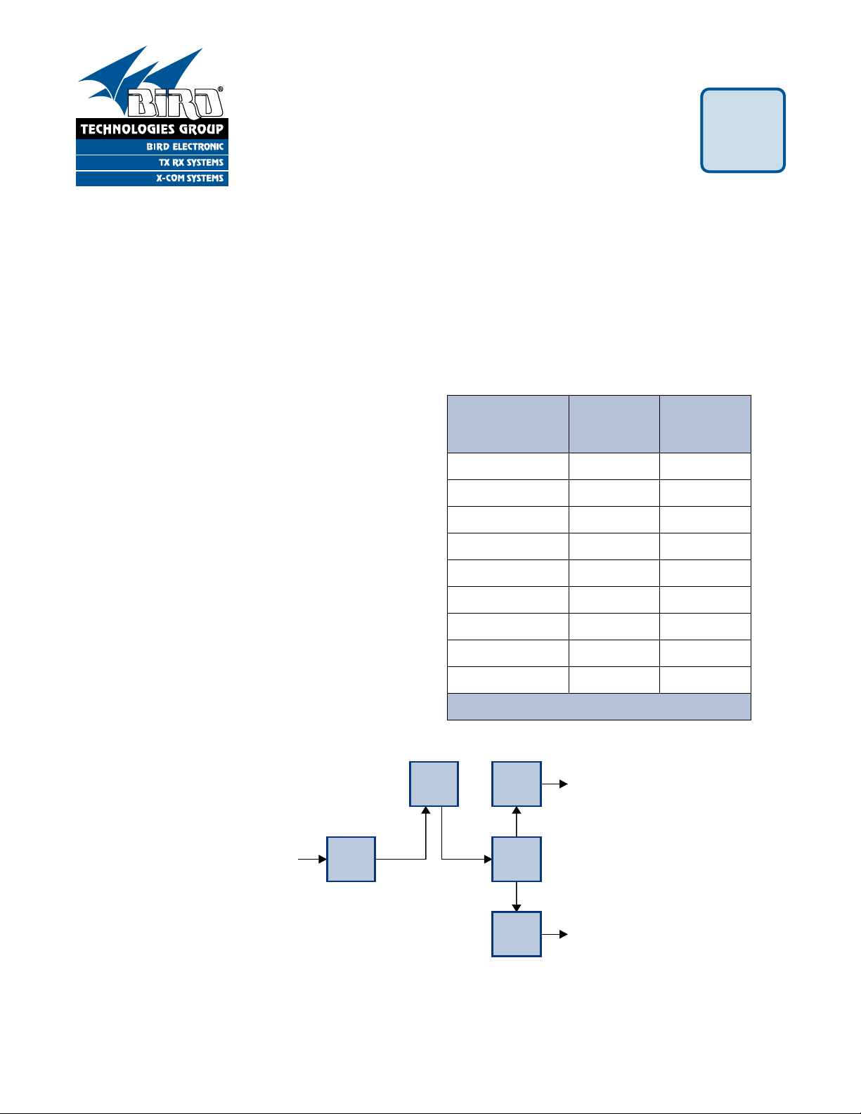
Dist
Amp
Opt
Filter
8-Way
4-Way
8-Way
RF
OUT
RF
OUT
RF IN
From
Tower
Figure 1: Basic interconnect diagram for the optional filter.
Filter
Model
Operating
Range
(MHz)
Bandwidth
(MHz)
89-83F-02-03 792 to 806 3
89-83F-02-06 792 to 806 6
89-83F-02-09 792 to 806 9
89-83F-02-14 792 to 806 14
89-86A-02-03 806 to 824 3
89-86A-02-05 806 to 824 5
89-86A-02-10 806 to 824 10
89-86A-02-15 806 to 824 15
89-86A-02-18 806 to 824 18
Table 1: Optional Narrowband Filters.
7-9434-2
GENERAL DESCRIPTION
This manual details the installation of an optional
narrowband preselector filter for the TX RX Systems Tower Top Amplifier. There are nine different
filters available for use with your TTA system. Four
filters operate in the 792 to 806 MHz range and five
filters in the 806 to 824 MHz range. Table 1 lists all
of the narrowband filters available. The narrowband
filter is designed to be added to the TTA systems
RF signal path just after the distribution amplifier in
the MCU. The additional filter will provide a narrower pass window for the MCU.
Figure 1 shows the basic interconnect diagram for
the filter. It is recommended that the filter be
mounted in the same rack and just above the MCU.
The optional filter will require 2 “rack units” of
space.
INSTALLATION KIT
Included in the installation kit are:
1) Panel-mounted narrowband preselector with
mounting plates.
3) 24-inch SMA / N cable.
4) Required installation screws.
2) 24-inch BNC / N cable.
8625 Industrial Parkway, Angola, NY 14006 Tel: 716-549-4700 Fax: 716-549-4772 sales@birdrf.com www.bird-technologies.com
Page 2
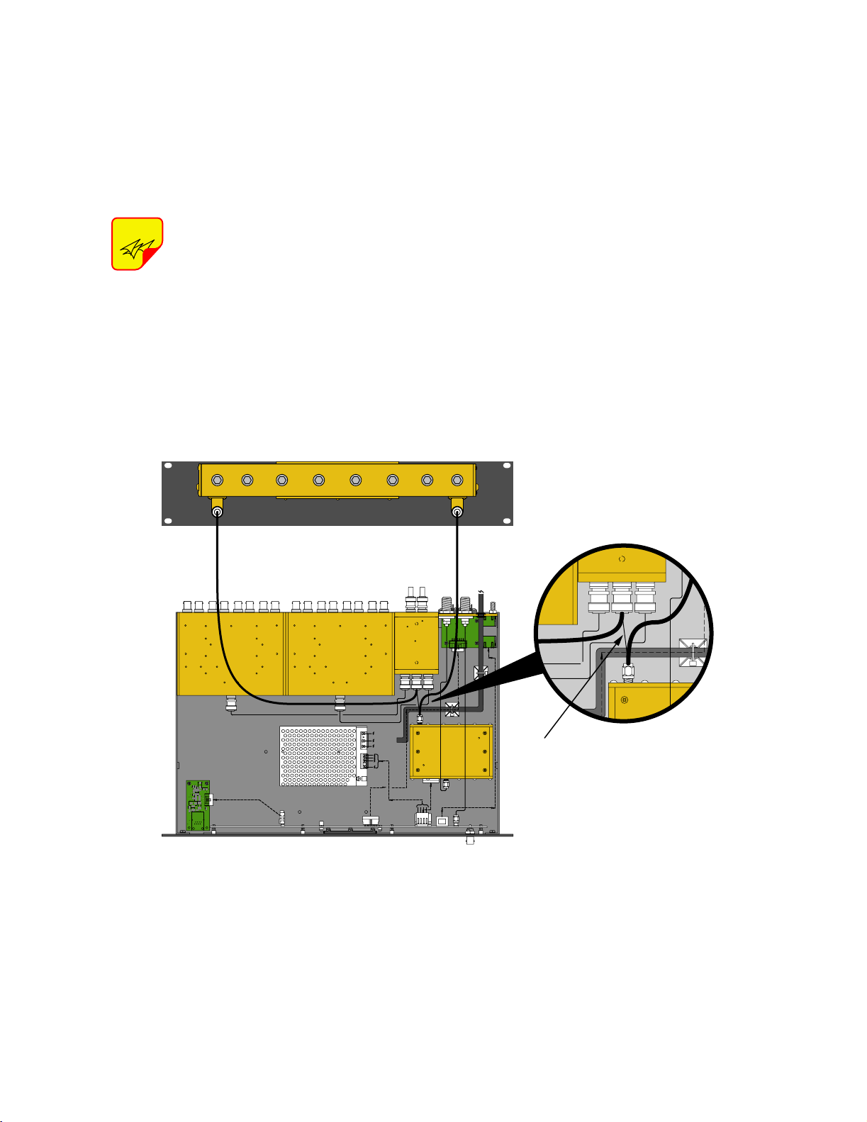
INSTALLATION
Figure 2 shows the cable interconnections that are
required between the filter and the TTA. To install
the optional narrowband filter in your TTA system
perform the following steps;
to save the cable for future re-use if you ever
decide to remove the optional filter from your
TTA system.
2) With the supplied screws, mount the preselector panel into the 19-inch rack above the MCU.
NOTE
off during installation of the preselector.
1) On the MCU, disconnect the existing cable that
runs between the output of the distribution
amplifier and the input of the 4-way divider, see
Figure 2. Use a 5/16” open-end wrench to
loosen the SMA connector on the amplifier end
of the cable. The end of the cable connected to
the 4-way uses a BNC connector. You may wish
Power to the MCU should be turned
3) Locate a new cable assembly with “SMA” and
“N” male connectors. Connect the “SMA” end of
the cable to the output port of the amplifier
assembly. Connect the “N” end of the cable to
the output connector on the preselector.
4) Locate a new cable assembly with “BNC” and
“N” male connectors. Connect the “BNC” end of
the cable to the RF input connector on the 4way divider. Connect the “N” end of the cable to
the output connector on the preselector.
Remove Existing
Cable 3-19152
Figure 2: Connecting the narrowband preselector to the TTA.
TX RX Systems Inc. Manual 7-9434-2 07/15/09 Page 2
 Loading...