

Page 1
!
Bird Gard 270 E. Sun Ranch Drive / P.O. 1690, Sisters, OR 97759 / 541-549-0205 / [email protected] www.BirdGard.com
User’s Manual
Page 2
!1
!
!Table of Contents
Overview 2
Bird Control Management Guidelines 3
Materials List 4
Assembly 5
Placement 6
Building a Mounting Pole 7
Installation 8
Settings 10
Temporary Mute Button 11
Troubleshooting 12
Warranty 13
Bird Gard 270 E. Sun Ranch Drive / P.O. 1690, Sisters, OR 97759 / 541-549-0205 / [email protected] www.BirdGard.com
Page 3
Overview
Bird Gard utilizes the natural survival instincts of birds to effectively repel them." Digital recordings of
distressed and alarmed birds, along with the sounds made by their natural predators are broadcast
through high fidelity weather-resistant speakers." This triggers a primal fear and flee response." Pest birds
soon relocate to where they can feed without feeling threatened.
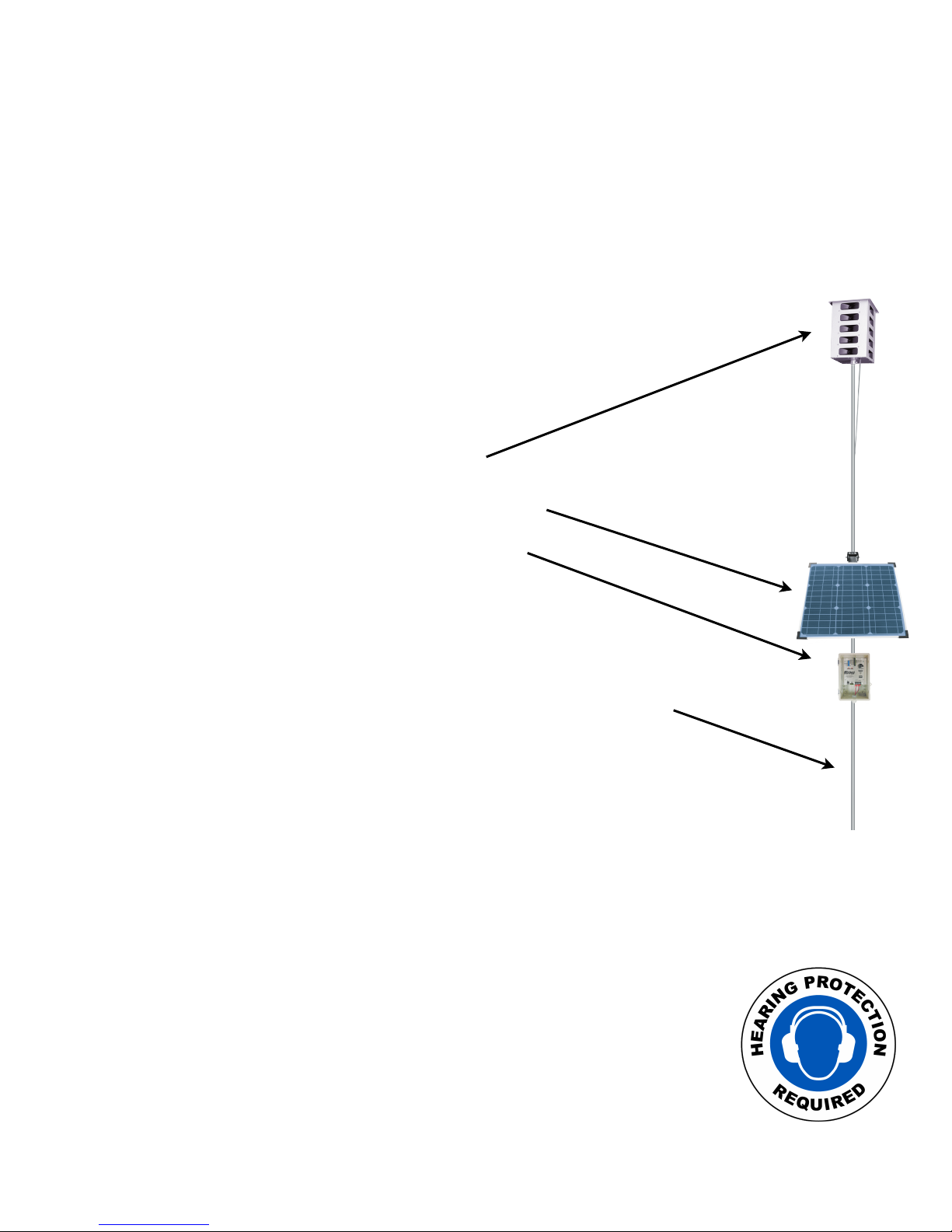
Your Bird Gard Super Pro Amp system consists of:
20-Speaker Tower broadcasts the bird sounds
Solar Panel recharges the 12-volt Deep Cycle Battery
Control Unit produces the bird sounds and contains "
all operational controls
Items needed but not included:
(1) Mounting Pole or Mast tall enough to raise the 20-Speaker Tower "
5 - 10 feet above the top of the crops, trees or other obstructions.
(1) 12-volt Deep Cycle Battery (RV/Marine) Group 27, 100 amp/hr minimum
(1) T-Post (Optional) may be needed to support the mounting pole.
(1) Hose Clamps (Optional) may be needed to secure the"
Mounting Pole to the T-Post
CAUTION: BIRD GARD SUPER PRO AMP PRODUCES SOUNDS UP TO
125 DECIBELS. PROPER HEARING PROTECTION MUST BE WORN
ANYTIME THE UNIT IS IN USE.
Bird Gard Super Pro Amp Users Manual 7/18# !2
Page 4

Bird Control Management Guidelines
An active bird control management program is key to successfully repelling pest
birds. Bird feeding patterns may take several days or weeks to disrupt. Follow all
recommendations for maximum effectiveness. Read all instructions prior to
installation.
For best results:
• It is extremely important to fully protect the entire crop. Any areas not fully protected will allow birds to feed at
the fringes of the sound coverage. They will soon become bolder as they learn the sounds are nothing to fear. This
will cause the effectiveness to diminish. Complete Bird Gard coverage forces birds to abandon the entire protected
area.#
• Install the Bird Gard unit at least two weeks before birds are attracted to your crop as it is much easier to keep birds
away before they have found a food source than it is to repel them once they have developed a feeding pattern. #
• Most birds begin feeding from the perimeter of a crop. Place Bird Gard units so the sound protection covers beyond
the edges of the crop. #
• Birds will often gather in tall trees and use them for roosting and observation. If birds are in bordering trees it is
important to position the units so the sound protection fully covers the trees as well.#
• Mount the 20-Speaker Tower 5 - 10 feet above trees, crops and structures for maximum coverage. Sound will
disperse or reflect off structures or foliage. Mount control unit below the solar panel and out of direct sunlight, if
possible. The solar panel must face south without being shaded by foliage or other obstructions.#
• Your Bird Gard units should be set to FULL volume and on SHORT time-off interval for maximum effectiveness.
Lowering the volume or changing the time off period will greatly reduce the effectiveness. #
• Watch for changes in bird activity and adjust the location of your Bird Gard units if necessary. #
• Check the battery and unit settings periodically to insure continuous bird control. Be certain that the system is not
turned down or OFF, or has a dead battery during crucial times.#
• If bird species appear in the protected area that are not included on the Sound Card, the Sound Card will need to be
updated to repel the new invading birds. #
• Your Bird Gard system is a management tool, and should be used as part of your overall bird control strategy,
sometimes in conjunction with other bird control techniques and devices. #
Be aware that under drought or other extreme conditions, birds will disregard all deterrents and risks in order to
survive
If you have any questions about the use or operation of this product "
call us toll free at 888-332-2328 Monday - Friday 7:30 am-4:00 pm Pacific Time.
Outside the U.S. and Canada call 541-549-0205
Bird Gard Super Pro Amp Users Manual 7/18# !3
Page 5
Materials List
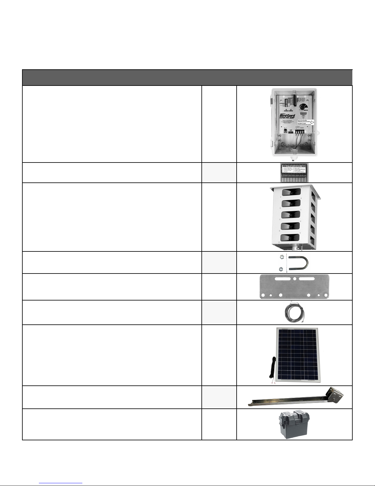
Item
Qty
Bird Gard Super Pro Amp Control Box
1
Bird Gard Sound Card
1
20-Speaker Tower
1
U-Bolts
4
Control Box Brackets
2
Control Box Connector Cable
1
40-Watt Solar Panel
1
Solar Panel Mounting Bracket Assembly "
and Hardware
1
Battery Box
1
Bird Gard Super Pro Amp Users Manual 7/18# !4
Page 6
Assembly
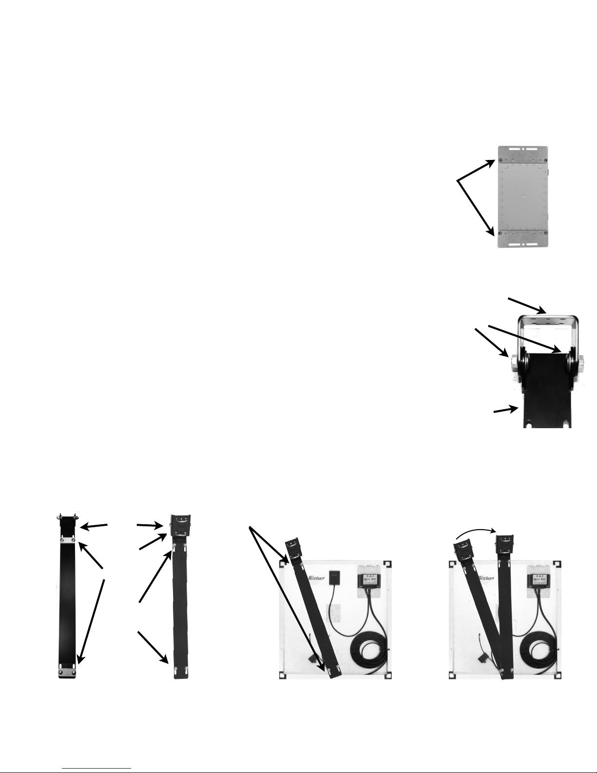
Note: You will find it easier to pre-assemble the following components prior to
installation in the field.
Control Unit
1. Lay the Control Unit face down.
2. Attach the two Control Box Mounting Brackets to the back with the included screws (Figure 1).
3. Discard the 4 small “Z” brackets, they are not needed.
Solar Panel
4. Install two U-Bolts in the Solar Panel Mounting Bracket (Figure 2).
5. Loosen, but do not remove the Carriage Bolts securing the movable Clamp Plates on the Solar "
Panel Mount Bracket.
6. Lay the Solar Panel on a flat surface with the glass side down.
7. Lay the Mounting Arm across the Solar Panel with the Clamp Plates down. Position the Mounting Arm "
at an angle so the Clamp Plates slide under the lip of the Solar Panel (Figure 3A).
8. Rotate the Mounting Arm and secure it to the Solar Panel by tightening the Carriage Bolts (Figure 3B).
Bird Gard Super Pro Amp Users Manual 7/18# !5
Figure 3A
Clamp Plates slide under
the lip of the Solar Panel
Control Box Mounting
Brackets
Figure 1
Bottom View
Top View
Figure 2
Carriage
Bolts
Clamp Plates
Solar Panel Mounting Bracket
Head
U-Bolts
Figure 3B
Solar Panel Mounting Bracket
Mounting Arm
Pivot Bolts
Rotate Mounting Arm and
tighten Carriage Bolts
Page 7

Placement
Your Bird Gard Super Pro Amp will protect an area up to 600 feet in all directions under ideal conditions. #
Factors to consider when selecting the best location include:
• Birds typically feed from the perimeter of the crop and work their way in. Place Bird Gard units so the sound
protection covers beyond the edges of the crop. #
• Mount the 20-Speaker Tower at least 5 - 10 feet above terrain, crops, trees and other obstacles. #
• Placing Bird Gard units on top of a hill or small rise will result in better coverage than at the bottom of a
valley. #
• Wind can blow sounds. If the area you need to protect has consistent wind coming from the same
direction, position your Bird Gard unit more “upwind.”#
• Trees surrounding crops provide birds with a safe place to hide and stage feeding raids Your Bird Gard unit
should be positioned within 300 feet of any trees or heavy foliage bordering your crops. If birds are roosting
in the trees at night the TIME OF OPERATION should be set to 24 HOUR.#
• Lakes, rivers and wetlands are a favorite resting and hiding place for birds. Your Bird Gard unit should be
positioned so the sound extends well into any areas where birds congregate. #
• Neighbors, businesses and others may not appreciate hearing the bird sounds. At the limits of the effective
range the sounds from your Bird Gard unit may be annoying to neighbors. Avoid placing the unit where it
becomes a nuisance. #
• Sound deadening panels are available to limit the sound output in one direction. #
• We will provide free custom mapping showing the suggested location of Bird Gard units on your property if
you will provide your location information or GPS coordinates.#
If you have any questions about the use or operation of this product "
call us toll free at 888-332-2328 Monday - Friday 7:30 am-4:00 pm Pacific Time.
Outside the U.S. and Canada call 541-549-0205
Bird Gard Super Pro Amp Users Manual 7/18# !6
Page 8

Building a Mounting Pole
CAUTION: TALL POLES CAN BE HEAVY AND POTENTIALLY DANGEROUS. USE
EXTREME CAUTION WHEN CONSTRUCTING OR WORKING AROUND TALL POLES
AND MASTS. BIRD GARD, LLC ASSUMES NO RESPONSIBILITY FOR DAMAGES OR
INJURIES.
Things to consider:
•
The 20-Speaker Tower is designed to mount on a pipe with an outside diameter of one inch.$ Both ¾ inch
IMC conduit and ¾ inch galvanized water pipe have an outside diameter of one inch and are available in 10
foot lengths. #
•
You will want to take down your Bird Gard unit after harvest and store it in a dry location until the next
season. #
A suggestion for mounting poles up to 30 feet tall:
1. Use 10 ft. lengths of galvanized 1 in. (O.D.) IMC rigid conduit or water pipe, securely fastened together
with threaded couplers. #
2. Slide the 20-Speaker Tower over the top of the pipe and tighten the set screw in the collar at the base. #
3. Drive two T-Posts into the ground at the base of the pole and secure with two hose clamps. The
assembled mast will sway in the wind but will not adversely effect the performance of your Bird Gard
units. #
Bird Gard Super Pro Amp Users Manual 7/18# !7
Page 9
Installation
Note: Foliage, trees, and other obstructions severely reduce the effective range of Bird
Gard units. It is critical that the 20-Speaker Tower is mounted 5 - 10 feet above all
obstructions to achieve the maximum protection.
Mounting Pole or Mast
1. The Mounting Pole or Mast will need to be supported by a T-Post, fence post, tree or other means. The Pole Support
should be in place before proceeding.
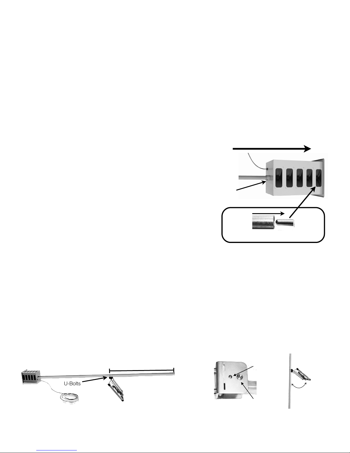
20-Speaker Tower
2. Cut the zip-tie securing the speaker cable to the 20-Speaker Tower.
3. Slide the 20-Speaker Tower over the Mounting Pole (Figure 4A) until it slides
over the positioning pin inside the top of the Tower (Figure 4B).
4. Securely tighten the Set Screws in the Collar at the base of the "
20-Speaker Tower.
"
Solar Panel
5. With the glass side of the solar panel facing the 20-Speaker Tower, slide the U-Bolts in the Solar Panel Mounting Bracket
over the lower end of the Mounting Pole approximately 7 feet from the bottom of the pole and tighten the U-Bolts "
(Figure 5A).
6. Lean up the assembled Mounting Pole against the Pole Support and fasten securely with hose clamps or other semipermanent means.
7. Loosen the Tilt Lock Pin enough to allow the Solar Panel to angle down 45º (Figure 5B), retighten the Tilt Lock Pin and
Pivot Bolts to hold the solar panel angle securely.
8. The Solar Panel MUST be installed facing SOUTH without being shaded by foliage or other obstructions. This may
require mounting it above crops or trees to ensure it receives sufficient sunlight to recharge the battery.
Bird Gard Super Pro Amp Users Manual 7/18# !8
Figure 4A
Collar and Set Screw
Slide Mounting Pole all the way through
the 20-Speaker Tower
U-Bolts
Approximately 7 ft.
Figure 4B
Slide Mounting pole over Positioning Pin
Approx. 45º.
Figure 5B
Tilt Lock Pin
Figure 5A
Page 10
Control Box
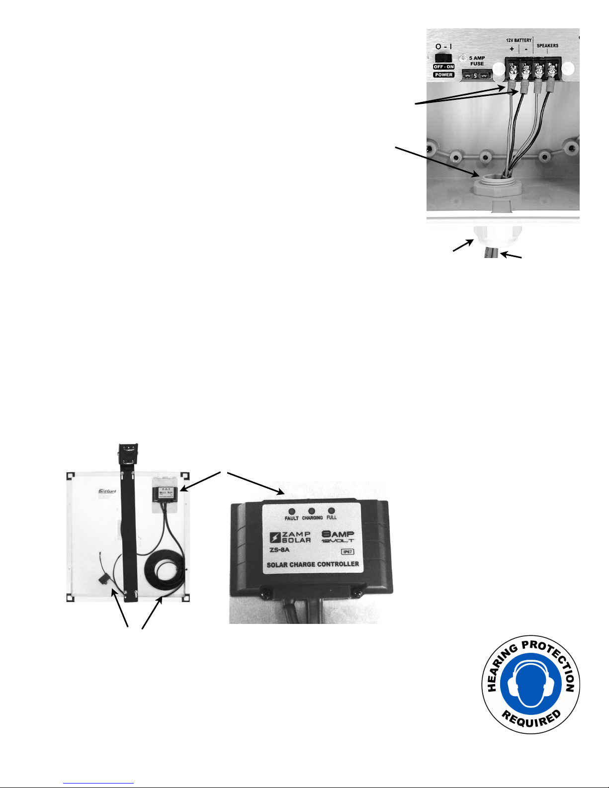
9. Attach the Control Box to the Mounting Pole below the Solar Panel
with U-Bolts.
10. Feed the Speaker Cables through the Cable Strain Relief at the
bottom of the Control Box. (Figure 6)
11. Attach the Speaker Cables from the 20-Speaker Tower to the screws
marked “SPEAKERS” on the faceplate of the control panel.
12. Locate the Control Box Connector Cable (gray 2 wire cable) and feed the
end with the small connectors through the Cable Strain Relief.
13. Connect the RED wire to the screw marked “+” and the BLACK wire to the screw "
marked “-” under “12V BATTERY” on the faceplate of the control panel.
14. MAKE SURE THE POWER SWITCH IS TURNED OFF BEFORE ATTACHING
BATTERY CABLES TO BATTERY.
15. Connect the other end of the RED wire to the “+” terminal on the 12-volt Deep Cycle
battery (not included). Connect the BLACK wire to the “-” terminal on the battery.
16. Hand tighten the Tapered Cinch Nut on the bottom of the Cable Strain Relief to "
help keep insects and moisture out.
Solar Panel Connections
17. Cut the black zip-ties securing the RED and BLACK wires on the underside of the solar panel. (Figure 7)
18. Connect the RED wire to the “+” terminal on the 12-volt battery and connect the BLACK wire to the “-” terminal on the battery.
NOTE: Deep Cycle lead acid batteries (group size 27) are recommended. If using “Sealed Gel” type battery you will need to
change the dip switch settings located on the back of the Solar Controller to prevent overcharging and damaging the battery.
Lift the hinged Solar Controller panel and set switch 1 ON and switch 2 OFF.
CAUTION: BIRD GARD SUPER PRO AMP PRODUCES SOUNDS
UP TO 125 DECIBELS. PROPER HEARING PROTECTION MUST
BE WORN ANYTIME THE UNIT IS IN USE.
Bird Gard Super Pro Amp Users Manual 7/18# !9
Control Box Connector
to Battery
Tapered Cinch
Nut
Figure 6
Speaker and
Battery Cables
Cable Strain
Relief
Figure 7
RED and BLACK wires
connect to BATTERY
Solar Controller
Charging Status Lights
•
Fault (Red): The solar panel is not
connected correctly
•
Charging (Blue): Charging properly
•
Full (Green): The battery is fully charged
Page 11
Settings
Repelling birds requires regular monitoring and active management. Birds are intelligent and
highly adaptable so it is important to create and maintain an environment the birds perceive
as hostile and dangerous. This is achieved by playing the sounds frequently and at a high
volume, otherwise the birds will not be fully repelled and will soon learn to adapt. #
Below are the initial settings that should be used when your Bird Gard Super Pro Amp is first
installed. Please see the “Bird Control Management Guidelines” section for more
information.#
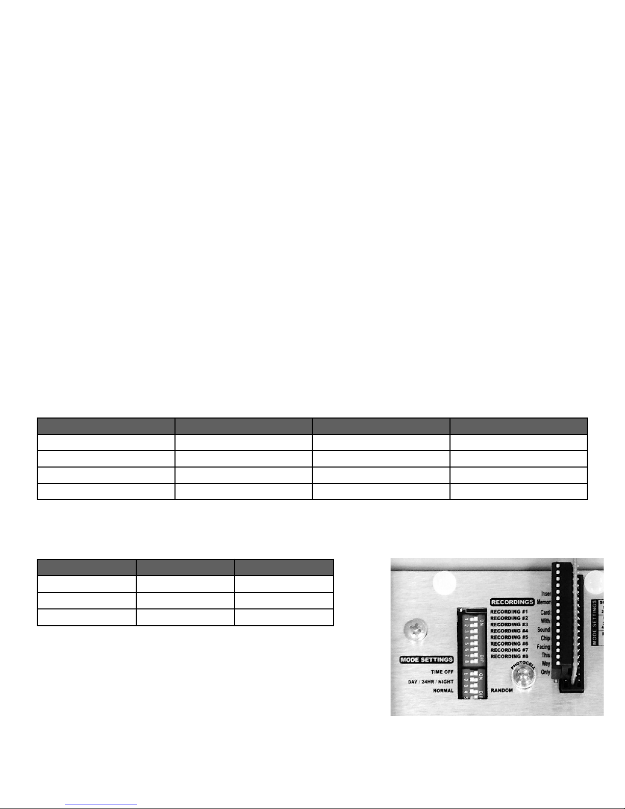
Recordings
There are eight separate bird sounds contained on the Replaceable Sound Card. The label on the Sound Card lists each bird sound with a
corresponding number to the eight “RECORDINGS” dip switches to the left of the Sound Card. Initially all RECORDING switches should be
turned ON. If the target birds begin returning, periodically change switch settings for the eight sounds (turning them ON or OFF). "
NOTE: NEVER turn OFF the distress or alarm calls of the target birds you are trying to repel and always keep at least one
predator bird sound turned ON.
Mode Settings
TIME OFF INTERVAL controls the time off periods between each playing of the bird recordings.
TIME OFF INTERVAL should be set to SHORT to create the greatest sense of danger and move the birds out of the area the
fastest. NOTE: Increasing the TIME OFF INTERVAL may lower the effectiveness of your Bird Gard unit.
TIME OF OPERATION controls when the bird recordings play.
Birds are usually only active during the day so the DAY ONLY is recommended. "
If birds are in the area at night set TIME OF OPERATION for 24-HOUR.
RANDOM OPERATION should always be turned ON.
Volume
Should always be set to HIGH for maximum coverage.
Setting
Time Off Duration
Switch #1
Switch #2
SHORT
17-50 Seconds
ON
OFF
MEDIUM
1:00-4:15 Minutes
OFFONLONG
5:00-10:00 Minutes
ON
ON
XLONG
10:00-30:00 Minutes
OFF
OFF
Setting
Switch #3
Switch #4
DAY ONLY
ON
OFF
24-HOUR
OFF
ON
NIGHT ONLY
ON
ON
Bird Gard Super Pro Amp Users Manual 7/18# !10
Recommended Settings
Page 12
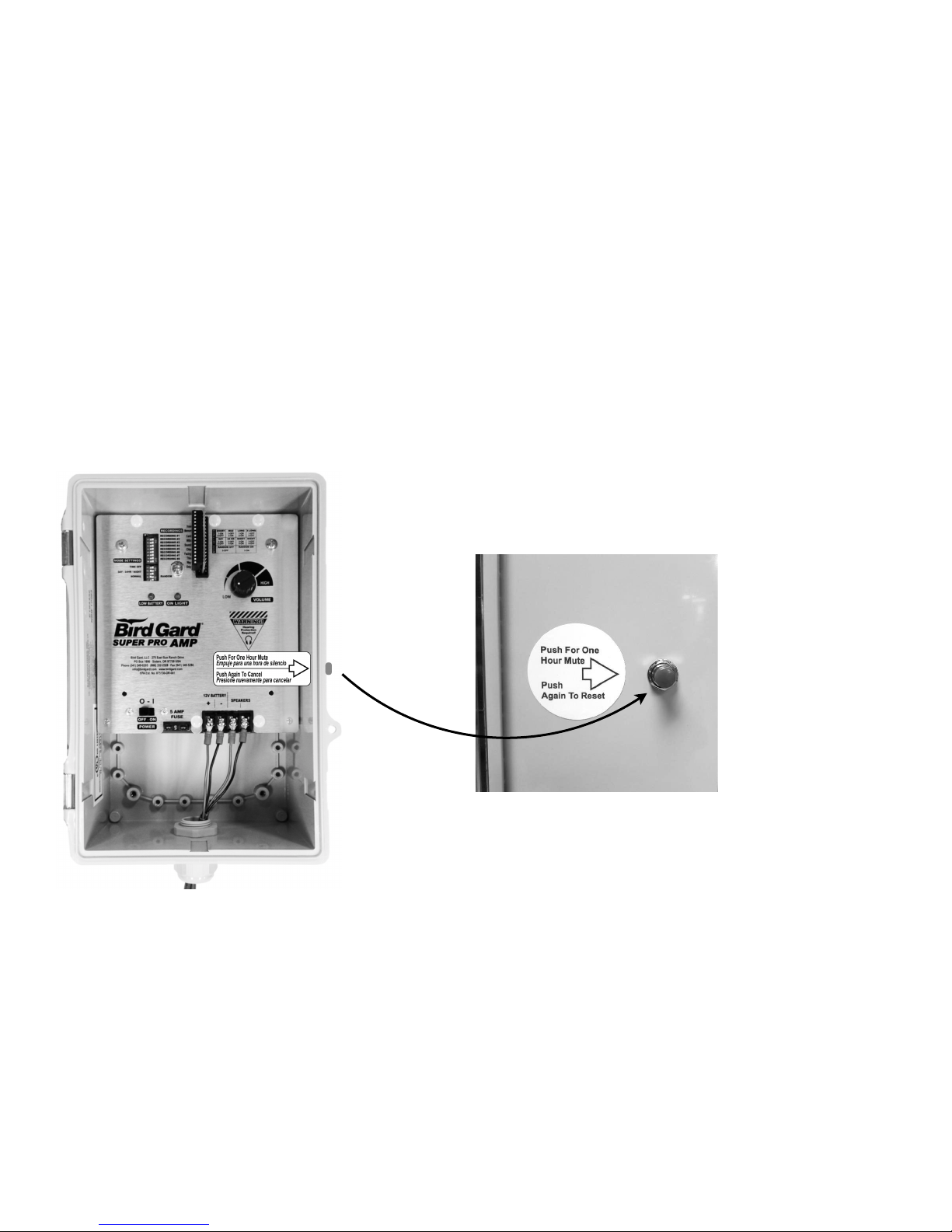
Temporary Mute Button
Your Bird Gard Super Pro Amp unit is equipped with an external Temporary Mute Button
located on the right side of the control box. Pressing the Mute Button silences the unit for
approximately 1-hour, then it automatically resumes normal operation at full volume. This
allows people to work in the vicinity without being disturbed by the bird sounds. #
To Activate Mute
Press the RED BUTTON on the right side of the control box ONCE."
To De-Activate Mute
Press the RED BUTTON on the right side of the control box again, or wait 1-hour.
"
"
"
Bird Gard Super Pro Amp Users Manual 7/18# !11
Page 13
"
Troubleshooting
If you have any questions about the use or operation of this product "
call us toll free at 888-332-2328 Monday - Friday 7:30 am-4:00 pm Pacific Time.
Outside the U.S. and Canada call 541-549-0205
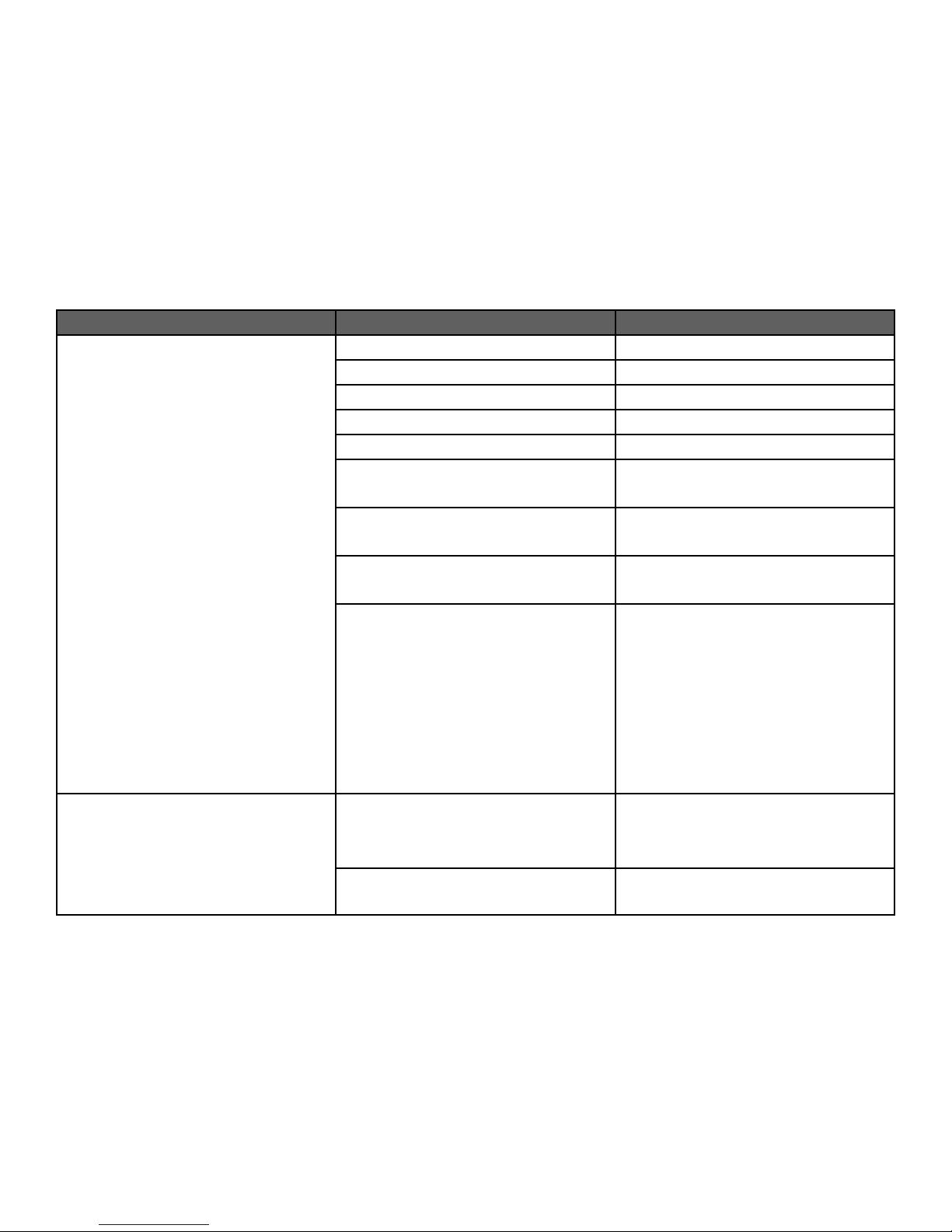
Problem
Possible Cause
Solution
No Sound
Temporary Mute Button Activated
Press button once
Volume turned down
Turn volume up
Dead battery
Charge or replace battery
Loose battery connection
Verify all battery connections are tight
All RECORDINGS are turned OFF
Verify all RECORDINGS are switched to ON
Sound Card not fully seated
Remove sound card and reinstall, making
sure it is fully inserted into the socket
Sound Card is installed backward
Unplug the sound card and reinstall with the
label facing to the right
TIME OF OPERATION set to DAY ONLY
without enough light
Change TIME OF OPERATION to 24-HOUR
Unit was not shut down before the battery
was disconnected causing the unit to go into
“SAFE MODE”
1. Turn the POWER switch OFF
2. Disconnect the battery
3. Remove the sound card
4. Wait 30 seconds
5. Reinstall sound card
6. Reconnect the battery
7. Turn the POWER switch ON
Was working but stopped
The battery is dead
Connect the battery to a battery charger and
see if it will hold a charge.
Replace if necessary
Solar Panel is not getting enough sunlight
Reposition the Solar Panel and recharge the
battery
Bird Gard Super Pro Amp Users Manual 7/18# !12
Page 14
Warranty
1-YEAR ABSOLUTE SATISFACTION GUARANTEE:!
IF YOU ARE NOT COMPLETELY SATISFIED WITH THE PURCHASE OF ANY BIRD GARD® PRODUCT, CONTACT
THE PLACE OF PURCHASE OR OUR CUSTOMER SERVICE DEPARTMENT WITHIN 1 YEAR OF YOUR DATE OF
PURCHASE FOR PROMPT AND COURTEOUS REPLACEMENT, REPAIR OR REFUND.
BIRD GARD LLC'S LIABILITY HEREUNDER SHALL BE LIMITED TO REFUNDING THE PURCHASE PRICE PAID
BY CUSTOMER OR REPLACING THE PRODUCT, IN BIRD GARD'S SOLE DISCRETION, AND UNDER NO
CIRCUMSTANCES SHALL BIRD GARD BE LIABLE FOR ANY CONSEQUENTIAL OR INCIDENTAL DAMAGES, OF
ANY NATURE WHATSOEVER, ARISING FROM THE CUSTOMER'S USE OR OPERATION OF THE PRODUCT;
PROVIDED, HOWEVER, THAT THIS LIMITATION MAY BE LIMITED BY STATE LAW."
"
EXCEPT FOR THE EXPRESS ONE-YEAR LIMITED WARRANTY BIRD GARD DISCLAIMS ALL OTHER
WARRANTIES, EXPRESS OR IMPLIED, RELATING TO THE PRODUCT, INCLUDING, BUT NOT LIMITED TO, ANY
IMPLIED WARRANTY OF MERCHANTABILITY OR IMPLIED WARRANTY OF FITNESS; AND THE EXPRESS
WARRANTIES ARE IN LIEU OF ALL OBLIGATIONS OR LIABILITIES ON THE PART OF BIRD GARD ARISING OUT
OF OR IN CONNECTION WITH THE SALE, USE, OR OPERATION OF THE PRODUCT."
If you have any questions about the use or operation of this product "
call us toll free at 888-332-2328 Monday - Friday 7:30 am-4:00 pm Pacific Time.
Outside the U.S. and Canada call 541-549-0205
270 E. Sun Ranch Drive& & & & & & & & & '
P.O. Box 1690'
Sisters, OR 97759'
Toll Free 888-332-2328'
Outside the U.S. and Canada 541-549-0205'
www.BirdGard.com [email protected]#
Bird Gard Super Pro Amp Users Manual 7/18# !13
Item #655-0040-00
 Loading...