

Page 1
A Member of Bird Technologies Group
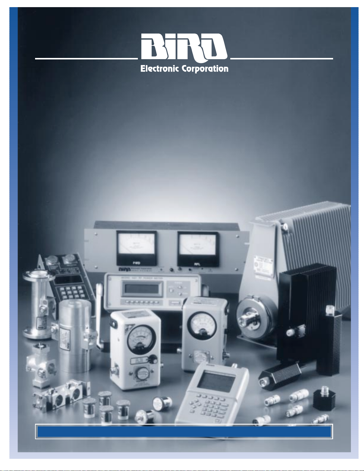
GENERAL CATALOG
AND
APPLICATIONS GUIDE
QUALITY INSTRUMENTS FOR RF POWER MEASUREMENTS
Page 2
OUR MISSION...
Bird Technologies Group is committed to meeting its customers’ needs for innovative RF and
communication products around the globe. With representation in over 45 countries, you can
count on us for quality solutions, excellent service, and long-term reliability.
BIRD TECHNOLOGIES GROUP
Bird Technologies Group (BTG) is the parent of Bird Electronic
Corporation, Bird Component Products, and TX RX Systems Inc.
BTG brings the synergy of several companies with proven
leadership and expertise in the fields of RF measurement,
manufacturing, and communication technology.
■
RF Power Meters
■
High-Power Line Sections and Components
■
Antenna Testers
■
High-Power Loads and Attenuators
■
VSWR Alarms and Power Monitors
For use in:
■
PCS, Cellular and other Wireless Services
■
Conventional and Digital Broadcast
■
Semiconductor Fabrication
■
Traditional and Two-way Paging
■
Mobile and Two-way Radio
■
T-Pass®Transmit-Receive Multicouplers
■
Signal Booster Systems
■
Tower Mount Preamps
■
Broadband Base Station Antennas
■
Resonant Cavity Filters
■
RF System Components
For use in:
■
Wireless Infrastructure OEM
■
System Integrators
■
Wireless Carriers
■
PCS
■
Specialized Mobile Radio
■
Two-way Radio
■
Paging
■
Coaxial RF Terminations
■
Coaxial RF Attenuators
■
Hybrid Coaxial Dividers/Combiners
For use in:
■
Wireless Infrastructure OEM
■
Wireless System Design
■
General Purpose RF Test and Measurement
30303 Aurora Road
Cleveland, Ohio 44139
Phone: 440-248-1200
Fax: 440-248-5426
30303 Aurora Road
Cleveland, Ohio 44139
Phone: 440-248-1200
Fax: 440-248-5426
8625 Industrial Parkway
Angola, New York 14006
Phone: 716-549-4700
Fax: 716-549-4772
Page 3
3
PRODUCT PAGE
ANTENNA TESTERS . . . . . . . . . . . . . . . . . . . . . . . . . . . . . . . . . . . . . . . . . . . . . . . . . 4–5
LABORATORY GRADE INSTRUMENTS . . . . . . . . . . . . . . . . . . . . . . . . . . . . . . . . . . . 6–8
WATTMETERS, AND PRODUCTS FOR 50-OHM CABLE SYSTEMS AND 7⁄8" LINE . 9–28
PRODUCT SELECTION GUIDE. . . . . . . . . . . . . . . . . . . . . . . . . . . . . . . . . . . . . . . . 9
PORTABLE WATTMETERS . . . . . . . . . . . . . . . . . . . . . . . . . . . . . . . . . . . . 10–16, 21
DIGITAL RF SIGNAL WATTMETER. . . . . . . . . . . . . . . . . . . . . . . . . . . . . . . . . . . . 11
TEST SETS. . . . . . . . . . . . . . . . . . . . . . . . . . . . . . . . . . . . . . . . . . . . . . . . . . . . . . . 14
PANEL-MOUNT WATTMETERS . . . . . . . . . . . . . . . . . . . . . . . . . . . . . . . . . . . 17–18
WATTCHER
®
RF MONITORING SYSTEM . . . . . . . . . . . . . . . . . . . . . . . . . . . . 19–20
SIGNAL SAMPLERS . . . . . . . . . . . . . . . . . . . . . . . . . . . . . . . . . . . . . . . . . . . . . . . 22
FIELD-STRENGTH METER AND ELEMENT. . . . . . . . . . . . . . . . . . . . . . . . . . . . . . 22
METER MOVEMENTS AND
7
⁄8" LINE SECTIONS . . . . . . . . . . . . . . . . . . . . . . . . . 23
CASES. . . . . . . . . . . . . . . . . . . . . . . . . . . . . . . . . . . . . . . . . . . . . . . . . . . . . . . . . . 24
PLUG-IN ELEMENTS. . . . . . . . . . . . . . . . . . . . . . . . . . . . . . . . . . . . . . . . . . . . 25–28
WATTMETERS AND PRODUCTS FOR 15⁄8" – 61⁄8" RIGID LINE SYSTEMS . . . . . . 29–38
PRODUCT SELECTION GUIDE. . . . . . . . . . . . . . . . . . . . . . . . . . . . . . . . . . . . . . . 29
WATTMETER PACKAGES. . . . . . . . . . . . . . . . . . . . . . . . . . . . . . . . . . . . . . . . 30–31
WATTCHER
®
RF MONITORING SYSTEM . . . . . . . . . . . . . . . . . . . . . . . . . . . . 32–33
RIGID LINE SECTIONS . . . . . . . . . . . . . . . . . . . . . . . . . . . . . . . . . . . . . . . . . . . . . 34
METERS FOR RIGID LINE USE . . . . . . . . . . . . . . . . . . . . . . . . . . . . . . . . . . . . . . . 35
PLUG-IN ELEMENTS. . . . . . . . . . . . . . . . . . . . . . . . . . . . . . . . . . . . . . . . . . . . 36–38
ABSORPTION WATTMETERS . . . . . . . . . . . . . . . . . . . . . . . . . . . . . . . . . . . . . . . . 39–41
RF COAXIAL TERMINATIONS . . . . . . . . . . . . . . . . . . . . . . . . . . . . . . . . . . . . . . . . 42–53
RF COAXIAL ATTENUATORS. . . . . . . . . . . . . . . . . . . . . . . . . . . . . . . . . . . . . . . . . 54–58
ACCESSORIES AND CONNECTORS. . . . . . . . . . . . . . . . . . . . . . . . . . . . . . . . . . . . 59–61
TECHNICAL INFORMATION . . . . . . . . . . . . . . . . . . . . . . . . . . . . . . . . . . . . . . . . . 62–64
INDEX . . . . . . . . . . . . . . . . . . . . . . . . . . . . . . . . . . . . . . . . . . . . . . . . . . . . . . . . . . 65–66
TABLE OF CONTENTS
Look for these symbols which identify whether
an instrument is used with 50-ohm Cable and
7
⁄8"Rigid Line, or High-Power Rigid Line
RF Systems.
FOR YOUR CONVENIENCE
Bird Electronic Corporation maintains an aggressive program of testing products for conformity to applicable
electromagnetic and safety standards, including European EEC directives. We are proud to announce that,
where applicable, Bird products carry the “CE” mark. A CE-marked product complies with relevant EEC directives
and is approved for sale to the European Union.
The continuing phase-in of new EEC directives may periodically affect the status of some products. However, any Bird product offered for sale to the European Union will conform to all EEC directives in effect at the time of shipment. Please consult
your local Bird sales office or Bird Electronic Corporation regarding questions about CE compliance of any Bird product.
Rigid LineRigid Line
PrProductsoducts
Page 4
Phone: 440-248-1200 • Fax: 440-248-5426
4
ANTENNA TESTERS
HF, VHF, and UHF
Bird’s AT-Series Antenna Testers bring a new dimension to the testing of HF, VHF,
and UHF antenna systems. Powerful, yet remarkably easy to use, these instruments
can test an entire band in a matter of seconds. And unlike conventional antenna
testers, Bird’s advanced design provides accurate results regardless of antenna
cable length. Menu driven, software-defined keys and digital keypad permit quick
selection of operating mode and direct entry of test parameters. A self-contained
RF source lets you precisely set the test frequency – no external transmitter is
needed. A built-in adaptable antenna jack mates a wide range of standard
RF connectors. Plus, compact size and rechargeable batteries provide for truly
portable operation.
■
Swept Frequency Measurements – Fast scans show VSWR, Match Efficiency
or Return Loss across the entire band. A moveable cursor can be used
to pinpoint scan frequency and digitally display the corresponding
measurement value.
■
Single-Frequency Mode – Can be used to optimize antenna performance
and troubleshoot intermittent problems.
■
Limit Testing – Quick Pass-Fail indicator compares measurements to user
selected limits.
■
Audible Indicator – Pitch varies with match condition. You can keep your
eyes and hands on adjustments and simply listen for the best match.
■
Field-Strength Measurements – Verifies the output of devices such as portable
radios and cellular phones.
■
Data Storage – Saves and recalls up to 12 scans in nonvolatile memory
for long-term monitoring of antenna performance or degradation.
■
Serial Communication Link – Optional software uploads data to a
personal computer for analysis or storage.
■
Back-lit Liquid Crystal Display – More rugged than mechanical movements,
more versatile than digital displays, and visible in any light. The LCD also
produces high-resolution graphics.
■
Portable – Lightweight, easy-to-carry, with rechargeable batteries.
■
Rugged – Designed to meet the harsh environment requirements
of MIL-T-28800.
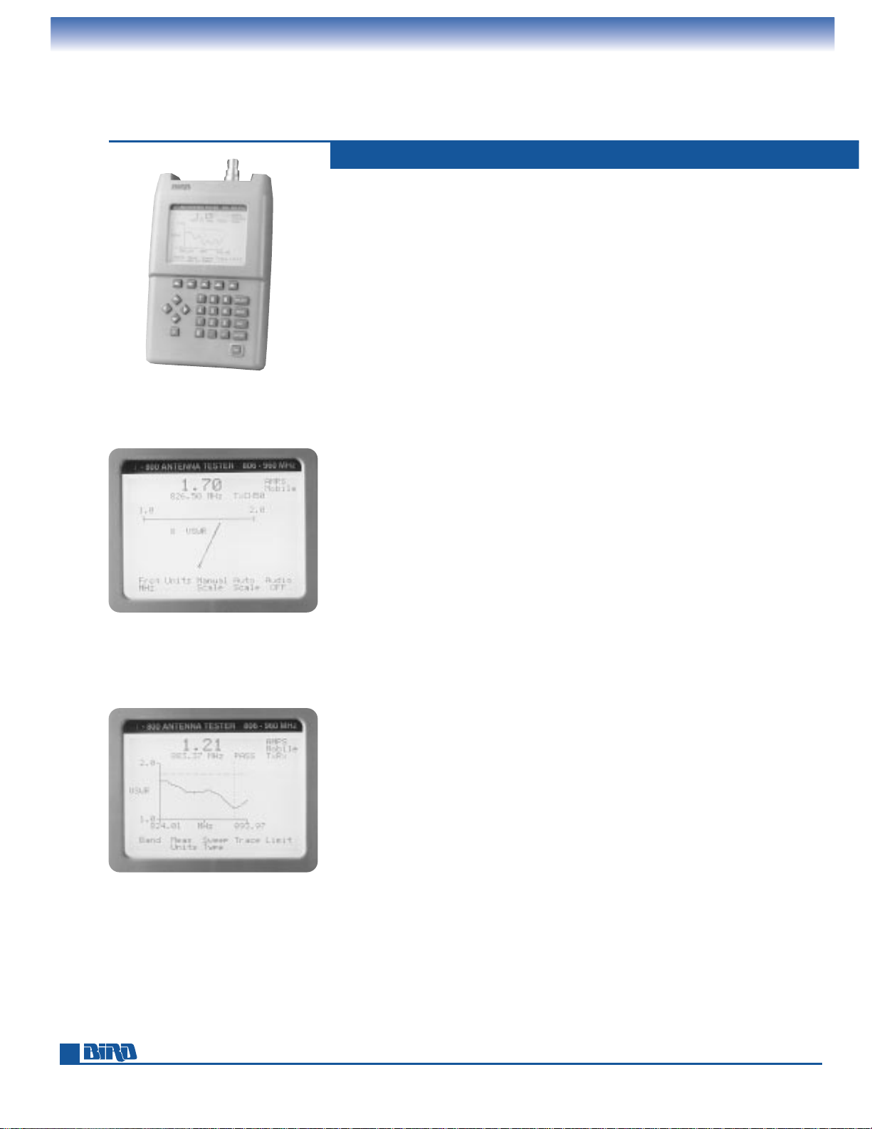
MEASURE VSWR, MATCH EFFICIENCY, RETURN LOSS, FIELD STRENGTH
MODEL AT-800
Single frequency mode
for antenna tuning.
Swept frequency mode reveals
a comprehensive picture of
antenna matching.
Page 5

5
MODELS AT-100, AT-400, AT-800
ANTENNA TESTERS
HF, VHF, and UHF
MODEL: AT-100 AT-400 AT-800
Frequency Range: 2 –136 MHz 80 –520 MHz 806 –960 MHz
Frequency Resolution: 20 kHz 30 kHz 30 kHz
Frequency Accuracy:
±
50 kHz
±
100 kHz
±
100 kHz
Measurement Range:
VSWR: 1.00 – 99.99 1.00 – 99.99 1.00 – 99.99
Match Efficiency: 0.0 to 100.0% 0.0 to 100.0% 0.0 to 100.0%
Return Loss: 0.0 to –32.0 dB 0.0 to –32.0 dB 0.0 to –32.0 dB
Measurement Speed (Typical):
Single Frequency: 5 readings/second 5 readings/second 5 readings/second
Swept Frequency: 1 sweep/second 1 sweep/second 1 sweep/second
Preprogrammed Bands: None None AMPS, NADC, GSM, PDC, CT2
Field Strength:
Range: 0 to 100% (relative) 0 to 100% (relative) 0 to 100% (relative)
Sensitivity: Full-scale deflection Full-scale deflection Full-scale deflection
at 8 v/m @ 100 MHz at 0.22 v/m @ 400 MHz at 3m @ 12.6 W ERP
Test Port:
Impedance: 50-ohm nominal 50-ohm nominal 50-ohm nominal
Connector N (F) included N (F) included TNC (F) included
(Field-changeable): Others available Others available Others available
Interface: Serial Serial Serial
(female DB-9 connector) (female DB-9 connector) (female DB-9 connector)
Power Requirements:
Batteries: Six rechargeable AA Six rechargeable AA Six rechargeable AA
(KR-15/51) (KR-15/51) (KR-15/51)
External DC: 11 to 16 Vdc 11 to 16 Vdc 11 to 16 Vdc
External AC Adapter: 108 to 132 Vac 108 to 132 Vac 108 to 132 Vac
@ 57 to 63 Hz @ 57 to 63 Hz @ 57 to 63 Hz
or 207 to 253 Vac or 207 to 253 Vac or 207 to 253 Vac
@ 48 to 52 Hz @ 48 to 52 Hz @ 48 to 52 Hz
Operating Temperature: 0° to 50°C 0° to 50°C 0° to 50°C
(32° to 122°F) (32° to 122°F) (32° to 122°F)
Storage Temperature: –41° to 71°C –41° to 71°C –41° to 71°C
(–40° to 160°F) (–40° to 160°F) (–40° to 160°F)
Size (including connector): 8" H x 45⁄8" W 8" H x 45⁄8" W 8" H x 45⁄8" W
× 13⁄4" D × 13⁄4" D × 13⁄4" D
(204 mm
× 118 mm (204 mm ×118 mm (204 mm × 118 mm
× 42 mm) × 42 mm) × 42 mm)
Weight: 13⁄4 lbs. (0.8 kg) 13⁄4 lbs. (0.8 kg) 13⁄4 lbs. (0.8 kg)
Supplied Accessory: Field-strength antenna Field-strength antenna Field-strength antenna
Recommended Accessories:Carry case Carry case Carry case
(Model 7000A850), (7000A850), (7000A850),
Windows
®
Interface Windows®Interface Windows®Interface
Software (Model 7000A840), Software (7000A840), Software (7000A840),
Cigarette Lighter Adapter Cigarette Lighter Adapter Cigarette Lighter Adapter
(Model 5A2238-1) (Model 5A2238-1) (Model 5A2238-1)
Verfication Kit 7000A145 Verification Kit 7000A145 Verification Kit 7000A845
AT series antenna testers
are compact, truly portable
and solidly built for goanywhere service.
Windows®is a registered trademark of Microsoft Corporation.
Page 6
Phone: 440-248-1200 • Fax: 440-248-5426
6
LABORATORY
GRADE INSTRUMENTS
THRULINE®High-Accuracy RF Power Meter
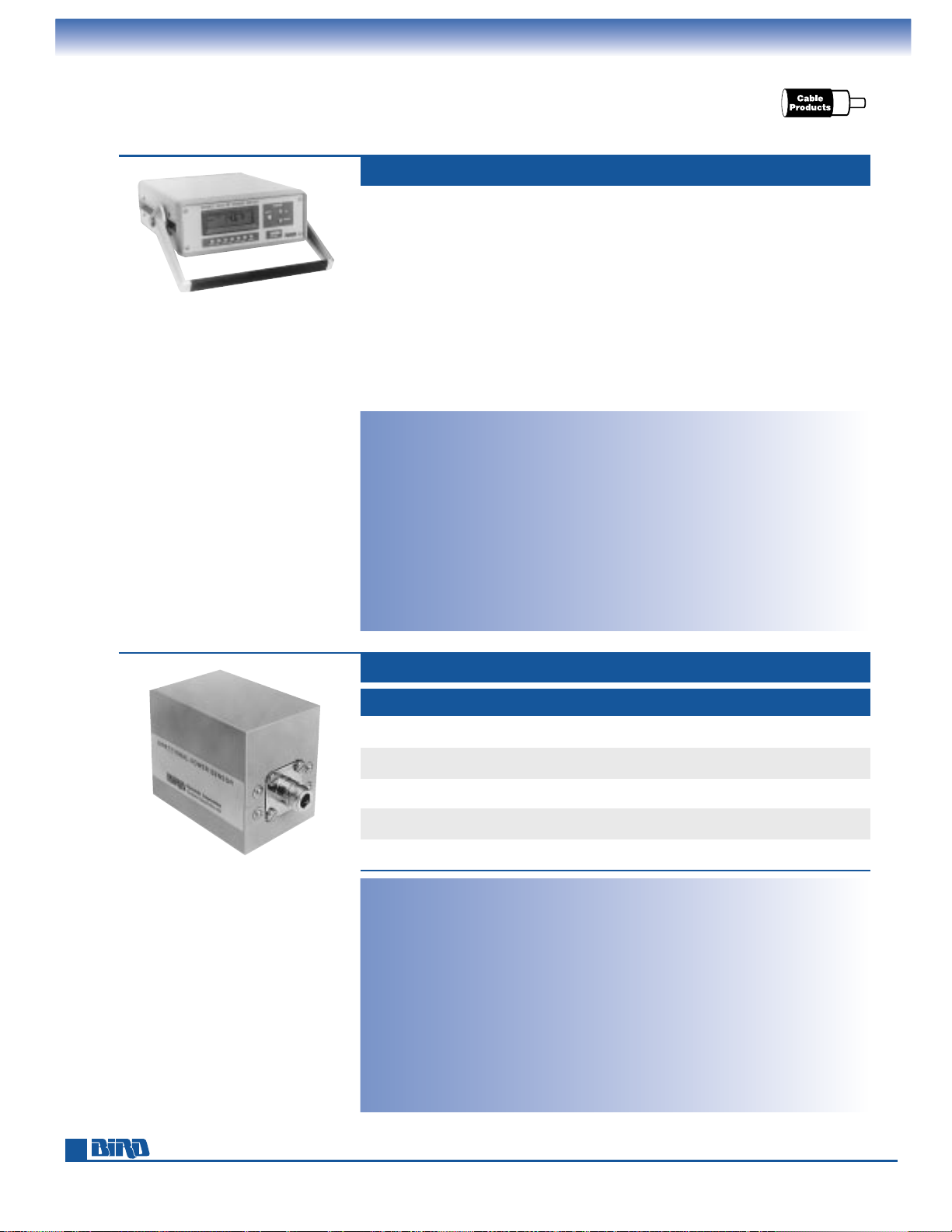
Our Model 4421 power meter is an excellent choice for demanding calibration,
process control and scientific applications. It directly measures power with an
accuracy of ±3% of reading without calibration charts, couplers, attenuators, or
other external equipment which can degrade accuracy.
The backlit 3
1
⁄2-digit LCD displays forward and reflected power in either watts
or dBm, VSWR, return loss in dBm and Minimum or Maximum values. Ranging is
selectable manual or autoranging. An optional GPIB or RS-232 computer interface
can be used with the Model 4421 during AC operation.
Smart Power Sensors (see below) are required for operation. Each covers an extended
frequency and power range. The microprocessor based sensors contain nonvolatile
memory to store calibration data, and can easily be recalibrated in the field.
Power Range: 100 mW to 10 kW FS
Frequency Range: 100 kHz to 2.5 GHz
VSWR Range: 1.0 – 199.9
Functions: Forward and reflected power in
W or dBm, VSWR, return loss in dB and
min/max values
Ranging: Selectable manual or autoranging.
Power sensor dependent.
Overrange Indication: Audible warning when
RF power input exceeds 120% of
sensor’s maximum power range.
Display: 31⁄2digit-liquid crystal display with
annunciator for mode, measurement units,
battery condition, programming status,
and trend arrows. Switchable backlight.
MULTIFUNCTION POWER METER MODEL 4421
Operating Power: AC mains or batteries.
115/230 Vac, 50/60 Hz or 8 nickel cadmium
1.2 V C cells (NEDA type 10014).
Nominal Size: 129⁄32" L ×125⁄32" W ×41⁄4" H
(312 mm x 309 mm
×
108 mm) with handle
extended 15
7
⁄16"L (392 mm)
Weight: 11 lbs. (5 kg.)
Interconnects: 1 meter latch-n-lok coiled cable.
Interfaces: Optional field-installable
IEEE-488 (PN: 4421-488) or RS-232 serial
interface (PN: 4421-232).
Dimensions: 4
1
⁄2" ×61⁄2" (114 ×165 mm)
Required Product: Order a Smart RF Power
Sensor below
Recommended Accessories: Case (page 7)
Circuitry: Microprocessor-based measurement
and conversion.
Frequency/Power Coverage: Single power
sensor covers specified power and
frequency range.
Bi-directional Operation: Pick up of RF power
in precision 50-ohm line.
Accuracy:
±
3% of reading from rated
maximum range down to 30% of
full scale on the most sensitive range.
Signal Purity: For rated accuracy, no more than
1% AM; harmonics –50 dB or less.
Calibration Technique: Calibration vs frequency
curve stored in nonvolatile memory within
each sensor. Sensor output corrected at frequency of measurement within rated stage.
SMART POWER SENSORS 4020 SERIES
Sampling Rate: Approximately 2 readings/second.
Ambient Temperature Range: Temperature
compensated for rated accuracy from
0˚C to 50˚C (32˚F to 122˚F).
Connectors: QC-type. Female N normally
supplied; Other coaxial-type connectors
available on page 60.
Nominal Size: (includes connectors)
5
7
⁄32" L ×21⁄2" W ×31⁄4" H
(132.5 mm
×
64 mm ×83 mm).
Weight: 1 lb. 11 oz. (0.76 kg).
MODEL
POWER FREQUENCY VSWR MINIMUM INSERTION
INPUT RANGE RANGE DIRECTIVITY LOSS (DB)
4021 300 mW – 1000 W 1.8 MHz – 32 MHz 1.0 – 2.0 28 <0.05
(1200 W max.)
4022 300 mW – 1000 W 25 MHz – 1000 MHz 1.0 – 2.0 28 25 – 512 MHz: <0.05
(1200 W max.) 512 – 1000 MHz: <0.13
4023 100mW – 200W 900 MHz – 2500 MHz 1.0 – 3.0 20 <0.2
(240 W max.)
4024 3 W – 10 kW 1.5 MHz – 32 MHz 1.0 – 2.0 28 <0.05
(12 kW max.)
4025 3 W – 10 kW 100 kHz – 2500 kHz 1.0 – 2.0 28 <0.05
(12 kW max.)
Page 7
E-mail: [email protected] • Internet: www.bird-electronic.com
7
LABORATORY
GRADE INSTRUMENTS
THRULINE®High-Accuracy Power Meter, Model 4421 Accessories
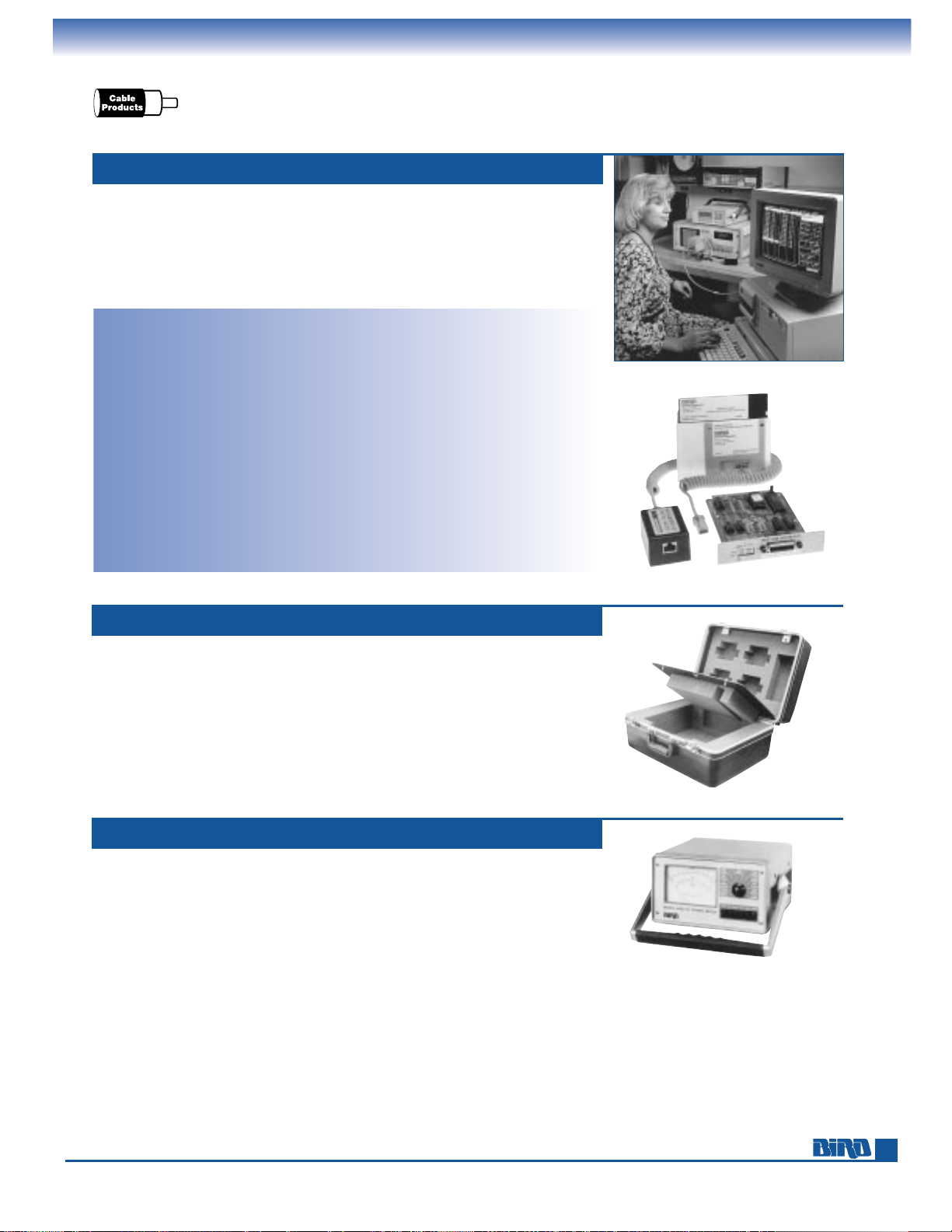
The 4421A500 calibration kit lets you calibrate and maintain calibration histories
of 4020 Series power sensors used with your 4421 power meter. The kit consists of a
calibration card (must be installed in your 4421 power meter), calibration key, sensor
cable, software for your PC and instruction book. Use the kit with an RF power
source, RF low-pass filter, RF terminating power standard like the Bird Model 6091
calorimeter and IBM compatible computer fitted with a GPIB card.
Calibration Software: 31⁄2" and 51⁄4"
diskettes supplied
Plug-in Card Module:
Logic Level:
Meets all IEEE standard
488-1978 specs
Operating Modes: (Switch & Bus Selectable)
Talk Only: Keyboard can command meter
to output a measurement to the bus
Addressable: IEEE-488 bus controller
command can give power meter a talker
of listener address
Connector: Standard IEEE-488 bus type
Temperature Range:
Operational: 0° to 50° C (32° to 122° F)
Storage: –20° to +70° C (–4° to 158° F)
Dimensions: 61⁄2"L ×41⁄2"W ×1"H
(165 mm
×
114 mm ×25 mm)
Weight: 1⁄2lb. (227 g.)
CALIBRATION KIT MODEL 4421A500
Power Requirements: AC operation
of 4421 meter
Calibration Key:
Dimensions: 3"L ×2"W ×15⁄8"H
(76 mm
×
51 mm ×41 mm)
Weight: 3 oz. (85 g.)
Cable Length: Approx. 3 ft. (1 m)
Required Products: 4421 power meter, 4020
Series power sensor, RF power source,
RF low-pass filter, RF terminating power
standard (Bird Model 6091 calorimeter
recommended) and IBM compatible
computer fitted with a GPIB card.
Protect and easily transport your 4421 power meter and power sensors with
this sturdy carrying case. The Model 4300A215 case cradles your wattmeter and
up to 4 power sensors in shock-absorbing laminated die-cut foam inserts. Another
insert holds power cables and miscellaneous accessories. The case features an
internal divider panel, strong rigid aluminum frame and durable charcoal color
polyurethane shell. A comfortable fold down handle makes it easy to tote your
equipment and quick-release latches keep everything secure.
CARRY CASE FOR 4421 MODEL 4300A215
Page 24 contains instrument cases for other Bird wattmeters.
The Model 4420 analog display power meter offers most of the capabilities of
the Model 4421 on the facing page and uses the same power sensors. The major
differences are the Model 4420 has only manual ranging, operates only with
AC power and cannot be used with the Model 4421A500 calibration kit.
MULTIFUNCTION POWER METER MODEL 4420
Page 8
Phone: 440-248-1200 • Fax: 440-248-5426
8
LABORATORY
GRADE INSTRUMENTS
High-Accuracy Broadband RF Power Calorimeters
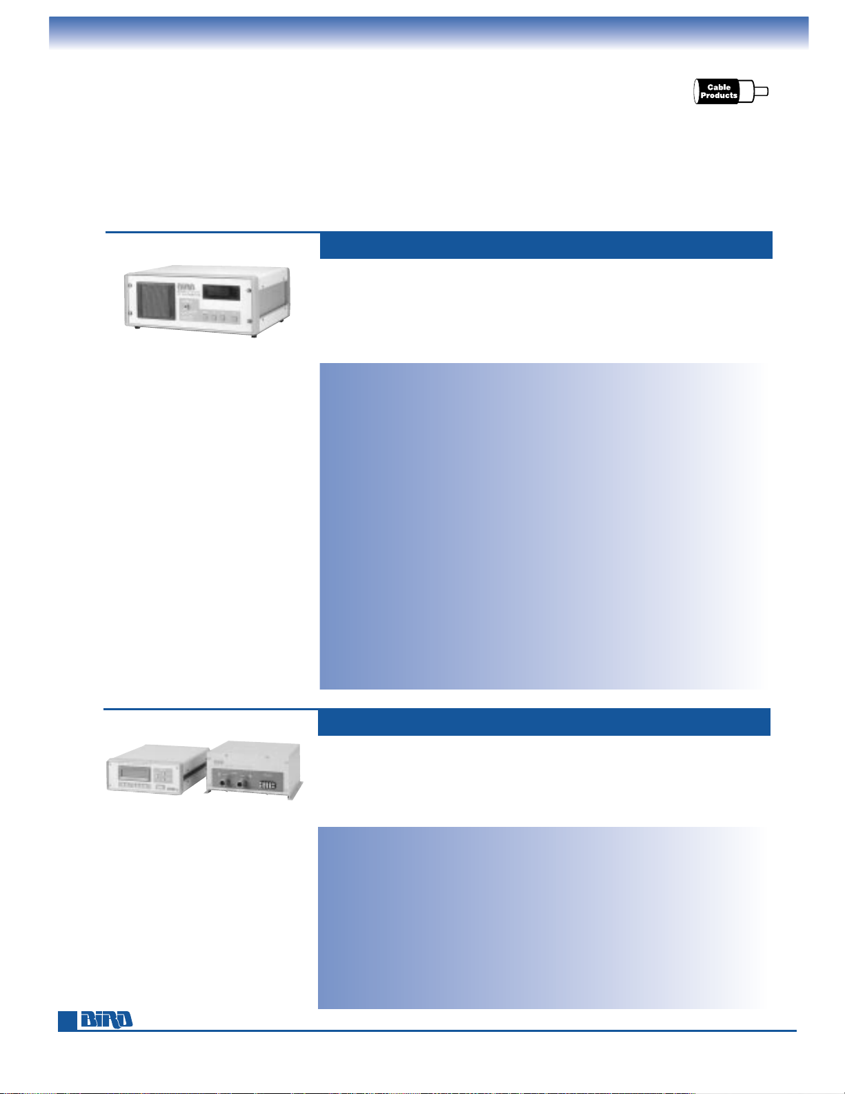
Our microprocessor controlled 6091 and 6085 Absolute Flow RF Calorimeters are
calibrated to a precision standard with the calibration profile in nonvolatile memory.
Measurements are automatically corrected prior to display and there’s no need for
calibration curves. A built-in interface lets you connect either calorimeter to any supported GPIB controller for remote or automated testing. Both units support IEEE-488.
The self-contained Model 6091 measures 10 to 200 watts at DC to 2.5 GHz with
±
1.25% of reading accuracy, and reaches 97% of the final reading in under
1 minute. Measurements are made by connecting the power source to the
Model 6091. Sensor circuitry and load are inside the calorimeter for convenient,
self-contained operation. The power reading is presented on a 4-digit LED display.
The Model 6091P is a panel-mount version.
SELF-CONTAINED CALORIMETER MODELS 6091, 6091P
HIGH-POWER CALORIMETER MODEL 6085
Models: 6091 and 6091P (panel mount)
Power Range: 10 W – 200 W (average power
independent of wave shape).
Frequency Range: Broadband; low-reflection
load remains precisely matched from
DC to 2.5 GHz.
Input VSWR: DC to 1 GHz: 1.10 max. (26.4 dB
min. return loss). 1 to 2.5 GHz: 1.25 max.
(19.18 dB min. return loss).
Accuracy: 10 W – 25 W: ±3% of reading.
25 W to 200 W: ±1.25% of reading.
Display/Functions: Large 4 digit, 7-segment
LED displays RF power directly in W.
The rise in coolant temperature (∆T) is
displayed in ˚C. Coolant flow rate is
displayed in liters/minute.
Calibration: Precalibrated to precision
power standard at factory, with data
stored in nonvolatile memory.
Response Time: 1 minute max. to reach
97% of final reading.
Sampling Rate: 1 reading/second.
Remote Operation: General Purpose Interface
Bus cable supplied, for connecting the
6091 to a GPIB controller. All front panel
features are available through the bus.
GPIB Functions Supported: SH1, AH1, T6, L4,
SR1, RL1, PP0, DC1, DT1, C0, E1, TE0, and
LE0. (IEEE 488 1978)
EMI: EMI compliance per FCC part 15J, Class A.
Coolant: 10 oz. (525 ml.) water-based coolant
(65% H
2
0 + 35% ethylene glycol).
Load: Specially designed 50-ohm precision
load resistor assembly.
Input Connector: Female Type N.
Nominal Input Impedance: 50 ohms.
Power: 104 to 132 Vac / 195 to 264 Vac,
47–63 Hz (single phase).
Power Consumption: 45–70 W
Temperature Range: Storage: 50˚ to 122˚F
(10˚ to 50˚C)
Operating: 59˚ to 95˚F (15˚ to 35˚C).
Nominal Size: (includes connector end drain)
Model 6091: 16
1
⁄2" L ×2015⁄32" W
×
817⁄16" H (419 mm ×520 mm ×210 mm)
Model 6091P: 16
1
⁄2" L ×2015⁄32" W
×
817⁄16" H (419 mm ×483 mm × 177 mm)
Weight: Model 6091: 40 lbs. (18.1 kg.)
Model 6091P: 25 lbs. (11.3 kg.)
Accessories: 61⁄2ft. (2 meter) GPIB cable,
AC power cord.
Power/Frequency Range: Function of RF
load, flow rate, temperature and coolant
Accuracy:
±
3% of reading
Circuitry: Microprocessor based operation
with digital display
Display/Functions: 31⁄2-digit LCD displays
power in W or dBm, (∆T) in ˚C, flow in
liters/minute, min., max., back light
Over-Range Protection: N/O and N/C
interlock on sensor
Ambient Temperature Range: 5˚C to 35˚C
Cable Length: 5 m standard
Water Flow: 4 to 72 liters/min.
(actual range determined by RF load)
Stabilization Time: 5 minutes typical
Coolant: Water/glycol
AC Power: 115/230 Vac, 50/60 Hz
Nominal Size: Meter: 129⁄32" L ×125⁄32" W
×
41⁄4" H (312 mm ×309 mm ×108 mm);
Power Sensor: 9
27
⁄32" L ×103⁄32" W
×
53⁄64" H (250 mm ×256 mm ×128 mm)
Weight: RF Power Meter: 9 lbs. (4 kg);
RF Power Sensor: 7 lbs. (3.2 kg)
Required Product: ECONOLOAD®Load
Resistor on pages 50–51, or other water
cooled external load
The Model 6085 consists of a digital RF power meter and an RF power sensor that
must be used with an ECONOLOAD
®
or other external water-cooled load. The load
connects to a sensor box which is digitally linked to the meter. It provides ±3% of
reading accuracy and fast stabilization. RS-232 (Model 6085A232) and IEEE-488
(Model 6085A488) Interface Cards are available.
Page 9
9
RF POWER METER
SELECTION GUIDE
Power Meters For Use With 50-Ohm Cable
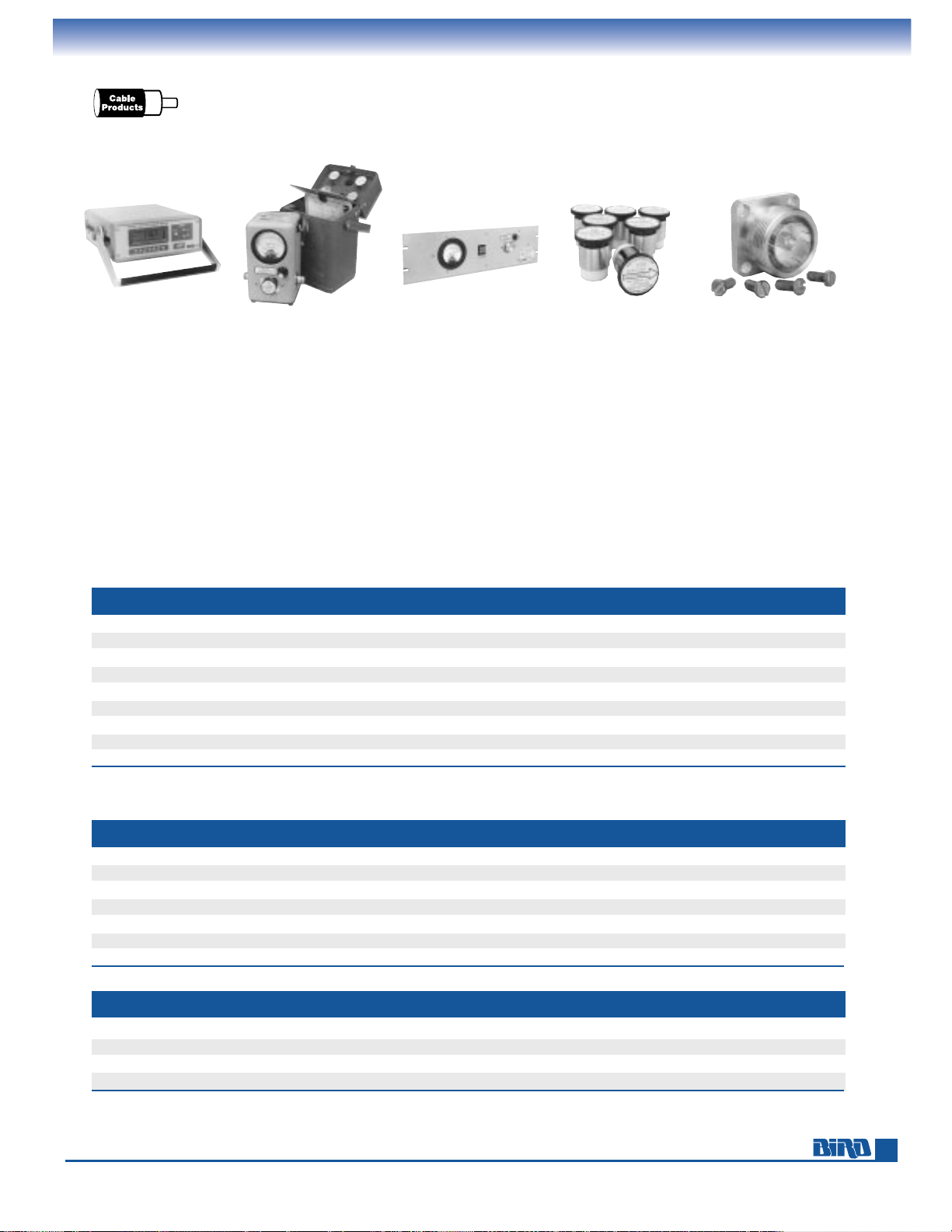
We’ve organized the power meters in this catalog into three major groups: wattmeters for use with 50-ohm cable and
7
⁄8” line
(pages 6-21), wattmeters for 1
5
⁄8”– 61⁄8” rigid transmission lines (pages 29–33) and absorption wattmeters (pages 39–41).
The tables below should help you identify the Bird 50-ohm cable power meter that’s best for your application. Then turn to
the referenced page for full product descriptions and specifications. You can also contact Bird or any authorized distributor
for further assistance.
Broadcast professionals and those needing power meters for rigid transmission lines should see the selection guide on
page 29. The absorption wattmeter selection guide is located on page 39.
PRECISION
INSTRUMENTS
Pages 6–8
PORTABLE MODELS
Pages 11–16, 21
CASES Page 24
TEST SETS Page 14
PANEL-MOUNT
MODELS
Pages 17–20
ELEMENTS
Pages 25–28
ACCESSORIES, PARTS,
AND QC CONNECTORS
Pages 23, 59–61
MODEL POWER FREQ. DISPLAY SEE
(SEE NOTE 1)
SPECIAL FEATURES
(WATTS) (MHz)
ACCURACY
TYPE PAGE
43* General purpose portable for 50-ohm AM, FM, CW, SSB. 0.1–10,000 0.45–2700
±
5% FS Analog 12
4308* Model 43-style for analog cellular systems. 1.5–50 440–960
±
5% FS Analog 15
4304A* Broadband operation. 5 ranges with single element. 5–500 25–1000
±
7% FS Analog 15
4431* Similar to Model 43, but with adjustable output RF tap. 0.1–5000 2–1000
±
5% FS Analog 14
4314B* PEP & peak-reading for navcom, radar, TV, telemetry, pulsed RF. 0.1–10,000 0.45–2700
±
5% FS Analog 13
4410-Series* High sensitivity, dynamic range and accuracy. Multirange elements. 0.002–10,000 0.2–2300
±
5% of rdg Analog 16
APM-16* Average-reading meter for analog and digital services. 1–1000 2–2300 4% rdg + 1% FS Analog 11
4305A* High-power version of Model 43 . 50–25,000 0.45–2300
±
5% FS Analog 14
4391A** High-speed CW, PEP and Peak pulse for pulsed RF, radar, TV, telemetry. 0.1–10,000 0.45–2700
±
5% FS Digital 21
Note 1: * = Portable THRULINE®style instrument with internal line section and QC connectors.
** = POWER ANALYST
®
style instrument with digital display and pushbutton controls.
PANEL-MOUNT – For Control Racks and Permanent Installations
POWER FREQ. DISPLAY SEE
MODEL SPECIAL FEATURES
(WATTS) (MHz)
ACCURACY
TYPE PAGE
4527 Dual elements, dual meters and fixed RF tap. For 2-way mobile radio. 0.1–1,000 2–512
±
5% FS Analog 17
4521 Single meter with single rotatable element (rack-mount Model 43). 0.1–10,000 0.45–2700
±
5% FS Analog 17
4522 Dual elements with single, switchable meter. 0.1–10,000 0.45–2700
±
5% FS Analog 17
4526 Dual elements and dual meters for simultaneous fwd and refl readings. 0.1–10,000 0.45–2700
±
5% FS Analog 17
3128A Forward and reflected power monitor/alarm; 43-type elements. 0.1–10,000 0.45–2700
±
5% FS Analog 19
3170A High-speed, forward and reflected power monitor/alarm; 43-type elements. 0.1–10,000 0.45–2700
±
5% FS Analog 20
4201-Series 12 or 24 channel, dual meters 0.1–10,000 0.45–2700
±
5% FS Analog 18
PRECISION INSTRUMENTS – For Laboratories, Research, and Other High-Accuracy Applications
POWER FREQ. DISPLAY SEE
MODEL SPECIAL FEATURES
(WATTS) (MHz)
ACCURACY
TYPE PAGE
4420 Direct reading of power, VSWR, return loss. Uses external sensor. 0.1–10,000 0.1–2500
±
3% of rdg. Analog 7
4421 Direct reading of power, VSWR, return loss. Uses external sensor. 0.1–10,000 0.1–2500
±
3% of rdg. Digital 6
6085 Calorimeter with separate power sensor. Use with external load. See Note 2 See Note 2
±
3% of rdg. Digital 8
6091 Calorimeter. Broadband, high accuracy, self contained. 10–200 DC–2500
±
1.25% of rdg. Digital 8
50-OHM CABLE WATTMETERS –
Portable — For Service and Field Use
Note 2: Model 6085 is used with a separate ECONOLOAD®. Load determines power and frequency range. Typical capability > 10kW.
Page 10
Phone: 440-248-1200 • Fax: 440-248-5426
10
THRULINE®WATTMETERS DELIVER
RF POWER MEASUREMENTS YOU CAN TRUST
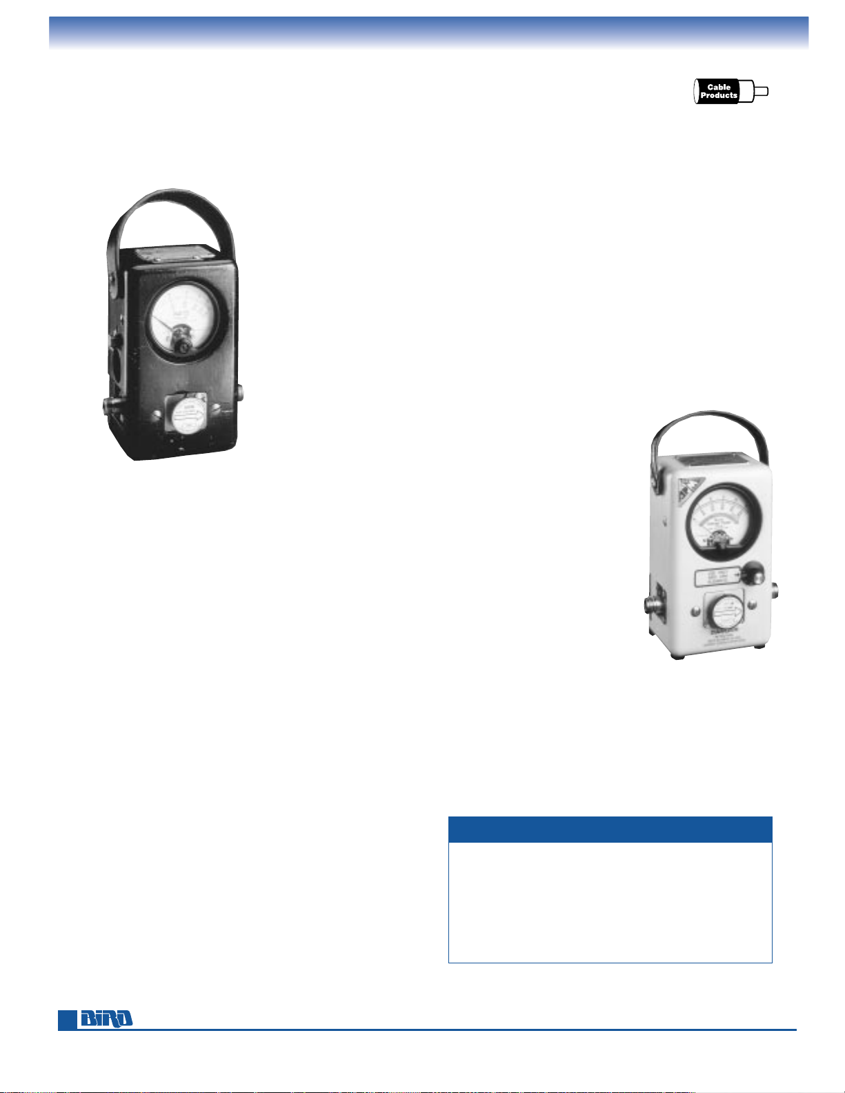
The development of the first Bird Model 43 THRULINE
®
Wattmeter in 1952 heralded a major breakthrough in
the search for a solution to quickly and easily measure
radio-frequency power. It is difficult
today to realize that for most
of the first half century of radio
communications, the most
basic parameters of broadcasting could be measured only
by tedious and painstaking
procedures. While transmit
power could be derived via
RF voltage measurements
or calorimetry, neither procedure could measure reflected
power in real-world antenna
systems. Slotted-line devices
could be used to derive
VSWR, but their operation
was exacting, time consuming,
and often imprecise.
The Model 43 revolutionized
power measurement by
providing a means to measure
FORWARD and REFLECTED
power flow in a coaxial transmission line that was both
elegant in concept and simple
in application.
■
Just connect the THRULINE®Wattmeter into the coaxial
line, using readily interchangeable RF connectors.
■
Insert a precalibrated element into the THRULINE
®
sample port to define the power and frequency range.
■
Rotate the element to the stop to select the direction
of power flow to be measured.
■
Energize the line and take a reading.
A difficult task became exceptionally simple.
Accurate, dependable and ruggedly built to last. The
Model 43 quickly became the preferred method for measuring RF power in coaxial transmission lines and made
±
5% of full scale the new standard of accuracy. And the
Model 43’s rugged construction spawned a legendary
reputation for performing under the toughest conditions.
While we strongly discourage abuse of this precision
instrument, stories abound of Model 43’s that survived drops
from towers, immersion in floods, falls from moving vehicles
and, in at least one instance, the weight of a bulldozer.
Our 1995-1996 search for vintage units yielded numerous
Model 43’s from Bird’s initial 1952 product run that were
still in regular use. Justin Dennis, the owner of the oldest
instrument we located, captured the essence of the Model
43 when he told us “If it says 80 watts, it’s 80 watts.”
Power meters for every application. Today, Bird offers a
wide selection of general and special purpose RF power
VINTAGE 43 WATTMETER
This well used Model 43
from Bird’s first production
run still delivers accurate
measurements today. It was
donated to Bird in 1996
by Justin Dennis.
We’ve included selection guides in this catalog to help
you quickly zero-in on the right wattmeter for your
application. Bird’s expert staff is ready to assist you.
FINDING THE RIGHT POWER METER
meters. The single element Model 4304A and Model 4308
offer a wide-frequency range, multiple power ranges and
±
6 to 7 percent of full- scale accuracy. The industry standard
Model 43, with its several variations, still provides the pace
setting ±5% of full-scale accuracy. For even more precision,
choose from the 4410 Series with their multirange elements
and ±5% of reading accuracy. The highest accuracy available
today in THRULINE
®
technology is the digital display 4421
Laboratory Grade Wattmeter, which offers ±3% of reading
accuracy, automatically computes VSWR, displays power in
either watts or dBm and retains minimum and maximum
readings in memory.
Other THRULINE
®
Power Meters and test sets are available
to measure peak envelope power, pulsed RF, avionic and
television power levels. Bird also offers a full range of
fixed communications site monitoring instruments, from
wattmeters for use with up to 6
1
⁄8" broadcast lines to our
multifunction WATTCHER
®
RF Monitors.
State-of-art power meters for PCS
and more.
Our newest wattmeter,
the Advanced Power Measurement
Model APM-16, is specially designed
for use on today’s digitally modulated RF communication systems.
The APM-16 combines proven
THRULINE
®
technology with stateof-art circuitry to take average
power readings of CDMA, FDMA,
GSM, TDMA, and other digital
technologies used in today’s
cellular, PCS, and similar systems.
Whether your next purchase
is the new Model APM-16, a
WATTCHER
®
RF Monitor or any
Bird product, you can be confident
it will perform exactly as you’d
expect. Every unit we build today
contains the same care and pride
that went into our 1952 vintage
Model 43s that still give their
owners dependable power
measurements over 40 years later.
Product Page
Meters for 50-ohm cable and 7⁄8” line. . . . . . . . . . . . . . . . . . . . . 9
Meters for 1
5
⁄8”– 61⁄8” line . . . . . . . . . . . . . . . . . . . . . . . . . . . . . 29
Absorption wattmeters . . . . . . . . . . . . . . . . . . . . . . . . . . . . . . . 39
APM-16
The new Model APM-16
accurately measures
complex digital as well
as analog signals.
Page 11
THRULINE
®
RF DIRECTIONAL WATTMETERS
Advanced Power Measurement For Digital RF Signals
11
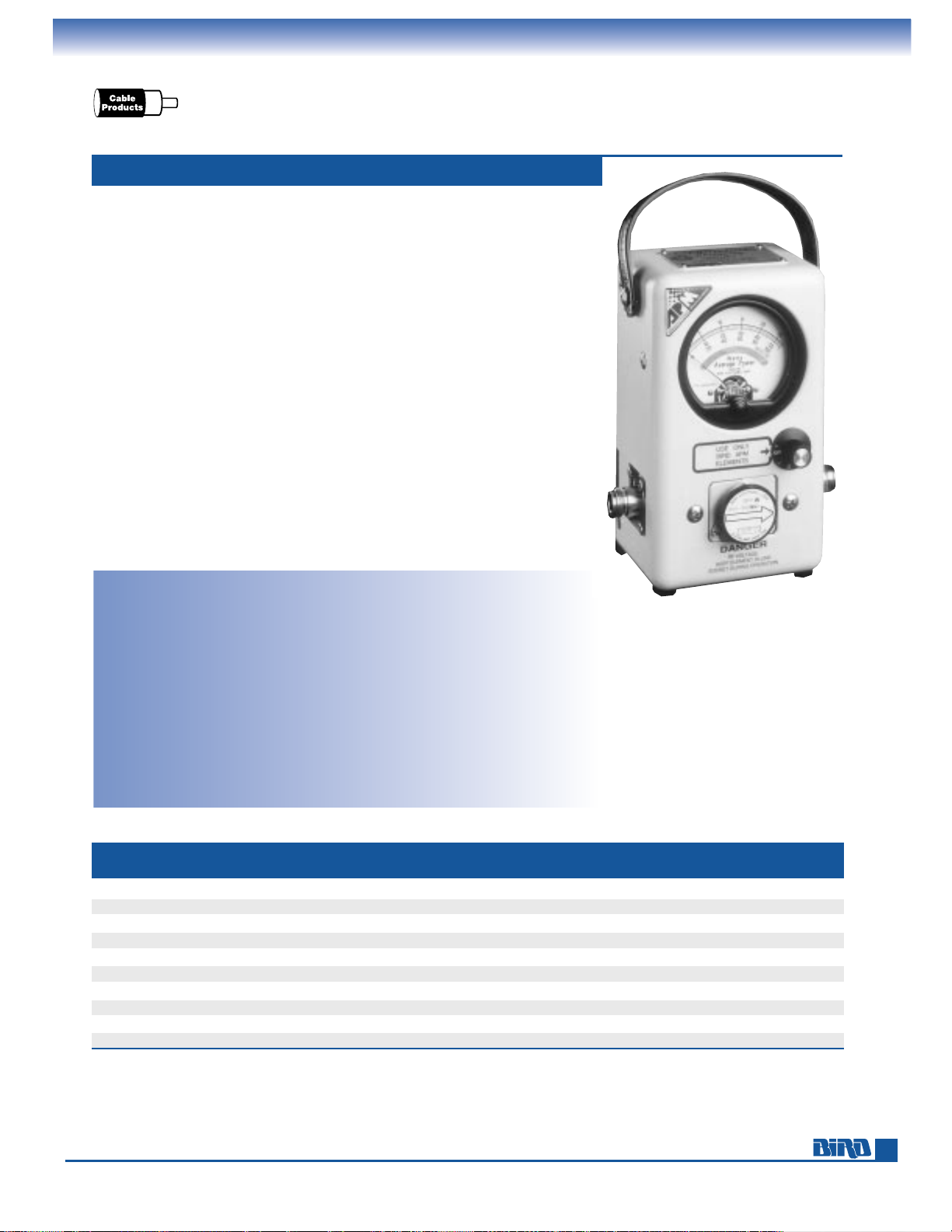
Bird developed the APM-16 for engineers and technicians who work with today’s
increasingly common digital RF technology systems. The complex waveforms of
many PCS, cellular, and other digitally-encoded services can depart significantly
from AM, FM, and CW, making power measurement difficult and uncertain. The
APM-16 meets the challenge by delivering precise average power readings for
virtually any digital or analog system.
New APM series plug-in elements cover 2 through 2300 MHz and 1 through
1000 watts. Read forward or reflected power instantly by simply rotating the
element. The shock-mounted meter features a linear scale with mirror band to
improve reading accuracy. Interchangeable QC connectors add to the APM-16’s
versatility.
The APM-16’s high-accuracy, broad power/frequency handling, interchangeable
connectors, and capability to measure digital and analog signals give you an
instrument that will handle almost any RF power measurement application.
■
Accurately measures complex digital and analog RF signals.
■
Ideal for multicarrier transmission systems.
■
Easy-to-use. Operates just like any THRULINE®wattmeter.
■
Versatile plug-in elements cover all your present and future needs.
■
Ruggedly constructed and truly portable for demanding field use.
AVERAGE-READING POWER METER MODEL APM-16
Power Range: 1 W to 1000 W
Frequency Range: 2 MHz to 2.3 GHz
Accuracy:
10° to 35° C±4% reading, ±1% full scale
–20° to 50° C±6% reading, ±2% full scale
Peak/Avg. Ratio: In excess of 10 dB
Insertion VSWR: (with N connector)
1.05 max. to 1000 MHz
Settling Time: < 1 second
Meter: Shock mounted, linear scale with
expanded scales of 25, 50 and 100 for
full scale 1 to 1000 W readings.
Mirrored scale includes 5% overrange.
Temp. Ranges: –20° to 50° C operating;
–25° to 65° C storage
Humidity: 95% ±5% max. (noncondensing)
EMC: Complies with 92/31/EEC. Emissions,
EN55011; Immunity: EN-50082-2 at 10 V/M.
Safety: Complies with EN61010-1
Battery: Internal 9 volt ”transistor“
(NEDA No. 1604A) (100 hour life min.)
Connectors: QC Type
(Female N normally supplied)
Finish: Beige powder coat
Nominal Size: 67⁄8" L ×51⁄8" W ×35⁄8" D,
(175 mm
×
130 mm ×92 mm)
Weight: 3 lbs. (1.4 kg)
Elements: Special APM Series
Recommended Accessories: Case (page 24),
spare battery (page 61),
extra QC connectors (page 60)
Protect your wattmeter and organize accessories with a sturdy case. See page 24.
FREQUENCY BANDS (MHz)
POWER
2- 25- 50- 100- 200- 400- 950- 1100- 1700- 2200-
RANGE
30 60 125 250 500 1000 1260 1800 2200 2300
1W — APM-1A APM-1B APM-1C APM-1D APM-1E APM-1J APM-1K APM-1L APM-1M
2.5W — APM-2.5A APM-2.5B APM-2.5C APM-2.5D APM-2.5E APM-2.5J APM-2.5K APM-2.5L APM-2.5M
5 W APM-5H APM-5A APM-5B APM-5C APM-5D APM-5E APM-5J APM-5K APM-5L APM-5M
10 W APM-10H APM-10A APM-10B APM-10C APM-10D APM-10E APM-10J APM-10K APM-10L APM-10M
25 W APM-25H APM-25A APM-25B APM-25C APM-25D APM-25E APM-25J APM-25K APM-25L APM-25M
50 W APM-50H APM-50A APM-50B APM-50C APM-50D APM-50E APM-50J APM-50K APM-50L —
100 W APM-100H APM-100A APM-100B APM-100C APM-100D APM-100E APM-100J — — —
250 W APM-250H APM-250A APM-250B APM-250C APM-250D APM-250E APM-250J — — —
500 W APM-500H APM-500A APM-500B APM-500C APM-500D APM-500E — — — —
1000 W APM-1000H APM-1000A APM-1000B APM-1000C APM-1000D APM-1000E — — — —
APM ELEMENTS FOR APM-16
Page 12
Phone: 440-248-1200 • Fax: 440-248-5426
12
Product Page
Batteries. . . . . . . . . . . . . . . . . . . . . . . . . . . 61
Cables, Meter . . . . . . . . . . . . . . . . . . . . . . 61
Cases . . . . . . . . . . . . . . . . . . . . . . . . . . . . . 24
Connector Adapter Kits . . . . . . . . . . . . . . 61
Elements (required on some models) . 25 – 28
Use the table below to quickly find products to enhance the versatility of your
THRULINE
®
Wattmeter.
Product Page
Field-Strength Element. . . . . . . . . . . . . . . 22
Loads/Terminations. . . . . . . . . . . . . . . . . . 42
Meter Movements . . . . . . . . . . . . . . . . . . 23
Peak Power Kit for Model 43. . . . . . . . . . 13
QC Connectors . . . . . . . . . . . . . . . . . . . . . 60
THRULINE
®
RF DIRECTIONAL WATTMETERS
Model 43, Accessory Guide
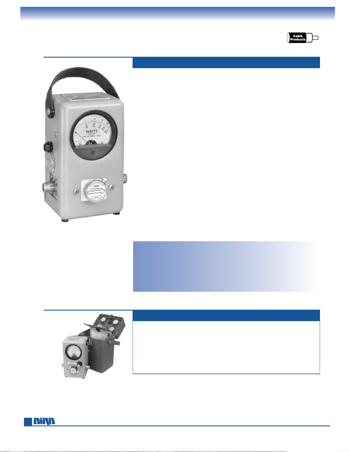
The Model 43 THRULINE®Directional Wattmeter accurately measures forward or
reflected power in coaxial transmission lines under any load condition. Each Model
43 consists of a line section, ”QC“ (Quick Change) connectors and an indication
meter housed in a rugged, corrosion-resistant aluminum case.
The line section is a high-precision 50-ohm coaxial air line that inserts between
the transmitter and the antenna or load. A socket is provided in each line section
for a plug-in element with the desired power rating and frequency range. Line
section ends are equipped with ”QC“-type connectors.
The Model 43 is supplied with two female ”N“-type ”QC“ connectors. These connectors can be interchanged in the field without affecting instrument calibration.
The instrument’s indicating meter is a shock-mounted 30-microampere meter with
scales of 25, 50, and 100; permitting full-scale direct-power reading from 100 milliwatts to 10,000 watts.
Plug-in elements determine the power rating and the frequency range, and these
values are marked on each element. The elements rotate to read both forward and
reflected power. There is no need for calibration charts or instrument adjustments.
Elements can be purchased at any time and replaced in the field. For added convenience, Model 43 connectors and elements are interchangeable with many other
Bird wattmeters.
Remote installation can easily be achieved by removing the Model 43‘s RF line
section and inserting it at any desired point in the line. For best visibility, the meter
itself can be relocated using the 32-inch meter cable supplied in the instrument
housing. Additional meter cable lengths can be ordered separately.
Power Range: 100 mW to 10 kW using
Bird Plug-in Elements.*
Frequency Range: 450 kHz to 2.7 GHz
(depending on element)
Insertion VSWR: with N Connectors
1.05 max. to 1000 MHz
Accuracy:
±
5% of full scale
Connectors: QC Type
(Female N normally supplied)
THE INDUSTRY STANDARD MODEL 43
ACCESSORIES, OPTIONS AND PARTS
Finish: Light Gray powder coat
Nominal Size: (includes connectors)
6
7
⁄8" H ×51⁄8" W ×35⁄8" D,
(175 mm
×
130 mm ×92 mm)
Weight: 3 lbs. (1.4 kg)
Optional Case: See page 24
Elements: Tables 1, 2, 3, 3A, 4, 6
on pages 25 – 26
Protect your wattmeter with
a sturdy case. Shown is a CC-1
carrying case with elements
and Model 4410 Series Wattmeter.
Over 250,000
Model 43 wattmeters
have been produced!
*
Quoted accuracy only when used with other Bird products.
Page 13
E-mail: [email protected] • Internet: www.bird-electronic.com
SSB AM
CWFM
PULSE
13
THRULINE
®
RF DIRECTIONAL WATTMETERS
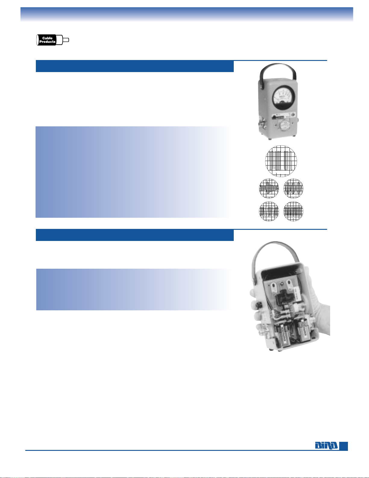
Peak-Reading Wattmeter, Peak Kit for Model 43
In 15 minutes, with no soldering, adapt your Model 43 wattmeter to read true peak
power output at ±8% of full-scale accuracy. The following specifications are as
installed in a Bird Model 43.
Power Range: 100 mW to 10 kW using
Bird Plug-in Elements.*
Frequency Range: 450 kHz to 2.7 GHz
(depending on element)
Accuracy: CW mode: ±5% full scale
Peak mode: ±8% full scale
PEAK POWER RETROFIT KIT MODEL 4300-400
Modulation: Normal voice audio; or
(Peak Mode) Rectangular pulses
Duty cycle 2% (min)
Repetition rate 100 pps (min)
Pulse width 200 µs (min)
Battery Life: 48 hours typical
Weight: Adds 1 lb. to Model 43
Portable peak-reading instrument designed specifically for measurement of air
navigational aids and other pulsed RF systems — such as telemetry, radar, television,
and command and control — as well as peak envelope power (PEP) measurement
of SSB and AM signals. Measures practically any type of 50-ohm coaxial transmission:
pulsed, AM, FM, CW.
An improved power system using two internal, 9-Volt alkaline, transistor batteries
enhances portability. An AC power adapter is also supplied.
Power Range: 100 mW to 10 kW using
Bird Plug-in Elements*
Frequency Range: 450 kHz to 2.7 GHz
(depending on element)
Insertion VSWR: (with N connectors)
1.05 max. to 1000 MHz
Accuracy:
±
5% of full-scale CW, ±8% PEP
Pulse Parameters: (min.) Pulse width 0.4 µs
(100-2300 MHz), 1.5 µs
(26–99 MHz) and 15 µs (2–25 MHz);
repetition rate 30 pps and duty factor
1
× 10–4min.
Battery: Two 9-Volt alkaline transistor batteries
Battery Life: 20 hours of operation, typical
AC Power: (using Bird adapter) 120 Vac,
60 Hz or 220 Vac, 60 Hz
PEP WATTMETER MODEL 4314B
Connectors: QC Type
(Female N normally supplied)
Finish: Light Gray powder coat
Nominal Size: (includes connectors)
6
7
⁄8" H × 51⁄8" W × 35⁄8" D,
(175 mm
× 130 mm × 92 mm)
Weight: 3 lbs. (1.4 kg)
Elements: Tables 1, 2, 3, 3A, 4, 5, 6
on pages 25 – 26
Recommended Accessories: Case (page 24),
spare batteries (page 61),
extra QC-connectors (page 60).
* Quoted accuracy only when used with other Bird products.
Accurately measure power in digital RF technology systems with our new APM-16
Advanced Power Measurement Wattmeter. See page 11.
Page 14
Phone: 440-248-1200 • Fax: 440-248-5426
14
THRULINE
®
RF DIRECTIONAL WATTMETERS
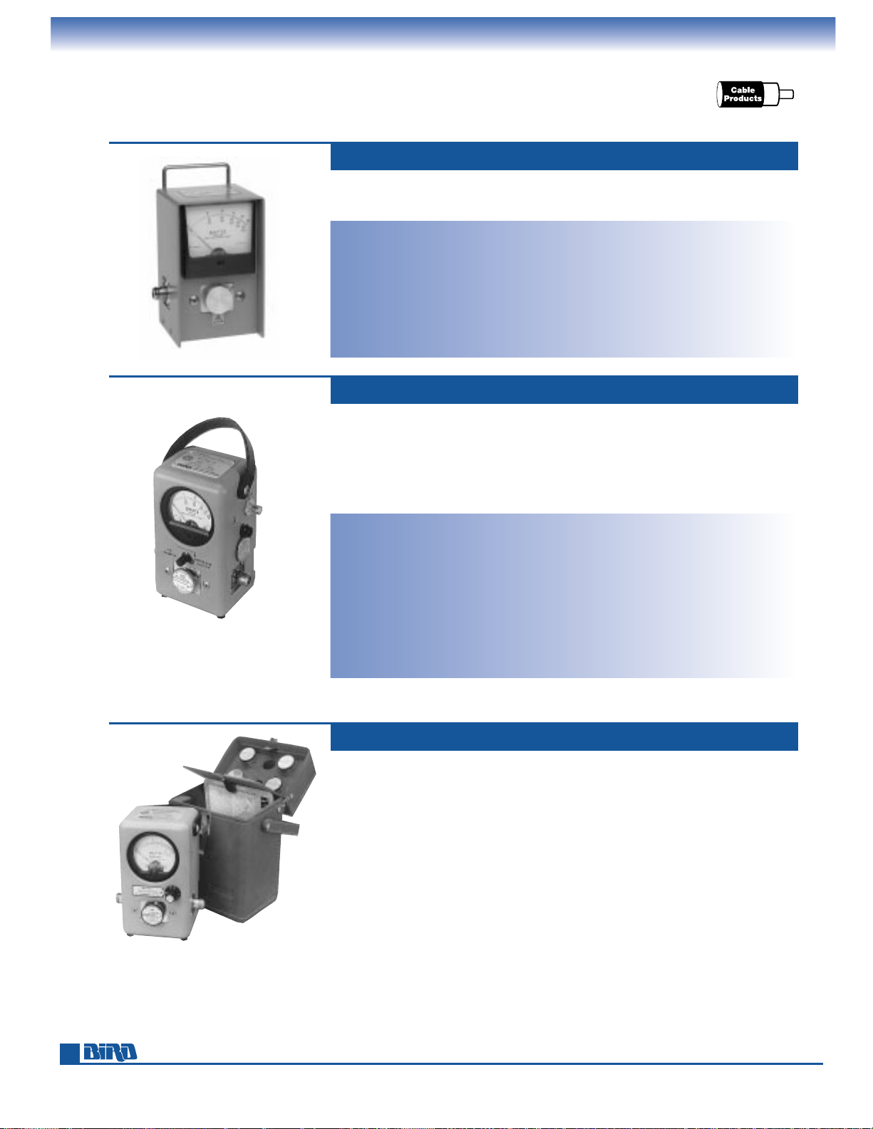
High-Power, RF Tap
The Model 4305A provides the ±5% of full-scale accuracy of the Model 43,
but offers extended power handling to 25 kW.
Power Range: 50 W to 25 kW using Bird
Plug-in Elements**
Frequency Range: 450 kHz to 2.3 GHz
(depending on element)
Insertion VSWR: with N connectors 1.05 max.
Accuracy:
±
5% of full scale
Connectors: QC Type
(Female N normally supplied)
Finish: Gray powder coat
HIGH-POWER WATTMETER MODEL 4305A
Nominal Size: (includes connectors)
6
5
⁄16" H × 51⁄8" W × 41⁄4" D,
(161 mm
× 131 mm × 108 mm )
Weight: 31⁄4lbs. (1.5 kg)
Elements: Tables 8, page 27 and 15⁄8" AA,
page 37
Recommended Accessories: Case (page 24),
extra QC connectors (page 60).
The combination Model 4431 THRULINE®Wattmeter provides the advantage of
an RF signal sample (for use with counters, oscilloscopes, spectrum analyzers, etc.)
at the same time a power measurement is made. Amplitude of the RF sample is
readily adjusted by a signal-coupling control knob mounted on the front of the
wattmeter case. Uses the same plug-in elements as the Model 43 Wattmeter within
its frequency and power ratings.
Power and Frequency Range: 5 kW max.
2 to 30 MHz, 1 kW max. 30 to 1000
MHz* using Bird Plug-in Elements**
Insertion VSWR: with N connectors
1.07 max.* to 1000 MHz
Accuracy:
±
5% of full scale
Insertion Loss: 0.1 dB max. (2–512 MHz);
0.2 dB max. (512–1000 MHz)*
RF Sample Output: Variable –15 to –70 dB
from BNC (Female) port
Connectors: QC Type
(Female N normally supplied)
VARIABLE RF TAP MODEL 4431
Finish: Gray powder coat
Nominal Size: (includes connectors)
6
7
⁄8" H × 51⁄8" W × 35⁄8" D,
(175 mm
× 130 mm × 92 mm)
Weight: 31⁄2lbs. (1.6 kg)
Elements: Tables 1, 2, 3, 3A, 4, 6 on
pages 25 – 26 (within power/frequency
range limits stated above)
Recommended Accessories: Case (page 24),
extra QC connectors (page 60).
See page 60 for a wide selection of QC connectors.
Our wide selection of power meters, elements, cases, loads, and other accessories
can be combined into a power measurement test set that’s perfect for you.
Please contact your local sales office to have a test set custom-tailored to your
exact requirements.
CUSTOM TEST SETS
* Applies only when coupling is less than 30 dB.
** Quoted accuracy only when used with other Bird products.
Page 15
E-mail: [email protected] • Internet: www.bird-electronic.com
15
THRULINE
®
RF DIRECTIONAL WATTMETERS
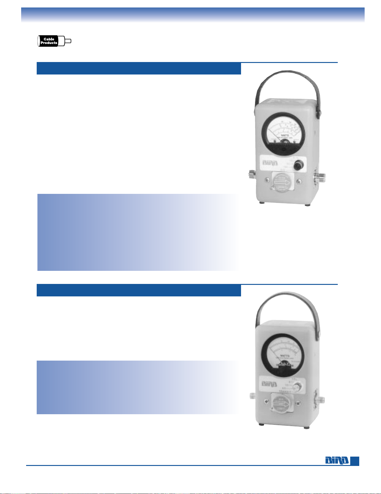
Broadband, Multirange Wattmeters
The Model 4304A wattmeter is a popular choice of wireless communications
professionals. This rugged instrument is ideal for anyone who needs to quickly
test multiple power and frequency ranges. The versatile 4304A uses a single,
permanently mounted, 25–1000 MHz element to deliver full-scale measurements
from 5 to 500 watts. A high-quality line section keeps insertion loss to less than
0.10 dB from 25–512 MHz and 0.13 dB from 512–1000 MHz. The resulting full-scale
accuracy of ±6 to 7% (depending on frequency) is ideal for many two-way
communications applications.
Performance is stable to 1000 MHz. Insertion VSWR with the supplied N female
connectors is a maximum of 1.12 at 512–1000 MHz and will not exceed 1.08 VSWR
at 25–512 MHz.
Operation is exceptionally easy. Select the power range you want to measure
with the 5-position power selector switch. Forward and reflected power are
then measured by simply rotating the element. A chart mounted to the back
of the instrument lets you easily determine antenna or load VSWR from power
measurements.
Power Ranges: 5, 15, 50, 150, 500 W,
with no scale limitations except power
limited to 150 W from 800–1000 MHz
Frequency Range: 25 MHz to 1.0 GHz
Insertion VSWR: 25–512 MHz, 1.08 max.
(with UHF female conn.) 512–1000 MHz,
1.12 max.
Insertion Loss: 25–512 MHz, 0.10 dB max.
with UHF female conn. 512–1000 MHz
range, 0.15 dB max.
FIXED 25–1000 MHz, 5–500 WATT ELEMENT MODEL 4304A
Accuracy: 25–100 MHz, ±7% of full scale,
using correction charts. 100–512 MHz,
±
6% of full scale, no correction needed.
512–1000 MHz, ±7% of full scale, no
correction needed.
Connectors: QC Type
(Female N normally supplied)
Finish: Light Gray powder coat
Nominal Size: 67⁄8" H × 51⁄8" W × 35⁄8" D,
(175 mm
× 130 mm × 92 mm)
Weight: 3 lbs. (1.36 kg)
Recommended Accessories: Case (page 24),
extra QC-connectors (page 60).
Need to measure complex digital technology signals? See the new APM-16 on page 11.
The Model 4308 was designed to provide easy ±5% full-scale accurate measurements
of analog cellular systems and subscriber equipment. If you work with digital cellular,
we recommend the APM-16 found on page 11 that handles both digital and analog
RF technologies.
A permanently mounted element and 4-position power selector switch facilitate
measurements of 1.5, 5, 15, or 50 watts full-scale from 440 to 960 MHz. This instrument is also a good choice for low-to-medium power measurements in the UHF and
800–960 MHz bands.
Power Ranges: 1.5, 5, 15, 50 W, with
no scale limitations
Frequency Range: 440–960 MHz
Insertion VSWR: 1.05 with TNC connectors
(QC type)
Accuracy:
±
5% of full scale
Impedance: 50 ohms, nominal
Connectors: QC Type
(Female TNC normally supplied)
CELLULAR SPECIALIST WATTMETER MODEL 4308
Finish: Gray powder coat
Nominal Size: 67⁄8" H × 51⁄8" W × 35⁄8" D,
(175 mm
× 130 mm × 92 mm)
Weight: 3 lbs. (1.36 kg)
Recommended Accessories:
CC-1 case (page 24).
Page 16
Phone: 440-248-1200 • Fax: 440-248-5426
16
THRULINE
®
RF DIRECTIONAL WATTMETERS
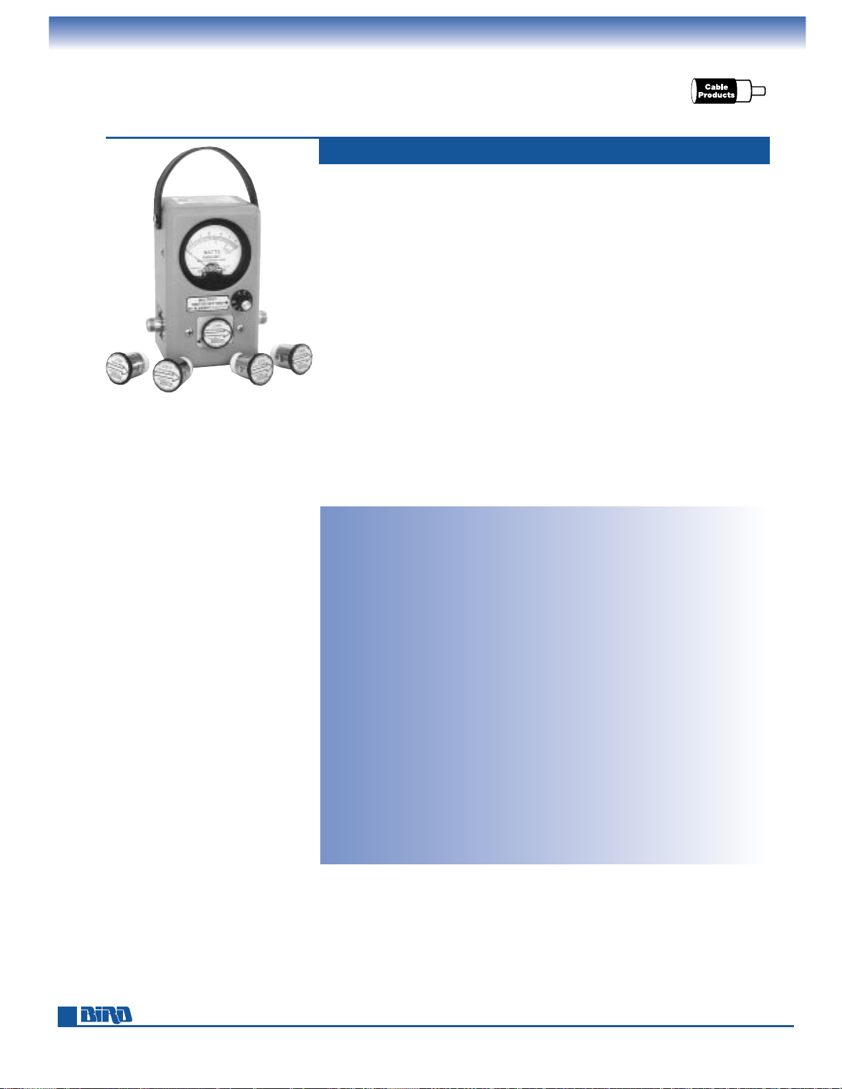
Multipower Level, Superior Sensitivity
Our 4410 Series high-sensitivity wattmeters are solid choices for field-service applications where the greater dynamic range of the plug-in elements substantially reduces
the number of elements needed to cover multiple power and frequency ranges.
The 4410 series is also well-suited to laboratory work where power levels as low
as 2 milliwatts must be measured with high accuracy.
Each 4410 Series wattmeter plug-in element is capable of reading seven different
power ranges covering 0.002* to 10,000 watts. The power ranges of the different
elements overlap and include: 0.002–10 W, 0.02–100 W, 0.2–1000 W and 2–10,000 W.
All ranges are in frequency bands from 200 kHz to 2300 MHz. Any one of the seven
power ranges is selected by a rotary switch located on the front of the wattmeter.
Forward and reflected power measurements are accomplished by rotating the
element. See Element Tables 9 through 12 on page 27.
Exceptional ±5% of reading accuracy is achieved via a built-in temperature compensation circuit. This stated accuracy applies from 100% of full scale down to 20%
of full scale across all seven ranges.
Two portable models are available:
Model 4410A powered by a 9-volt alkaline, transistor-type, battery.
Model 4412 AC powered with rechargeable NiCd battery.
Models: 4410A and 4412
Power Range: 2 mW to 10 W, 20 mW to
100 W, 200 mW to 1 kW or 2 W to
10 kW full scale in one single Plug-in
Element. Any Bird Series 4410-Element
may be used.
Frequency Range: 200 kHz to 2.3 GHz CW
or FM.
Insertion VSWR: with N Connectors 1.25 max.
to 2300 MHz
Accuracy:
±
5% of reading for any reading
above 20% of the Power Range selected
for FM or CW signals without AM. This
accuracy is maintained for a full 37 dB
dynamic range with each 4410 Element
(except No. 4410–1 200 kHz–535 kHz
which is accurate to ±10% of reading,
and 4410-15 1.0–1.8 GHz and 4410-16
1.8–2.3 GHz which are accurate to ±8%
of reading.)
Ambient Temperature Range: Elements
4410-1 through –8 and –10 through –16
are temperature compensated for rated
accuracy from 0˚C to 50˚C (32˚ to 122˚F),
and 4410-20 through 27 from 20˚C to
30˚C (68˚ to 86˚F).
MULTIPOWER, ±5% READING ACCURACY 4410 SERIES
Over-Range Protection: To 120% of nominal
full scale (i.e. 12 W, 120 W, 1,200 W, or
12,000 W). No damage or degradation
to the unit will result, regardless of the
Range Selector Switch position.
Battery Life: Model 4410A: 24 hrs.
min. with standard 9 V alkaline
“transistor” battery (NEDA No. 1604A
supplied). Model 4412: 7 hrs. min.
(rechargeable).
AC Power: Models 4412:
105
−125/210−250 Vac, 50/60 Hz
with integral selector switch
Connectors: QC Type
(Female N normally supplied)
Finish: Gray powder coat
Nominal Size: (includes connectors)
6
7
⁄8" H × 51⁄8" W × 35⁄8" D,
(175 mm
× 130 mm × 92 mm)
Weight:
Model 4410A: 3 lbs. (1.4 kg).
Model 4412: 3
1
⁄3lbs. (1.5 kg)
Elements: Tables 9, 9A, 10, 11, 12 on page 27
Recommended Accessories: Case (page 24),
spare battery (page 61), extra QCconnectors (page 60).
* On the 10 mW scale
Need even greater accuracy? See our laboratory grade instruments on pages 6–8.
Each 4410 Series
power element has seven
overlapping power levels
to reduce the number
of elements you need.
Page 17
17
THRULINE
®
RF DIRECTIONAL WATTMETERS
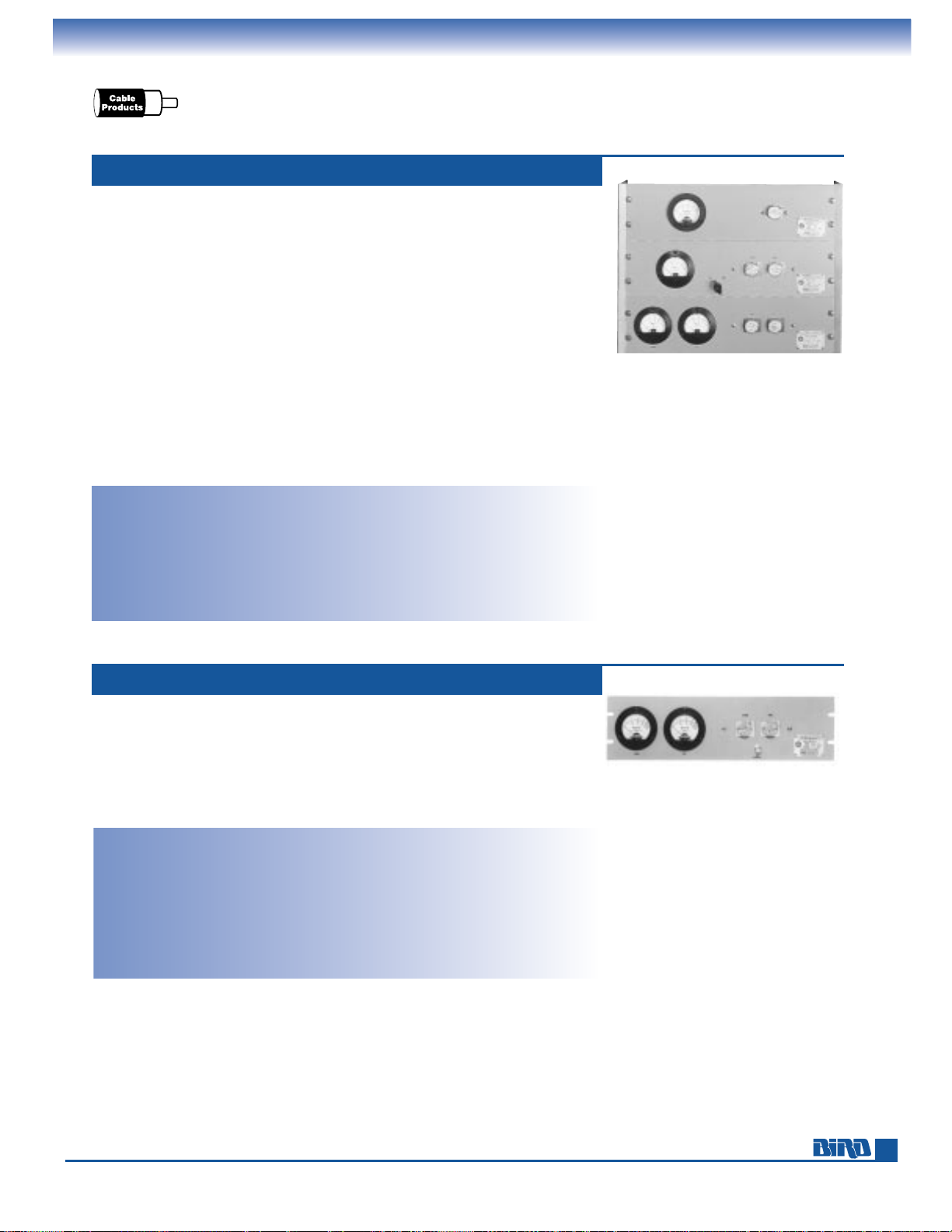
Panel-Mount Wattmeters with Line Sections
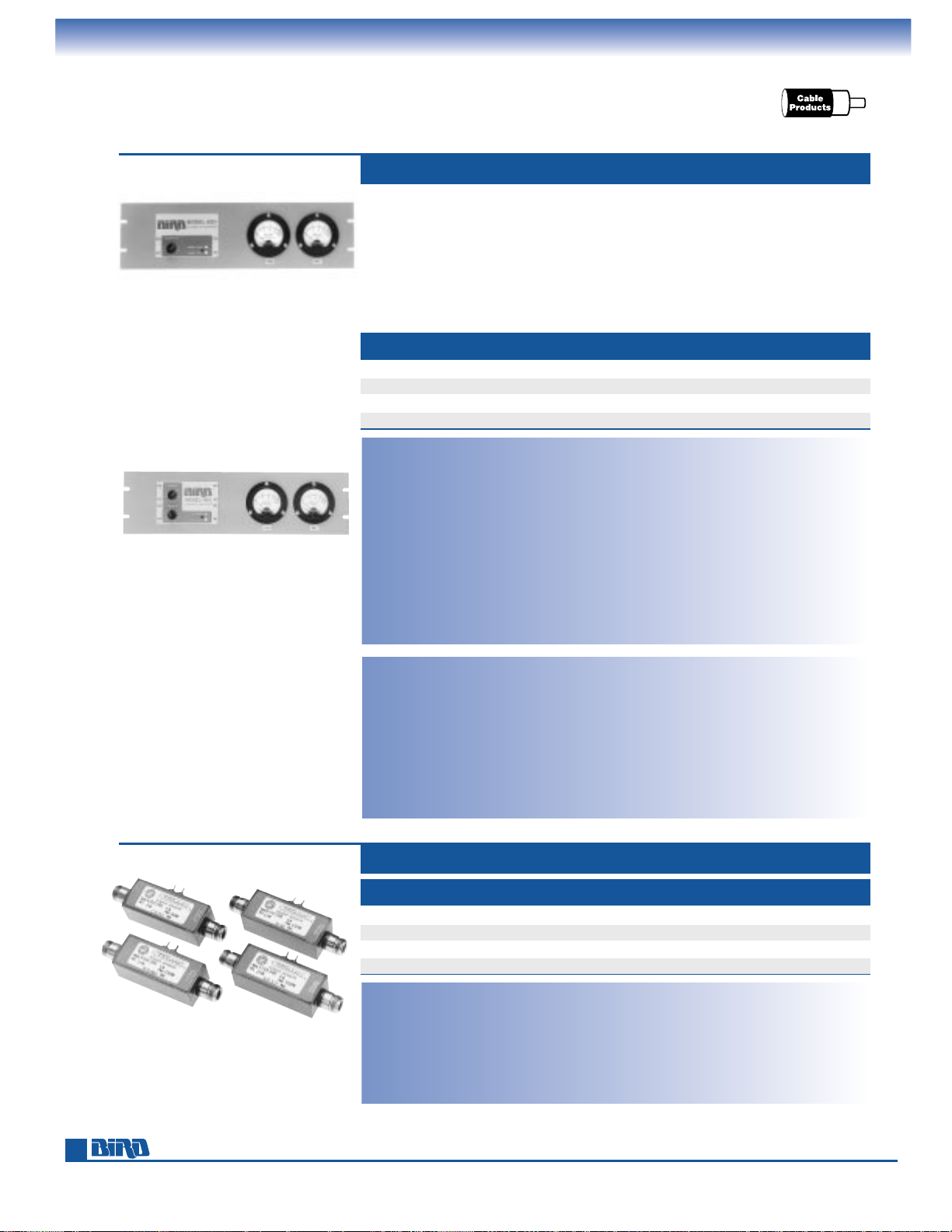
Bird’s 4500 Series wattmeters are panel-mount versions of the time-tested Model 43
wattmeter. They will measure power in CW and FM systems that employ 50-ohm
cable or
7
⁄8" EIA transmission line. All models include a precision line section and
either one or two 3-scale analog meters to give you full-scale direct readings from
100 mW to 10 kW. The rack panel fits standard 19-inch equipment racks. Plug-in
elements — the same used with the Model 43 — are sold separately. Depending
on the element selected, Models 4521, 4522 and 4526 will cover frequencies from
0.45 to 2700 MHz. Measurement accuracy is ±5% of full scale.
The Model 4521 has a single element socket and meter. Forward and reflected
power are measured by rotating the element.
The single-meter Model 4522 has two element sockets. The second socket permits
the use of a more sensitive element to measure reflected power and let you more
accurately determine VSWR. A selector switch changes the display between forward
and reflected power.
In addition to the sensitivity advantage provided by two element sockets, the dual
meter Model 4526 simultaneous displays forward and reflected RF power.
Models: 4521, 4522, 4526
Power Range: 100 mW to 10 kW using
Bird Plug-in Elements.*
Frequency Range: 450 kHz to 2.7 GHz
(depending on element)
Insertion VSWR: with N Connectors
1.05 max. to 1000 MHz
Accuracy:
±
5% of full scale
0.45–2700 MHz MODELS 4521, 4522, AND 4526
Connectors: QC Type
(Female N normally supplied)
Finish: Gray powder coat
Nominal Size: 19" W × 57⁄32" H × 111⁄16" D,
(483 mm
× 133 mm × 43 mm)
Weight: 31⁄2 lbs. (1.6 kg)
Elements: Tables 1, 2, 3, 3A, 4, 6
on pages 25 – 26
Power Range: 100 mW to 1 kW using
Bird Plug-in Elements.*
Frequency Range: 2 to 512 MHz
(depending on element)
Insertion VSWR: with N Connectors
1.05 max. to 512 MHz
Accuracy:
±
5% of full scale
RF Sample Output: Fixed at –53 dB from
512 to 10 MHz, decreasing to –70 dB
at 2 MHz BNC (Female) port
Connectors: QC Type
(Female N normally supplied)
Finish: Gray powder coat
Nominal Size: 19" W × 57⁄32" H × 111⁄16" D,
(483 mm
× 133 mm × 43 mm)
Weight: 31⁄2lbs. (1.6 kg)
Elements: 2 to 512 MHz models within
Tables 1, 2, 6 on pages 25–26
* Quoted accuracy only when used with other Bird products.
Wattmeters for rigid line use are on pages 29–33 and 35.
Top to Bottom:
MODELS
4521, 4522, 4526
The panel-mount Model 4527 is tailored for 2-way mobile applications in the
2–512 MHz range. Like the Model 4526 described above, it has dual-element sockets and meters. These features let you determine VSWR more precisely via using a
more sensitive reflected power element, and simultaneously read forward and
reflected power. In addition, an RF sampling output (female BNC) is included.
Select elements up to 1000 watts from 2 – 200 MHz and up to 500 watts
from 200 – 512 MHz.
2–512 MHz WITH SAMPLER PORT MODEL 4527
MODEL 4527
Page 18
Phone: 440-248-1200 • Fax: 440-248-5426
18
12 AND 24 CHANNEL POWER METERS 4201 SERIES
THRULINE
®
RF DIRECTIONAL WATTMETERS
Multichannel Power Meters
MODEL 4201A503
24 Channel RF Power Meter
Models: 4201A501, 4201A502
Power Range: 10 mW to 10 kW using Bird
Plug-in Elements*
Frequency Range: 450 kHz to 2.7 GHz
(depending on elements)
Accuracy:
±
5% of full scale
Meter Scales: FWD and RFL 25, 50,
and 100 W
Meter Sensitivity: 30 µA/1400Ω
Front Panel Controls: One or two rotary
channel selector switches, channel A/B
push-button on 24 channel, enable/
disable push-button on 12 channel.
Connectors: RCA phono jacks
Finish: Gray powder coat
Nominal Size: 19" W × 57⁄32" H × 5" D,
(483 mm
× 133 mm × 127 mm)
Weight:
4201A501: 33⁄4lbs. (1.7 kg)
4201A502: 2
7
⁄8lbs. (1.3 kg)
Required Products:
Line Section: 4230-053 or 4522-002-5
on page 23
Elements: Tables 1, 2, 3, 3A, 4, 6
on pages 25–26
Cables: 10 ft. – 4201A008-1, 15 ft. –
4201A008-2, 25 ft. – 4201A008-3
Models: 4201A503, 4201A504
Power Range: Sensor dependent
Frequency Range: Sensor dependent
Accuracy:
±
5% of full scale
Meter Scales: FWD and RFL 15, 30, and 60 W
Meter Sensitivity: 30 µA/1400Ω
Front Panel Controls: One or two rotary
channel selector switches, channel A/B
push-button on 24 channel, enable/
disable push-button on 12 channel.
Connectors: RCA phono jacks
Finish: Gray powder coat
Nominal Size: 19" W × 57⁄32" H × 5" D,
(483 mm
× 133 mm × 127 mm)
Weight:
4201A503: 33⁄4lbs. (1.7 kg)
4201A504:2
7
⁄8lbs. (1.3 kg)
Required Products:
Power Sensor: Order from below
Cables: 10 ft. – 4201A007-1, 15 ft. –
4201A007-2, 25 ft. – 4201A007-3
Insertion VSWR: 1.1 max.
Insertion Loss: 0.2 dB
Directivity: 25 dB min.
Accuracy:
±
5% of full scale
Connectors:
RF Input: Female N
RF Output: Female N
DC Outputs: Solder Lugs
Finish: Gray powder coat
Nominal Size: (includes connectors)
4
1
⁄2" W × 11⁄4" H × 1" D,
(114 mm
× 32 mm × 25 mm)
Weight: 4.5 oz. (128 grams)
POWER SENSORS FOR 4201A503/4201A504
Need to measure complex digital technology signals? See the new APM-16 on page 11.
MODEL CHANNELS METER SCALE EACH TRANSMITTER REQUIRES
4201A501 24 25/50/100 W Dual Line Section and Elements
4201A502 12 25/50/100 W Dual Line Section and Elements
4201A503 24 15/30/60 W Power Sensor
4201A504 12 15/30/60 W Power Sensor
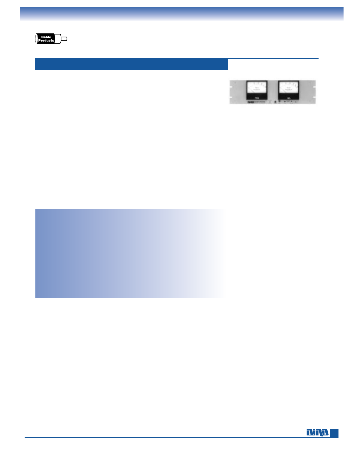
The 4201 Series panel-mount wattmeters make it easy to measure RF power
in cellular sites and two-way radio base stations that have multiple transmitters.
You can monitor up to 24 transmitters by simply turning a channel-selector knob
on the front panel. Dual meters simultaneously display forward and reflected
power at ±5% full scale accuracy.
Power Sensors (see below) or Plug-in Elements determine frequency and power
ranges. Each transmitter requires a power sensor or a dual-socket line section with
two elements.
FORWARD POWER REFLECTED POWER FREQUENCY
MODEL
MAXIMUM MAXIMUM RANGE
4152-220 150 W 15 W 30 – 88 MHz
4163-240 150 W 15 W 118 – 250 MHz
4164-240 150 W 15 W 420 – 512 MHz
4169-300 60 W 6 W 805 – 960 MHz
MODEL 4201A504
12 Channel RF Power Meter
* Quoted accuracy only when used with other Bird products.
Page 19
E-mail: [email protected] • Internet: www.bird-electronic.com
19
THRULINE
®
RF DIRECTIONAL WATTMETERS
WATTCHER®RF Monitoring System
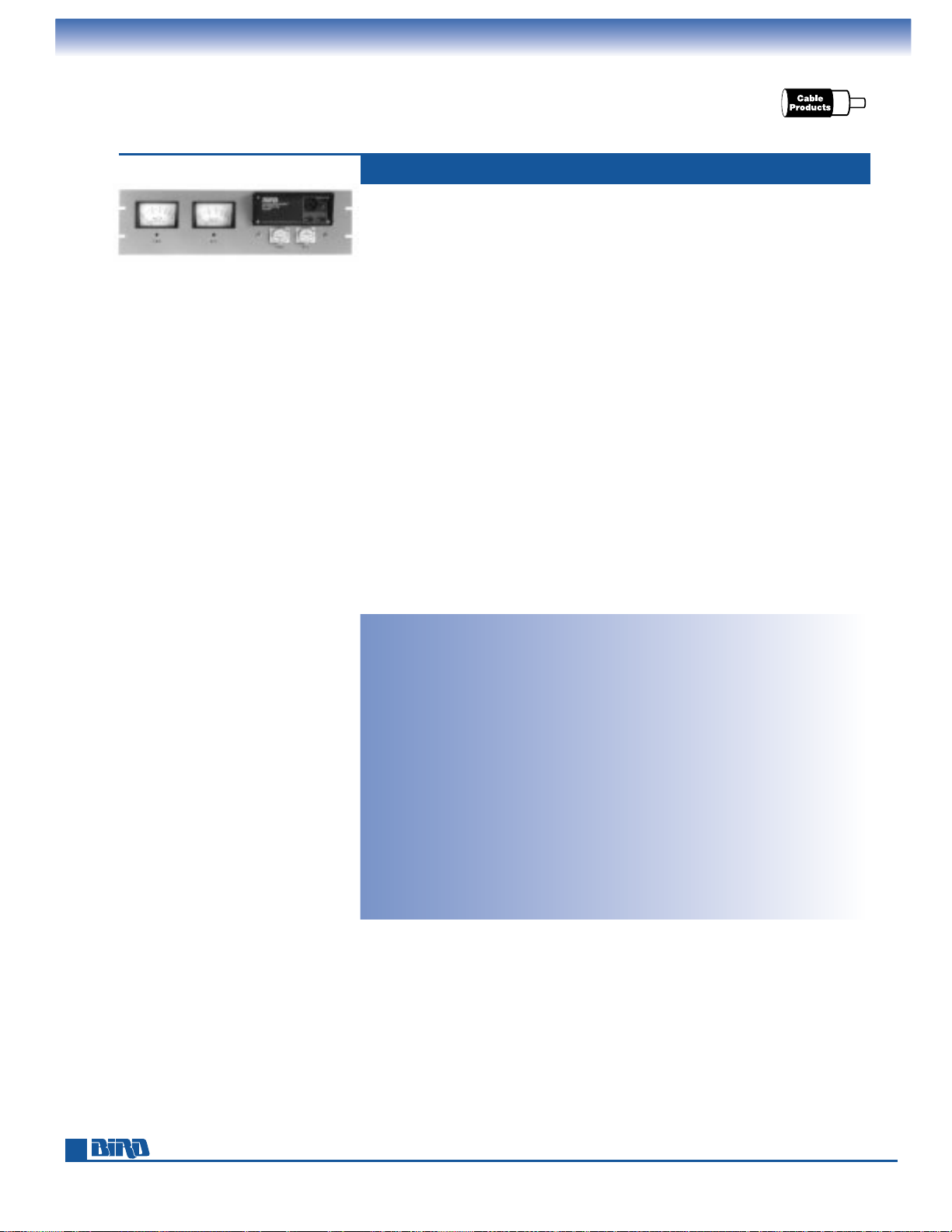
The Model 3128A WATTCHER®RF monitoring and alarm system can automatically
activate a variety of safety and equipment protection measures when it detects
an abnormal antenna system load condition. The 3128A WATTCHER
®
simultaneously displays forward and reflected power for 100 mW to 10 kW
systems and signals audible and visual alarms if reflected power exceeds the limit
you set for more than 50 ms. The instrument’s DPDT interlock relay can also be
wired to shutdown the transmitter, activate de-icing equipment, signal a remote
alarm and initiate other measures to protect your equipment from high VSWR.
Some important Model 3128A features include:
■
Mirrored scale meters aid reading and help eliminate parallax.
■
Separate push-button reset control and LED indicators added.
■
Improved circuitry reduces the chance of false alarms.
■
Can be wired for automatic, unattended reset
when alarm condition clears.
■
Rear connection panel speeds installation or removal.
■
Tested and found EMC compliant.
Power Range: 100 mW to 10 kW using Bird
Plug-in Elements*
Frequency Range: 450 kHz to 2.7 GHz
Accuracy:
±
5% of full scale
Meter Scales: FWD and RFL 25, 50, and 100 W
Meter Sensitivity: 30 µA/1400 Ω
Alarms: Front-panel buzzer and red LED
Front Panel Controls: Reset push-button,
reflected power limit display button,
adjust alarm level recessed screw
Rear Panel Features: FWD/RFL DC signal
inputs (BNC), DC power/remote reset
connector, DPDT interlock relay connector,
fail-safe/nonfail-safe selector, alarm
buzzer disable, AC line voltage selector,
safety fuses and IEC 320 AC receptacle.
100 mW – 10 kW WATTCHER
®
MODEL 3128A
Cable: Includes two 25 ft. DC cables
AC Power: 115/230 Vac, 50/60 Hz, @ 0.125A
DC Power: 9 – 16 Vdc @ 1A
Finish: Gray powder coat
Nominal Size: 19" W × 57⁄32" H × 33⁄4" D,
(483 mm
× 133 mm × 95 mm)
Weight: 5 lbs. (2.28 kg)
Required Products:
Line Section: 4230-053 or 4522-002-5
from page 23
QC Connectors: Two from page 60
Elements: Two from Tables 1, 2, 3, 3A,
4 or 6 on pages 25-26
* Quoted accuracy only when used with other Bird products.
WATTCHERS for 250 – 100,000 watt rigid line systems are found on pages 32–33.
MODEL 3128A
Features a reflected
power alarm
Page 20
Phone: 440-248-1200 • Fax: 440-248-5426
20
THRULINE
®
RF DIRECTIONAL WATTMETERS
High-Speed WATTCHER®RF Monitoring System
Our Model 3170A WATTCHER®gives you ultra fast response time and a forward
power drop-off alarm in addition to the capabilities of the Model 3128A. It also
includes a line section complete with two QC-type N (Female) connectors to insert
in your coaxial transmission line, and handles power from 100 mW to 10 kW.
This RF monitoring system can protect your transmitting equipment from damage —
and loss of air time — when faults cause high-standing waves. It can warn a remote
operator of: 1) low power due to detuning, component deterioration, or AC line
difficulties, and 2) high reflected power due to factors such as antenna icing,
transmission line problems, physical accidents and lightning strikes. The solid state
Model 3170A:
■
Displays a continuous, simultaneous view of forward and reflected power
which can be remoted.
■
Provides fast-fault response time — 250 times faster than other monitors —
for forward and reflected power monitoring.
■
Alerts you to forward power drop-off below a set level
(e.g. to conform to appropriate FCC requirements).
■
Activates audible/visual alarms when reflected power increases.
■
Allows remote reset in the event of a false alarm or momentary
disturbance which leaves transmission unimpaired.
■
Operates from AC or DC.
Power Range: 100 mW to 10 kW using
Bird Plug-in Elements*
Frequency Range: 450 kHz to 2.7 GHz
Insertion VSWR: with N connectors 1.05 max.
to 1000 MHz, 1.1 max. to 2700 MHz
Accuracy:
±
5% of full scale
Meter Scales: FWD and RFL 25, 50,
and 100 W
Alarms: Front-panel buzzer, “Active”
and “Trip” LEDs for forward/reflected
Response Time: 25 µs max.
Activate Forward: 73 µs to 50 ms
nominal (adjustable) monitor delay
Front Panel Controls: Reset push-button,
adjust FWD/RFL alarm levels screw,
element sockets
Rear Panel Features: DC FWD/RFL signal
inputs, main and remote meter drive
outputs, external 12–16 Vdc supply input,
alarm in/out, reset in/out, AC line voltage
selector, fuse, IEC 320 AC receptacle.
HIGH SPEED, FWD/RFL ALARM WATTCHER
®
MODEL 3170A
Inputs/Outputs: TTL compatible +5 V logic.
Outputs for remote meter
AC Power: 115/230 Vac, 50/60 Hz, @ 56 mA
DC Power: 12.7 to 16.0 Vdc @ 400 mA max.
Connectors: QC Type
(Female N normally supplied)
Finish: Gray powder coat
Nominal Size: 19" W × 57⁄32" H × 95⁄16" D,
(483 mm
× 133 mm × 237 mm)
Weight: 7 lbs. (3.2 kg)
Required Products:
Elements: Two from Tables 1, 2, 3, 3A,
4 or 6 on pages 25–26
* Quoted accuracy only when used with other Bird products.
WATTCHERS for 250 – 100,000 watt rigid line systems are found on pages 32–33.
MODEL 3170A
Features 25 µs response,
forward and reflected
power alarms
Page 21
21
THRULINE
®
RF DIRECTIONAL WATTMETERS
Multifunction RF POWER ANALYST
®
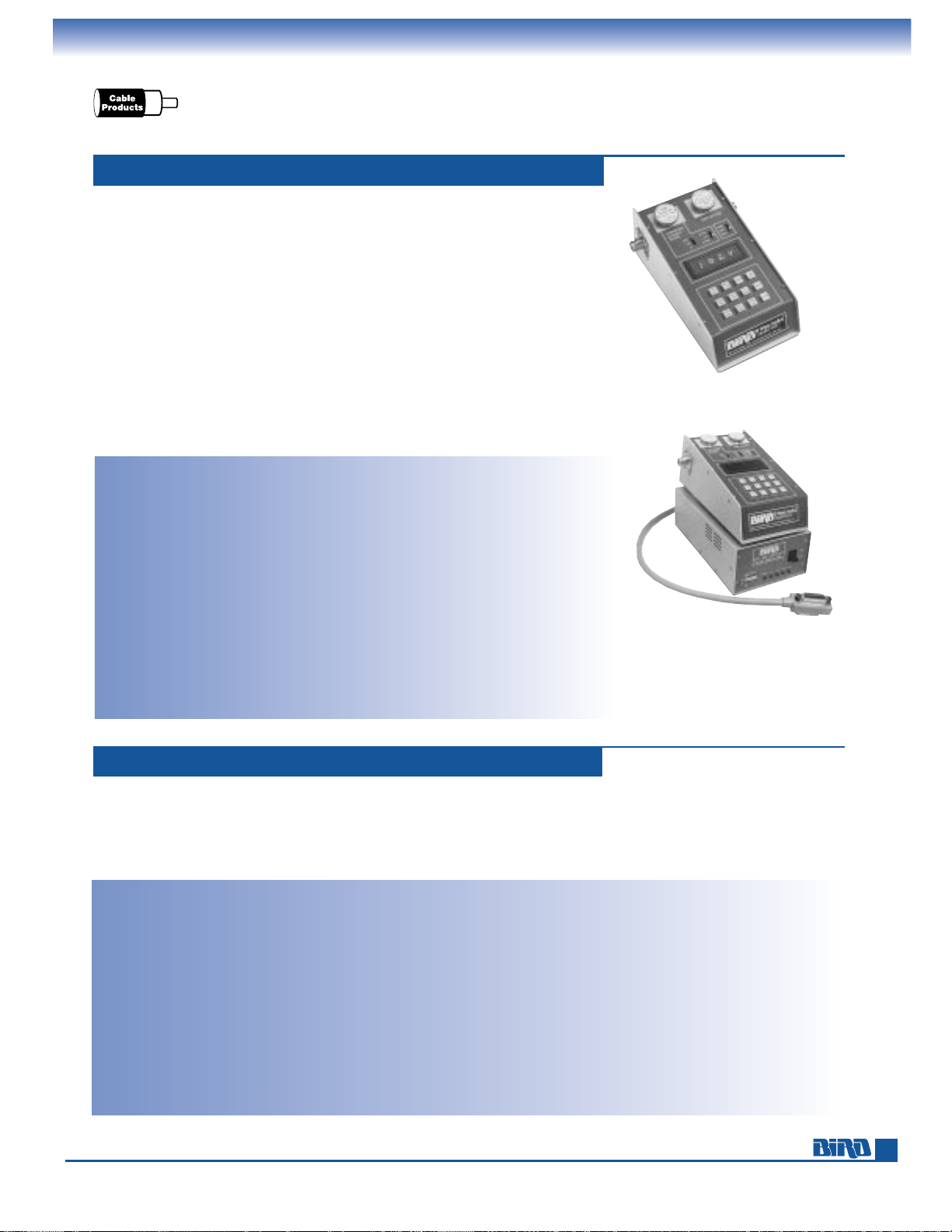
The ruggedly built, multifunction Model 4391A RF POWER ANALYST®features a
digital display, microprocessor-based operation, and simplified, push-button control.
This wattmeter is well suited to C
3
, telemetry, two-way communications, avionics
and radar, as well as standard radio and television applications.
■
Frequency: 0.45 to 2700 MHz. Power: 100 mW to 10 kW
with 20% over-range.
■
Reads forward and reflected CW or FM power in watts or dBm,
Peak Envelope Power of SSB/DSB and symmetrical AM in watts,
and peak power for pulses as narrow as 0.8 µs.
■
Calculates SWR, return loss in dB and % modulation
■
Stores peak and null readings to facilitate adjustment
of maximum and minimum signal levels.
■
Shock-resistant keyboard and range switches. RFI protection.
Built-in international power supply/charger.
Model: 4391A
Power Range: 100 mW to 10 kW using
Bird Plug-in Elements*
Frequency Range: 450 kHz to 2.7 GHz
Insertion VSWR: with N Connectors
1.05 max. to 1000 MHz
Accuracy: Power Readings:
±
5% of full scale
CW, ±8% PEP;
VSWR:
±
10% of reading
% Modulation: (CW power
1
⁄3 or more of
full scale) ±5% (0–90%), ±10% (90–100%)
Usable Over-range: to 120% of scale
(CW, PEP, SWR and Return Loss)
Sampling Rate: 2 to 3 readings per second
Display: 31⁄2digit, 0.3" LED strobed
Modulation Frequency: 25 to 10,000 Hz (Audio)
Pulse Parameters: (min.) Pulse width 0.8 µs
(100–2700 MHz), 1.5 µs
(26–99 MHz) and 15 µs (2–25 MHz);
RUGGED, PEP RF POWER ANALYST
®
MODEL 4391A
Repetition Rate 25 PPS, and Duty Factor
1 x 10
–4
min.
Return Loss:
±
0.3 dB to corresponding
SWR value
Battery Life: 8 hours (rechargeable)
AC Power: 100–130/200–260 V, 50/60 Hz, 6 W
Connectors: QC Type
(Female N normally supplied)
Finish: Blue vinyl with silver anodized side panels
Nominal Size: (includes connectors)
9
9
⁄16" L × 57⁄32" W × 45⁄16" H
(243 mm
× 158 × 110 mm)
Weight: 53⁄4lbs. (2.6 kg)
Elements: Select 2 elements in a 10:1 power
ratio from Tables 1, 2, 3, 3A, 4, 5, 6 and
14 on pages 25 – 28.
Recommended Accessories: Case (page 24).
IEEE-488 Model: 4380A-488
Output: 31⁄2digit ASCII format
Logic Levels: Meets all IEEE standards 488-1978 specifications
GPIB Capabilities: Supports AH1, SH1, T5, L4 SR1, RL0, PP0, DC1,
DT1, C0 and E1
Environment: Operating temperature range 0˚C to +50˚C.
Storage temperature range –40˚C to +100˚C
AC Power: 100–130/200–260 Vac 50/60 Hz
Dimensions and Weight: 53⁄8" L × 31⁄4" W × 101⁄2" H
(137 mm
× 82 mm × 267 mm); 2 lb. 10 oz. (1.2 kg)
Output Connector: 24-pin IEEE-488 standard connector
Cable Supplied: 20 in. interconnecting cable to Bird
RF POWER ANALYST
®
Optional Cables: 31⁄4ft. (1 m) IEEE-488 bus interface cable, P/N
5-1317-1; 6
1
⁄2ft. (2 m) IEEE-488 bus interface cable, Bird P/N
5-1317-2; Use of longer bus interface cables is not recommended.
RS-232 Model: 4380A-232
Output: 31⁄2digit ASCII format
Logic Levels: Meets all EIA standard RS-232C specifications
Environment: Operating temperature range 0˚C to +50˚C.
Storage temperature range –40˚C to +100˚C
AC Power: 100–130/200–260 Vac 50/60 Hz
Dimensions and Weight: 53⁄8" L × 31⁄4" W × 101⁄2" H
(137 mm
× 82 mm × 267 mm); 2 lbs. 10 oz. (1.2 kg)
Output Connector: Standard 25-pin subminiature D style RS-232
Cable Supplied: 20 in. interconnecting cable to Bird RF
POWER ANALYST
®
Optional Cables: 5 ft. (1.5 m) RS-232 bus interface cable,
Bird P/N 5-1662-1; 10 ft. (3 m) RS-232 bus interface cable,
Bird P/N 5-1662-2.
* Quoted accuracy only when used with other Bird products.
MODEL 4391A
Our interface units (IEEE-488 shown above or RS-232) let
you remotely control a POWER ANALYST
®
Wattmeter’s
functions. Either interface requires a 15-pin connector on
the rear of any Model 4380/4390 Series wattmeter. The
connector and internal cabling are installed in a new
Model 4391A POWER ANALYST
®
, or in older wattmeters
having the suffix -832 in the Model number (e.g. Model
4391-832). Any 4380/4390 Series Wattmeter you already
own without this connector can be retrofitted at our plant.
BUS INTERFACE UNITS MODELS 4380A-488, 4380A-232
MODEL 4391A
AND 4380A-488
(Model 4380A-488 IEEE-488
interface unit described below.)
Page 22
Phone: 440-248-1200 • Fax: 440-248-5426
FREQUENCY MHz
COUPLING
MAX
MIN
2 5 10 20 50 100 200 500 1000
– 30 dB
– 40 dB
– 50 dB
– 60 dB
– 70 dB
– 80 dB
FREQUENCY MHz
COUPLING
MAX
MIN
2 5 10 20 35 50
–30 dB
–40 dB
–50 dB
–60 dB
–70 dB
–80 dB
22
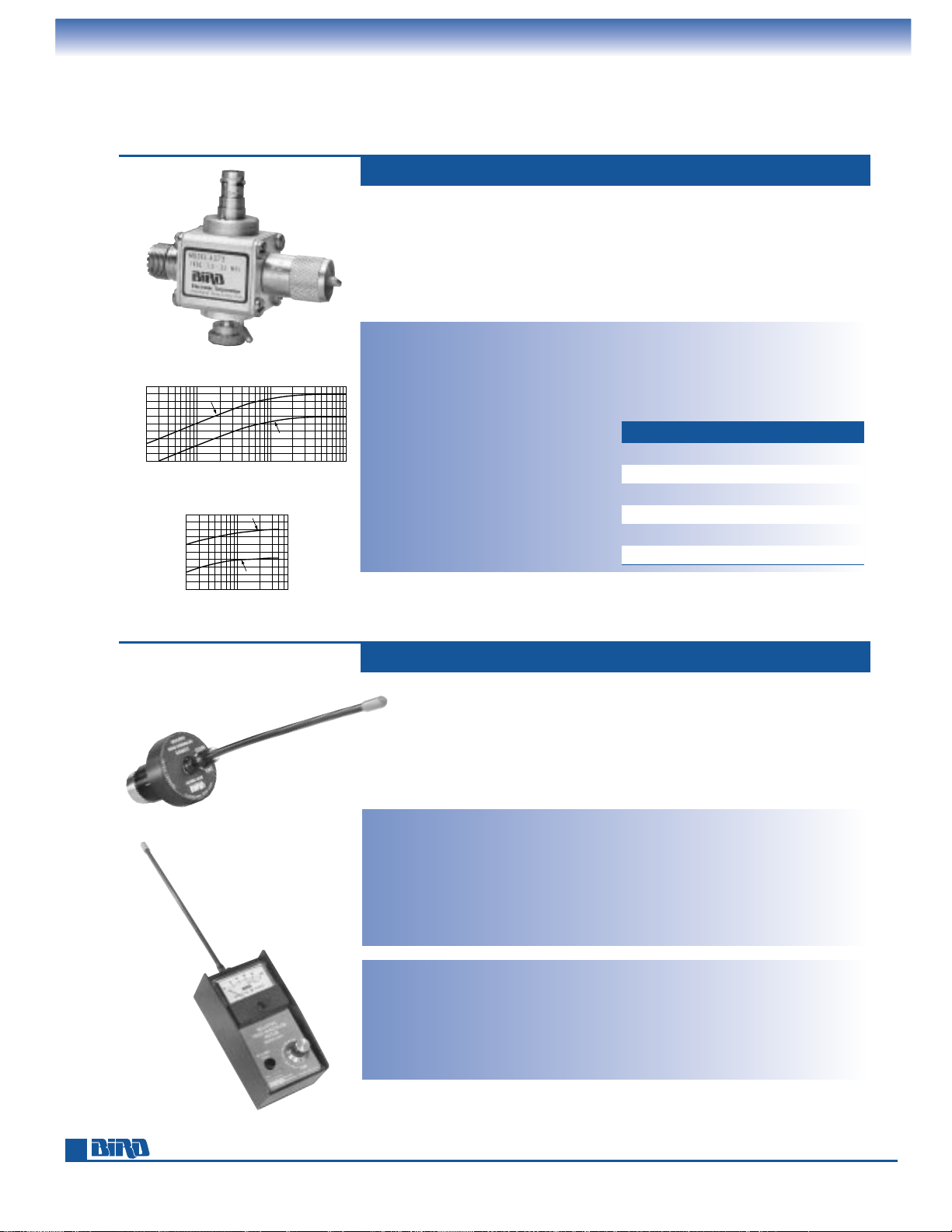
VARIABLE RF SIGNAL SAMPLERS,
FIELD-STRENGTH METERS
The Model 4273 (1.5 to 35 MHz, 5 kW max.) and Model 4275 (20 to 1000 MHz,
1 kW max.) are “stand-alone,” wide-range THRULINE
®
RF coupling probes for spectrum analysis, RF signal observation on a scope, or frequency counting and control.
They feature very low VSWR throughout a broad frequency and attenuation range.
Insertion loss is a negligible 0.1 dB. Both Models produce an unrectified sample
at the BNC port that is adjustable. Once adjusted, the setting can be locked in
place. The main power line connectors are Bird QC type.
Power Ratings: Model 4273: 5 kW max;
Model 4275; 1 kW max.
Frequency Range: Model 4273: 1.5 – 35 MHz;
Model 4275: 20 – 1000 MHz
Impedance: 50 ohms nominal
Insertion VSWR: with N connectors
Model 4273: 1.07 max. Model 4275:
1.1 max. 2 to 512 MHz, 1.25 max.
512 to 1000 MHz.
Insertion Loss: Model 4273: 0.1 dB max.
Model 4275: 0.1 dB max. 2 to 512 MHz,
0.2 dB max. 512 to 1000 MHz.
Coupling: Adjustable as shown within ±3 dB
Ambient Temperature Range: –40˚C to +45˚C
Connectors: QC type as specified
(no connectors required for 4275-100,
which is a sampler accessory for Bird
RF SIGNAL SAMPLERS MODELS 4273, 4275
instruments already equipped with
QC connectors)
Finish: Bright silver plate
Nominal Size: 251⁄64" L × 27⁄8" W × 11⁄4" D,
(71 mm
× 73 mm × 32 mm)
Weight: 10 oz. (280 g)
The modestly priced Model 4030 Relative Field-Strength Element expands the
capabilities of the Model 43 and other Bird THRULINE
®
wattmeters with 30 µA
meters by helping you optimize the radiated signal of any transmitter from
2–1000 MHz. It automatically turns on when plugged into the element socket and
features a gain control to adjust sensitivity to various field intensities. The Model
4041 Meter is a self-contained, compact instrument that performs exactly the same
functions as the 4030 Element.
FIELD-STRENGTH ELEMENT AND METER MODELS 4030, 4041
*Choose any two connectors from page 60.
**Accessory sampler for a Bird Instrument. Remove the instrument’s QC connector, place on sampler
and bolt both with the instrument.
Model: 4030
Frequency Range: 1 to 1000 MHz
Dynamic Range: 30 dB min.
Typical Sensitivity: Full scale deflection at
8 ft. (2
1
⁄2m) from a 1 W source broadcasting at 150 MHz through a quarter
wave antenna
Output Characteristics: Compatible with
30 µA meter instruments
(Models 43, 43P, 4305A, 4314B, 4410, 4430,
4431, 4521, 4522, 4526, 4527)
Battery Life: 100 hours min.
Battery Type: Three, 3V Lithium-Manganese
Dioxide, cells (Duracell DL2032 or
equivalent)
Ambient Temp Range: 0˚C to +50˚C
Weight: (includes batteries) 3 oz.
Model: 4041
Frequency Range: 1 to 1000 MHz
Dynamic Range: 30 dB min.
Typical Sensitivity: Full-scale deflection at
8 ft. (2
1
⁄2m) from a 1 W source broadcasting at 150 MHz through a quarter
wave antenna
Battery Life: 200 hours min.
Battery Type: One, 9V alkaline, “Transistor”
battery (NEDA No. 1604A)
Ambient Temp Range: 0˚C to +50˚C
Finish: Black anodized
Nominal Size: (w/o antenna) 43⁄8" L × 21⁄4" W
× 115⁄16" D, (111mm × 57mm × 49mm)
Weight: (includes batteries) 10 oz. (283 g)
MODEL/PART NO: QC – CONNECTORS:
4273-020 4275-020 N: Male/Female
4273-025 4275-025 N: Female/Female
4273-030 4275-030 UHF: Male/Female
4273-035 4275-035 UHF: Female/Female
4273 4275 None*
4273-100 4275-100 None Required**
MODEL 4030 ELEMENT
MODEL 4041 METER
MODEL 4273-030
MODEL 4275
MODEL 4273
Page 23
E-mail: [email protected] • Internet: www.bird-electronic.com
23
THRULINE
®
WATTMETER COMPONENTS
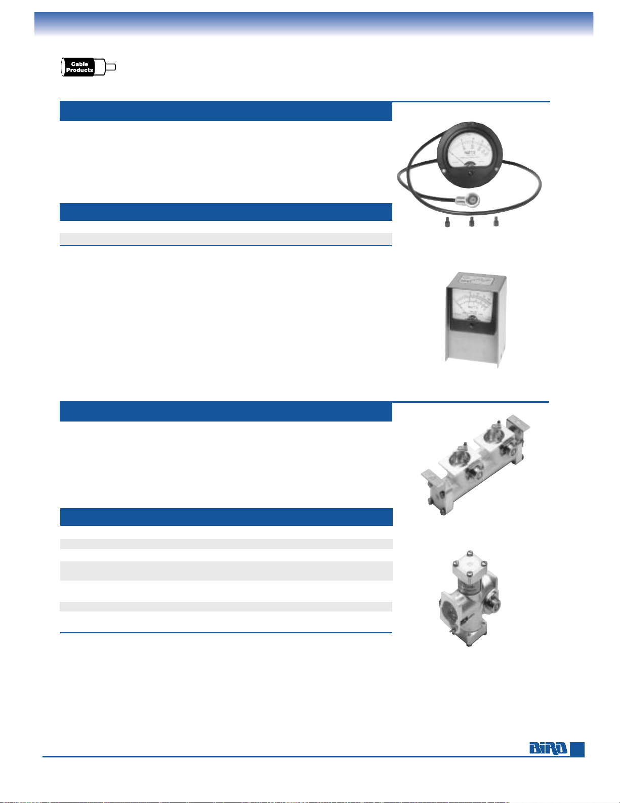
Meter Movement and Line Sections for 50-Ohm Cable Wattmeters
The Model 8-000 and Model 4210A100 meters, when combined with appropriate
7
⁄8" line section, QC connectors, and elements, enable you to assemble custom rack-
mount or benchtop wattmeters. The Model 8-000 is the same 3
1
⁄2"-diameter unit
used in our Model 43. The 4210A100 is 3
1
⁄4" square meter premounted in
an aluminum case. Both feature 30 µA/1400 Ω movements and include a cable
with DC connector. Both are used with elements from Tables 1, 2, 3, 3A, 4, 6 and14.
METER MOVEMENT 30 µA
Pages 25–28 present the full range of Plug-in Elements.
MODEL TYPE CURRENT SCALES USE WITH ELEMENT TABLES
8-000 31⁄2" Round Kit w/ Cable 30 µA/1400 Ω 25/50/100W 1, 2, 3, 3A, 4, 6, and 14
4210A100 3
1
⁄4" Square Meter in Housing 30 µA/1400 Ω 25/50/100W 1, 2, 3, 3A, 4, 6, and 14
LINE CONNECTOR ELEMENT LENGTH WEIGHT USE WITH
MODEL
TYPE* TYPE SOCKETS (INCHES) (LBS.) WATTMETERS
4230-018 Cable QC-N(F) 1 51⁄2 11⁄3 —
4230-006-1 Cable QC(not incld.) 1 4 1 —
4230-059 Cable QC(not incld.) 1 w/bracket 4 1
1
⁄4 —
4230-053 Cable QC(not incld.) 2 4 1 3128A, 4201A501, 4201A502,
4210A100, 8-000
4522-002-5 Cable QC(not incld.) 2 panel mt. 6
7
⁄32 11⁄4 3128A, 4201A501, 4201A502,
4210A100, 8-000
4501-000
7
⁄8" Flg. 1 4 1 —
4502-000
7
⁄8" Flg. 2 4 11⁄4 3128A, 4201A501, 4201A502,
4210A100, 8-000
Line sections to use with 50-ohm cable and 7⁄8" rigid line are listed below. Page 34
contains 1
5
⁄8", 31⁄8", 41⁄16", and 61⁄8" line sections.
Elements for the line sections below are found in Tables 1, 2, 3, 3A, 4, 6, and 14
on pages 25–28. Table 5 on page 27 can also be used with these products.
See page 60 for QC-Type connectors.
LINE SECTIONS CABLE, 7⁄8" RIGID LINE
* Cable = Use with cable connectors.
7
⁄8” = Use with 7⁄8" rigid line.
MODEL 4522-002-5
MODEL 8-000
MODEL 4210A100
MODEL 4230-053
Page 24
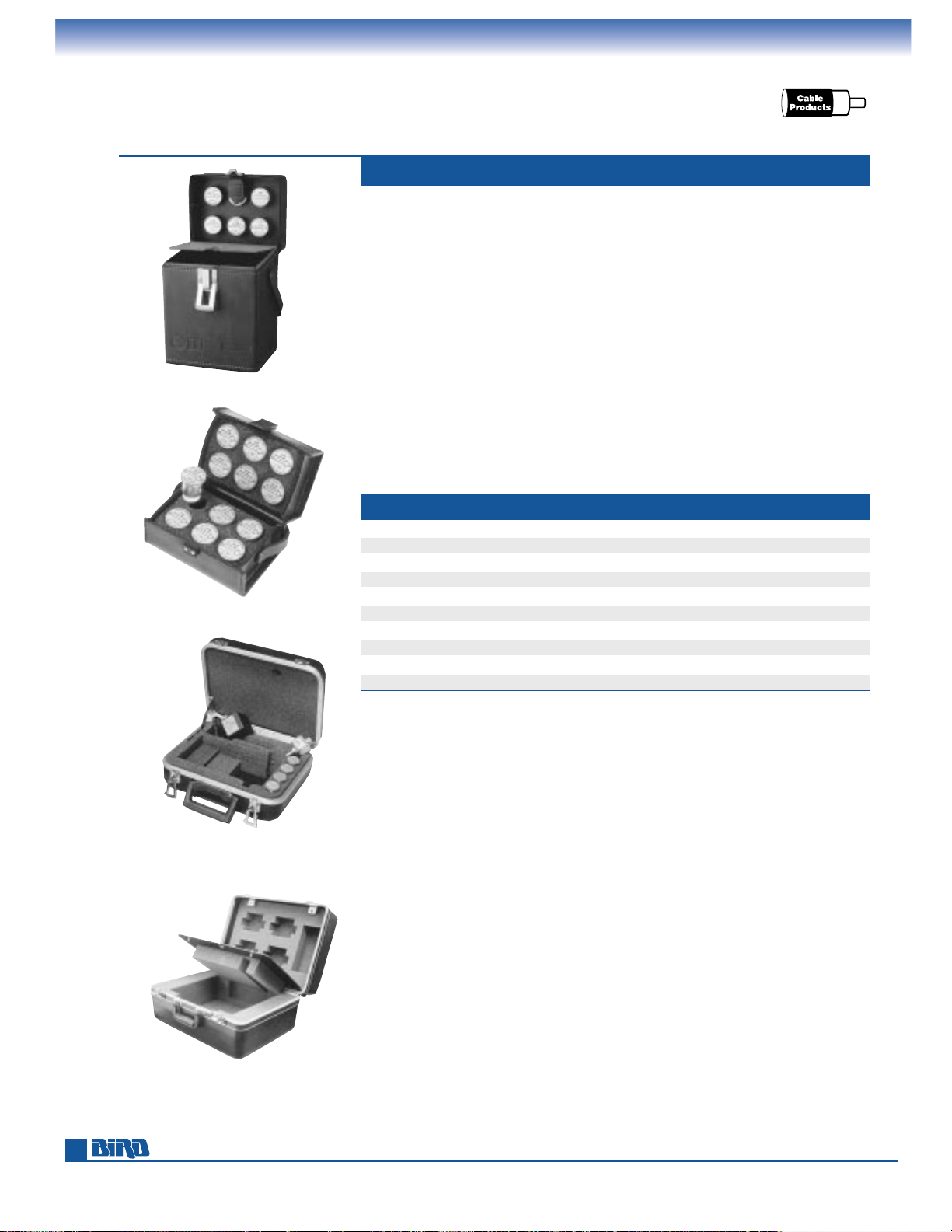
Phone: 440-248-1200 • Fax: 440-248-5426
24
WATTMETER
AND ACCESSORY CASES
See our other wattmeter accessories: Attenuators (pages. 54–58), Batteries (page 61),
Connector Adapters and Kits (page 61), Loads (pages. 42–53), Signal Samplers (page 22),
and QC and SQC Connectors (pages. 60).
We offer a complete selection of sturdy cases specially designed to protect your
THRULINE
®
Wattmeter and organize elements and accessories.
CC Series cases are crafted from top-grade expanded vinyl that looks and feels
like brown leather, but requires none of the care. Brass-plated hardware and an
embossed Bird seal add to the handsome appearance. The interiors of the Models
CC-1 and CC-3 feature velcro closures and cutouts to secure accessories plus a
43-size wattmeter.
The Model EC-1 element case lets you organize up to 12 Plug-In elements in a
die-cut foam insert. The exterior is crafted from high-density expanded vinyl, with
a tanned brown finish and gold-tone hardware.
Hard-sided 4300 Series cases include shock-absorbing laminated die-cut foam inserts.
These cases feature fold down handles, quick-release latches, rigid aluminum frame
and durable polyurethane shell.
CASES CC, EC, 4300 SERIES
MODEL CASE HOLDS
CC-1 Portable THRULINE®Wattmeter* and 6 elements
CC-2 Mini-Monitor
CC-3 Portable THRULINE
®
Wattmeter*, load, and 3 elements
EC-1 12 elements
4300-061 Model 43 or 43P Wattmeter, load, signal sampler, QC connectors, and 4 elements
4300-070 Portable THRULINE
®
Wattmeter*, test cable, screw driver, QC connectors, and 15 elements
4300-085 4391 POWER ANALYST
®
, signal sampler, and 4 elements
4300-055 4410 Wattmeter, load, elements, and other accessories
4300A215 4421 Wattmeter and power sensors
7000A850 AT-100, AT-400, AT-800 Antenna Testers
* Includes THRULINE®Wattmeter Models: APM-16, 43, 43P, 4304A, 4308, 4314B, 4410A, 4430 and 4431.
MODEL CC-1
MODEL EC-1
MODEL 4300-085
MODEL 4300A215
Page 25
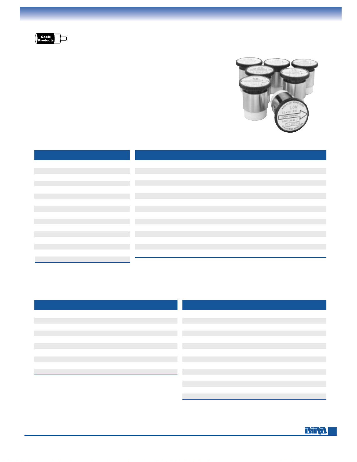
E-mail: [email protected] • Internet: www.bird-electronic.com
25
PLUG-IN ELEMENTS
Selection Guides, Standard and Low Power
All Bird Plug-In Elements are manufactured in accordance with meticulous calibration
procedures, supported by more than a quarter-century history of mean deviation
values. This assures adherence to advertised specifications of our current instruments
as well as field interchangeability with Bird equipment you might have purchased
many years ago. Stated instrument accuracies cannot be guaranteed with components
not supplied by Bird.
Pages 25–28 contain the most popular elements for wattmeters used with 50-ohm
cable (elements for rigid line use are on pages 36–38). While our large selection
lets you almost customize your Bird wattmeter, one or two elements are sufficient
for most applications. Always specify your wattmeter or line section number when
ordering elements.
Unless noted otherwise, element tables listed below are found on pages 25–28.
WATTMETER SELECT ELEMENT
MODEL FROM TABLE(S)
APM-16 APM Table
3128A 1, 2, 3, 3A, 4, 6, 14*
3170A 1, 2, 3, 3A, 4, 6, 14*
43 1, 2, 3, 3A, 4, 6, 14*
43P 1, 2, 3, 3A, 4, 5, 6
4304A
—
4305A 8, 1
5
⁄8AA**
4308 —
4314B 1, 2, 3, 3A, 4, 5, 6, 14*
4391A 1, 2, 3, 3A, 4, 5, 6, 14*
4410A, 4412 9, 10, 11, 12, 14*
4431 1, 2, 3, 3A, 4, 6, 14*
4521, 4522 1, 2, 3, 3A, 4, 6, 14*
4526 1, 2, 3, 3A, 4, 6, 14*
4527 1, 2, 6, 14*
6151 1, 2, 3
ELEMENT MIN PWR MAX PWR. MIN FREQ MAX FREQ SEE
TABLE (WATTS F.S.) (WATTS F.S.) (MHz) (MHz) PAGE
APM 1 1000 2 2300 28
1 5 5000 2 1000 25
2 1 2.5 25 1000 25
3 1 250 950 2700 26
3A 0.1 0.5 950 2600 26
4 1000 10,000 0.45 2.5 26
5 500 10,000 2 1260 27
6 0.1 0.5 45 1000 26
8 50 25,000 0.45 2300 27
9 0.01 10 30 1000 27
9A 0.001 1 864 970 27
10 0.1 100 25 2300 27
11 1 1000 2 1000 27
12 10 10,000 0.2 30 27
14 1000 1000 50 1250 28
ELEMENT SELECTION GUIDE
* Table 14 describes coupler elements used for RF sampling.
The instrument meter does not read when these elements are
installed, but simply serves as a line section.
** See page 37 for Table 1-5/8AA
ELEMENT TABLE FREQUENCY AND POWER LIMITS
FREQUENCY BANDS (MHz)
POWER RANGE
2-30 25-60 50-125 100-250 200-500 400-1000
5 W — 5A 5B 5C 5D 5E
10 W — 10A 10B 10C 10D 10E
25 W — 25A 25B 25C 25D 25E
50 W 50H 50A 50B 50C 50D 50E
100 W 100H 100A 100B 100C 100D 100E
250 W 250H 250A 250B 250C 250D 250E
500 W 500H 500A 500B 500C 500D 500E
1000 W 1000H 1000A 1000B 1000C 1000D 1000E
2500 W 2500H — — — — —
5000 W 5000H — — — — —
TABLE 1 STANDARD ELEMENTS
1.0 WATT MODEL 2.5 WATTS MODEL
25–30 MHz 025-1 25–30 MHz 025-2
30–35 MHz 030-1 30–40 MHz 030-2
35–40 MHz 035-1 40–50 MHz 040-2
40–50 MHz 040-1 50–60 MHz 050-2
50–60 MHz 050-1 60–80 MHz 060-2
60–80 MHz 060-1 80–95 MHz 080-2
80–95 MHz 080-1 95–150 MHz 095-2
95–125 MHz 095-1 150–250 MHz 150-2
110–160 MHz 110-1 200–300 MHz 200-2
150–250 MHz 150-1 250–450 MHz 250-2
200–300 MHz 200-1 400–850 MHz 400-2
275–450 MHz 275-1 800–1000 MHz 801-2
425–850 MHz 425-1
— —
800–1000 MHz 801-1 — —
TABLE 2 LOW-POWER ELEMENTS
Elements for wattmeters used with rigid lines are found
on pages 36
–
38.
Page 26
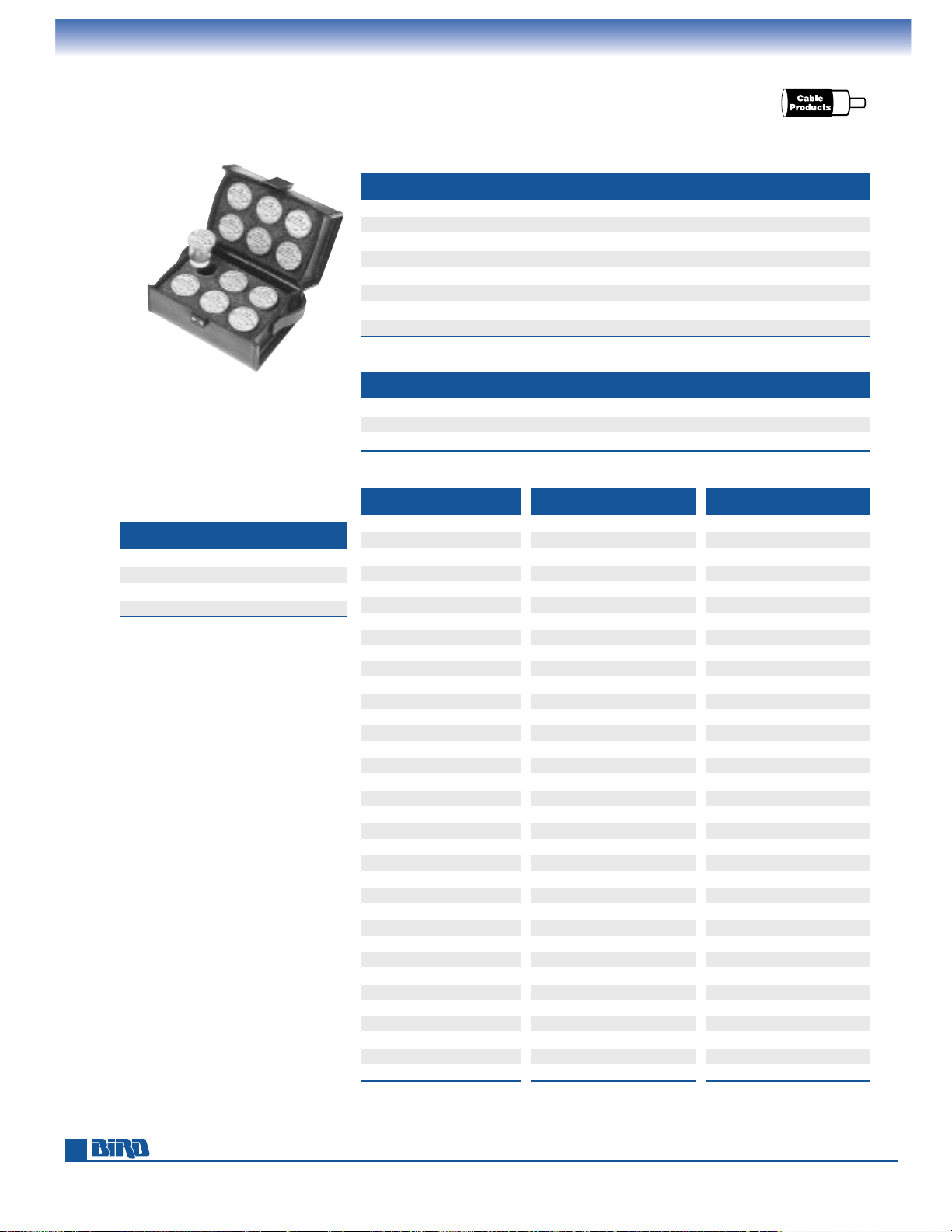
Phone: 440-248-1200 • Fax: 440-248-5426
26
PLUG-IN ELEMENTS
High Frequency, Low Frequency and Milliwatt
Protect and organize your
elements with a case.
See page 24.
POWER FREQUENCY BANDS (MHz)
RANGE 950-1260 1100-1800 1700-2200 2200-2300 2300-2400 2400-2500 2500-2600 2600-2700
1 W 1J 1K 1L 1M 431-17 431-20 431-23 431-120
2.5 W 2.5J 2.5K 2.5L 2.5M 431-110 431-107 431-108 431-117
5 W 5J 5K 5L 5M 432-15 432-28 432-2 432-12
10 W 10J 10K 10L 10M 432-125 432-141 432-102 432-104
25 W 25J 25K 25L 25M 433-19 433-20 433-35 433-36
50 W 50J 50K 50L 50M 433-37 433-38 433-163 433-164
100 W 100J — — — — — — —
250 W 250J — — — — — — —
TABLE 3 HIGH-FREQUENCY ELEMENTS. ENTIRE TABLE ±8% FS
POWER FREQUENCY BANDS (MHz)
RANGE 950-1260 1250-1500 1500-1700 1700-2200 2200-2300 2300-2400 2400-2500 2500-2600
100 mW 430-82 430-209 430-210 430-178 430-41 430-211 430-182 430-90
250 mW 430-83 430-236 430-237 430-1 430-238 430-239 430-240 430-241
500 mW 430-84 430-259 430-260 430-95 430-78 430-261 430-159 430-262
TABLE 3A HIGH-FREQUENCY MILLIWATT ELEMENTS
100 mW MODEL 250 mW MODEL 500 mW MODEL
45–50 MHz 430-266 45–50 MHz 430-267 45–54 MHz 430-242
50–60 MHz 430-191 50–60 MHz 430-212 54–60 MHz 430-243
60–66 MHz 430-192 60–66 MHz 430-213 60–66 MHz 430-244
66–72 MHz 430-193 66–72 MHz 430-214 66–72 MHz 430-245
72–76 MHz 430-2 72–76 MHz 430-22 72–76 MHz 430-33
76–82 MHz 430-194 76–82 MHz 430-215 76–88 MHz 430-246
82–88 MHz 430-195 82–88 MHz 430-216 88–108 MHz 430-247
88–97 MHz 430-170 88–108 MHz 430-217 105–120 MHz 430-26
97–108 MHz 430-171 105–120 MHz 430-20 120–136 MHz 430-248
108–136 MHz 430-57 116–126 MHz 430-48 136–150 MHz 430-249
135–175 MHz 430-86 125–136 MHz 430-218 150–170 MHz 430-53
170–190 MHz 430-62 130–150 MHz 430-13 170–190 MHz 430-250
190–210 MHz 430-63 150–180 MHz 430-15 190–216 MHz 430-251
210–216 MHz 430-176 170–190 MHz 430-64 216–240 MHz 430-252
216–230 MHz 430-196 190–210 MHz 430-65 240–290 MHz 430-27
230–240 MHz 430-197 210–220 MHz 430-184 290–340 MHz 430-253
240–250 MHz 430-198 216–230 MHz 430-219 340–360 MHz 430-157
250–260 MHz 430-199 230–240 MHz 430-220 350–400 MHz 430-254
260–270 MHz 430-200 240–250 MHz 430-221 400–450 MHz 430-255
270–280 MHz 430-201 250–260 MHz 430-222 450–500 MHz 430-256
280–290 MHz 430-202 260–270 MHz 430-223 500–600 MHz 430-257
290–300 MHz 430-203 270–280 MHz 430-224 600–800 MHz 430-258
300–320 MHz 430-204 280–290 MHz 430-225 800–1000 MHz 430-265
320–340 MHz 430-205 290–300 MHz 430-226 — —
340–360 MHz 430-164 300–320 MHz 430-227 — —
360–380 MHz 430-206 320-–340 MHz 430-228 — —
380–400 Mhz 430-207 340–360 MHz 430-229 — —
400–420 MHz 430-7 360–380 MHz 430-230 — —
420–450 MHz 430-208 375–400 MHz 430-231 — —
450–470 MHz 430-8 400–450 MHz 430-232 — —
470–500 MHz 430-179 450–470 MHz 430-61 — —
500–600 MHz 430-168 470–500 MHz 430-233 — —
600–800 MHz 430-169 500–600 MHz 430-234 — —
800–1000 MHz 430-263 600–800 MHz 430-235 — —
— — 800–1000 MHz 430-264 — —
FREQUENCY BANDS (MHz)
POWER RANGE 0.45 TO 2.5
1000 W 1000P
2500 W 2500P
5000 W 5000P
10,000 W 10000P
TABLE 4 LOW-FREQUENCY
ELEMENTS
TABLE 6 MILLIWATT ELEMENTS
Elements for wattmeters used with rigid lines are found on pages 36–38.
Page 27
E-mail: [email protected] • Internet: www.bird-electronic.com
27
Table 5 Notes:
Elements 500–10,000 watts, 950–1260 MHz,
are rated at 100 watts avg.
Elements 2500 watts and higher, 25
–1000 MHz,
are rated at 1000 watts avg.
Elements 2500A, 2500B, 2500C, 5000A, and
10000H are capable of reading peak and
average power.
PLUG-IN ELEMENTS
Pulse Power, 4410 Series
FREQUENCY (MHz) POWER MODEL
.45–2.5 25 kW 25KP7
2–30 10 kW 10KH7
25–60 2500 W 2500A7
25–60 5000 W 5000A7
50–125 2500 W 2500B7
50–125 5000 W 5000B7
100–250 2500 W 2500C7
200–500 2500 W 2500D7
400–1000 2500 W 2500 E7
1100–1800 50 W 50K7
1100–1800 100 W 100K7
1700–2200 50 W 50L7
1700–2200 100 W 100L7
2200–2300 50 W 50M7
2200–2300 100 W 100M7
TABLE 8 PLUG-IN ELEMENTS FOR MODEL 4305A*
*4305A may also use elements from Table 15⁄8AA on page 37.
FULL-SCALE POWER AND FREQUENCY RANGES
0–10, 30, 100, 300 MILLIWATTS
1, 3, 10 WATTS
MHz MODEL
30–50 4410-20
50–88 4410-21
88–108 4410-27
100–152 4410-22
150–250 4410-23
225–400 4410-24
400–800 4410-25
800–900 4410-26
900–1000 4410-28
TABLE 9 4410 ELEMENTS
FULL-SCALE POWER AND FREQUENCY RANGES
0–1, 3, 10, 30, 100, 300, 1000 WATTS
MHz MODEL
2–30 4410-3
25–80 4410-5
50–200 4410-6
144–520 4410-7
200–1000 4410-8
TABLE 11 4410 ELEMENTS
FULL-SCALE POWER AND FREQUENCY RANGES
0–10, 30, 100, 300, 1000, 3000, 10,000 WATTS
MHz MODEL
0.2–0.535 4410-1
0.45–2.5 4410-2
2–30 4410-4
TABLE 12 4410 ELEMENTS
FULL-SCALE POWER AND FREQUENCY RANGES
0–1, 3, 10, 30, 100, 300 MILLIWATTS AND 1 WATT
MHz MODEL ACCURACY
864–868 4410-38
±
10% of reading accuracy
on 100 mW, 300 mW and
1 W, ±5% on all other scales
917–970 4410-29
±
5% 10 mW to 1 W only
TABLE 9A 4410 ELEMENTS
FULL-SCALE POWER AND FREQUENCY RANGES
0–100, 300 MILLIWATTS
1, 3, 10, 30, 100 WATTS
MHz MODEL
25–80 4410-10
50–125 4410-11
100–250 4410-12
200–500 4410-13
400–1000 4410-14
1000–1800 4410-15*
1800–2300 4410-16*
TABLE 10 4410 ELEMENTS
*Accuracy is ±8% of reading
Elements for wattmeters used with rigid lines are found on pages 36–38.
POWER FREQUENCY BANDS (MHz)
RANGE 2-30 25-60 50-125 100-250 200-500 400-1000 950-1260
500 W — — — — — — 500J
1000 W — — — — — — 1000J
2500 W — 2500A 2500B 2500C 2500D 2500E 2500J
5000 W — 5000A 5000B 5000C 5000D 5000E 5000J
10000 W 10000H 10000A 10000B 10000C 10000D 10000E 10000J
TABLE 5 PULSE-POWER ELEMENTS
ENTIRE TABLE ±8% OF FULL SCALE
Page 28
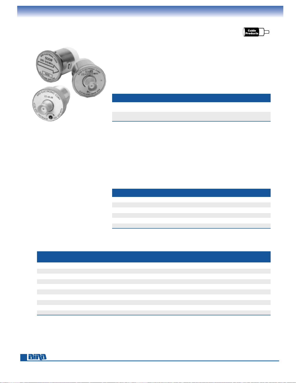
Phone: 440-248-1200 • Fax: 440-248-5426
28
The 4274 Series sampler elements are nondirectional couplers that replace the standard element in your Bird wattmeter for such applications as RF signal observation,
spectrum analysis or frequency counting and control where main line power does not
exceed 500 W. The Model 4274-025 is a wide-range device that provides an unrectified
signal at about
–
50 dB ±2 dB from 25–1000 MHz tapering to –66 dB at 2 MHz. The
Model 4274-050 delivers a variable unrectified signal from
–
35 to –48 dB (±1 dB) from
100–400 MHz.
The directional coupler plug-in elements in Table 14 below are used for signal leveling,
frequency control, wave-shape monitoring, local oscillator or marker-signal injection,
etc. They extract a calibrated amount of power from the main line signal flowing in
the direction of the arrow. This attenuated signal is NOT rectified (as in the standard
measuring elements), but is brought out through a female BNC connector on top of the
element. Coupler elements fit the standard sockets, but there are no DC output tabs
on the element body since no DC is produced. An added convenience is rotating the
element between 0˚ and 180˚ varies the amount of coupling like a variable attenuator.
Minimum attenuation of the main line signal is the nominal coupling±1 dB shown
for each unit within the stated frequency band.
Variable 4274-050
(lower left) and wide-range
4274-025 (upper right)
sampler elements shown
with a standard element.
FREQUENCY NOMINAL MAX. MAIN
BAND (MHz) COUPLING LINE POWER*
MODEL
50–100 –40 dB 1 kW 400-50
75–150 –40 dB 1 kW 400-75
125–250 –40 dB 1 kW 400-125
225–450 –40 dB 1 kW 400-225
400–800 –40 dB 1 kW 400-400
750–1250 –40 dB 1 kW 400-750
TABLE 14 DIRECTIONAL COUPLER ELEMENTS FOR QC-TYPE OR 7⁄8" EIA LINE
*The power rating of the directional couplers cannot exceed the peak and average power ratings of the
transmission line.
FREQUENCY NOMINAL MAX. MAIN
BAND (MHz) COUPLING LINE POWER*
MODEL
25–1000 –50 dB ± 2 dB 500 W 4274-025
(–66 dB @ 2 MHz)
100–400 –35 to –48 dB (± 1 dB) 500 W 4274-050
Adjustable
NONDIRECTIONAL SAMPLER ELEMENTS FOR QC-TYPE OR 7⁄8" EIA LINE
FREQUENCY BANDS (MHz)
POWER
2- 25- 50- 100- 200- 400- 950- 1100- 1700- 2200-
RANGE
30 60 125 250 500 1000 1260 1800 2200 2300
1W — APM-1A APM-1B APM-1C APM-1D APM-1E APM-1J APM-1K APM-1L APM-1M
2.5W — APM-2.5A APM-2.5B APM-2.5C APM-2.5D APM-2.5E APM-2.5J APM-2.5K APM-2.5L APM-2.5M
5 W APM-5H APM-5A APM-5B APM-5C APM-5D APM-5E APM-5J APM-5K APM-5L APM-5M
10 W APM-10H APM-10A APM-10B APM-10C APM-10D APM-10E APM-10J APM-10K APM-10L APM-10M
25 W APM-25H APM-25A APM-25B APM-25C APM-25D APM-25E APM-25J APM-25K APM-25L APM-25M
50 W APM-50H APM-50A APM-50B APM-50C APM-50D APM-50E APM-50J APM-50K APM-50L —
100 W APM-100H APM-100A APM-100B APM-100C APM-100D APM-100E APM-100J — — —
250 W APM-250H APM-250A APM-250B APM-250C APM-250D APM-250E APM-250J — — —
500 W APM-500H APM-500A APM-500B APM-500C APM-500D APM-500E — — — —
1000 W APM-1000H APM-1000A APM-1000B APM-1000C APM-1000D APM-1000E — — — —
APM ELEMENTS FOR APM-16
PLUG-IN ELEMENTS
Sampler, Coupler, and APM
Page 29
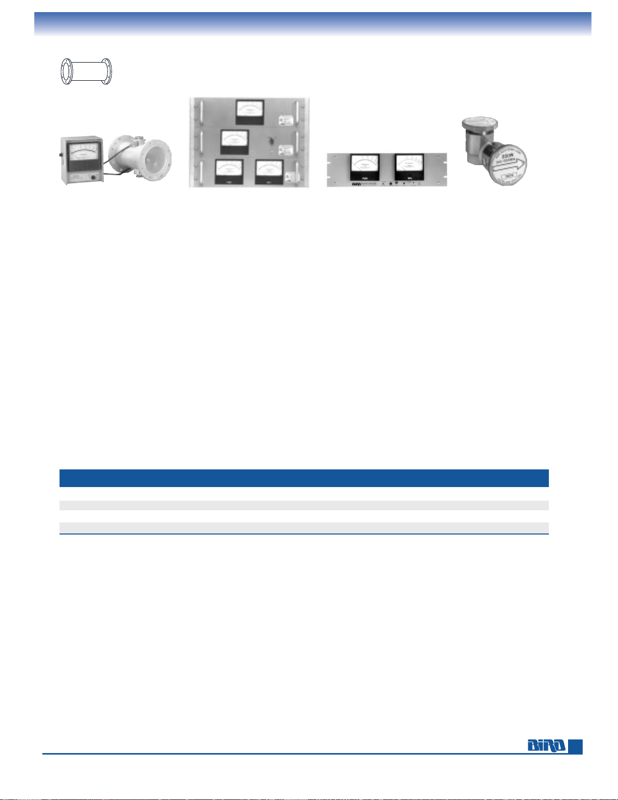
E-mail: [email protected] • Internet: www.bird-electronic.com
29
RF POWER METER
SELECTION GUIDE
Power Meters For Rigid Line Use
Bird High-Power Wattmeters measure forward and reflected power in 15⁄8" through 61⁄8" rigid line systems up to
250kW. The 4600A, 4700A, 4800A, and 4900A Series are prepackaged, semiportable systems consisting of a line section and
meter with attached 10-foot cabling. Selected packages include a dual-element line section and switchable meter unit, permitting convenient forward or reflected power readings at the flip of a switch. For maximum flexibility, you can also assemble a custom system from a 6810-Series portable meter or 3127-Series panel-mount meter (page 35) and an appropriate line
section (page 34).
Wattmeter packages, as well as the 3127 and 6810 Series meters, contain 100 µA movements designed for use with Bird
Plug-in Elements from the ”A“, ”B“, or ”C“ tables (pages 37–38). Order elements according to your line section size,
the required power and frequency, and meter scales.
The WATTCHER
®
Models on pages 32–33 are designed to protect your equipment from damage caused by high VSWR or
abnormal load conditions. These instruments provide visual and audible alarms as well as switching capabilities to shut
down a transmitter, turn on deicing equipment, etc.
The table below will help direct you to a Bird 1
5
⁄8", 31⁄8", 41⁄16", or 61⁄8" High-Power Wattmeter package to fit
your needs. Turn to the referenced page for full product descriptions and specifications. You can also contact Bird or any
authorized distributor for further assistance.
If your applications include
7
⁄8" coaxial systems, please see the wattmeter selection guide on page 9.
This catalog contains RF Terminations that will terminate up to 80 kW. See pages 42–53.
HIGH-POWER
WATTMETERS
Pages 30–31
LINE SECTIONS Page 34
PANEL-MOUNT
METERS
Page 35
WATTCHER®RF
MONITORING
SYSTEMS
Pages 32–33
ELEMENTS
Pages 36–38
LINE SIZE POWER
FREQ. FULL-SCALE DISPLAY SEE
(MHz) ACCURACY TYPE PAGE
15⁄8" EIA 100W – 25kW 2–1000
±
5% FS Analog 30
3
1
⁄8" EIA 100W – 100kW 2–1000
±
5% FS Analog 30
4
1
⁄16" 1500W – 80kW 50–1000
±
5% FS Analog 31
6
1
⁄8" EIA 1000W – 250kW 2–1000
±
5% FS Analog 31
HIGH-POWER WATTMETER PACKAGES
Rigid LineRigid Line
PrProductsoducts
Page 30
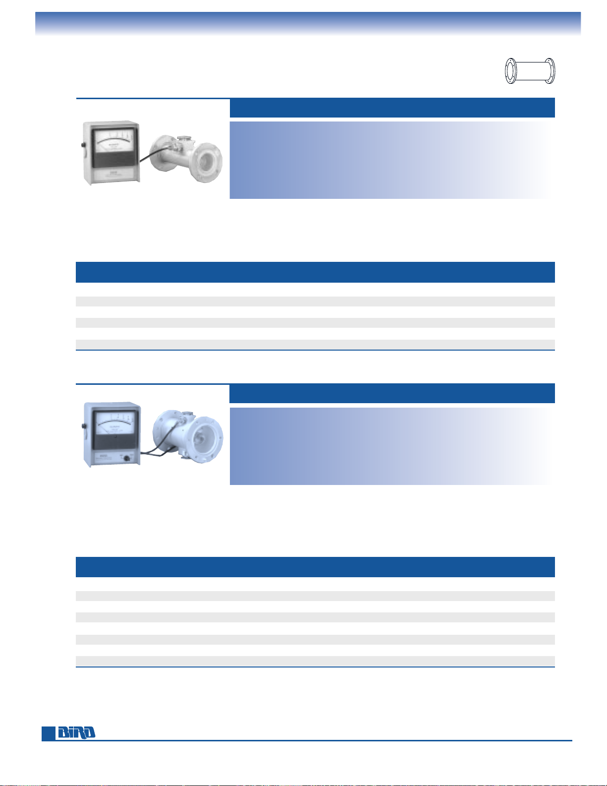
Phone: 440-248-1200 • Fax: 440-248-5426
30
MODEL 4712A shown.
All models on pages 30–31
include meter and line section.
THRULINE
®
RF DIRECTIONAL WATTMETERS
15⁄8" and 31⁄8" WATTMETER PACKAGES
15⁄8" WATTMETER PACKAGES - 50 OHMS NOMINAL
Insertion VSWR: 1.05 max.
Accuracy:
±
5% of full scale
Cable/Connectors: Permanently attached
10 foot cable(s) with DC connector(s)
Finish:
Meter: Gray powder coat
Line Section: Bright silver plated
Nominal Size (Meter): 59⁄16" W ×61⁄2" H
×
33⁄8" D, (141 mm ×165 mm ×85 mm)
Weight (Meter): 3 lbs. (1.4 kg)
Insertion VSWR: 1.05 max.
Accuracy:
±
5% of full scale
Cable/Connectors: Permanently attached
10 foot cable(s) with DC connector(s)
Finish:
Meter: Gray powder coat
Line Section: Bright silver plated
Nominal Size (Meter): 59⁄16" W ×61⁄2" H
×
33⁄8" D, (141 mm ×165 mm ×85 mm)
Weight (Meter): 3 lbs. (1.4 kg)
31⁄8" WATTMETER PACKAGES - 50 OHMS NOMINAL
MODEL 4610-200A
MODEL FREQ. RANGE POWER NUMBER SCALE ELEMENT LINE SECTION LINE SECTION
NO. (MHz) RANGE (kW)
FLG/UNFLG
SOCKETS DIVISIONS TABLE LENGTH WEIGHT
4712A 2–1000 0.1–25 EIA Flg. Single 5/10/25 15⁄8A 63⁄4" (171 mm) 3 lbs. (1.4 kg)
4715-200A 2–1000 0.1–25 EIA Flg. Double 5/10/25 1
5
⁄8A 63⁄4" (171 mm) 31⁄4 lbs. (1.48 kg)
4720A 2–1000 0.1–25 Unflg. (Rec. 0.438") Single 5/10/25 1
5
⁄8A 63⁄8" (162 mm) 11⁄4 lbs. (0.6 kg)
4723-200A 2–1000 0.1–25 Unflg. (Rec. 0.438") Double 5/10/25 1
5
⁄8A 63⁄8" (162 mm) 11⁄2 lbs.(0.7 kg)
4712-037A 2–1000 0.3–15 EIA Flg. Single 15/30/60 1
5
⁄8A 63⁄4" (171 mm) 3 lbs. (1.4 kg)
4715-300A 2–1000 0.3–15 EIA Flg. Double 15/30/60 1
5
⁄8A 63⁄4" (171 mm) 31⁄4 lbs. (1.48 kg)
MODEL FREQ. RANGE POWER NUMBER SCALE ELEMENT LINE SECTION LINE SECTION
NO. (MHz) RANGE (kW)
FLG/UNFLG
SOCKETS DIVISIONS TABLE LENGTH WEIGHT
460A 2–1000 0.1–100 EIA Flg. Single 5/10/25 31⁄8A 71⁄32" (179 mm) 7 lbs. (3.2 kg)
4610-200A 2–1000 0.1–100 EIA Flg. Double 5/10/25 3
1
⁄8A 71⁄32" (179 mm) 71⁄4 lbs. (3.3 kg)
4805A 2–1000 0.1–100 Unflg. (Flush) Single 5/10/25 3
1
⁄8A 61⁄2" (165 mm) 4 lbs. (1.82 kg)
4802-200A 2–1000 0.1–100 Unflg. (Flush) Double 5/10/25 3
1
⁄8A 61⁄2" (165 mm) 41⁄4 lbs. (1.94 kg)
4600-037A 50–1000 0.6–30 EIA Flg. Single 15/30/60 3
1
⁄8B 71⁄32" (179 mm) 7 lbs. (3.2 kg)
4610-300A 50–1000 0.6–30 EIA Flg. Double 15/30/60 3
1
⁄8B 71⁄32" (179 mm) 71⁄4 lbs. (3.3 kg)
4805-037A 50–1000 0.6–30 Unflg. (Flush) Single 15/30/60 3
1
⁄8B 61⁄2" (165 mm) 4 lbs. (1.82 kg)
4802-300A 50–1000 0.6–30 Unflg. (Flush) Double 15/30/60 3
1
⁄8B 61⁄2" (165 mm) 41⁄4 lbs. (1.94 kg)
Elements for rigid line wattmeter packages are found on pages 36–38.
Rigid LineRigid Line
PrProductsoducts
Page 31
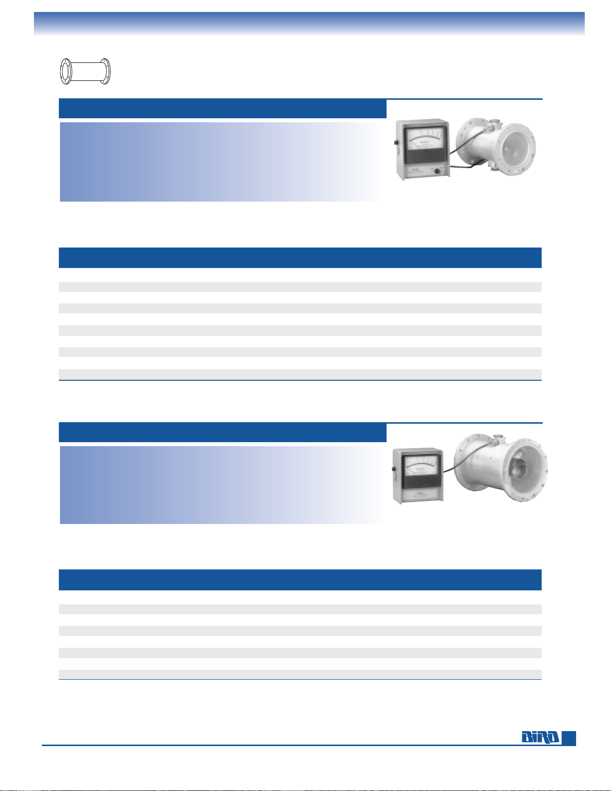
E-mail: [email protected] • Internet: www.bird-electronic.com
31
THRULINE
®
RF DIRECTIONAL WATTMETERS
41⁄16" and 61⁄8" WATTMETER PACKAGES
41⁄16" WATTMETER PACKAGES - 50 OHMS NOMINAL
MODEL 4902A
MODEL 4642-200A
Insertion VSWR: 1.05 max.
Accuracy:
±
5% of full scale
Cable/Connectors: Permanently attached
10 foot cable(s) with DC connector(s)
Finish:
Meter: Gray powder coat
Line Section: Bright silver plated
Nominal Size (Meter): 59⁄16" W × 61⁄2" H ×
33⁄8" D, (141 mm × 165 mm × 85 mm)
Weight (Meter): 3 lbs. (1.4 kg)
61⁄8" WATTMETER PACKAGES - 50 OHMS NOMINAL
Insertion VSWR: 1.05 max.
Accuracy:
±
5% of full scale
Cable/Connectors: Permanently attached
10 foot cable(s) with DC connector(s)
Finish:
Meter: Gray powder coat
Line Section: Bright silver plated
Nominal Size (Meter): 59⁄16" W × 61⁄2" H ×
33⁄8" D, (141 mm × 165 mm × 85 mm)
Weight (Meter): 3 lbs. (1.4 kg)
MODEL FREQ. RANGE POWER NUMBER SCALE ELEMENT LINE SECTION LINE SECTION
NO. (MHz) RANGE (kW)
FLG/UNFLG
SOCKETS DIVISIONS TABLE LENGTH WEIGHT
4641A 50–1000 2.5–50 EIA Flg. Single 5/10/25 41⁄16A 83⁄8" (213 mm) 85⁄8 lbs. (3.9 kg)
4642-200A 50–1000 2.5–50 EIA Flg. Double 5/10/25 4
1
⁄16A 83⁄8" (213 mm) 87⁄8 lbs. (4.0 kg)
4843A 50–1000 2.5–50 Unflg. (Rec. 0.531") Single 5/10/25 4
1
⁄16A 71⁄2" (191 mm) 25⁄8 lbs. (1.2 kg)
4844-200A 50–1000 2.5–50 Unflg. (Rec. 0.531") Double 5/10/25 4
1
⁄16A 71⁄2" (191 mm) 27⁄8 lbs. (1.3 kg)
4641-037A 50–1000 3–60 EIA Flg. Single 15/30/60 4
1
⁄16B 83⁄8" (213 mm) 85⁄8 lbs. (3.9 kg)
4642-300A 50–1000 3–60 EIA Flg. Double 15/30/60 4
1
⁄16B 83⁄8" (213 mm) 87⁄8 lbs. (4.0 kg)
4843-037A 50–1000 3–60 Unflg. (Rec. 0.531") Single 15/30/60 4
1
⁄16B 71⁄2" (191 mm) 25⁄8 lbs. (1.2 kg)
4844-300A 50–1000 3–60 Unflg. (Rec. 0.531") Double 15/30/60 4
1
⁄16B 71⁄2" (191 mm) 27⁄8 lbs. (1.3 kg)
4641-080A 50–1000 8–80 EIA Flg. Single 8/80 4
1
⁄16C 83⁄8" (213 mm) 85⁄8 lbs. (3.9 kg)
4843-080A 50–1000 8–80 Unflg. (Rec. 0.531") Single 8/80 4
1
⁄16C 71⁄2" (191 mm) 25⁄8 lbs. (1.2 kg)
MODEL FREQ. RANGE POWER NUMBER SCALE ELEMENT LINE SECTION LINE SECTION
NO. (MHz) RANGE (kW)
FLG/UNFLG
SOCKETS DIVISIONS TABLE LENGTH WEIGHT
4902A 2–1000 1–250 EIA Flg. Single 5/10/25 61⁄8A 107⁄32" (260 mm) 163⁄4 lbs. (7.6 kg)
4905-200A 2–1000 1–250 EIA Flg. Double 5/10/25 6
1
⁄8A 107⁄32" (260 mm) 17 lbs. (7.7 kg)
4907A 2–1000 1–250 Unflg. (Rec. 0.968") Single 5/10/25 6
1
⁄8A 95⁄8" (245 mm) 121⁄2 lbs. (5.7 kg)
4909-200A 2–1000 1–250 Unflg. (Rec. 0.968") Double 5/10/25 6
1
⁄8A 95⁄8" (245 mm) 123⁄4 lbs. (5.8kg)
4902-037A 50–1000 3–60 EIA Flg. Single 15/30/60 6
1
⁄8B 107⁄32" (260 mm) 163⁄4 lbs. (7.6 kg)
4905-300A 50–1000 3–60 EIA Flg. Double 15/30/60 6
1
⁄8B 107⁄32" (260 mm) 17 lbs. (7.7 kg)
4902-080A 50–1000 8–80 EIA Flg. Single 8/80 6
1
⁄8C 107⁄32" (260 mm) 163⁄4 lbs. (7.6 kg)
4907-080A 50–1000 8–80 Unflg. (Rec. 0.968") Single 8/80 6
1
⁄8C 95⁄8" (245 mm) 121⁄2 lbs. (5.7 kg)
Elements for rigid line wattmeter packages are found on pages 36–38.
Rigid LineRigid Line
PrProductsoducts
Page 32
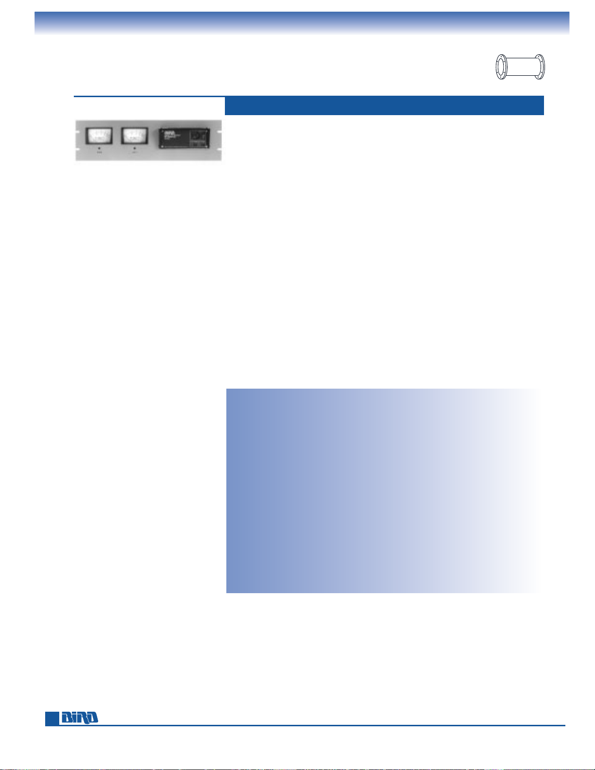
Phone: 440-248-1200 • Fax: 440-248-5426
32
THRULINE
®
RF DIRECTIONAL WATTMETERS
High-Speed WATTCHER®RF Monitoring Systems
Bird’s high-speed WATTCHER®Systems can protect your transmitting equipment
from damage caused by high-standing waves and warn you about low transmit
power. Our 3171A Series instruments offer ultra-fast response time and a forward
power drop-off alarm in addition to the reflected power monitor/alarm capabilities
of the WATTCHER
®
models on the next page. Two models are available: the Model
3171A (100 W – 250 kW) and Model 3171A-020 (300 W – 60 kW).
Both solid state models can warn a remote operator of: 1) low power due to
detuning, component deterioration, or AC line difficulties; and 2) high reflected
power due to factors such as antenna icing, transmission line problems, physical
accidents and lightning strikes. The 3171A Series:
■
Displays a continuous, simultaneous view of forward and reflected
power which can be remoted.
■
Provides fast fault response time – 250 times faster than other monitors –
for forward and reflected power monitoring.
■
Alerts you to forward power drop-off below a set level
(e.g. to conform to appropriate FCC requirements).
■
Activates audible/visual alarms when reflected power increases.
■
Allows remote reset in the event of a false alarm or momentary
disturbance which leaves transmission unimpaired.
■
Operates from AC or DC.
HIGH-SPEED, FWD/RFL ALARM WATTCHER
®
MODEL 3171A
MODEL 3171A
Features 25 µs response,
5/10/25 kW meter scales, forward and reflected power
alarms.
Power Range: 100 W to 250 kW using
Bird Plug-in Elements*
Frequency Range: 2 MHz to 1 GHz
Accuracy:
±
5% of full scale
Meter Scales:
3171A: FWD and RFL 5/10/25 kW
3171A-020: FWD and RFL 15/30/60 kW
Alarms: Front-panel buzzer, ”Active“
and ”Trip“ LEDs for forward/reflected
Response Time: 25 µs max.
Activate Forward: 73 µs
to 50 ms nominal (adjustable)
Monitor Delay
Front Panel Controls: Reset push-button,
adjust FWD/RFL alarm levels screw.
Rear Panel Features: DC FWD/RFL signal
inputs, main, and remote meter drive
outputs, external 12–16 Vdc supply input,
alarm in/out, reset in/out, AC line voltage
selector, fuse, IEC 320 AC receptacle.
Inputs/Outputs: TTL compatible +5 V logic.
Outputs for remote meter
Cable: Includes two 25 ft. DC cables
AC Power: 115/230 V, 50/60 Hz @ 56 mA max.
DC Power: 12.7 to 16.0 V @ 400 mA max.
Finish: Gray powder coat
Nominal Size: 19" W × 57⁄32" H × 921⁄64" D,
(483 mm
× 133 mm × 237 mm)
Weight: 51⁄2lbs. (2.5 kg)
Required Products:
Line Section: 15⁄8", 31⁄8", 41⁄16",
or 6
1
⁄8" from page 34
Elements (pages 37–38):
3171A: Two from Tables 1
5
⁄8AA,
3
1
⁄8AA, 41⁄16AA, or 61⁄8AA.
3171A-020: Two from Tables 1
5
⁄8BB,
3
1
⁄8BB, 41⁄16BB, or 61⁄8BB.
Cable: If length other than 25 ft. is
desired, order two BNC (M) cables
from page 61.
* Quoted accuracy only when used with other Bird products.
WATTCHERS for 0.1 – 10,000 watt cable systems are found on pages 19–20.
Rigid LineRigid Line
PrProductsoducts
Page 33

E-mail: [email protected] • Internet: www.bird-electronic.com
33
THRULINE
®
RF DIRECTIONAL WATTMETERS
WATTCHER®RF Monitoring Systems
Bird’s WATTCHER®RF monitoring and alarm systems can automatically activate
a variety of safety and equipment protection measures when they detect an
abnormal antenna system load condition. Besides providing simultaneous displays
of forward and reflected power, these instruments signal audible and visual alarms
if reflected power exceeds the limit you set for more than 50 ms. A DPDT interlock
relay can also be wired to shutdown the transmitter, activate deicing equipment,
signal a remote alarm and initiate other measures to protect your equipment from
high VSWR.
The Model 3126A monitors power from 300 W to 60 kW. The Model 3127A covers
systems that output 100 W to 250 kW of RF power. Both models have been refined
over the previous 3126 and 3127 to provide increased performance and user
requested features.
■
Mirrored scale meters aid reading and help eliminate parallax.
■
Separate push-button reset control and LED indicators added.
■
Improved circuitry reduces the chance of false alarms.
■
Can be wired for automatic, unattended reset when alarm
condition clears.
■
Rear connection panel speeds installation or removal.
■
Tested and found EMC compliant.
100 W – 250 kW WATTCHER
®
MODELS 3126A, 3127A
MODEL 3127A
Features a reflected power
alarm for 100 W to 250 kW
RF systems.
Power Range:
3126A: 300 W to 60 kW using Bird
Plug-in Elements*
3127A: 100 W to 250 kW using Bird
Plug-in Elements*
Frequency Range: 2 MHz to 1 GHz
Accuracy:
±
5% of full scale
Meter Scale FWD:
3126A: 15/30/60 kW
3127A: 5/10/25 kW
Meter Scale RFL:
3126A: 1.5/3/6 kW
3127A: 1/2.5/5 kW
Meter Sensitivity: 100 µA/3000Ω
Alarms: Front panel buzzer and red LED
Front Panel Controls: Reset push-button,
reflected power limit display button,
adjust alarm level recessed screw
Rear Panel Features: FWD/RFL DC signal
inputs (BNC), DC power/remote reset
connector, DPDT interlock relay connector,
fail-safe/nonfail-safe selector, alarm
buzzer disable, AC line voltage selector,
safety fuses and IEC 320 AC receptacle.
Cable: Includes two 25 ft. DC cables
AC Power: 115/230 V, 50/60 Hz, @ 0.125 A
DC Power: 9 to 16 V @ 1A
Finish: Gray powder coat
Nominal Size: 19" W × 57⁄32" H × 33⁄4" D
(483 mm
× 133 mm × 95 mm)
Weight: 5 lbs. (2.28 kg)
Required Products:
Line Section: 15⁄8", 31⁄8", 41⁄16",
6
1
⁄8" from page 34
Elements (pages 37–38):
3126A: Two from Tables 1
5
⁄8 B, 31⁄8 B,
4
1
⁄16B, or 61⁄8B
3127A: Two from Tables 1
5
⁄8A, 31⁄8A,
4
1
⁄16A, or 61⁄8A
Cable: If length other than 25 ft. is
desired, order two BNC (M) cables
from page 61.
* Quoted accuracy only when used with other Bird products.
WATTCHERS for 0.1 – 10,000 watt cable systems are found on pages 19–20.
Rigid LineRigid Line
PrProductsoducts
Page 34
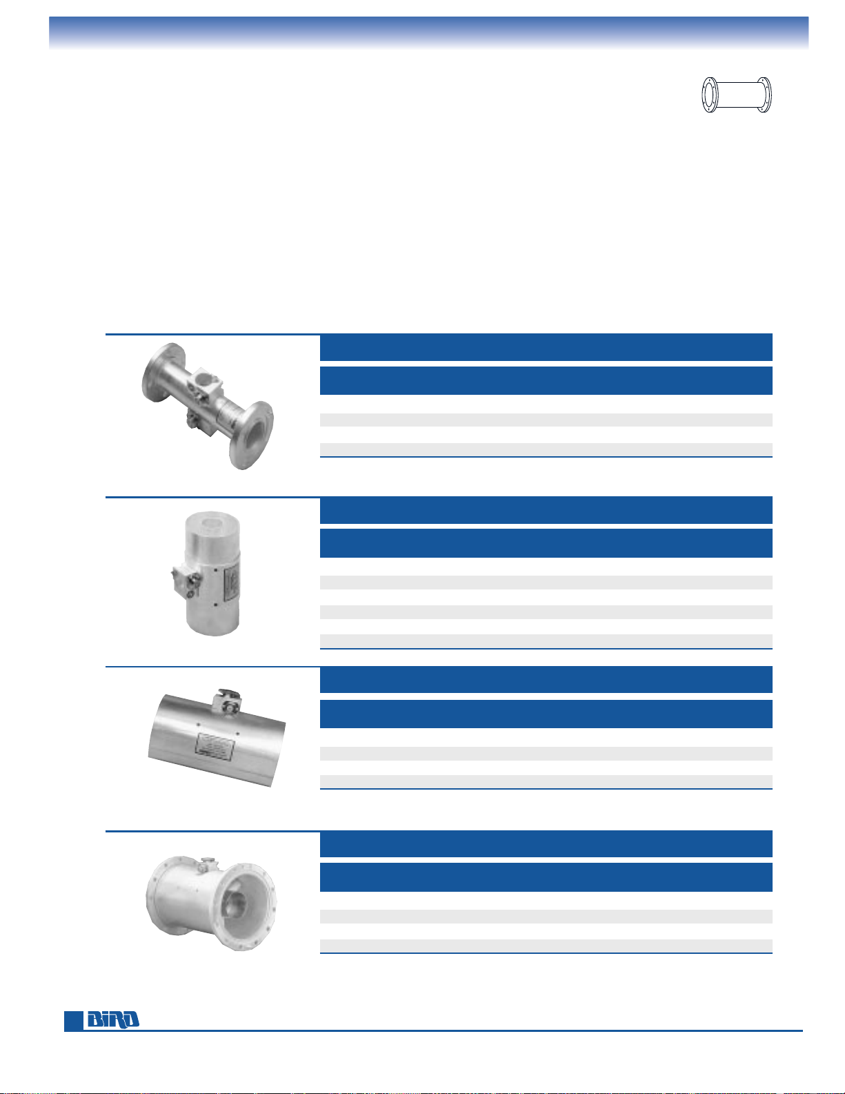
Phone: 440-248-1200 • Fax: 440-248-5426
34
THRULINE
®
WATTMETER COMPONENTS
Rigid Line Sections
Bird offers 15⁄8", 31⁄8", 41⁄16", and 61⁄8" RF air line sections which, with the appropriate meter and Plug-in Elements, form a
complete power measurement system. These precision sections insert in the transmission line, between the
transmitter and antenna or load, and are available with flanged, unflanged/flush, or unflanged/recessed connections.
Line sections contain one element socket, or dual opposing sockets. Dual socket models permit forward and reflected
readings using just one line section and a switchable meter or dual-meter panel.
Plug-in Elements (pages 36–38) must be ordered according to the desired frequency and power ranges, line section size,
and the scales of the meter selected for use with the line section:
■
5/10/25 Scales: Element Tables 15⁄8 A, 31⁄8 A, 41⁄
16
A, 61⁄8 A
■
15/30/60 Scales: Element Tables 15⁄8 B, 31⁄8 B, 41⁄
16
B, 61⁄8 B
■
8/80 Scales: Element Tables 15⁄8 C, 31⁄8 C, 41⁄
16
C, 61⁄8 C
15⁄8" RIGID LINE SECTIONS
MODEL
LINE CONNECTOR ELEMENT LENGTH WEIGHT
SIZE TYPE SOCKETS (INCHES) (LBS.)
4712-000 15⁄8" EIA Flg. 1 6.75 3
4715-000 1
5
⁄8" EIA Flg. 2 6.75 3.25
4720-000 1
5
⁄8" UnFlg. (Rec. 0.438") 1 6.38 1.25
4723-000 1
5
⁄8" UnFlg. (Rec. 0.438") 2 6.38 1.5
31⁄8" RIGID LINE SECTIONS
MODEL
LINE CONNECTOR ELEMENT LENGTH WEIGHT
SIZE TYPE SOCKETS (INCHES) (LBS.)
4600-000 31⁄8 EIA Flg. 1 7.03 7
4610-000 3
1
⁄8" EIA Flg. 2 7.03 7.25
4801-000 3
1
⁄8" UnFlg. (Rec. 0.688") 1 6.5 4
4801-100 3
1
⁄8" UnFlg. (Rec. 0.688") 2 6.5 4.25
4802-000 3
1
⁄8" UnFlg. (Flush) 2 6.5 4.25
4805-000 3
1
⁄8" UnFlg. (Flush) 1 6.5 4
41⁄16" RIGID LINE SECTIONS
MODEL
LINE CONNECTOR ELEMENT LENGTH WEIGHT
SIZE TYPE SOCKETS (INCHES) (LBS.)
4641-000 41⁄16" EIA Flg. 1 8.38 8.63
4642-000 4
1
⁄16" EIA Flg. 2 8.38 8.88
4843-000 4
1
⁄16" UnFlg. (Rec. 0.531") 1 7.5 2.63
4844-000 4
1
⁄16" UnFlg. (Rec. 0.531") 2 7.5 2.88
61⁄8" RIGID LINE SECTIONS
MODEL
LINE CONNECTOR ELEMENT LENGTH WEIGHT
SIZE TYPE SOCKETS (INCHES) (LBS.)
4902-000 61⁄8" EIA Flg. 1 10.22 16.75
4905-000 6
1
⁄8" EIA Flg. 2 10.22 17
4907-000 6
1
⁄8" UnFlg. (Rec. 0.968") 1 9.63 12.5
4909-000 6
1
⁄8" UnFlg. (Rec. 0.968") 2 9.63 12.75
MODEL 4715-000
MODEL 4805-000
MODEL 4843-000
MODEL 4902-000
Rigid LineRigid Line
PrProductsoducts
Page 35
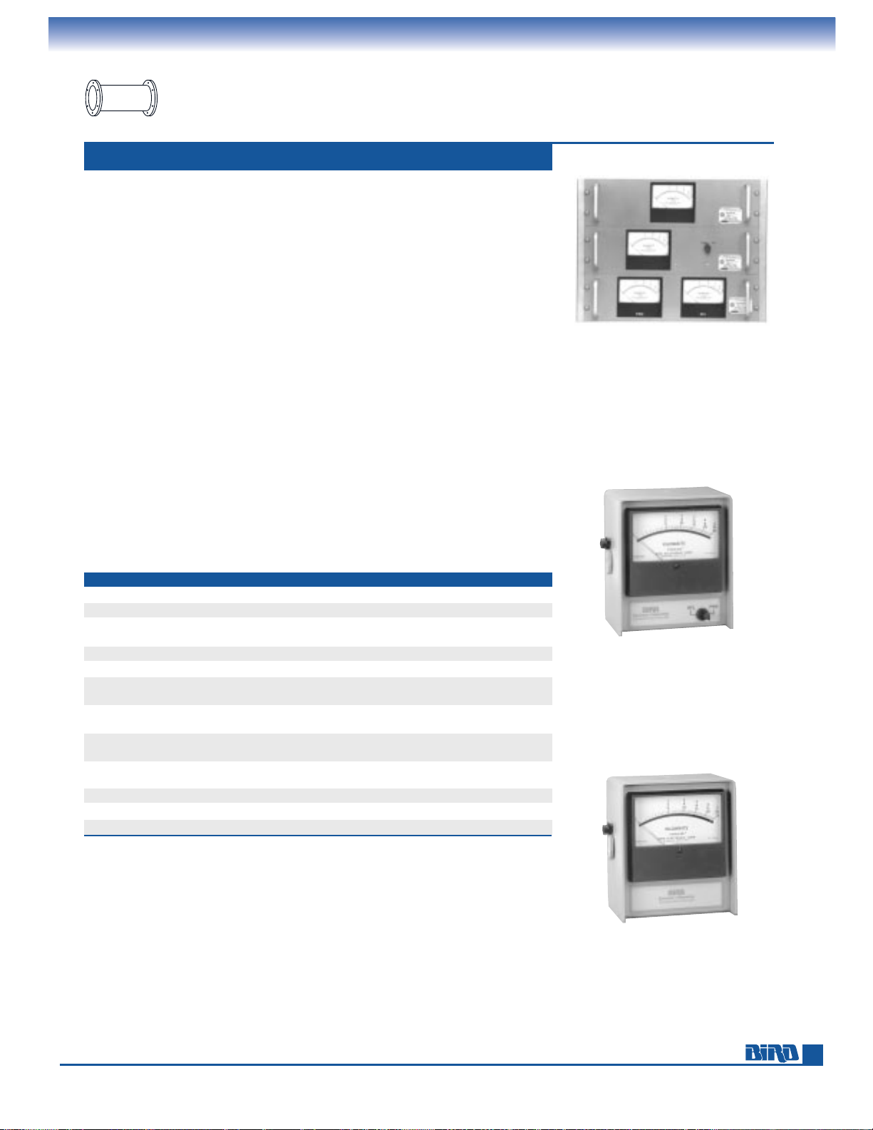
E-mail: [email protected] • Internet: www.bird-electronic.com
35
THRULINE
®
WATTMETER COMPONENTS
Meters for Rigid Line Use
The 100 µA meters presented on this page form a complete power measurement
system when combined with the appropriate 1
5
⁄8", 31⁄8", 41⁄16", or 61⁄8" rigid line sec-
tion (page 34) and Plug-in Elements (pages 36–38).
The 3127 Series meters are available in six 19" panel-mount configurations with
dual meters, single meter, or single meter with forward/reflected power switch.
Scale choices include 15/30/60 kW and 5/10/25 kW.
The 6810 Series housed meters are offered with a choice of meter scales, with
or without a forward/reflected power switch. Scale choices include 15/30/60 kW,
5/10/25 kW, and 8/80 kW. These are the same meters included in the complete
high-power wattmeter packages on pages 30–31.
Plug-in Elements must be ordered according to the desired frequency and power
ranges, the meter scales, and size of the line section selected for use with the meter:
■
5/10/25 Scales: Element Tables 15⁄8 A, 31⁄8 A, 41⁄
16
A, 61⁄8 A
■
15/30/60 Scales: Element Tables 15⁄8 B, 31⁄8 B, 41⁄
16
B, 61⁄8 B
■
8/80 Scales: Element Tables 15⁄8 C, 31⁄8 C, 41⁄
16
C, 61⁄8 C
(6810 Series, only)
DIMENSIONS AND WEIGHT:
■
3127 Series Panel-Mount Meters: 19" W × 57⁄32" H × 43⁄8" D,
(483 mm
× 133 mm ×112 mm). Weight: 3 lbs. (1.4 kg)
■
6810 Series Housed Meters: 59⁄16" W × 61⁄2" H × 33⁄8" D,
(142 mm
× 166 mm ×86 mm). Weight: 3 lbs. (1.4 kg)
METERS 3127, 6810 SERIES
MODEL TYPE SCALES DC CABLE (FT.) USES LINE SECTION
3127-035 Single 41⁄2" rectangular on panel 5/10/25 kW 25 Single socket from page 34
3127-040 Dual 4
1
⁄2" rectangular on panel 5/10/25 kW 25 Double socket from page 34
3127-055 Single 4
1
⁄2" rectangular 5/10/25 kW 25 Double socket from page 34
on panel w/fwd. and rfl. switch
3127-070 Single 4
1
⁄2" rectangular on panel 15/30/60 kW 25 Single socket from page 34
3127-075 Dual 4
1
⁄2" rectangular on panel 15/30/60 kW 25 Double socket from page 34
3127-080 Single 4
1
⁄2" rectangular 15/30/60 kW 25 Double socket from page 34
on panel w/fwd. and rfl. switch
6810-220 4
1
⁄2" rectangular in 5/10/25 kW 10 Double socket from page 34
housing w/fwd. and rfl. switch
6810-230 4
1
⁄2" rectangular in 15/30/60 kW 10 Double socket from page 34
housing w/fwd. and rfl. switch
6810-250 4
1
⁄2" rectangular in 8/80 kW 10 Double socket from page 34
housing w/fwd. and rfl. switch
6810-265 4
1
⁄2" rectangular in housing 8/80 kW 10 Single socket from page 34
6810-307 4
1
⁄2" rectangular in housing 15/30/60 kW 10 Single socket from page 34
6810-309-7 4
1
⁄2" rectangular in housing 5/10/25 kW 10 Single socket from page 34
Top to Bottom:
MODEL 3127-070,
MODEL 3127-055,
MODEL 3127-040
MODEL 6810-220
MODEL 6810-309-7
Elements for rigid line wattmeters are found on pages 36–38
Rigid LineRigid Line
PrProductsoducts
Page 36
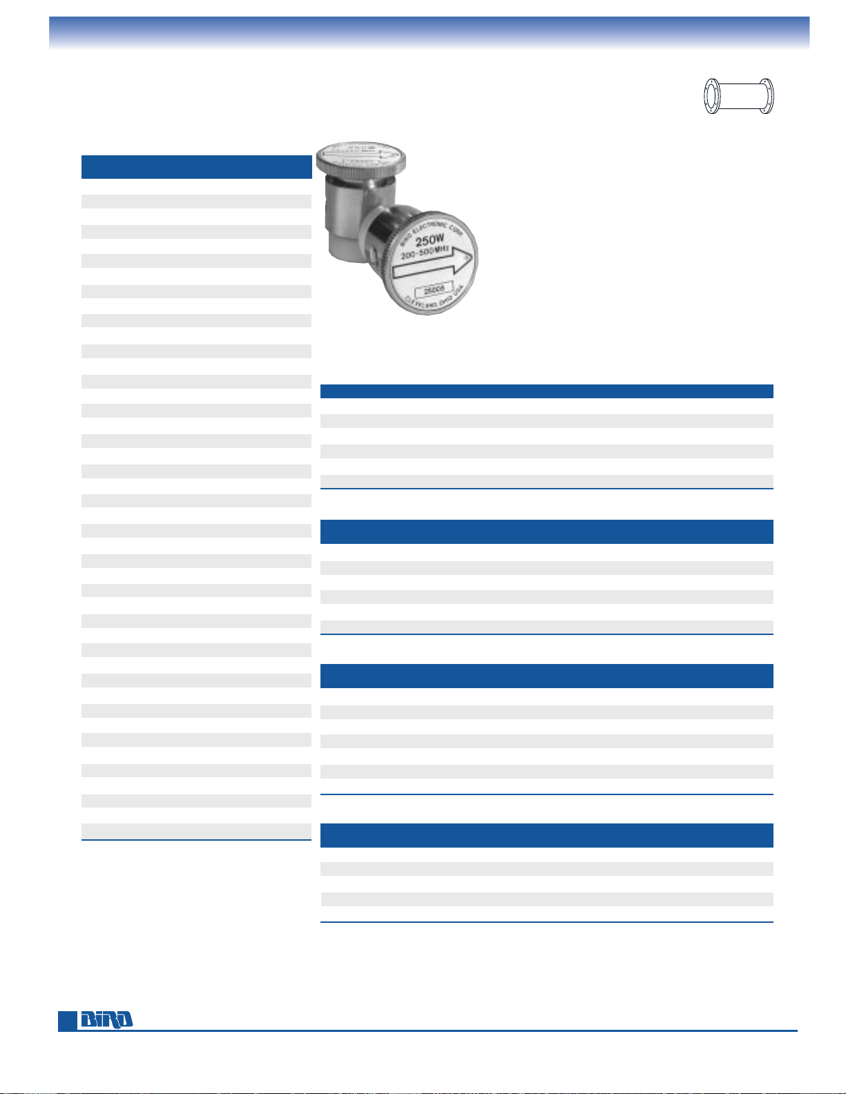
Phone: 440-248-1200 • Fax: 440-248-5426
36
PLUG-IN ELEMENTS
Selection Guides – Standard and Low Power
WATTMETER* SELECT ELEMENT
MODEL FROM TABLE(S)
3126A 15⁄8 B, 31⁄8 B, 41⁄16 B, 61⁄8 B
3127A 1
5
⁄8 A, 31⁄8 A, 61⁄8 A
3127-035 1
5
⁄8 A, 31⁄8 A, 41⁄16A, 61⁄8 A
3127-040 1
5
⁄8 A, 31⁄8 A, 41⁄16A, 61⁄8 A
3127-055 1
5
⁄8 A, 31⁄8 A, 41⁄16A, 61⁄8 A
3127-070 1
5
⁄8 B, 31⁄8 B, 41⁄16 B, 61⁄8 B
3127-075 1
5
⁄8 B, 31⁄8 B, 41⁄16 B, 61⁄8 B
3127-080 1
5
⁄8 B, 31⁄8 B, 41⁄16 B, 61⁄8 B
3171A 1
5
⁄8 AA, 31⁄8 AA, 41⁄16 A A, 61⁄8 AA
3171-020 1
5
⁄8 BB, 31⁄8 BB, 41⁄16 BB, 61⁄8 BB
4305A 8**, 1
5
⁄8AA
4382, 84, 86, 88 1
5
⁄8 A, 31⁄8 A, 61⁄8 A
460A 3
1
⁄8 A
4600-037A 3
1
⁄8 B
4610-200A 3
1
⁄8 A
4610-300A 3
1
⁄8 B
4641A 4
1
⁄16 A
4641-037A 4
1
⁄16 B
4641-080A 4
1
⁄16 C
4642-200A 4
1
⁄16 A
4642-300A 4
1
⁄16 B
4643-080A 4
1
⁄16 C
4712A 1
5
⁄8 A
4712-037A 1
5
⁄8 B
4715-200A 1
5
⁄8 A
4715-300A 1
5
⁄8 B
4720A 1
5
⁄8 A
4723-200A 1
5
⁄8 A
4802-200A 3
1
⁄8 A
4802-300A 3
1
⁄8 B
4805A 3
1
⁄8 A
4805-037A 3
1
⁄8 B
4843A 4
1
⁄16 A
4843-037A 4
1
⁄16B
4844-200A 4
1
⁄16 A
4844-300A 4
1
⁄16 B
4902A 6
1
⁄8 A
4902-037A 6
1
⁄8 B
4902-080A 6
1
⁄8 C
4905-200A 6
1
⁄8 A
4905-300A 6
1
⁄8 B
4907A 6
1
⁄8 A
4907-080A 6
1
⁄8 C
4909-200A 6
1
⁄8 A
* In addition to the elements listed, these meters can use Tables 15, 16 and17 coupler elements for RF sampling.
The instrument meter does not read when these elements are installed. Typically, Table 15–17 elements are
used with line sections, but also provide RF sampling when used with metered instruments where the meter
simply serves as a line section. Directional coupler power ratings cannot exceed the peak and average
rating of the transmission line.
** See page 27 for Table 8
ELEMENT TABLE VS. METER SENSITIVITY AND SCALES
ELEMENT TABLE METER CURRENT METER SCALE
15⁄8A, 31⁄8A, 41⁄16A, 61⁄8A 100 µA 5/10/25
1
5
⁄8AA, 31⁄8AA, 41⁄16AA, 61⁄8AA 30 µA 5/10/25
1
5
⁄8B, 31⁄8B, 41⁄16B, 61⁄8B 100 µA 15/30/60
1
5
⁄8BB, 31⁄8BB, 41⁄16BB, 61⁄8BB 30 µA 15/30/60
1
5
⁄8C, 31⁄8C, 41⁄16C, 61⁄8C 100 µA 80
15, 16, 17* — —
The Bird Plug-In Elements on these pages are for wattmeters
used with rigid line sections (See pages 25–28 for 50-ohm cable
wattmeter elements). Use the Selection Guide on this page or
call us for assistance to find the right element.
Except for directional coupler elements, all 1
5
⁄8" to
6
1
⁄8" rigid line elements must be calibrated with
the wattmeter where they will be used to ensure
stated accuracy. We highly recommend ordering
elements in identical pairs, recording the meter
reading of both and storing one in a safe place.
This will help you avoid the inconvenience of
returning an entire wattmeter for recalibration
(e.g., if an element is dropped.)
Always specify your wattmeter or line section number when ordering elements.
ELEMENT SELECTION GUIDE
FREQUENCY NOMINAL MAX. MAIN
BAND (MHz) COUPLING LINE POWER
MODEL
50–100 –50 dB 10 kW 501-50
75–150 –50 dB 10 kW 501-75
125–250 –50 dB 10 kW 501-125
225–450 –50 dB 10 kW 501-225
400–800 –50 dB 5 kW 501-400
750–1250 –50 dB 5 kW 501-750
TABLE 15 DIRECTIONAL COUPLER ELEMENTS FOR 15⁄8" EIA LINES
FREQUENCY NOMINAL MAX. MAIN
BAND (MHz) COUPLING LINE POWER
MODEL
25–40 –55 dB 25 kW 553-25
50–100 –55 dB 25 kW 553-50
75–150 –55 dB 25 kW 553-75
125–250 –55 dB 25 kW 553-125
225–450 –55 dB 25 kW 553-225
400–800 –55 dB 15 kW 553-401
750–1250 –55 dB 10 kW 553-750
TABLE 16 DIRECTIONAL COUPLER ELEMENTS FOR 31⁄8" EIA LINES
FREQUENCY NOMINAL MAX. MAIN
BAND (MHz) COUPLING LINE POWER
MODEL
50–100 –60 dB 60 kW 606-50
75–150 –60 dB 60 kW 606-75
125–250 –60 dB 60 kW 606-125
225–450 –60 dB 60 kW 606-225
400–870 –60 dB 60 kW 606-400
TABLE 17 DIRECTIONAL COUPLER ELEMENTS FOR 61⁄8" EIA LINES
Rigid LineRigid Line
PrProductsoducts
Page 37
E-mail: [email protected] • Internet: www.bird-electronic.com
37
PLUG-IN ELEMENTS
For 15⁄8" and 31⁄8" Lines
POWER FREQUENCY BANDS (MHz)
RANGE 2-30 25-60 50-125 100-250 200-500 400-1000
100 W — 100A1 100B1 100C1 100D1 100E1
250 W — 250A1 250B1 250C1 250D1 250E1
500 W — 500A1 500B1 500C1 500D1 500E1
1000 W — 1000A1 1000B1 1000C1 1000D1 1000E1
2500 W 2500H1 2500A1 2500B1 2500C1 2500D1 2500E1
5000 W 5000H1 5000A1 5000B1 5000C1 5000D1 5000E1
10 kW 10KH1 10KA1 10KB1 10KC1 — —
25 kW 25KH1 25KA1 25KB1 — — —
TABLE 15⁄8A STANDARD ELEMENTS 100 µA
ELEMENTS FOR 15⁄8" LINE SECTIONS ELEMENTS FOR 31⁄8" LINE SECTIONS
POWER FREQUENCY BANDS (MHz)
RANGE 2-30 25-60 50-125 100-250 200-500 400-1000
100 W — — 100B3 100C3 100D3 100E3
250 W — — 250B3 250C3 250D3 250E3
500 W — 500A3 500B3 500C3 500D3 500E3
1000 W — 1000A3 1000B3 1000C3 1000D3 1000E3
2500 W 2500H3 2500A3 2500B3 2500C3 2500D3 2500E3
5000 W 5000H3 5000A3 5000B3 5000C3 5000D3 5000E3
10 kW 10KH3 10KA3 10KB3 10KC3 10KD3 10KE3
25 kW 25KH3 25KA3 25KB3 25KC3 25KD3 25KE3
50 kW 50KH3 50KA3 50KB3 50KC3 — —
100 kW 100KH3 — — — — —
TABLE 31⁄8A STANDARD ELEMENTS 100 µA
POWER FREQUENCY BANDS (MHz)
RANGE 2-30 25-60 50-125 100-250 200-500 400-1000
100 W — 100A12 100B12 100C12 100D12 100E12
250 W — 250A12 250B12 250C12 250D12 250E12
500 W 500H12 500A12 500B12 500C12 500D12 500E12
1000 W 1000H12 1000A12 1000B12 1000C12 1000D12 1000E12
2500 W 2500H12 2500A12 2500B12 2500C12 2500D12 2500E12
5000 W 5000H12 5000A12 5000B12 5000C12 5000D12 5000E12
10 kW 10KH12 10KA12 10KB12 10KC12 — —
25 kW 25KH12 25KA12 25KB12 — — —
TABLE 15⁄8AA STANDARD ELEMENTS 30 µA
POWER FREQUENCY BANDS (MHz)
RANGE 2-30 25-60 50-125 100-250 400-1000
300 W — — 300B1 300C1 300E1
600 W — — 600B1 600C1 600E1
1500 W 1500H1 — 1500B1 1500C1 1500E1
3000 W 3000H1 3000A1 3000B1 3000C1 3000E1
6000 W 6000H1 — 6000B1 6000C1 6000E1
15 kW 15KH1 — 15KB1 — —
TABLE 15⁄8B STANDARD ELEMENTS 100 µA
POWER FREQUENCY BANDS (MHz)
RANGE 2-30 50-125 100-250 400-1000
300 W 300H12 300B12 300C12 300E12
600 W 600H12 600B12 600C12 600E12
1500 W 1500H12 1500B12 1500C12 1500E12
3000 W 3000H12 3000B12 3000C12 3000E12
6000 W 6000H12 6000B12 6000C12 6000E12
15 kW 15KH12 15KB12 — —
TABLE 15⁄8BB STANDARD ELEMENTS 30 µA
POWER FREQUENCY BANDS (MHz)
RANGE 25-60 50-125 100-250
8000 W 8000A1 8000B1 8000C1
TABLE 15⁄8C STANDARD ELEMENTS 100 µA
POWER FREQUENCY BANDS (MHz)
RANGE 2-30 25-60 50-125 100-250 200-500 400-1000
100 W — 100A32 100B32 100C32 100D32 100E32
250 W — 250A32 250B32 250C32 250D32 250E32
500W 500H32 500A32 500B32 500C32 500D32 500E32
1000 W 1000H32 1000A32 1000B32 1000C32 1000D32 1000E32
2500 W 2500H32 2500A32 2500B32 2500C32 2500D32 2500E32
5000 W 5000H32 5000A32 5000B32 5000C32 5000D32 5000E32
10 kW 10KH32 10KA32 10KB32 10KC32 10KD32 10KE32
25 kW 25KH32 25KA32 25KB32 25KC32 25KD32 25KE32
50 kW 50KH32 50KA32 50KB32 50KC32 — —
100 kW 100KH32 — — — — —
TABLE 31⁄8AA STANDARD ELEMENTS 30 µA
POWER FREQUENCY BANDS (MHz)
RANGE 50-125 100-250 400-1000
600 W 600B3 600C3 600E3
1500 W 1500B3 1500C3 1500E3
3000 W 3000B3 3000C3 3000E3
6000 W 6000B3 6000C3 6000E3
15 kW 15KB3 15KC3 15KE3
30 kW 30KB3 30KC3 30KE3
TABLE 31⁄8B STANDARD ELEMENTS 100 µA
POWER FREQUENCY BANDS (MHz)
RANGE 50-125 100-250 400-1000
600 W 600B32 600C32 600E32
1500 W 1500B32 1500C32 1500E32
3000 W 3000B32 3000C32 3000E32
6000 W 6000B32 6000C32 6000E32
15 kW 15KB32 15KC32 15KE32
30 kW 30KB32 30KC32 30KE32
TABLE 31⁄8BB STANDARD ELEMENTS 30 µA
Note – transmission line power rating should not be exceeded.
POWER FREQUENCY BANDS (MHz)
RANGE 100-250
8000 W 8000C3
TABLE 31⁄8C STANDARD ELEMENTS 100 µA
Rigid LineRigid Line
PrProductsoducts
Page 38
Phone: 440-248-1200 • Fax: 440-248-5426
38
PLUG-IN ELEMENTS
For 41⁄16" and 61⁄8" Lines
POWER FREQUENCY BANDS (MHz)
RANGE 50-125 100-250 400-1000
2500 W 2500B5 2500C5 2500E5
5000 W 5000B5 5000C5 5000E5
10 kW 10KB5 10KC5 10KE5
25 kW 25KB5 25KC5 25KE5
50 kW 50KB5 50KC5 —
TABLE 41⁄16A STANDARD ELEMENTS 100 µA
POWER FREQUENCY BANDS (MHz)
RANGE 50-125 100-250 400-1000
2500 W 2500B52 2500C52 2500E52
5000 W 5000B52 5000C52 5000E52
10 kW 10KB52 10KC52 10K352
25 kW 25KB52 25KC52 25KE52
50 kW 50KB52 50KC52 —
TABLE 41⁄16AA STANDARD ELEMENTS 30 µA
POWER FREQUENCY BANDS (MHz)
RANGE 50-125 100-250 400-1000
3000 W 3000B6 3000C6 3000E6
6000 W 6000B6 6000C6 6000E6
15 kW 15KB6 15KC6 15KE6
30 kW 30KB6 30KC6 30KE6
60 kW 60KB6 60KC6 60KE6
TABLE 61⁄8B STANDARD ELEMENTS 100 µA
POWER FREQUENCY BANDS (MHz)
RANGE 50-125 100-250 400-1000
3000 W 3000B62 3000C62 3000E62
6000 W 6000B62 6000C62 6000E62
15 kW 15KB62 15KC62 15KE62
30 kW 30KB62 30KC62 30KE62
60 kW 60KB62 60KC62 60KE62
TABLE 61⁄8BB STANDARD ELEMENTS 30 µA
POWER FREQUENCY BANDS (MHz)
RANGE 50-125 100-250 400-1000
8000 W 8000B6 8000C6 8000E6
80 kW 80KB6 80KC6 80KE6
TABLE 61⁄8C STANDARD ELEMENTS 100 µA
POWER FREQUENCY BANDS (MHz)
RANGE 50-125 100-250 400-1000
1500 W 1500B5 1500C5 1500E5
3000 W 3000B5 3000C5 3000E5
6000 W 6000B5 6000C5 6000E5
15 kW 15KB5 15KC5 15KE5
30 kW 30KB5 30KC5 30KE5
60 kW 60KB5 60KC5 —
TABLE 41⁄16B STANDARD ELEMENTS 100 µA
POWER FREQUENCY BANDS (MHz)
RANGE 50-125 100-250 400-1000
1500 W 1500B52 1500C52 1500E52
3000 W 3000B52 3000C52 3000E52
6000 W 6000B52 6000C52 6000E52
15 kW 15KB52 15KC52 15KE52
30 kW 30KB52 30KC52 30KE52
60 kW 60KB52 60KC52 —
TABLE 41⁄16BB STANDARD ELEMENTS 30 µA
POWER FREQUENCY BANDS (MHz)
RANGE 50-125 100-250 400-1000
8000 W 8000B5 8000C5 8000E5
80 kW 80KB5 80KC5 —
TABLE 41⁄16C STANDARD ELEMENTS 100 µA
ELEMENTS FOR 41⁄16" LINE SECTIONS
POWER FREQUENCY BANDS (MHz)
RANGE 2-30 25-60 50-125 100-250 200-500 400-1000
1000 W — 1000A6 1000B6 1000C6 1000D6 1000E6
2500 W — 2500A6 2500B6 2500C6 2500D6 2500E6
5000 W — 5000A6 5000B6 5000C6 5000D6 5000E6
10 kW 10KH6 10KA6 10KB6 10KC6 10KD6 10KE6
25 kW 25KH6 25KA6 25KB6 25KC6 25KD6 25KE6
50 kW 50KH6 50KA6 50KB6 50KC6 50KD6 50KE6
100 kW 100KH6 100KA6 100KB6 100KC6 — —
250 kW 250KH6 — — — — —
TABLE 61⁄8A STANDARD ELEMENTS 100 µA
POWER FREQUENCY BANDS (MHz)
RANGE 2-30 25-60 50-125 100-250 200-500 400-1000
250 W — 250A62 250B62 250C62 250D62 250E62
500 W — 500A62 500B62 500C62 500D62 500E62
1000 W 1000H62 1000A62 1000B62 1000C62 1000D62 1000E62
2500 W 2500H62 2500A62 2500B62 2500C62 2500D62 2500E62
5000 W 5000H62 5000A62 5000B62 5000C62 5000D62 5000E62
10 kW 10KH62 10KA62 10KB62 10KC62 10KD62 10KE62
25 kW 25KH62 25KA62 25KB62 25KC62 25KD62 25KE62
50 kW 50KH62 50KA62 50KB62 50KC62 50KD62 50KE62
100 kW 100KH62 100KA62 100KB62 100KC62 — —
250 kW 250KH62 — — — — —
TABLE 61⁄8AA STANDARD ELEMENTS 30 µA
ELEMENTS FOR 61⁄8" LINE SECTIONS
Note – transmission line power rating should not be exceeded.
Rigid LineRigid Line
PrProductsoducts
Page 39
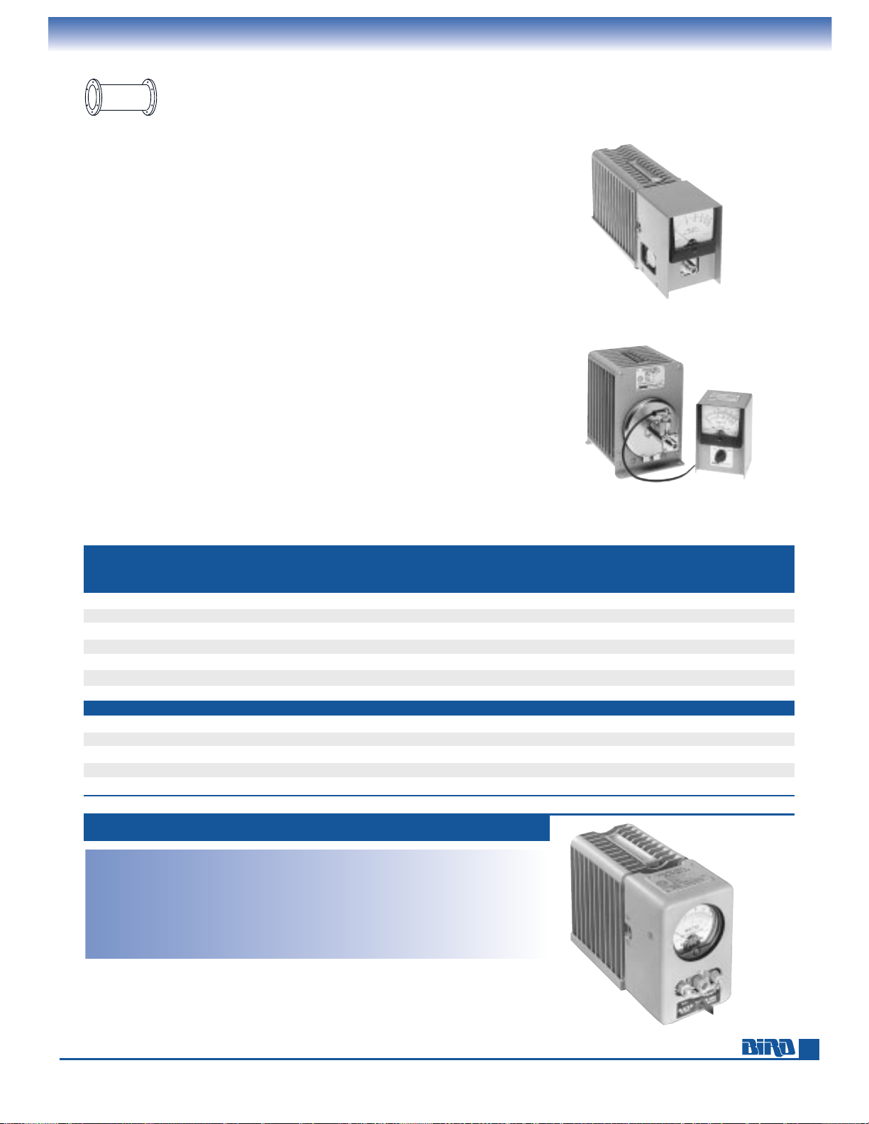
E-mail: [email protected] • Internet: www.bird-electronic.com
39
TERMALINE
®
RF ABSORPTION WATTMETERS
Selection Guide, 60 Watt
Absorption wattmeters were first produced by Bird in 1948 and we continue
to refine these instruments.
TERMALINE
®
Absorption Wattmeters give you the convenience of a combination
measuring and terminating unit for servicing 50-ohm systems. These instruments
consist of a direct-reading meter and load resistor that dissipates RF power during
measurement. Their individual frequency coverage is generally wider than that of
directional meters.
Power ratings range from 150 watts to 2500 watts, and are conservative rated.
Most of the Models have been purchased under U.S., European or Middle East
military standards.
The 6730 Series absorption wattmeters feature a choice of three power ranges
selected through a rotary switch.
The 6100 Series wattmeters and load sections are joined with Bird latch connectors
which permit easy separation. This feature allows use of the resistor as an independent termination.
Use the Selection Guide below to find the absorption wattmeter best for
your needs.
ABSORPTION WATTMETER SELECTION GUIDE
RATING RANGE MHz
1000 W 25–1000
1000 W 1.5–35
1200 W 25–1000
2500 W 25–1000
2500 W 1.5–35
20 25 30 50 60 100 120 150 250 500 MODEL PAGE
• • 6104 39
• • • 6151A 40
• • 6154 40
• • 6156 40
• • 6732B 40
• • • 6734B 40
• • • 6734B030 40
50 100 120 250 500 600 1000 1200 2500 MODEL PAGE
• • • 6736A 41
• • • 6736-030A 41
• • • 6735-300A 41
• • • 6737A 41
• • • 6737-030A 41
60 WATT MODEL 6104
Power Range: 60 W
Power Scales: 2/6/20/60 W
Frequency Range and VSWR:
1.1 max. 25–512 MHz
Accuracy:
±
5% of full scale
Connector: Female N
Load Coolant: 0.1 gal (378.5 ml) refined
mineral oil
Finish: Gray powder coat
Nominal Size: (includes connector)
9
5
⁄8" L × 63⁄8" H × 35⁄16" W
(244 mm
× 162 mm × 100 mm)
Weight: 7 lbs. (3.2 kg)
Meter Housing: Can be detached from load
for convenient reading. 3 ft. cable
See our connector adapter kits on page 61.
*FULL
SCALE CALIBRATED
POWER FREQUENCY
RATING RANGE MHz 0.2 0.8 1 2 2.5 3 5 6 10 15
60 W 25–512 • •
100 W 2–2700 • • • •
150 W 25–1000 • •
150 W 25–512 • •
250 W 25–1000 •
500 W 25–1000
500 W 1.5–35
POWER SCALES IN WATTS
60–150 watts
Pages 39–40
250–2500 watts
Pages 40–41
Rigid LineRigid Line
PrProductsoducts
Page 40
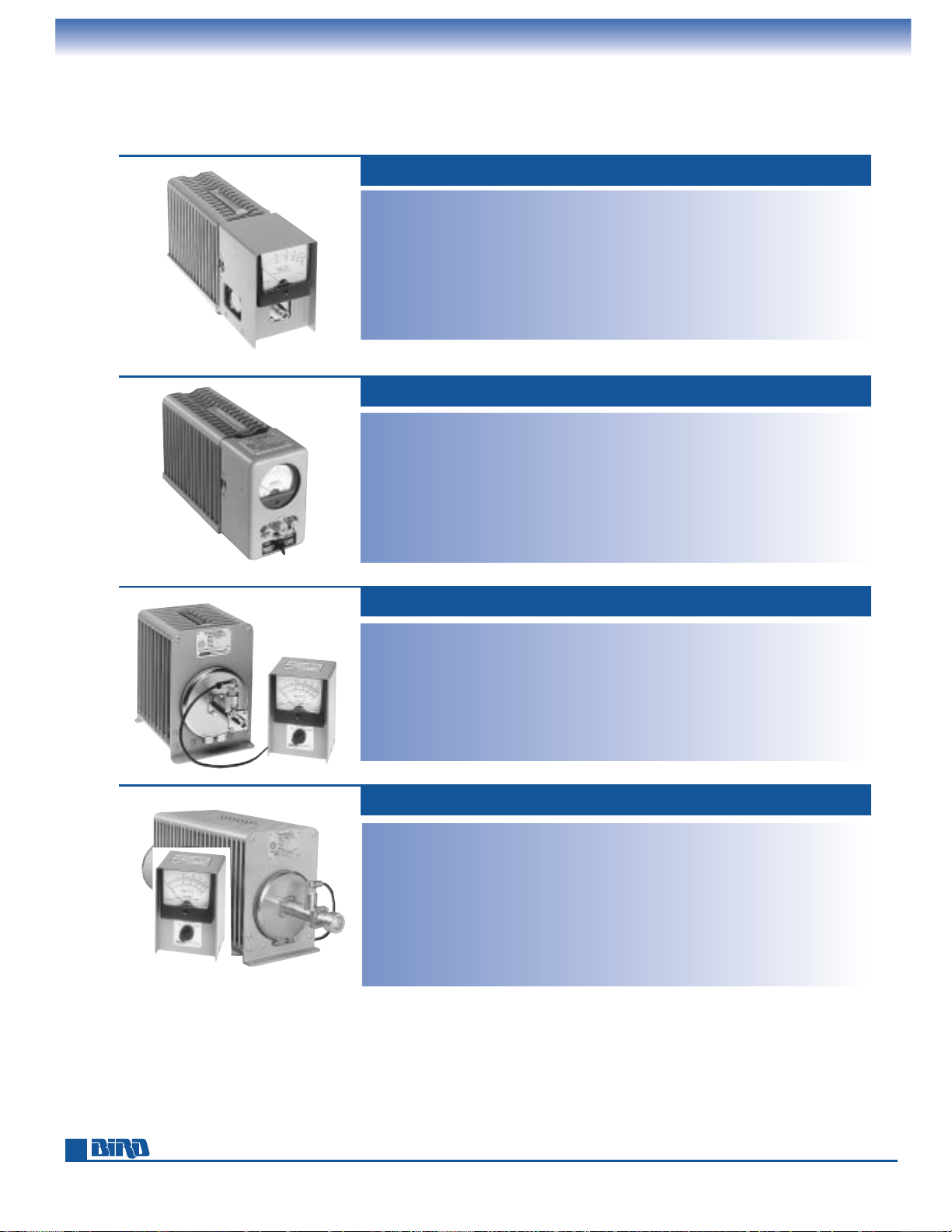
Phone: 440-248-1200 • Fax: 440-248-5426
40
TERMALINE
®
RF ABSORPTION WATTMETERS
100, 150, 250, 500 Watt
100 WATT MODEL 6151A
Power Rating: Up to 100 W depending
on element*
Frequency Range: 2–2700 MHz depending
on element*
Power Scales: 1/2.5/5/10/25/50/100 W
determined by plug-in element*
VSWR: 1.1 max. DC-1000 MHz, 1.25 min.
1000–2300 MHz
Accuracy:
±
5% of full scale to 1 GHz, ±8%
to 2.3 GHz
Connector: QC type (Female N normally
supplied)
Load Coolant: 1 pint (473 ml) refined
mineral oil
Finish: Gray powder coat
Nominal Size: 127⁄8" L × 63⁄8" H × 315⁄16" W
(326 mm
× 162 mm × 100 mm)
Weight: 8 lbs. (3.6 kg)
Elements: Tables 1, 2, 3 on pages 25–26.
*Select plug-in element(s) to suit your frequency and power range.
Do not exceed the power rating of the element or 100 W, whichever is less.
150 WATT MODELS 6154, 6156
Power Rating: 150 W
Power Scales: 5/15/50/150 W
Frequency Range and VSWR:
6154: 1.1 max. 25–1000 MHz
6156: 1.1 max. 25–512 MHz
Accuracy:
6154: ±5% of full scale 25–512 MHz,
±
10% of full scale 512–1000 MHz
6156: ±5% of full scale 25–512 MHz
Connector: Female N
Load Coolant: 0.1 gal (378.5 ml) refined
mineral oil
Finish: Gray powder coat
Nominal Size: (includes connector)
12
5
⁄32" L × 63⁄8" H × 315⁄16" W
(309 mm
× 162 mm × 100 mm)
Weight: 8 lbs. (3.6 kg)
Meter Housing: Separates from load for
convenient reading. 3 ft. cable.
250 WATT MODEL 6732B
Power Rating: 250 W
Power Scales: 10/50/250 W
Frequency Range and VSWR:
1.1 max. 25–1000 MHz
Accuracy:
±
5% of full scale 25–512 MHz,
±
10% of full scale 512–1000 MHz
Connector: QC type
(Female N normally supplied)
Load Coolant: 0.35 gal. (1.3 liters) silicone oil
Finish: Gray powder coat
Nominal Size: Load 125⁄8" L × 81⁄2" W ×
515⁄16" H (321 mm × 216 mm × 151 mm);
Meter 5
7
⁄8" H × 35⁄8" W × 315⁄16" D ,
(149 mm
× 92 mm × 100 mm)
Weight: 13 lbs., 11 oz. (6.2 kg)
Meter: Separates from load for convenient
reading. 4 ft. cable.
500 WATT MODELS 6734B, 6734B030
Power Rating: 500 W
Power Scales: 25/100/500 W
Frequency Range and VSWR:
6734B: 1.15 max. 25–1000 MHz
6734B030: 1.15 max. 1.5–35 MHz
Accuracy:
6734B: ±5% of full scale, 25–512 MHz,
±
10% of full scale, 512–1000 MHz
6734B030: ±10% of full scale, 1.5–35 MHz
Connector: QC type
(Female N normally supplied)
Load Coolant: 0.9 gal. (3.4 liters) refined
mineral oil
Finish: Gray powder coat
Nominal Size: Load 1915⁄16"L × 81⁄2"H ×
5-15/16"W (506 mm x 216 mm × 151 mm);
Meter 5
7
⁄8" H × 35⁄8" W × 315⁄16" D,
(149 mm
× 92 mm × 100 mm)
Weight: 23 lbs., 11 oz. (10.6 kg)
Meter: Separates from load for convenient
reading. 4 ft. cable.
Bird oil-dielectric wattmeters have never been and are not now manufactured with
Poly Chlorinated Biphenyls (PCBs).
Page 41
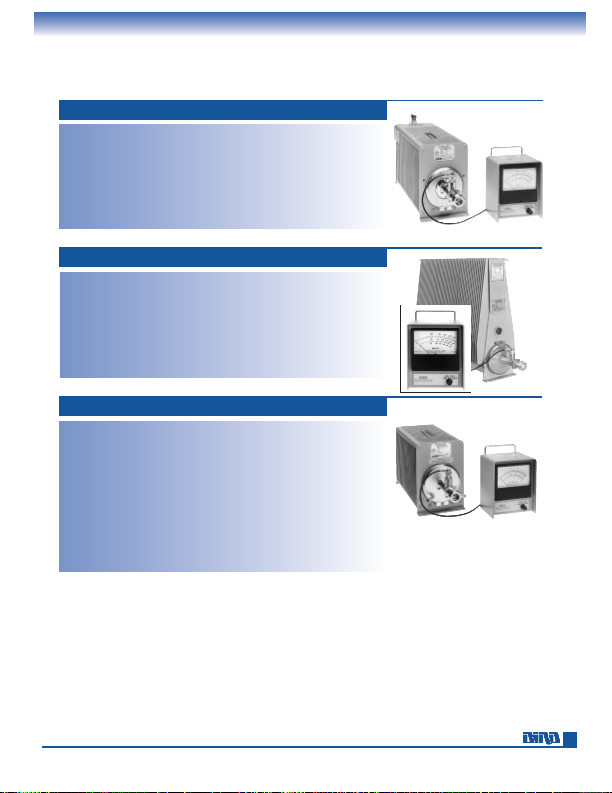
E-mail: [email protected] • Internet: www.bird-electronic.com
41
TERMALINE
®
RF ABSORPTION WATTMETERS
1000, 1200, 2500 Watt
Bird oil-dielectric wattmeters have never been and are not now manufactured with
Poly Chlorinated Biphenyls (PCBs).
1000 WATT MODELS 6736A, 6736-030A
Power Rating: 1000 W
Power Scales: 50/250/1000 W
Frequency Range and VSWR:
6736A: 1.15 max. 25–1000 MHz
6736-030A: 1.15 max.1.5–35 MHz
Accuracy:
6736A: ±5% of full scale, 25–512 MHz,
±
10% of full scale, 512–1000 MHz
6736-030A: ±10% of full scale, 2–32 MHz
Connector: QC type (Female LC normally sup-
plied and Female N supplied unmounted)
Load Coolant: 1.1 gal. (4.1 liters) silicone oil
Finish: Gray powder coat
Nominal Size: Load 21" L × 81⁄2" H ×
515⁄16"W (533 mm x 216 mm x 151 mm);
Meter 5
9
⁄16" H × 61⁄2" W × 311⁄32" D,
(141 mm
× 165 mm × 85 mm)
Weight: 6736A: 30 lbs. (13.5 kg), 6736-030A:
30.5 lbs. (13.7 kg)
Meter: Separates from load for convenient
reading. 4 ft. cable.
1200 WATT MODEL 6735-300A
Power Rating: 1200 W for 1⁄2hour,
1000 W continuous
Power Scales: 120/600/1200 W
Frequency Range and VSWR: 1.15 max.
25–1000 MHz
Accuracy:
±
5% of full scale 25–512 MHz,
±
10% of full scale 512–1000 MHz
Connector: QC type
(Female LC normally supplied, and
Female N supplied unmounted)
Load Coolant: 2.9 gal. (11 liters) refined
mineral oil
Finish: Gray powder coat
Nominal Size: Load 211⁄2" L × 173⁄16" H ×
7" W (546 mm × 437 mm × 178 mm);
Meter 5
9
⁄16" H × 61⁄2" W × 311⁄32" D,
(141 mm
× 165 mm × 85 mm)
Weight: 63 lbs. (28.4 kg)
Meter: Separates from load for convenient
reading. 4 ft. cable.
2500 WATT MODELS 6737A, 6737-030A
Power Rating: 2500 W continuous with
water cooling, 200 W without.
Power Scales: 100/500/2500 W
Frequency Range and VSWR:
6737A: 1.15 max. 25–1000 MHz
6737-030A: 1.15 max. 1.5–35 MHz
Accuracy:
6737A: ±5% of full scale, 25–512 MHz
±
10% of full scale, 512–1000
6737-030A: ±10% of full scale, 2–32 MHz
Connector: QC type
(Female LC normally supplied)
Load Coolant: 0.9 gal. (3.4 liters) refined
mineral oil, water cooled
Water Connections: 3⁄8" tubing to accept
rubber hose
Flow Rate: 1⁄2gpm (2 liters/min)
Operating Position: Vertical - connector
down above 200 W when water cooled
Finish: Gray powder coat
Nominal Size: Load 2013⁄16" L × 81⁄2" H ×
515⁄16" W (529 mm × 216 mm × 151 mm);
Meter 5
9
⁄16" H × 61⁄2" W × 311⁄32" D,
(141 mm
× 165 mm × 85 mm)
Weight: 6737A 33 lbs. (14.9 kg), 6737-030A
33.5 lbs. (15.1 kg)
Meter: Separates from load for convenient
reading. 4 ft. cable.
Page 42

Phone: 440-248-1200 • Fax: 440-248-5426
42
Use this Model Number Definition to specify part numbers when ordering T- and CT-Series dry loads.
TERMALINE
®
RF COAXIAL TERMINATIONS
Product Selection Guide and Model Number Definition
POWER DIELECTRIC COOLING SEE
RATING (CW)
MODEL/SERIES AND INPUT CONNECTOR CHOICES†
MEDIUM METHOD PAGE
2 W 2-T Series BNC (F), BNC (M), N (F), N (M), TNC (F), TNC (M) Air Convection 43
5 W 5-T Series BNC (F), BNC (M), N (F), N (M), TNC (F), TNC (M) Air Convection 43
10 W 10-T Series BNC (F), BNC (M), N (F), N (M), TNC (F), TNC (M) Air Convection 43
25 W 25-T Series BNC (F), BNC (M), N (F), N (M), TNC (F), TNC (M) Air Convection 43
25 W 25-CT Series SMA (M), DMA (M) Air Conduction 43
50 W 50-T Series BNC (F), BNC (M), N (F), N (M), TNC (F), TNC (M) Air Convection 44
50 W 50-CT Series SMA (M), SMA (M) Air Conduction 44
75 W 75-T Series BNC (F), BNC (M), N (F), N (M), TNC (F), TNC (M) Air Convection 44
100 W 100-T Series BNC (F), BNC (M), IEC 7/16 (F), IEC 7/16 (M), N (F), N (M), TNC (F), TNC (M) Air Convection 44
100 W 100-CT Series SMA (F), SMA (M) Air Conduction 44
150 W 150-T Series BNC (F), BNC (M), IEC 7/16 (F), IEC 7/16 (M), N (F), N (M), TNC (F), TNC (M) Air Convection 45
150 W 150-CT Series BNC (F), BNC (M), N (F), N (M), SMA (F), SMA (M), TNC (F), TNC (M) Air Conduction 45
150 W 8135 QC N (F) Oil Convection 45
250 W 250-CT Series BNC (F), BNC (M), N (F), N (M), SMA (F), SMA (M), TNC (F), TNC (M). Air Conduction 45
250 W 8141 QC N (F) Oil Convection 45
300 W 300-T Series BNC (F), BNC (M), IEC 7/16 (F), IEC 7/16 (M), N (F), N (M), TNC (F), TNC (M) Air Convection 46
300 W 8072A-1 N (F) Air Conduction (needs heatsink) 46
500 W 500-CT Series BNC (F), BNC (M), N (F), N (M), SMA (F), SMA (M), TNC (F), TNC (M). Air Conduction 46
For IEC 7/16, specify 500-CT-FE1 for IEC 7/16 (F), or 500-CT-ME1 for IEC 7/16 (M)
500 W 8201 QC N (F) Oil Convection 46
600 W 8401 QC N (F) Oil Convection 47
600 W 8431 SQC N (F) 500 W in horizontal position Air Convection 46
1 kW 8251 QC LC (F), N (F) unmounted Oil Convection 47
1 kW 8833-300 QC LC (F), N (F) unmounted Oil Convection 47
1 kW 8710 Series N (F,M); C (F,M);
7
⁄8" EIA Flg. Air Water (tap) 49
1.5 kW 8860 Series QC LC (F); 1
5
⁄8" and 31⁄8" Unflg. or EIA Flg. Oil Convection 47
2.5 kW 8230 Q LC (F); 200 W without water cooling Oil Water (tap) 47
2.5 kW 8890-300 Series QC LC (F); 1
5
⁄8" and 31⁄8" Unflg. or EIA Flg. Oil Convection 48
5 kW 8890-300 Series plus BA-300 blower 1
1
⁄4 kW with blower turned off, connectors as above Oil Forced Air 48
5 kW 8890-315, –320 Series assembly, connectors as above Oil Forced Air 48
5 kW 8720, 8726 1
5
⁄8" EIA Flg., QC LC (F) Air Water (tap) 50
5 kW 8921 Series QC LC (F), 1
5
⁄8" EIA Flg., 31⁄8" Unflg. or EIA Flg. Oil Convection 49
10 kW 8931-115, –230 Series QC LC (F), 1
5
⁄8" EIA Flg., 31⁄8" Unflg. or EIA Flg. Oil Forced Air 49
10 kW 8730 Series 1
5
⁄8" EIA Flg., 31⁄8" Unflg. or EIA Flg. Air Water (tap) 50
10 kW 8631-115, –230 1
5
⁄8 EIA Flg., 31⁄8" EIA Flg., 31⁄8" Unflg. Air Water/Forced Air 51
10 kW 8578 Series 1
5
⁄8 EIA Flg., 31⁄8" Unflg. Air Forced Air 52
15 kW 8578 Series 1
5
⁄8 EIA Flg., 31⁄8" Unflg. Air Forced Air 52
20 kW 8745/46 3
1
⁄8" EIA Flg., 31⁄8" Unflg. Air Water (tap) 50
25 kW 8572A/73A-115-6, –230-5 3
1
⁄8" EIA Flg., 31⁄8" Unflg. Air Forced Air 53
25 kW 8645-115, –230 3
1
⁄8" EIA Flg., 31⁄8" Unflg. Air Water/Forced Air 51
30 kW 8755/56 3
1
⁄8" EIA Flg., 31⁄8" Unflg. Air Water (tap) 50
40 kW 8765/76 3
1
⁄8" EIA Flg., 31⁄8" Unflg. Air Water (tap) 51
50 kW 8775/76 3
1
⁄8" EIA Flg., 31⁄8" Unflg. Air Water (tap) 51
50 kW 8655/56-115, -230 3
1
⁄8" EIA Flg., 31⁄8" Unflg. Air Water/Forced Air 52
80 kW 8792/93 6
1
⁄8" EIA Flg., 61⁄8" Unflg. Air Water (tap) 51
TERMINATION SELECTION GUIDE
100 – T – FN
Power Rating (Watts)
Product Type
T – Convection-colled Termination
CT – Conduction-cooled Termination
Connector Gender
F – Female
M – Male
Connectors
+
A – SMA
B – BNC
E – IEC 7/16
N – N
T – TNC
† Where QC quick-change or SQC small quick-change connectors are shown, the type listed is normally supplied when no other is specified.
For other choices, see page 60.
* Termination Model Number Definition:
+ Call for custom connector options not shown in this catalog
Page 43
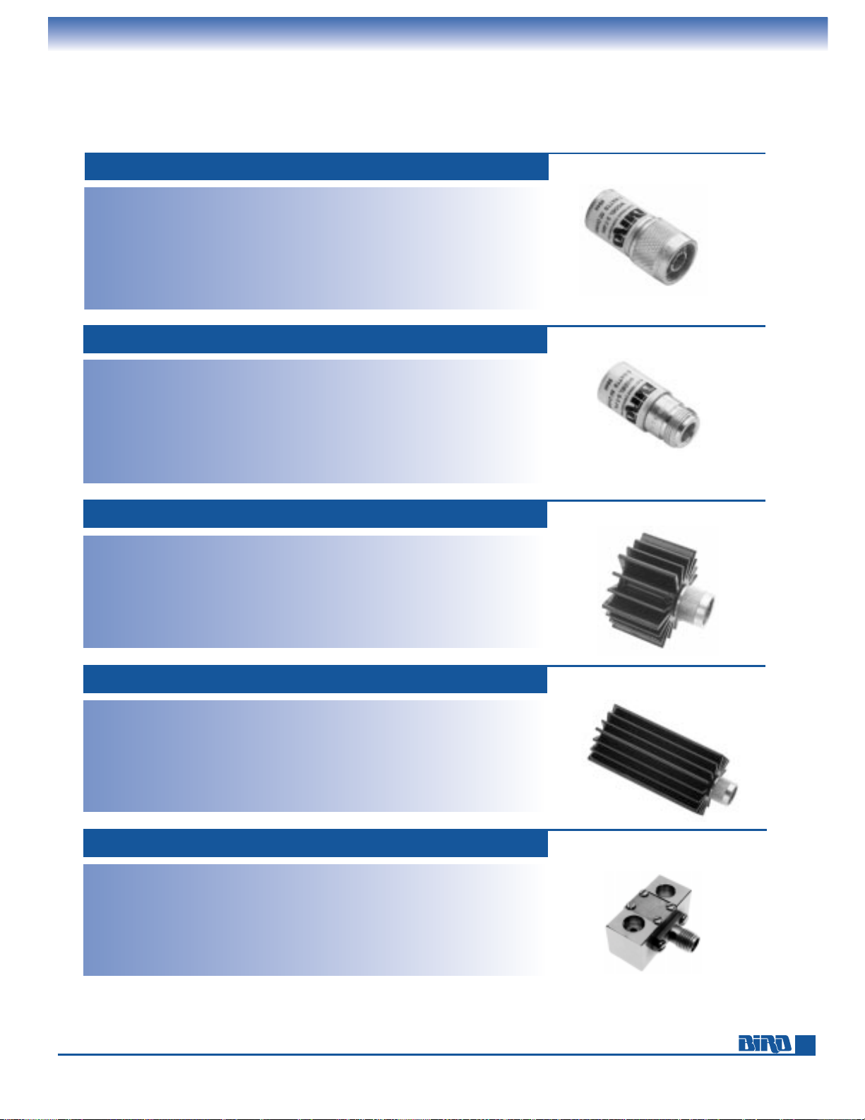
E-mail: [email protected] • Internet: www.bird-electronic.com
43
TERMALINE
®
RF COAXIAL TERMINATIONS
Dry Loads
Power Rating:
5 W max. @ 40°C
6 W max. @ 25°C
Connectors: BNC, N, TNC
Frequency Range and VSWR:
DC to 1 GHz at 1.10:1 max.
1 GHz to 6 GHz at 1.25:1 max. (N type)
1 GHz to 4 GHz at 1.25:1 max.
(BNC and TNC)
Impedance: 50 ohms, nominal
Ambient Temperature Range: –40°C to +40°C
Operating Position: Any
Coolant: Dry (Convection cooled)
Finish: Silver or Tri-alloy plated
Nominal Size: (with Male N-type connector):
1.6" L
× 0.8" Dia., (40.7 mm × 20.4 mm)
Weight: 1.9 oz. (55 g)
5 WATT 5-T SERIES*
Power Rating:
10 W max. @ 40°C
12 W max. @ 25°C
Connectors: BNC, N, TNC
Frequency Range and VSWR:
DC to 1 GHz at 1.10:1 max.
1 GHz to 4 GHz at 1.25:1 max.
Impedance: 50 ohms, nominal
Ambient Temperature Range: –40°C to +40°C
Operating Position: Any
Coolant: Dry (Convection cooled)
Finish: Black anodized.
Silver or Tri-alloy plated connector
Nominal Size: (with N-type connector):
2" L
× 2.3" Dia., (50.8 mm × 58.5 mm )
Weight: 5.1 oz. (146 g)
10 WATT 10-T SERIES*
Power Rating:
25 W max. @ 40°C
30 W max. @ 25°C
Connectors: BNC, N, TNC
Frequency Range and VSWR:
DC to 1 GHz at 1.10:1 max.
1 GHz to 4 GHz at 1.25:1 max.
Impedance: 50 ohms, nominal
Ambient Temperature Range: –40°C to +40°C
Operating Position: Any
Coolant: Dry (Convection cooled)
Finish: Black anodized. Silver or Tri-alloy
plated connector
Nominal Size: (with N-type connector):
4.7" L
× 2.3" Dia., (119.4 mm × 58.5 mm)
Weight: 10.7 oz. (305 g)
25 WATT 25-T SERIES*
Power Rating:
2 W max. @ 40°C
2.4 W max. @ 25°C
Connectors: BNC, N, TNC
Frequency Range and VSWR:
DC to 1 GHz at 1.10:1 max.
1 GHz to 6 GHz at 1.25:1 max. (N type)
1 GHz to 4 GHz at 1.25:1 max.
(BNC and TNC)
Impedance: 50 ohms, nominal
Ambient Temperature Range: –40°C to +40°C
Operating Position: Any
Coolant: Dry (Convection cooled)
Finish: Silver or Tri-alloy plated
Nominal Size: (with Male N-type connector):
1.6" L
× 0.8" Dia., (40.7 mm × 20.4 mm)
Weight: 1.9 oz. (55 g)
2 WATT 2-T SERIES*
NEW
NEW
* See page 42 for a Model Number Definition that instructs you how to order the correct part.
** When mounted to a suitable heatsink capable of maintaining a 100°C flange temperature.
Power Rating:**25 W max. @ 100°C flange
temperature, derated to 0 W @ 150°C.
Frequency Range and VSWR:
DC to 1 GHz at 1.15:1 max.
1 GHz to 3 GHz at 1.25:1 max.
Connectors: SMA
Coolant: Dry (Conduction cooled)
Operating Position: Any
Impedance: 50 ohms, nominal
Finish: Silver or Tri-alloy plated
Nominal Size (includes connector):
0.9" L
× 1.0" W × 0.5" H,
(22.9 mm
× 25.4 mm × 12.7 mm )
Base to Connector Centers: 0.25" (6.4 mm)
Mounting Centers: 0.614" (15.6 mm)
Weight: 0.4 oz. (11.4 g)
25 WATT 25-CT-FA, 25-CT-MA
NEW
Page 44
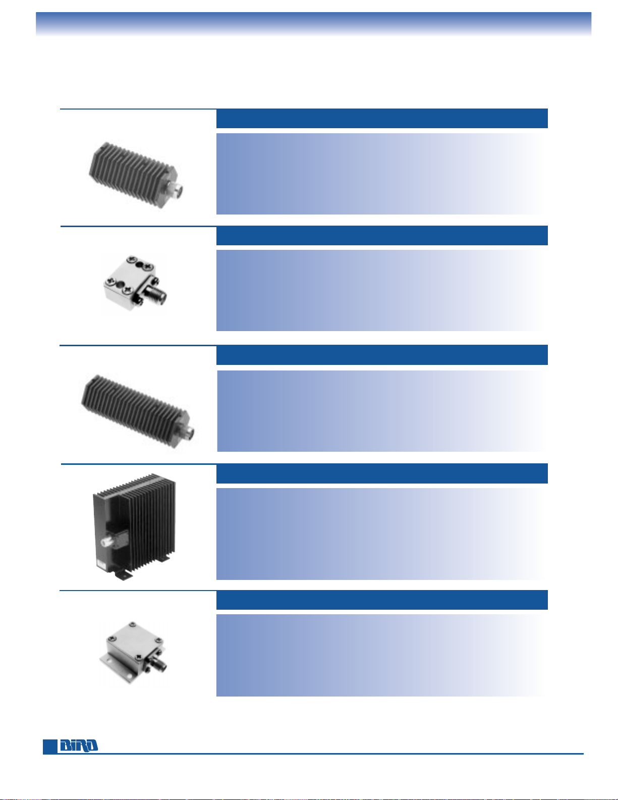
Phone: 440-248-1200 • Fax: 440-248-5426
TERMALINE
RF COAXIAL TERMINATIONS
®
Dry- and Oil-Dielectric Loads
44
Power Rating:
75 W max. @ 40°C
90 W max. @ 25°C
Connectors: BNC, N, TNC, IEC 7/16
Frequency Range and VSWR:
DC to 1 GHz at 1.10:1 max.
1 GHz to 2.4 GHz at 1.25:1 max.
Impedance: 50 ohms, nominal
Ambient Temperature Range: –40°C to +40°C
Operating Position: Any
Coolant: Dry (Convection cooled)
Finish: Black anodized. Silver or Tri-alloy
plated connector
Nominal Size: (with N-type connector):
6.7" L
× 2.3" Dia., (170.2 mm × 58.5 mm)
Weight: 1.575 lbs. (0.72 kg)
75 WATT 75-T SERIES*
50 WATT 50-T SERIES*
Power Rating:
50 W max. @ 40°C
60 W max. @ 25°C
Connectors: BNC, N, TNC
Frequency Range and VSWR:
DC to 1 GHz at 1.10:1 max.
1 GHz to 4 GHz at 1.25:1 max.
Impedance: 50 ohms, nominal
Ambient Temperature Range: –40°C to +40°C
Operating Position: Any
Coolant: Dry (Convection cooled)
Finish: Black anodized. Silver or Tri-alloy
plated connector
Nominal Size: (with N-type connector):
4.7" L
× 2.3" Dia., (119.4 mm × 58.5 mm)
Weight: 1.13 lb. (0.52 kg)
50 WATT 50-CT-FA, 50-CT-MA
Power Rating:**50 W max. @ 100°C flange
temperature, derated to 0 W @ 150°C
Frequency Range and VSWR: DC to 3 GHz at
1.15:1 max. 3 GHz to 6 GHz at 1.25:1 max.
Connectors: SMA
Coolant: Dry (Conduction cooled)
Operating Position: Any
Impedance: 50 ohms, nominal
Finish: Silver or Tri-alloy plated
Nominal Size (includes connector):
0.86" L
× 0.75" W × 0.39" H,
(21.9 mm
× 19.2 mm × 10.0 mm)
Base to Connector Center: 0.162"(4.12 mm)
Mounting Centers: 0.52" (13.3 mm)
Weight: 1.1 oz.. (31.2 g)
NEW
Power Rating: 100 W max. @ 40°C
120 W max. @ 25°C
Connectors: BNC, IEC 7/16, N, TNC
Frequency Range and VSWR:
DC to 1 GHz at 1.10:1 max.
1 GHz to 2.4 GHz at 1.25:1 max.
Impedance: 50 ohms, nominal
Ambient Temperature Range: –40°C to +40°C
Operating Position: Vertical
Coolant: Dry (Convection cooled)
Finish: Black semigloss paint per federal
standard 595. Silver or Tri-alloy
plated connector
Nominal Size: (with N-type connector):
6
13
⁄32" H × 21⁄4" W × 613⁄16" D,
(162.6 mm
× 66.1 mm × 172.8 mm)
Weight: 3.6 lbs. (1.64 kg)
100 WATT 100-T SERIES*
Power Rating:**100 W max. @ 100°C flange
temperature, derated to 0 W @ 150°C
Frequency Range and VSWR: DC to 2 GHz at
1.15:1 max. 2 GHz to 3 GHz at 1.25:1 max.
Connectors: SMA
Coolant: Dry (Conduction cooled)
Operating Position: Any
Impedance: 50 ohms, nominal
Finish: Silver or Tri-alloy plated
Nominal Size (includes connector):
1.34" L
× 1.375" W × 0.56" H,
(34.1 mm
× 35.0 mm × 14.3 mm)
Base to Connector Center: 0.26" (6.6 mm)
Mounting Centers: 0.625" × 1.125"
(15.9 mm
× 28.6 mm)
Weight: 1.0 oz. (28.4 g)
100 WATT 100-CT-FA, 100-CT-MA
NEW
NEW
NEW
* See page 42 for a Model Number Definition that instructs you how to order the correct part.
** When mounted to a suitable heatsink capable of maintaining a 100°C flange temperature.
Page 45
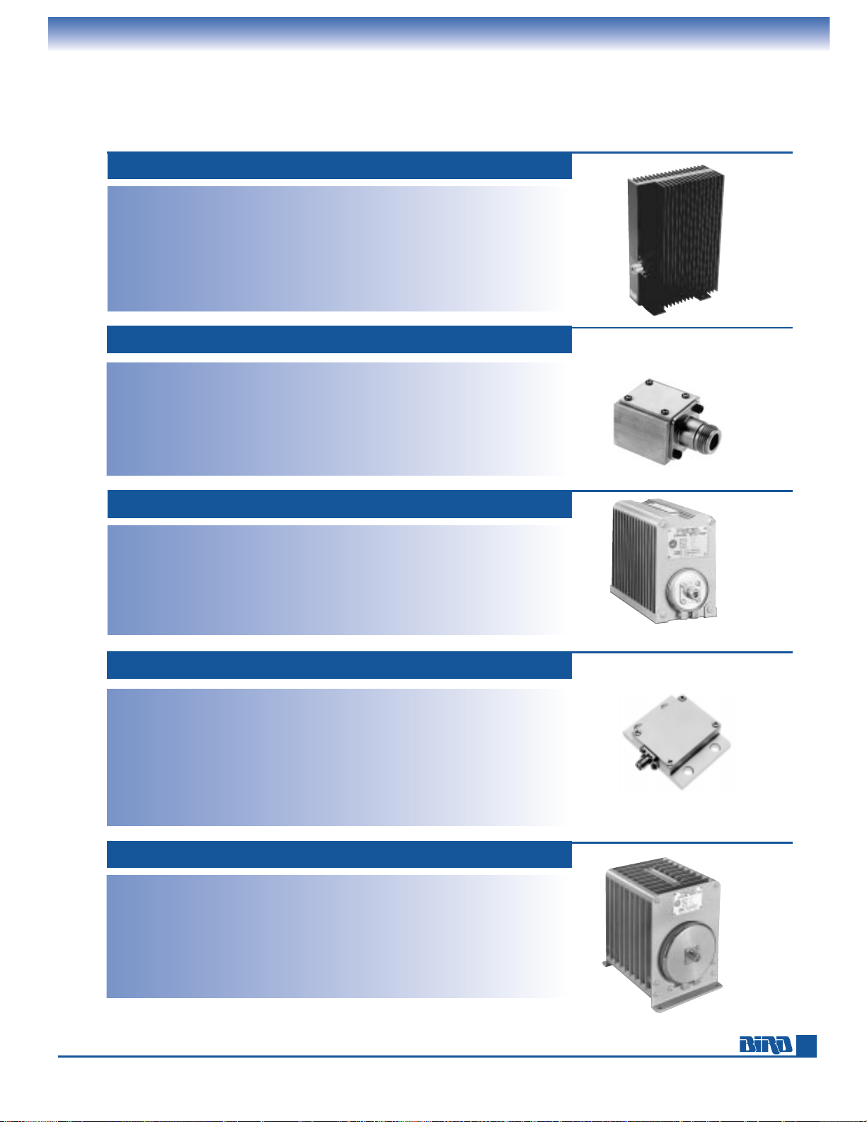
E-mail: [email protected] • Internet: www.bird-electronic.com
Power Rating:**150 W max @ 100°C flange
temperature, derated to 0 W @150°C
Frequency Range and VSWR: DC to 1 GHz at
1.10:1 max. 1 GHz to 2.4 GHz at 1.25:1 max.
Connectors: N, BNC, TNC, SMA
Coolant: Dry (conduction cooled)
Operating Position: Any
Impedance: 50 ohms, nominal
Finish: Silver or Tri-alloy plated
Nominal Size (with N connector):
1.86" L
× 1.25" W × 1.062" H,
(47.3 mm
× 31.8 mm × 27.0 mm)
Base to Connector Center: 0.531" (13.5 mm)
Mounting Centers: 0.575" × 0.825"
(14.6 mm
× 21.0 mm)
Weight (with N connector): 2.2 oz. (62.5 g)
150 WATT 150-CT SERIES*
150 WATT MODEL 8135
Power Rating: 150 W continuous
Frequency Range and VSWR:
DC to 1 GHz at 1.1 max.
1 to 2.5 GHz at 1.2 max.
2.5 to 4 GHz at 1.3 max.
Ambient Temperature Range: –40˚C to +45˚C
Connector: QC type
(Female N normally supplied)
Load Coolant: 0.1 gal. (380 ml) refined
mineral oil
Operating Position: Horizontal only
Finish: Gray powder coat
Nominal Size: (includes connector)
9
1
⁄2" L × 611⁄32" H × 315⁄16" W
(241 mm
× 161 mm × 100 mm)
Weight: 6 lbs. (2.7 kg)
250 WATT MODEL 8141
Power Rating: 250 W continuous
Frequency Range and VSWR:
DC to 1 GHz at 1.1 max.
1 to 1.8 GHz at 1.2 max.
1.8 to 2.5 GHz at 1.3 max.
Ambient Temperature Range:
–40˚C to +45˚C
Connector: QC type
(Female N normally supplied)
Load Coolant: 0.35 gal. (1.3 liters)
silicone oil
Operating Position: Horizontal only
Finish: Gray powder coat
Nominal Size: (includes connectors)
9
9
⁄16" L × 81⁄2" H × 515⁄16" W
(243 mm
× 216 mm × 151 mm)
Weight: 10 lbs. (4.5 kg)
TERMALINE
®
RF COAXIAL TERMINATIONS
Dry- and Oil-Dielectric Loads
Power Rating: 150 W max @ 40°C
180 W max @ 25°C
Connectors: N, TNC, BNC, IEC 7/16
Frequency Range and VSWR:
DC to 1 GHz at 1.10:1 max.
1 GHZ to 2.4 GHz at 1.25:1 max.
Impedance: 50 ohms, nominal
Ambient Temperature Range:
–40°C to +40°C
Operating Position: Vertical
Coolant: Dry (convection cooled)
Finish: Black semigloss paint per federal
standard 595. Silver or Tri-alloy
plated connector
Nominal Size: (with N-type connector):
11
15
⁄16" H × 25⁄8" W × 613⁄16" D,
(302 mm
× 66 mm × 173 mm)
Weight: 6.0 lbs. (2.73 kg.)
150 WATT 150-T SERIES*
NEW
45
250 WATT 250-CT SERIES*
Power Rating:**250 W max. @ 100°C flange
temperature, derated to 0 W @ 150°C
Frequency Range and VSWR:
SMA:
DC to 2 MHz at 1.15:1 max.
2 MHz to 3 MHz @ 1.25:1 max.
All Others: DC to 1 MHz @ 1.15:1 max.
1 MHz to 2.4 MHz @ 1.25:1 max.
Connectors: N, BNC, TNC, SMA
Coolant: Dry (conduction cooled)
Operating Position: Any
Impedance: 50 ohms, nominal
Finish: Silver or tri-alloy plated
Nominal Size (with N connector):
2.36" L
× 2.00" W × 1.062" H,
(60.0 mm
× 50.8 mm × 27.0 mm)
Base to Connector Center: SMA: 0.26"
(6.6 mm)
N: 0.515" (13.1 mm)
Mounting Centers: 0.875" × 1.625" (22.3 mm
× 41.3 mm)
Weight: (with N connector): 5.2 oz. (147.6 g)
NEW
Note: Model 250-CT-FA shown; 250-CT-FN
is identical in appearance to 500-CT-FN
* See page 42 for a Model Number Definition that instructs you how to order the correct part.
** When mounted to a suitable heatsink capable of maintaining a 100°C flange temperature.
Page 46
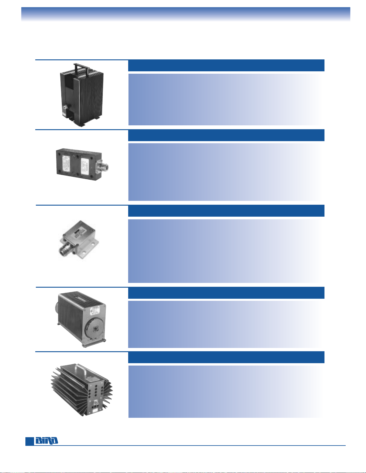
Phone: 440-248-1200 • Fax: 440-248-5426
600 WATT (DRY) MODEL 8431
Power Rating:
600 W continuous, vertical
500 W continuous, horizontal
Connectors: SQC Type
(Female N normally supplied)
Frequency Range and VSWR:
DC to 1 GHz at 1.10:1 max.
1 GHz to 2.5 GHz at 1.25:1 max.
Impedance: 50 ohms, nominal
Ambient Temperature Range:
–40°C to +45°C
Operating Position: Horizontal or vertical
Coolant: Dry (Convection cooled)
Finish: Black powder coat with anodized fins.
Nominal Size: (with N-type connector):
9
5
⁄16" H × 81⁄2" W ×135⁄16" D,
(235 mm
× 216 mm × 336 mm)
Weight: 13 lbs (5.91 kg.)
TERMALINE
®
RF COAXIAL TERMINATIONS
Dry- and Oil-Dielectric Loads
500 WATT MODEL 8201
Power Rating: 500 W continuous
Frequency Range and VSWR:
DC to 1 GHz at 1.1 max.
1 to 2.5 GHz at 1.25 max.
Ambient Temperature Range:
–40˚C to +45˚C
Connector: QC type
(Female N normally supplied)
Load Coolant: 0.9 gal. (3.42 liters) refined
mineral oil
Operating Position: Horizontal only
Finish: Gray powder coat
Nominal Size: (includes connectors)
16
13
⁄16" L × 81⁄2" H × 515⁄16" W
(427 mm
× 216 mm × 151 mm)
Weight: 21 lbs. (9.5 kg)
Power Rating: 300 W max @ 40°C
360 W max @ 25°C
Connectors: N, TNC, BNC, IEC 7/16
Frequency Range and VSWR:
DC to 1 GHz at 1.10:1 max.
1 GHZ to 2.4 GHz at 1.25:1 max.
Impedance: 50 ohms, nominal
Ambient Temperature Range:
–40°C to +40°C
Operating Position: Vertical
Coolant: Dry (convection cooled)
Finish: Black semigloss paint per federal
standard 595. Silver or Tri-alloy
plated connector
Nominal Size: (with N-type connector):
10
15
⁄16" H × 513⁄32" W × 613⁄16" D,
(276.9 mm
× 137.2 mm × 172.8 mm)
Weight: 11.5 lbs. (5.23 kg.)
300 WATT 300-T SERIES*
Power Rating: 300 W continuous when
attached to suitable heat sink
Connectors: N Female normally supplied
Frequency Range and VSWR:
DC to 800 MHz at 1.10:1 max.
800 to 1500 MHz at 1.20:1 max.
1500 to 2500 MHz at 1.30:1 max.
Impedance: 50 ohms, nominal
Ambient Temperature Range: –40°C to +45°C
Heat Sink Required: 800 Sq. Inch Plate ×1⁄8"
or equivalent (5200 cm
2
× 3 mm)
Operating Position: Any
Coolant: Dry (conduction cooled)
Finish: Silver or Tri-alloy
Silver-plated or Tri-alloy connectors
Nominal Size: (with N-type connector):
4
25
⁄64" L × 2" W × 11⁄32" H
(110 mm
× 51 mm × 26 mm)
Weight: 12 oz. (340 g.)
300 WATT MODEL 8072A-1
46
500 WATT 500-CT SERIES*
Power Rating:**500 W max. @ 100°C flange
temperature, derated to 0 W @ 150°C
Frequency Range and VSWR:
DC to 1 GHz at 1.10:1 max.
Connector: N, BNC, TNC, SMA, or IEC 7/16
Coolant: Dry (conduction cooled)
Operating Position: Any
Impedance: 50 ohms, nominal
Finish: Silver or tri-alloy plated
Nominal Size (includes connector):
N: 2.36" L × 2.00" W ×1.062" H,
(60.0 mm
× 50.8 mm × 27.0 mm)
IEC 7/16: 2.80" L × 2.00" W × 1.20" H,
(71.2 mm
× 50.8 mm × 30.5 mm)
Base to Connector Center: N: 0.515"
(13.1 mm)
IEC 7/16: 0.675" (17.2 mm)
Mounting Centers: 0.875" × 1.625"
(22.3 mm
× 41.3 mm)
Weight: N: 8.2 oz. (232.9 g)
IEC 7/16: 6.0 oz. ( 170.3 g)
NEW
* See page 42 for a Model Number Definition that instructs you how to order the correct part.
** When mounted to a suitable heatsink capable of maintaining a 100°C flange temperature.
Page 47
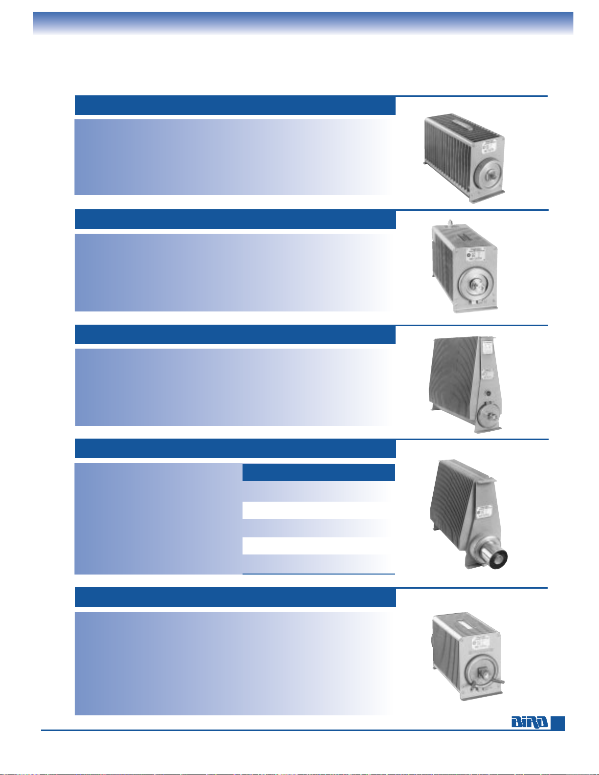
E-mail: [email protected] • Internet: www.bird-electronic.com
TERMALINE
®
RF COAXIAL TERMINATIONS
Oil-Dielectric, Convection, and Water Cooled
1 kW MODEL 8251
Power Rating: 1000 W continuous
Frequency Range and VSWR:
DC to 1 GHz at 1.1 max.
1 to 2 GHz at 1.25 max.
2 to 2.4 GHz at 1.3 max.
Ambient Temperature Range: –40˚C to +45˚C
Connector: QC type (Female LC normally sup-
plied and Female N supplied unmounted)
Load Coolant: 1.1 gal. (4.1 liters) silicon oil
Operating Position: Horizontal only
Finish: Gray powder coat
Nominal Size: (includes connectors)
17
29
⁄32" L × 81⁄2" H × 515⁄16" W
(455 mm
× 216 mm × 151 mm)
Weight: 25 lbs., 8 oz. (11.5 kg)
1 kW MODEL 8833-300
Power Rating: 1000 W continuous
Frequency Range and VSWR:
DC to 1 GHz at 1.1 max.
1 to 2.5 GHz at 1.25 max.
Ambient Temperature Range: –40˚C to +45˚C
Connector: QC type (Female LC normally sup-
plied) Female N supplied unmounted
Load Coolant: 2.9 gal. (11 liters) refined
mineral oil
Operating Position: Horizontal only
Finish: Gray powder coat
Nominal Size: (with connectors)
23
1
⁄8" L × 173⁄16" H × 71⁄8" W
(587 mm
× 437 mm × 181 mm)
Weight: 54 lbs., 10 oz. (24.8 kg)
1.5 kW MODEL 8860 SERIES
Power Rating: 1500 W continuous
Frequency Range and VSWR:
DC to 1 GHz at 1.1 max.
1 to 2.0 GHz at 1.25 max.
Ambient Temperature Range: –40˚C to +45˚C
Load Coolant: 1.5 gal. (5.68 liters) silicone oil
Operating Position: Horizontal only
Finish: Gray powder coat
Nominal Size: 71⁄2"W × 131⁄8"H
(184 mm
× 333 mm)
OVERALL
MODEL CONNECTOR
LENGTH
WEIGHT
8860 QC-LC(F) 171⁄8" 30 lbs.
(445 mm) (13.6 kg)
8861 1
5
⁄8" Unflg. 177⁄8" 31 lbs.
(454 mm) (14.1 kg)
8862 1
5
⁄8" EIA flg. 171⁄8" 31 lbs.
(445 mm) (14.1 kg)
8863 3
1
⁄8" Unflg. 185⁄8" 32 lbs.
(473 mm) (14.5 kg)
8864 3
1
⁄8" EIA flg. 191⁄2" 32 lbs.
(495 mm) (14.5 kg)
2.5 kW (WATER COOLED) MODEL 8230
Power Rating: With cooling water: 2500 W
Without cooling water: 200 W in vertical
position, 500 W in horizontal position
Frequency Range and VSWR:
DC to 1 GHz at 1.1 max.
1 to 2.5 GHz at 1.25 max.
Ambient Temperature Range: –40˚C to +45˚C
Water Temperature Range: +8˚C to +80˚C
Water Flow Rate: 1/2 gal./minute
(2 liters/minute) min.
Connector: QC type (Female LC normally
supplied)
Load Coolant: 0.9 gal. (3.4 liters) refined
mineral oil
Operating Position: Vertical, connector
down (when water cooled)
Finish: Gray powder coat
Nominal Size: (with connectors)
17
23
⁄32" L × 81⁄2" H × 515⁄16" W
(450 mm
× 216 mm × 151 mm)
Weight: 27 lbs. (12 kg)
600 WATT MODEL 8401
Power Rating: 600 W continuous
Frequency Range and VSWR:
DC to 1 GHz at 1.1 max.
1 to 2.8 GHz at 1.2 max.
2.8 to 3 GHz at 1.3 max.
Ambient Temperature Range: –40˚C to +45˚C
Connector: QC type
(Female N normally supplied)
Load Coolant: 0.7 gal. (2.65 liters) refined
mineral oil
Operating Position: Horizontal only
Finish: Gray powder coat
Nominal Size: (with connectors)
16
13
⁄16" H × 81⁄2" W × 515⁄16" D,
(427 mm
× 216 mm × 151 mm)
Weight: 20 lbs. (9.1 kg)
47
Page 48
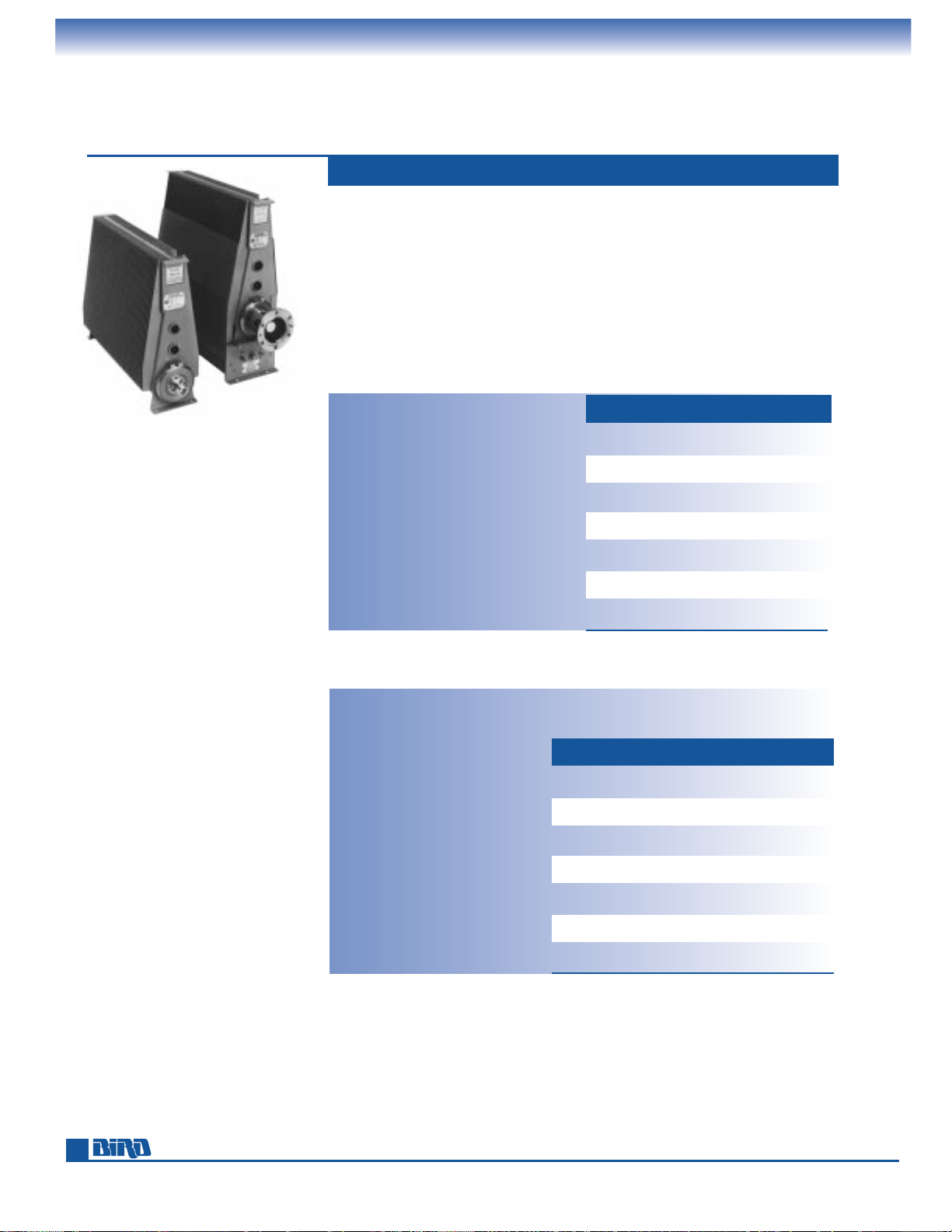
Phone: 440-248-1200 • Fax: 440-248-5426
TERMALINE
®
RF COAXIAL TERMINATIONS
Oil-Dielectric Loads
The 8890 Series is rated at 2.5 kW with convection cooling or 5 kW with the BA-300
forced-air cooling option. Both configurations can be ordered with an optional
Overload Thermoswitch (P/N 8890-008) or with two thermoswitches for “standby
service” as a reject load for dual transmitter systems.
With dual thermoswitches, one normally open switch closes to activate the blower
when power is applied to the load and coolant temperature rises, as when one
transmitter fails. The second normally closed switch, is an over-temperature interlock safety switch. For completely assembled and wired dual thermoswitch units,
order 8890/91/92/95/97/98-315 for 115 Vac, 50/60 Hz units, or 8890/91/92/95/97/
98-320 for 230 Vac, 50/60 Hz units.
2.5 kW AND 5 kW 8890 SERIES
Power Rating: 2500 W continuous
Frequency Range and VSWR:
DC to 1 GHz at 1.1 max.
1 to 2 GHz at 1.25 max.
2 to 2.4 GHz at 1.3 max.
Impedance: 50 ohms nominal
(8896-300 51.5 ohms nominal)
Ambient Temperature Range: –40˚C to +45˚C
Load Coolant: 2.9 gal. (11 liters) silicon oil
Operating Position: Horizontal only
Finish: Gray powder coat
Nominal Size: 7" W × 173⁄16" H
(178 mm
× 547 mm). See table for length.
MODEL 8890-300 (left)
MODEL 8891-300 (right)
with BA-300-115
2.5 kW 8890-300 SERIES
NOTE: Overload thermoswitch P/N 8890-008 is optional. Free assembly when ordered as a package.
*** Specify –115 for 115 Vac Blower or –230 for 230 Vac blower.
NOTE: Overload thermoswitch P/N 8890-008 is optional. Free assembly when ordered as a package.
RECESS OVERALL
MODEL CONNECTOR
(IN.) LENGTH
WEIGHT
8890-300 QC-LC(F) — 231⁄8" 57 lbs.
(587 mm) (26 kg)
8892-300 1
5
⁄8" EIA Flg. 0.625 231⁄8" 58 lbs.
(587 mm) (26 kg)
8895-300 1
5
⁄8" Unflg. 0.438 223⁄16" 58 lbs.
(564 mm) (26 kg)
8891-300 3
1
⁄8" EIA Flg. 0.922 251⁄8" 59 lbs.
(638 mm) (27 kg)
8896-300 3
1
⁄8" Unflg. 0.0 245⁄32" 59 lbs.
(51.5 Ω) (626 mm) (27 kg)
8897-300 3
1
⁄8" Unflg. 0.0 245⁄32" 59 lbs.
(626 mm) (27 kg)
8898-300 3
1
⁄8" Unflg. 0.688 245⁄32" 59 lbs.
(636 mm) (27 kg)
Power Rating: 5000 W continuous
with blower on, 1250 W with
blower off
Frequency Range and VSWR:
DC to 1 GHz at 1.1 max.
1 to 2 GHz at 1.25 max.
2 to 2.4 GHz at 1.3 max.
Impedance: 50 ohms nominal
(8896-300 51.5 ohms nominal)
Ambient Temperature Range:
–40˚C to +45˚C
Load Coolant: 2.9 gal. (11 liters)
silicone oil
Operating Position: Horizontal only
Finish: Gray powder coat
Nominal Size: 73⁄8" W × 2211⁄16" H
(187 mm
× 560 mm). See table
for length.
Blower AC Power:
5 kW 8890-300 SERIES WITH BA-300-115, -230
RECESS OVERALL
MODEL CONNECTOR
(IN.) LENGTH
WEIGHT
8890-300 QC-LC(F) — 231⁄8" 70 lbs.
with BA-300*** (587 mm) (32 kg)
8892-300 1
5
⁄8" EIA Flg. 0.625 231⁄8" 72 lbs.
with BA-300*** (587 mm) (33 kg)
8895-300 1
5
⁄8" Unflg. 0.438 223⁄16" 72 lbs.
with BA-300*** (564 mm) (33 kg)
8891-300 3
1
⁄8" EIA Flg. 0.922 251⁄8" 73 lbs.
with BA-300*** (638 mm) (33 kg)
8896-300 3
1
⁄8" Unflg. 0.0 245⁄32" 73 lbs.
with BA-300*** (614 mm) (33 kg)
8897-300 3
1
⁄8" Unflg. 0.0 245⁄32" 73 lbs.
with BA-300*** (614 mm) (33 kg)
8898-300 3
1
⁄8" Unflg. 0.688 245⁄32" 73 lbs.
with BA-300*** (614 mm) (33 kg)
Model BA-300-115: 115 Vac, 50/60 Hz, 0.6 A
Model BA-300-230: 230 Vac, 50/60 Hz, 0.3 A
Bird oil-dielectric load resistors have never been and are not now manufactured with
Poly Chlorinated Biphenyls (PCBs).
48
Page 49
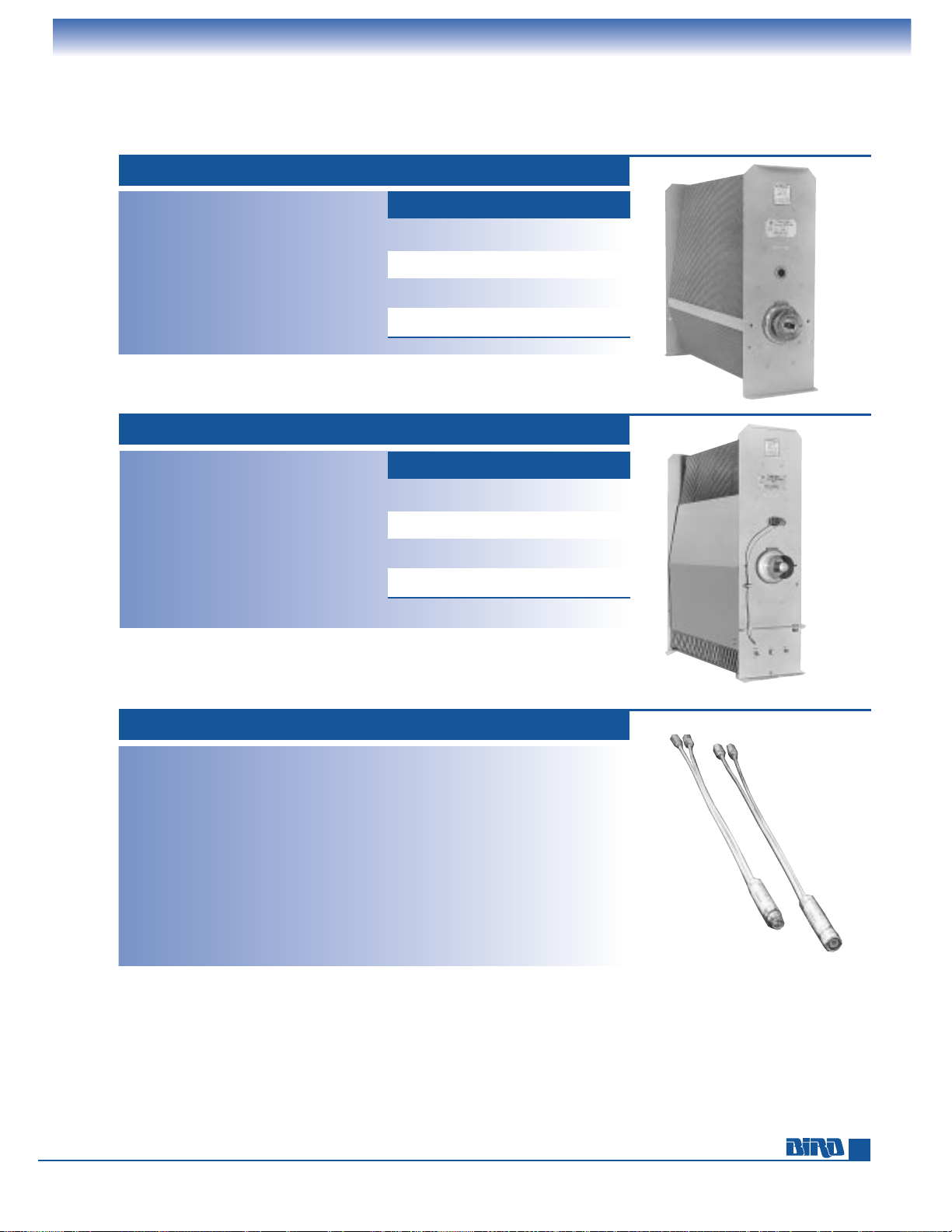
E-mail: [email protected] • Internet: www.bird-electronic.com
TERMALINE
®
RF COAXIAL TERMINATIONS
Oil-Dielectric, Direct Water-Cooled Loads
5 kW OIL DIELECTRIC 8921 SERIES
Power Rating: 5000 W continuous
Frequency Range and VSWR:
DC to 1 GHz at 1.1 max.
Ambient Temperature Range: –40˚C to +45˚C
Load Coolant: 62⁄3gals. (25.3 liters)
silicone oil
Operating Position: Horizontal only
Finish: Gray powder coat
Nominal Size: 91⁄2" W × 2513⁄16" H
(241 mm
× 656 mm). See table for length.
NOTE: An 8890-008 over-temperature interlock safety switch is included.
OVERALL
MODEL CONNECTOR
LENGTH
WEIGHT
8921 QC-LC(F) 3027⁄32" 119 lbs.
(783 mm) (54 kg)
8922 1
5
⁄8" EIA flg. 3027⁄32" 121 lbs.
(783 mm) (55 kg)
8926 3
1
⁄8" EIA flg. 323⁄4" 126.5 lbs.
(832 mm) (57 kg)
8927 3
1
⁄8" Unflg. 317⁄8" 126 lbs.
(809 mm) (57 kg)
10 kW OIL DIELECTRIC 8931–115, –230 SERIES
Power Rating: 10 kW continuous
Frequency Range: and VSWR:
DC to 400 MHz at 1.15 max.
400 MHz to 1 GHz at 1.20 max.
Ambient Temperature Range: –40˚C to +45˚C
Load Coolant: 62⁄3gals. (25.3 liters)
silicone oil
Operating Position: Horizontal only
Finish: Gray powder coat
Nominal Size: 91⁄2" W × 335⁄16" H
(241 mm
× 821 mm). See table for length.
NOTE: Both an 8892-333 blower control switch and an 8890-017 over-temperature interlock safety switch
are included.
*** AC power 115 or 230 Vac, 50/60 Hz (add suffix –115 or –230 to Model number)
OVERALL
MODEL CONNECTOR
LENGTH
WEIGHT
8931-*** QC-LC(F) 307⁄32" 135 lbs.
(768 mm) (61 kg)
8932-*** 1
5
⁄8" EIA flg. 307⁄32" 137 lbs.
(768 mm) (62 kg)
8936-*** 3
1
⁄8" EIA flg. 321⁄8" 142.5 lbs.
(816 mm) (64.8 kg)
8937-*** 3
1
⁄8" Unflg. 311⁄4" 142 lbs.
(793 mm) (64.5 kg)
1 kW DIRECT WATER COOLED 8710 SERIES
Power Rating: 1000 W continuous
Frequency Range and VSWR:
DC to 1 GHz at 1.10 max.
1 to 3 GHz at 1.3 max.
3 to 3.5 GHz at 1.35 max.
Water Temperature Range:
+
8˚C to +80˚C
Water Flow Rate: 1 quart/minute @ 8°C to
3qpm @ 80°C (0.95 liters/minute @ 8°C
to 2.84 lpm @ 80°C )
Connectors: Waterlines 1⁄8" FPT
Model 8710F (N Female)
Model 8710M (N Male)
Model 8711F (C Female)
Model 8711M (C Male)
Model 8713
7
⁄8" EIA Flg.
Load Coolant: Potable water
Operating Position: Any
Finish: Silver plated
Nominal Size: (excl. 18" waterlines)
3
21
⁄32" ×11⁄16" Dia., (93 mm × 17 mm)
Weight: Models 8710, 8711 5 oz. (142 g),
Model 8713 14 oz. (397 g)
MODEL 8711 (LEFT)
MODEL 8710 (RIGHT)
Bird oil-dielectric load resistors have never been and are not now manufactured with
Poly Chlorinated Biphenyls (PCBs).
49
Page 50
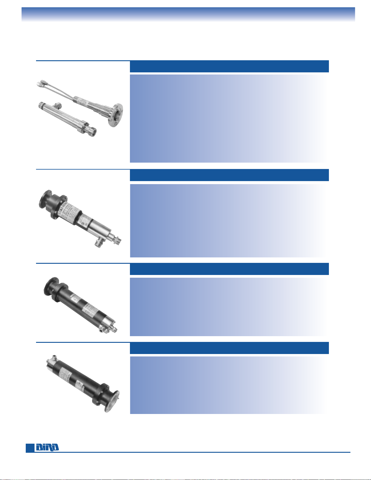
Phone: 440-248-1200 • Fax: 440-248-5426
TERMALINE
®
RF COAXIAL TERMINATIONS
Direct Water-Cooled Loads
5 kW DIRECT WATER COOLED MODELS 8720, 8726
Power Rating: 5 kW continuous
Frequency Range and VSWR:
Model 8720: DC to 500 MHz 1.1 max.,
500 to 900 MHz 1.15 max.,
900 to 2000 MHz 1.25 max.
Model 8726: DC to 500 MHz 1.1 max.,
500 to 2000 MHz 1.25 max.
Water Temperature Range:
+
5˚C to +80˚C
Water Flow Rate: 1 gal./minute @ 5°C to
4gpm @ 80°C (3.8 liters/minute @ 5°C to
15.21 lpm @ 80°C)
Connectors: Waterlines 1⁄2" FPT (8720) or
3
⁄4" hose (8726)
Model 8720 1
5
⁄8" EIA Flg.
Model 8726 QC type
(Female LC normally supplied)
Load Coolant: Potable water
Operating Position: Any
Finish: Bright nickel plated
Nominal Size: (excl. 8" waterlines)
Model 8720, 8
1
⁄32" × 15⁄8" Dia.,
(204 mm
× 41 mm). Input Flg. 31⁄2" Dia.
Model 8726, 8
7
⁄8" × 15⁄8" Dia.,
(225
× 41 mm)
Weight: Model 8720: 2 lbs. (900 g)
Model 8726: 2
1
⁄2lbs. (1.1 kg)
10 kW ECONOLOAD
®
MODELS 8730A, 8731, 8738A
Power Rating: 10 kW continuous
Frequency Range and VSWR:
Model 8731,
1.1 max. 1 kHz to 1 GHz
(DC for continuity checks)
Models 8730A and 8738A, 1.1 max.
DC to 1 GHz
Water Temperature Range:
+
5˚C to +60˚C
Water Flow Rate: 4 gals./minute @ 5°C to
6 gpm @60°C (15.2 liters/minute @ 5°C
to 22.8 lpm @ 60°C)
Connectors: Waterlines 1⁄2" FPT or 3⁄4" hose
Model 8730A, 1
5
⁄8" EIA Flg.
Model 8731, 3
1
⁄8" EIA Flg.
Model 8738A, 3
1
⁄8" Unflg. (Flush)
Load Coolant: Potable water
Operating Position: Any
Finish: Black powder coat
Nominal Size: 143⁄4" × 23⁄4" Dia.,
(375 mm
× 70 mm). Input Flg.
Model 8730, 3
1
⁄2" Dia., (89 mm),
Model 8731, 5
3
⁄16" Dia., (132 mm)
Weight: Model 8730 7 lbs. 14 oz. (3.6 kg),
Model 8731 6 lbs. 10 oz. (3 kg),
8738 6 lbs. (2.8 kg)
MODEL 8720 (top)
MODEL 8726 (bottom)
20 kW ECONOLOAD
®
MODELS 8745, 8746
Power Rating: 20 kW continuous
Frequency Range and VSWR: 1.1 max. 1 kHz
to 900 MHz (DC for continuity checks)
Water Temperature Range:
+
5˚C to +60˚
Water Flow Rate: 6 gal./minute @ 5°C to
8 gpm @ 60°C (22.8 liters/minute @ 5°C
to 30.4 lpm @ 60°C)
Connector: Waterlines 1⁄2" FPT or 3⁄4" hose
Model 8745 3
1
⁄8" EIA Flg.
Model 8746 3
1
⁄8" Unflg. (Flush)
Load Coolant: Potable water
Operating Position: Any
Finish: Black powder coat
Nominal Size: 191⁄2" × 31⁄2" Dia.,
(495 mm
× 90 mm),
Input Flg. 5
3
⁄16" Dia. (132 mm)
Weight: Model 8745 15 lbs. 13 oz. (7.2 kg),
Model 8746 15 lbs. 5 oz. (7.0 kg)
30 kW ECONOLOAD
®
MODELS 8755, 8756
Power Rating: 30 kW continuous
Frequency Range and VSWR: 1.1 max. 1 kHz
to 900 MHz (DC for continuity checks)
Water Temperature Range:
+
5˚C to +60˚C
Water Flow Rate: 7 gal./minute @ 5°C to 9
gal./minute @ 60°C (26.6 liters/minute @
5°C to 34.2 lpm @ 60°C)
Connectors: Waterlines 1⁄2" FPT or 3⁄4" hose
Model 8755 3
1
⁄8" EIA Flg.
Model 8756 3
1
⁄8" Unflg. (Flush)
Load Coolant: Potable water
Operating Position: Any
Finish: Black powder coat
Nominal Size: 191⁄2" x 31⁄2" Dia.,
(495 mm
× 90 mm).
Input Flg. 5
3
⁄16" Dia. (132 mm)
Weight: Model 8755 15 lbs. 13 oz. (7.2 kg),
Model 8756 15 lbs. 5 oz. (7.0 kg)
See page 53 for load accessories such as coupling kits, dollies, etc.
50
Page 51
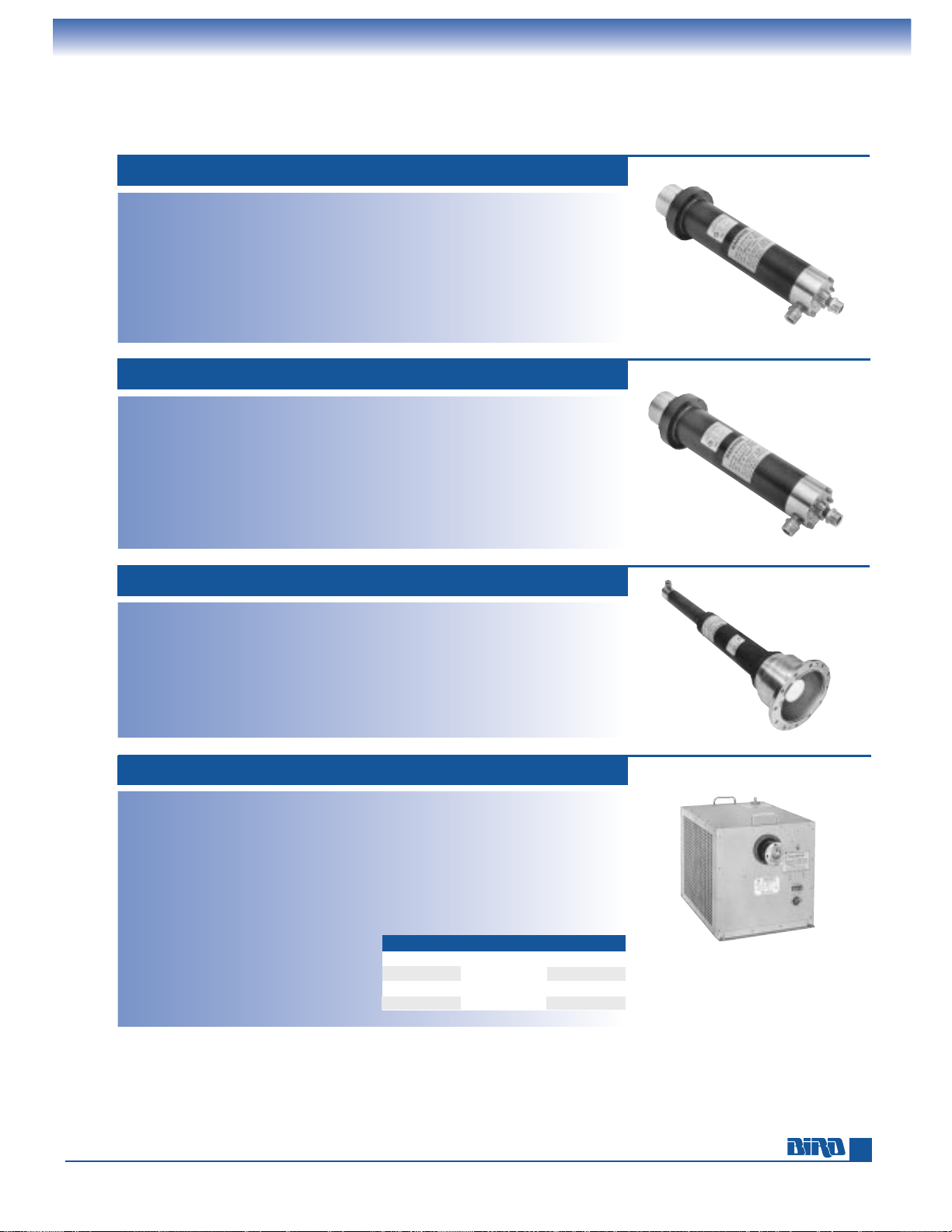
E-mail: [email protected] • Internet: www.bird-electronic.com
TERMALINE
®
RF COAXIAL TERMINATIONS
Direct Water-Cooled Loads, MODULOAD®Systems
40 kW ECONOLOAD
®
MODELS 8765, 8766
Power Rating: 40 kW continuous
Frequency Range and VSWR: 1.1 max. 1 kHz
to 900 MHz (DC for continuity checks)
Water Temperature Range:
+
5˚C to +60˚C
Water Flow Rate: 8 gals./minute @ 5°C to
10 gpm @ 60 °C (30.4 liters/minute @
5°C to 3.8 lpm @ 60°C)
Connectors: Waterlines 1⁄2" FPT or 3⁄4" hose
Model 8765 3
1
⁄8" EIA Flg.
Model 8766 3
1
⁄8" Unflg. (Flush)
Load Coolant: Potable water
Operating Position: Any
Finish: Black powder coat
Nominal Size: 191⁄2" × 31⁄2" Dia.,
(495 mm
× 90 mm),
Input Flg. 5
13
⁄16" Dia. (132 mm)
Weight: Model 8765 15 lbs. 13 oz. (7.2 kg),
Model 8766 15 lbs. 5 oz. (7.0 kg)
50 kW ECONOLOAD
®
MODELS 8775, 8776
Power Rating: 50 kW continuous
Frequency Range and VSWR: 1.1 max. 1 kHz
to 900 MHz (DC for continuity checks)
Water Temperature Range:
+
5˚C to +60˚C
Water Flow Rate: 9 gals./minute @ 5°C to
11 gpm @ 60°C (34.2 liters/minute @
5°C to 41.8 lpm @ 60°C)
Connectors: Waterlines 1⁄2" FPT or 3⁄4" hose
Model 8775 3
1
⁄8" EIA Flg.
Model 8776 3
1
⁄8" Unflg. (Flush)
Load Coolant: Potable water
Operating Position: Any
Finish: Black powder coat
Nominal Size: 191⁄2" × 31⁄2" Dia.,
(495 mm
× 90 mm),
Input Flg. 5
3
⁄16" Dia., (132 mm)
Weight: Model 8775 15 lbs. 13 oz. (7.2 kg),
Model 8776 15 lbs. 5 oz. (7.0 kg)
80 kW ECONOLOAD
®
MODEL 8792
Power Rating: 80 kW continuous
Frequency Range and VSWR: 1.15 max. 1 kHz
to 800 MHz (DC for continuity checks)
Water Temperature Range:
+
5˚C to +60˚C
Water Flow Rate: 9 gals./minute @ 5°C to
12 gpm @ 60°C (34.2 liters/minute @ 5˚C
to 45.6 lpm @ 60°C
Connector: 61⁄8" EIA Flg.
Load Coolant: Potable water
Operating Position: Any
Finish: Black powder coat
Nominal Size: 34" × 5" Dia.
(864 mm
× 127 mm),
Input Flg. 8
1
⁄8" Dia., (206 mm) add
approximately 1
1
⁄4" (32 mm) to length
for rear water fitting
Weight: 30 lbs. 10 oz. (14 kg)
10 kW MODULOAD
®
MODELS 8631, 8635, 8638
Power Rating: 10 kW continuous
Frequency Range and VSWR: 1.1 max. 1 kHz
to 1000 MHz (DC for continuity checks)
Ambient Temperature Range: (per power
level and coolant mix)
≤10 kW: (35% Ethylene Glycol/65%
Water) +5°C to +45°C
≤10 kW: (35% Ethylene Glycol/65%
Water) –20°C to +35°C
Connector: 8635: 15⁄8" EIA Flg.
8631: 3
1
⁄8" EIA FIg. 8638: 31⁄8" Unflg.
Load Coolant: 10 pts. (4.75 liters) 100% water
or 65% water/35% industrial Ethylene
Glycol. With forced-air cooling
Operation Position: Horizontal only
Finish: Gray powder coat
Nominal Size: (excluding connectors)
22
1
⁄8" L × 1515⁄16" W × 1513⁄16" D,
(562 mm
× 405 mm x 402 mm)
Weight: 110 lbs. (50 kg)
AC Power: 115 V models: 91⁄2A nominal @
115V ±10% 60Hz
230 V models: 4
3
⁄4A nominal @
230V ±10% 50Hz
Optional Dolly: P/N 6771-011
51
Power
115 V 50 Hz
115 V 60 Hz
230 V 50 Hz
230 V 60 Hz
Basic P.N.
8631,8635,
or 8638
Add Suffix
-115-5
-115
-230
-230-6
Page 52
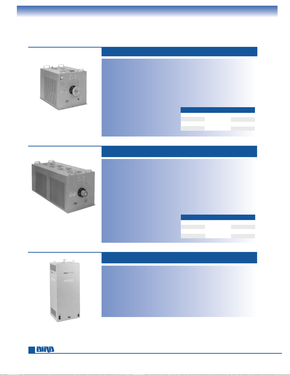
Phone: 440-248-1200 • Fax: 440-248-5426
TERMALINE
®
RF COAXIAL TERMINATIONS
MODULOAD®Systems and Dry, Forced-Air Loads
50 kW MODULOAD®MODELS 8655, 8656
Power Rating: 50 kW continuous
Frequency Range and VSWR: 1.1 max. 1 kHz
to 900 MHz (DC for continuity checks)
Ambient Temperature Range: (per power
level and coolant mix)
≥40 kW: (100% Water) +5°C to +30°C.
<40 kW: (100% Water) +5°C to +45°C.
≥40 kW: (35% Ethylene Glycol/65%
Water) –20°C to +25°C;
<40 kW: (35% Ethylene Glycol/65%
Water) –20°C to +35°C
Connector: 8655: 31⁄8" EIA Flg.
8656: 3
1
⁄8" Unflg. (Flush)
Load Coolant: 17 qts. (16.1 liters) 100%
water or 65% water/35% industrial
ethylene glycol. With forced-air cooling
Operation Position: Horizontal only
Finish: Gray powder coat
Nominal Size: (excluding connectors)
46
1
⁄2" L × 195⁄32" W × 199⁄16" D,
(659 mm
× 487 mm × 497 mm)
Weight: 275 lbs. (125 kg)
AC Power:
115 V models: 14 A nominal @
115 V ±10% 60 Hz
230 V models: 7 A nominal @
230 V ±10% 50 Hz
Optional Dolly: Model 6772-011 on page 53
8655-115-6, 8656-115–6 for 60 Hz
8655-230-5, 8656-230–5 for 50 Hz
10 kW, 15 kW DRY, FORCED-AIR LOAD
MODEL 8578A100
MODEL 8578A150
Power Rating:
Model 8578A100: 10 kW continuous
Model 8578A150: 15 kW continuous
Frequency Range and VSWR:
1.15:1, DC to 108 MHz
Ambient Temperature Range: –40°C to +40°C
Connector: 15⁄8" EIA Flanged (Swivel)
3
1
⁄8" Unflanged option
Load Coolant: Dry (forced air)
Resistors: Tubular type, parallel connection,
50 ohms nominal
Operation Position: Any (except blockage
of air inlets and exhaust)
Finish: Gray powder coat
Nominal Size: (including connectors)
39
7
⁄32" H × 1615⁄32" W × 137⁄16" D,
(996 mm
× 418 mm × 341 mm)
Weight: 70 lbs. (31.8 kg)
AC Power:
115/230 ±10% Vac, 50/60 Hz 8.6 amps max.
@ 115 Vac
See page 53 for load accessories such as coupling kits, dollies, etc.
52
25 kW MODULOAD
®
MODELS 8645, 8646
Power Rating: 25 kW continuous
Frequency Range and VSWR: 1.1 max. 1 kHz
to 900 MHz (DC for continuity checks)
Ambient Temperature Range: (per power
level and coolant mix)
≤25 kW: (100% Water) +5°C to +30°C.
<20 kW: (100% Water) +5°C to +45°C.
≤25 kW: (35% Ethylene Glycol/65%
Water) –20°C to +25°C;
<20 kW: (35% Ethylene Glycol/65%
Water) –20°C to +35°C
Connector: 8645: 31⁄8" EIA Flg. 8646: 31⁄8" Unflg.
Load Coolant: 9 qts. (8.5 liters) 100% water
or 65% water/35% industrial Ethylene
Glycol. With forced-air cooling
Operation Position: Horizontal only
Finish: Gray powder coat
Nominal Size: (excluding connectors)
25
15
⁄16" L × 195⁄32" W × 199⁄16" D,
(659 mm
× 487 mm × 497 mm)
Weight: 155 lbs. (70 kg)
AC Power: 115 V models: 11 A nominal @
115V ±10% 60Hz
230 V models: 5
1
⁄2A nominal @
230V ±10% 50Hz
Optional Dolly: P/N 6771-011
Power
115 V 50 Hz
115 V 60 Hz
230 V 50 Hz
230 V 60 Hz
Basic P.N.
8645 or
8646
Add Suffix
-115-5
-115
-230
-230-6
Power
115 V 50 Hz
115 V 60 Hz
230 V 50 Hz
230 V 60 Hz
Basic P.N.
8655 or
8656
Add Suffix
-115-5
-115-6
-230-5
-230-6
Page 53
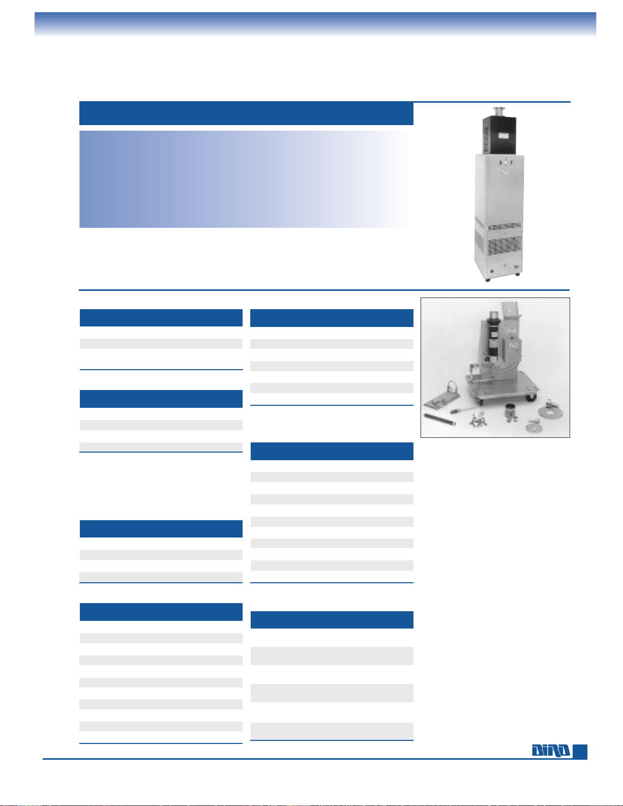
TERMALINE
®
RF COAXIAL TERMINATIONS
25 kW Dry, Forced-Air Load and Termination Accessories
A 6770-125
B 8755-027-4
C 8890-008
D 4600-020
E 5-289
F 4902-025
G 4600-025
MODEL DESCRIPTION
6771-011 For 10 and 25 kW MODULOAD
®
6772-011 For 50 kW MODULOAD
®
****-677-1 For ECONOLOAD®, 115 Vac
****-677-2 For ECONOLOAD
®
, 230 Vac
DOLLIES
MODEL DESCRIPTION
4600-025 31⁄8" Flg. to 15⁄8" EIA Flg. 50 ohms
4712-015 1
5
⁄8" Flg. to 7⁄8" EIA Flg. 50 ohms
4902-025 3
1
⁄8" Flg. to 61⁄8" EIA Flg. 50 ohms
7500-076 DC Connector Plug
FLANGE-TO-FLANGE ADAPTERS
**** Add -677-1 or -677-2 to any ECONLOAD
®
Model No. (10 kW to 80 kW) to get it mounted
on a dolly with a control box, water flow switch
and bracket (for an optional wattmeter).
8776-677-1 shown. –1 = 115 Vac 50/60 Hz,
–2 = 230 Vac 50/60 Hz.
* 51.5 ohm with adapter to 50 ohm
MODEL LINE TYPE OHMS
4240-220
7
⁄8" Flg. 50
4712-020 1
5
⁄8" Flg. 50
4600-020 3
1
⁄8" Flg. 50
5-289 3
1
⁄8" Unflg. 51.5*
5-726 3
1
⁄8" Unflg. 50
4902-020 6
1
⁄8" Flg. 50
5-1322 6
1
⁄8" Unflg. 50
COUPLING KITS
MODEL PRODUCT POWER
6770-120 Wall Mounting Bracket 10 kW
6770-130 Wall Mounting Bracket 80 kW
6770-125 Wall Mounting Bracket 20 kW, 30 kW
6770-125 Wall Mounting Bracket 40 kW, 50 kW
5-898-6 Water Flow Switch 10 kW
5-898-2 Water Flow Switch 20 kW
5-898-3 Water Flow Switch 30 kW
5-898-4 Water Flow Switch 40 kW, 50 kW
5-898-7 Water Flow Switch 80 kW
8750-115 Control Box Assembly 115 Vac, 50/60 Hz
8750-230 Control Box Assembly 230 Vac, 50/60 Hz
WATER-COOLED
LOAD ACCESSORIES
MODEL FOR POWER
8731-031-1 8731 ECONOLOADS®10 kW
8738A072 8730A/8738A ECONOLOADS
®
10 kW
8755-027-2 8745/8746 ECONOLOADS
®
20 kW
8755-027-3 8755/8756 ECONOLOADS
®
30 kW
8755-027-4 8765/8766 ECONOLOADS
®
40 kW
8755-027-5 8775/8776 ECONOLOADS
®
50 kW
8792-010-2 one reqd. 8796 ECONOLOADS
®
60 kW
8792-010-1 one reqd. 8792 ECONOLOADS
®
80 kW
5A2388 8578A100 Forced-Air Load 10 kW
5A2393 8578A150 Forced-Air Load 15 kW
8572-021 8572 Forced-Air Loads 25 kW
REPLACEMENT RESISTORS
MODEL DESCRIPTION VOLUME/PKG.
5-030-3 Refined Mineral Oil 1 Gallon Can
5-1070-2 DC-200 Silicone 1 Gallon Can
5-1134-3 Ethylene Glycol, 1 Gallon Can
Industrial Grade
COOLANTS
TEMP. USE
MODEL FUNCTION
SET POINT WITH
8630-013 Over Temp. Opens @ 86˚C 8630
Interlock Series
8640-066 Over Temp. Opens @ 77˚C 8640/8650
Interlock Series
8890-008 Over Temp. Opens @ 236˚C 8890/8920
Interlock Series
8892-333 Blower Closes @ 60˚C 8930
Series
8890-017 Over Temp. Opens @ 226˚C 8930
Interlock Series
8896-012 Automatic Closes @ 100˚C BA-300-115,
-230
THERMOSWITCHES
FOR AIR-COOLED LOADS
A
B
C
D
E
G
F
25 kW DRY, FORCED-AIR LOADS
MODELS 8572A/
73A-115-6, -230-5
Power Rating: 25 kW continuous
Frequency Range and VSWR: 1.1 max. DC to
110 MHz
Ambient Temperature Range: –40˚C to +45˚C
Connector:
8572A: 31⁄8" EIA Flg.
8573A: 3
1
⁄8" Unflg. (Flush)
Load Coolant: Dry. Forced-air cooled
Resistors: 20 tubular type, series/parallel
Operating Position: Any
Finish: Gray powder coat and black
powder coat
Nominal Size: (includes connectors)
70
3
⁄4" H x 161⁄4" W x 161⁄4" D
(1797 mm x 413 mm x 413 mm)
Weight: 118 lbs. (54 kg)
AC Power: 115 V 60 Hz add suffix -115-6,
230 V 50 Hz add –230 –5 to Model
Number. Uses 1150 W
Optional Hot Air Duct: Model 8572-078
53
Page 54
54
Phone: 440-248-1200 • Fax: 440-248-5426
TENULINE
®
RF COAXIAL ATTENUATORS
Product Selection Guide, 2-Watt SMA Attenuator
This catalog presents a wide selection of our new bi-directional TENULINE
®
Attenuators that handle power from
2 to 300 watts and give you an expanded choice of attenuation value and connector options. These new dry models
and our established oil-cooled models now span 2 watts/
1 dB to 4000 watts/30 dB. Intermediate or higher attenuation
values can be achieved by linking these devices; for example,
adding a 5 watt/10 dB attenuator to the output of a 4000
watts/30 dB attenuator results in a 4000 watts/40 dB Model.
Or you can request custom attenuation values
Before Bird's TENULINE
®
Series in the late 1950s, common
tasks like signal analysis and frequency checks required
directional couplers that have several drawbacks a well
designed attenuator can overcome.
■
Directional couplers only maintain a stable coupling
factor over a relatively narrow frequency range. Up
to four couplers, versus one Bird high-power attenuator,
are needed to cover 30 to 500 MHz. And the attenuation
curve of one resistive device is more uniform than that
of four resonant reactive devices.
■
A Bird 30 dB high-power attenuator is actually a proper
transmitter termination with 99.9 percent of the power
being dissipated within it. An attenuator is not a recommended load substitute, however, for continuous-duty
applications.
■
You can easily verify the accuracy of a Bird high-power
attenuator @ 60 Hz or with DC and Wheatstone bridge
measurements.
The following Model Number Definition lets you specify
your desired connector when ordering the new bi-directional
attenuators presented on pages 54–57.
Attenuation Value in dB
01 – 1 dB 10 – 10 dB
02 – 2 dB 20 – 20 dB
03 – 3 dB 30 – 30 dB
06 – 6 dB
* Attenuator Model Number Definition: 100 – A – GGC – XX
Power Rating (watts)
Product Type
A - Attenuator
Connector Gender
MF - Male/Female
FF - Female/Female
Connectors
+
B - BNC
N - N
T - TNC
E - IEC 7/16
+
Call for other connector options.
AVERAGE NOMINAL FREQUENCY MAX. DIELECTRIC SEE
MODEL
POWER (W) RANGE (GHz)
ATTENUATION (dB)** BIDIRECTIONAL
VSWR MEDIUM
CONNECTOR(S)
PAGE
2-A-MFA-XX 2 DC-4 1, 2, 3, 6, 10, 20, 30 Yes 1.25 Air SMA 54
2-A SERIES 2 DC-4 1, 2, 3, 6, 10, 20, 30 Yes 1.25 Air BNC, N, TNC 55
5-A SERIES 5 DC-4 1, 2, 3, 6, 10, 20, 30 Yes 1.25 Air BNC, N, TNC 55
10-A SERIES 10 DC-4 1, 2, 3, 6, 10, 20, 30 Yes 1.25 Air BNC, N, TNC 55
25-A SERIES 25 DC-4 1, 2, 3, 6, 10, 20, 30 Yes 1.25 Air BNC, N, TNC 55
8341 40 DC-1 3, 6, 10, 20 No 1.25† Air (Req. Heatsink) QC-N (F) 55
50-A SERIES 50 DC-2.4 1, 2, 3, 6, 10, 20, 30 Yes 1.25 Air BNC, N, TNC 56
75-A SERIES 75 DC-2.4 1, 2, 3, 6, 10, 20, 30 Yes 1.25 Air BNC, N, TNC 56
100-A SERIES 100 DC-2.4 1, 2, 3, 6, 10, 20, 30 Yes 1.25 Air BNC, N, TNC 56
8343 100 DC-1 3, 6, 10, 20 No 1.25† Air QC-N (F) 56
8323 100 DC-0.5 30 No 1.1 Oil QC-N (F) 57
150-A SERIES 150 DC-2.4 1, 2, 3, 6, 10, 20, 30 Yes 1.25 Air BNC, IEC 7/16, N, TNC 57
8322 200 DC-0.5 30 No 1.1 Oil QC-N (F) 57
300-A SERIES 300 DC-2.4 1, 2, 3, 6, 10, 20, 30 Yes 1.25 Air BNC, IEC 7/16, N, TNC 57
8325 500 DC-0.5 30 No 1.1 Oil QC-N (F) 58
8327-300 1000 DC-0.5 30 No 1.1 Oil QC-LC (F) 58
8329-300 2000 DC-0.5 30 No 1.1 Oil QC-LC (F) 58
8329-300 with BA-300 4000 DC-0.5 30 No 1.1 Oil QC-LC (F) 58
ATTENUATOR SELECTION GUIDE
** Other attenuation values are available on special request. † Varies with frequency and attenuation.
Power Factor Formula for Attenuators: ∆dB = [(2.0 x 10
–6
) (freq. MHz) (power Watts)]. i.e. @ 1000 W and 100 MHz, ∆dB = 0.2
2-WATT BI-DIRECTIONAL, SMA CONNECTOR 2-A-MFA-XX SERIES*
Power Rating: 2 W max. @ 40°C
2.4 W max. @ 25°C
Connectors: SMA (Male and Female)
Frequency Range and VSWR: DC to 1 GHz at
1.10:1 max. 1 GHz to 4 GHz at 1.25:1 max.
Impedance: 50 ohms, nominal
Ambient Temperature Range: –40°C to +40°C
Operating Position: Any
Cooling: Dry (convection cooled)
Finish: Nickel plated
Nominal Size: 1.32" L × 0.42" Dia.,
(33.6 mm × 10.7 mm)
Weight: 0.4 oz. (11.4 g)
ACCURACY
dB Accuracy ± dB “XX”
Atten DC–1 GHz 1–4 GHz Value
1 0.3 0.5 01
2 0.3 0.5 02
3 0.3 0.5 03
6 0.4 0.6 06
10 0.4 0.8 10
20 0.5 1.0 20
30 0.8 1.3 30
Page 55
TENULINE
®
RF COAXIAL ATTENUATORS
Dry Dielectric
Power Rating: 2 W max. @ 40°C
2.4 W max. @ 25°C
Connectors: N, BNC, TNC (Male or Female)
Frequency Range and VSWR:
DC to 1 GHz at 1.10:1 max.
1 GHz to 4 GHz at 1.25:1 max.
Impedance: 50 ohms, nominal
Ambient Temperature Range: –40°C to +40°C
Operating Position: Any
Coolant: Dry (convection cooled)
Finish: Silver or Tri-alloy plated, except
Nickel plate for BNC
Nominal Size: (with N-type connectors):
23⁄16" L ×13⁄16" Dia., (55.9 mm × 20.4 mm)
2 WATT BI-DIRECTIONAL 2-A SERIES*
Power Rating: 25 W max. @ 40°C
30 W max. @ 25°C
Connectors: N, BNC, TNC (Male or Female)
Frequency Range and VSWR:
DC to 1 GHz at 1.10:1 max.
1 GHz to 4 GHz at 1.25:1 max.
Accuracy: Same as 2-A Series above.
Impedance: 50 ohms, nominal
25 WATT BI-DIRECTIONAL 25-A SERIES*
Power Rating: 5 W max. @ 40°C
6 W max. @ 25°C
Connectors: N, BNC, TNC (Male or Female)
Frequency Range and VSWR:
DC to 1 GHz at 1.10:1 max.
1 GHz to 4 GHz at 1.25:1 max.
Accuracy: Same as 2-A Series above.
Impedance: 50 ohms, nominal
5 WATT BI-DIRECTIONAL 5-A SERIES*
Power Rating: 10 W max.@ 40°C
12 W max.@ 25°C
Connectors: N, BNC, TNC (Male or Female)
Frequency Range and VSWR:
DC to 1 GHz at 1.10:1 max.
1 GHz to 4 GHz at 1.25:1 max.
Accuracy: Same as 2-A Series above.
Impedance: 50 ohms, nominal
10 WATT BI-DIRECTIONAL 10-A SERIES*
Weight: 3.1 oz. (88 g)
Ambient Temperature Range: –40°C to +40°C
Operating Position: Any
Coolant: Dry (convection cooled)
Finish: Silver or Tri-alloy plated, except
Nickel plate for BNC
Nominal Size: (with N-type connectors):
23⁄16" L ×13⁄16" Dia., (55.9 mm × 20.4 mm)
Weight: 3.1 oz. (88 g)
Ambient Temperature Range: –40°C to +40°C
Operating Position: Any
Coolant: Dry (convection cooled)
Finish: Black anodized. Silver or Tri-alloy
plated connectors
Nominal Size: (with N-type connectors):
25⁄8" L × 2.3" Dia., (66.1 mm × 58.5 mm)
Weight: 6.12 oz. (176.7 g)
Ambient Temperature Range: –40°C to +40°C
Operating Position: Any
Coolant: Dry (convection cooled)
Finish: Black anodized. Silver or Tri-alloy
plated connectors
Nominal Size: (with N-type connectors):
55⁄16" L × 2.3" Dia., (134.7 mm × 58.5 mm)
Weight: 13.1 oz. (373.4 g)
40 WATT 8341 SERIES
Power Rating: 40 W continuous when
bolted to a heat sink
Connectors: QC type
(Female N normally supplied)
Frequency Range and Output VSWR:
DC to 1 GHz @ 1.25:1 max.
Impedance: 50 ohms, nominal
Ambient Temperature Range: –40˚C to +45˚C
Heat Sink Required: Aluminum panel
1
⁄8" × 400 sq. in. (3 mm ×1⁄4sq. m),
or equivalent
Coolant: Dry (conduction cooled)
Finish: Black powder coat
Nominal Size: (includes connectors)
3, 6, 20 dB 53⁄16" L (132 mm),
10 dB 411⁄16" L × 15⁄8" H × 11⁄4" D
(119 mm × 41 mm × 32 mm)
Weight: 121⁄2to 15 oz. (350 to 420 g)
ACCURACY
dB Accuracy ± dB and VSWR
Model Atten DC-0.5 GHz 0.5 – 1 GHz
8341-030 3 0.5 dB, 1.20 0.75 dB, 1.25
8341-060 6 0.5 dB, 1.20 0.75 dB, 1.25
8341-100 10 0.5 dB, 1.20 0.75 dB, 1.25
8341-200 20 0.5 dB, 1.20 0.75 dB, 1.25
ACCURACY
dB Accuracy ± dB “XX”
Atten DC-1 GHz 1-4 GHz Value
1 0.3 0.5 01
2 0.3 0.5 02
3 0.3 0.5 03
6 0.4 0.6 06
10 0.4 0.8 10
20 0.5 1.0 20
30 0.8 1.3 30
*See page 54 for a Model Number Definition that instructs you how to order the correct part.
NEW
NEW
55
Page 56
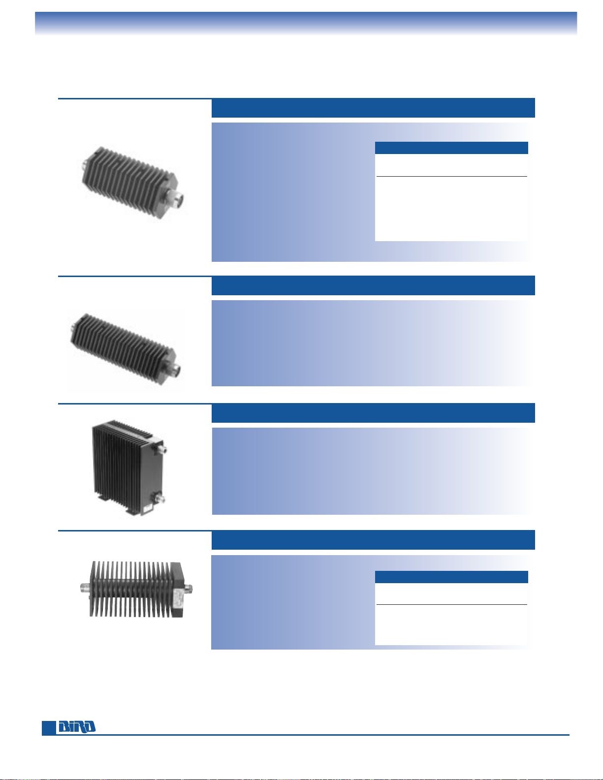
NEW
NEW
56
Phone: 440-248-1200 • Fax: 440-248-5426
TENULINE
®
RF COAXIAL ATTENUATORS
Dry Dielectric
Power Rating: 50 W max. @ 40°C
60 W max. @ 25°C
Connectors: N, BNC, TNC
Frequency Range and VSWR:
DC to 1 GHz at 1.10:1 max.
1 GHz to 2.4 GHz at 1.25:1 max.
Impedance: 50 ohms, nominal
Ambient Temperature Range: –40°C to +40°C
Operating Position: Any
Coolant: Dry (convection cooled)
Finish: Black Anodized.
Silver or Tri-alloy plated connectors
Nominal Size: (with N-type connectors):
5.3" L
× 2.3" Dia.,
(134.7 mm
× 58.5 mm)
50 WATT BI-DIRECTIONAL 50-A SERIES*
Power Rating: 100 W max. @ 40°C
120 W max. @ 25°C
Connectors: N, BNC, TNC, IEC 7/16
Frequency Range and VSWR:
DC to 1 GHz at 1.10:1 max.
1 GHz to 2.4 GHz at 1.25:1 max.
Accuracy: Same as 50-A Series above.
Impedance: 50 ohms, nominal
Ambient Temperature Range: –40°C to +40°C
100 WATT BI-DIRECTIONAL 100-A SERIES*
Weight: 1.25 lbs. (0.57 kg)
Operating Position: Vertical
Coolant: Dry (convection cooled)
Finish: Black semigloss paint per federal
standard 595. Silver or Tri-alloy
plated connectors
Nominal Size: (with N-type connectors):
6.4" H
× 2.6" W × 6.8" D,
(162.6 mm
× 66.1 mm × 172.8 mm)
Weight: 4.3 lbs. (1.95 kg)
Power Range: 100 W continuous
Frequency Range: DC to 1000 MHz
Output: VSWR 1.25
Ambient Temperature Range: –40˚C to +45˚C
Connectors: QC type
(Female N normally supplied)
Coolant: Dry (convection air cooled)
Finish: Black powder coat
Nominal Size: (includes connectors)
7
23
⁄32" × 23⁄4" sq. (196 mm × 70 mm)
100 WATT 8343 SERIES
Weight: 44 oz. (1.25 g)
ACCURACY
dB Accuracy ± dB “XX”
Atten DC–1 GHz 1–2.4 GHz Value
1 0.3 0.5 01
2 0.3 0.5 02
3 0.3 0.5 03
6 0.4 0.6 06
10 0.4 0.8 10
20 0.5 1.0 20
30 0.8 1.3 30
Power Rating: 75 W max. @ 40°C
90 W max. @ 25°C
Connectors: N, BNC, TNC
Frequency Range and VSWR:
DC to 1 GHz at 1.10:1 max.
1 GHz to 2.4 GHz at 1.25:1 max.
Accuracy: Same as 50-A Series above.
Impedance: 50 ohms, nominal
Ambient Temperature Range: –40°C to +40°C
75 WATT BI-DIRECTIONAL 75-A SERIES*
Operating Position: Vertical
Coolant: Dry (convection cooled)
Finish: Black Anodized.
Silver or Tri-alloy plated connectors
Nominal Size: (with N-type connectors):
7.3" H
× 2.3" Dia., (185.5 mm × 58.5 mm)
Weight: 1.6 lbs. (0.73 kg)
ACCURACY
dB Accuracy ± dB and VSWR
Model Atten DC–0.5 GHz 0.5–1 GHz
8343-030 3 0.5 dB, 1.20 0.9 dB, 1.25
8343-060 6 0.5 dB, 1.20 0.9 dB, 1.25
8343-100 10 0.5 dB, 1.15 0.9 dB, 1.20
8343-200 20 0.5 dB, 1.15 0.9 dB, 1.20
*See page 54 for a Model Number Definition that instructs you how to order the correct part.
Page 57
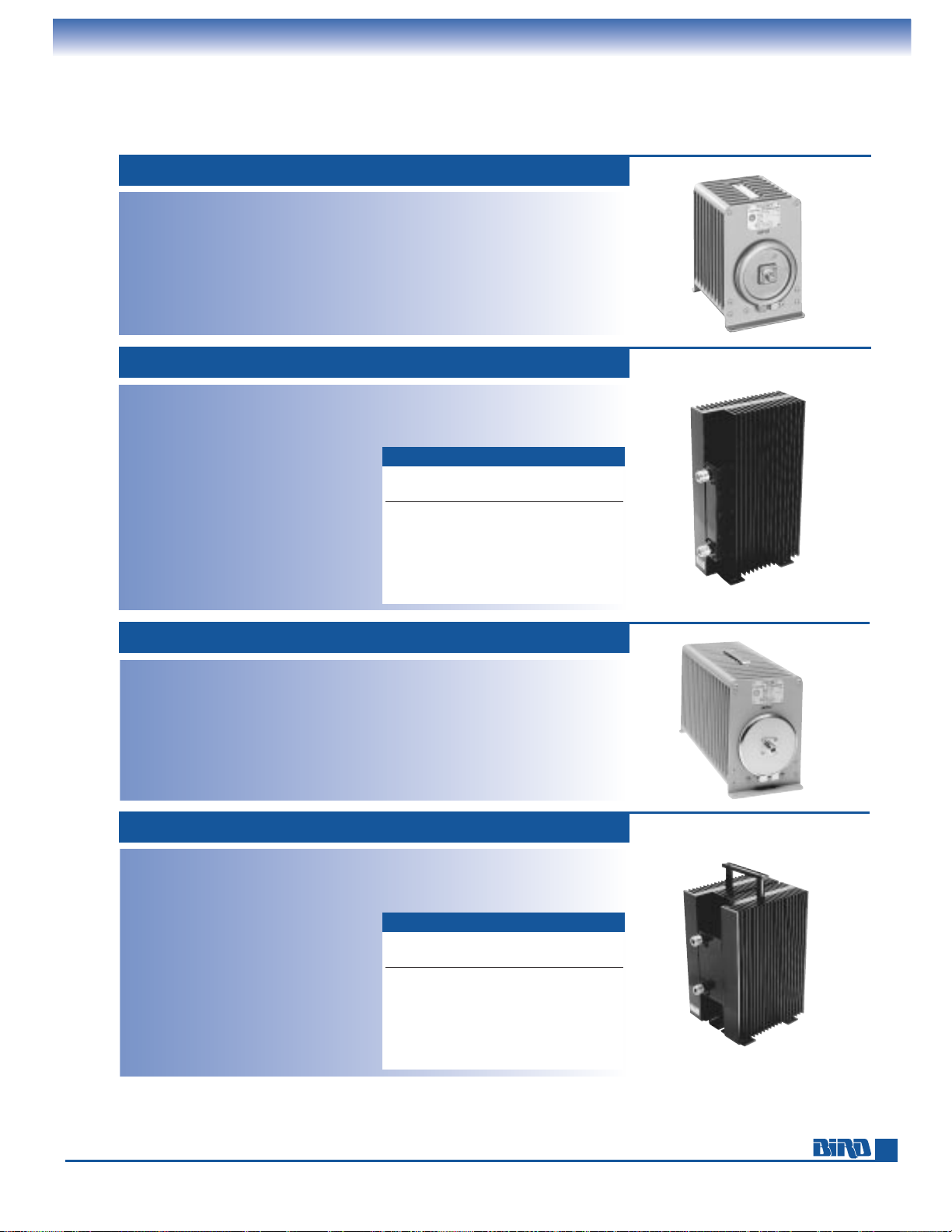
E-mail: [email protected] • Internet: www.bird-electronic.com
100 WATT MODEL 8323
Power Rating: 100 W continuous
Frequency Range and VSWR:
Input 1.1 max. DC to 500 MHz
Attenuation: 30 dB
Accuracy: ±0.5 dB (Calibration data supplied
for 30, 100, 200, 300, 400, and 500 MHz
which is accurate to ±0.2dB)
Ambient Temperature Range: –40˚C to +45˚C
Connectors: QC type
(Female N normally supplied)
Coolant: 0.35 gal. (1.3 liters) refined mineral oil
Operating Position: Horizontal only
Finish: Gray powder coat
Nominal Size: (includes connectors)
1011⁄32" L × 81⁄2" H × 515⁄16" W
(263 mm × 216 mm × 151 mm)
Weight: 11 lbs. (5 kg)
150 WATT BI-DIRECTIONAL 150-A SERIES*
Power Rating: 150 W max. @ 40°C
180 W max. @ 25°C
Connectors: N, TNC, BNC, IEC 7/16
Frequency Range and VSWR:
DC to 1 GHz at 1.10:1 max.
1 GHz to 2.4 GHz at 1.25:1 max.
Impedance: 50 ohms, nominal
Ambient Temperature Range: –40°C to +40°C
Operating Position: Vertical
Cooling: Dry (convection cooled)
Finish: Black semigloss paint per federal
standard 595. Silver or Tri-alloy plated
connectors
Nominal Size: (with N connectors)
1115⁄16" H × 25⁄8" W × 613⁄16" D,
(302 mm × 66 mm × 173 mm)
Weight: 6.5 lb (2.95 kg)
ACCURACY
dB Accuracy ± dB ”XX”
Atten DC–1 GHz 1–2.4 GHz Value
1 0.3 0.5 01
2 0.3 0.5 02
3 0.3 0.5 03
6 0.4 0.6 06
10 0.4 0.8 10
20 0.5 1.0 20
30 0.8 1.3 30
200 WATT MODEL 8322
Power Rating: 200 W continuous
Frequency Range and VSWR:
1.1 max. DC to 500 MHz
Attenuation: 30 dB
Accuracy: ±0.5 dB (Calibration data supplied
for 30, 100, 200, 300, 400, and 500 MHz
which is accurate to ±0.2dB)
Ambient Temperature Range: 40˚C to +45˚C
Connectors: QC type
(Female N normally supplied)
Coolant: 0.7 gal. (2.65 liters) refined mineral oil
Operating Position: Horizontal only
Finish: Gray powder coat
Nominal Size: (includes connectors)
171⁄2" L × 81⁄2" H × 515⁄16" W
(445 mm × 216 mm × 151 mm)
Weight: 19 lbs. (9 kg)
300 WATT BI-DIRECTIONAL 300-A SERIES*
Power Rating: 300 W max. @ 40°C
360 W max. @ 25°C
Connectors: N, TNC, BNC, IEC 7/16
Frequency Range and VSWR:
DC to 1 GHz at 1.10:1 max.
1 GHz to 2.4 GHz at 1.25:1 max.
Impedance: 50 ohms, nominal
Ambient Temperature Range: –40°C to +40°C
Operating Position: Vertical
Cooling: Dry (convection cooled)
Finish: Black semigloss paint per federal
standard 595. Silver or Tri-alloy plated
connectors
Nominal Size: (with N connectors)
1015⁄16" H × 513⁄32" W × 613⁄16" D,
(276.9 mm × 137.2 mm × 172.8 mm)
Weight: 12 lb (5.45 kg)
ACCURACY
dB Accuracy ± dB “XX”
Atten DC–1 GHz 1–2.4 GHz Value
1 0.3 0.5 01
2 0.3 0.5 02
3 0.3 0.5 03
6 0.4 0.6 06
10 0.4 0.8 10
20 0.5 1.0 20
30 0.8 1.3 30
*See page 54 for a Model Number Definition that instructs you how to order the correct part.
Other attenuation values are available on special request.
TENULINE
®
RF COAXIAL ATTENUATORS
Dry and Oil Dielectric
57
Page 58
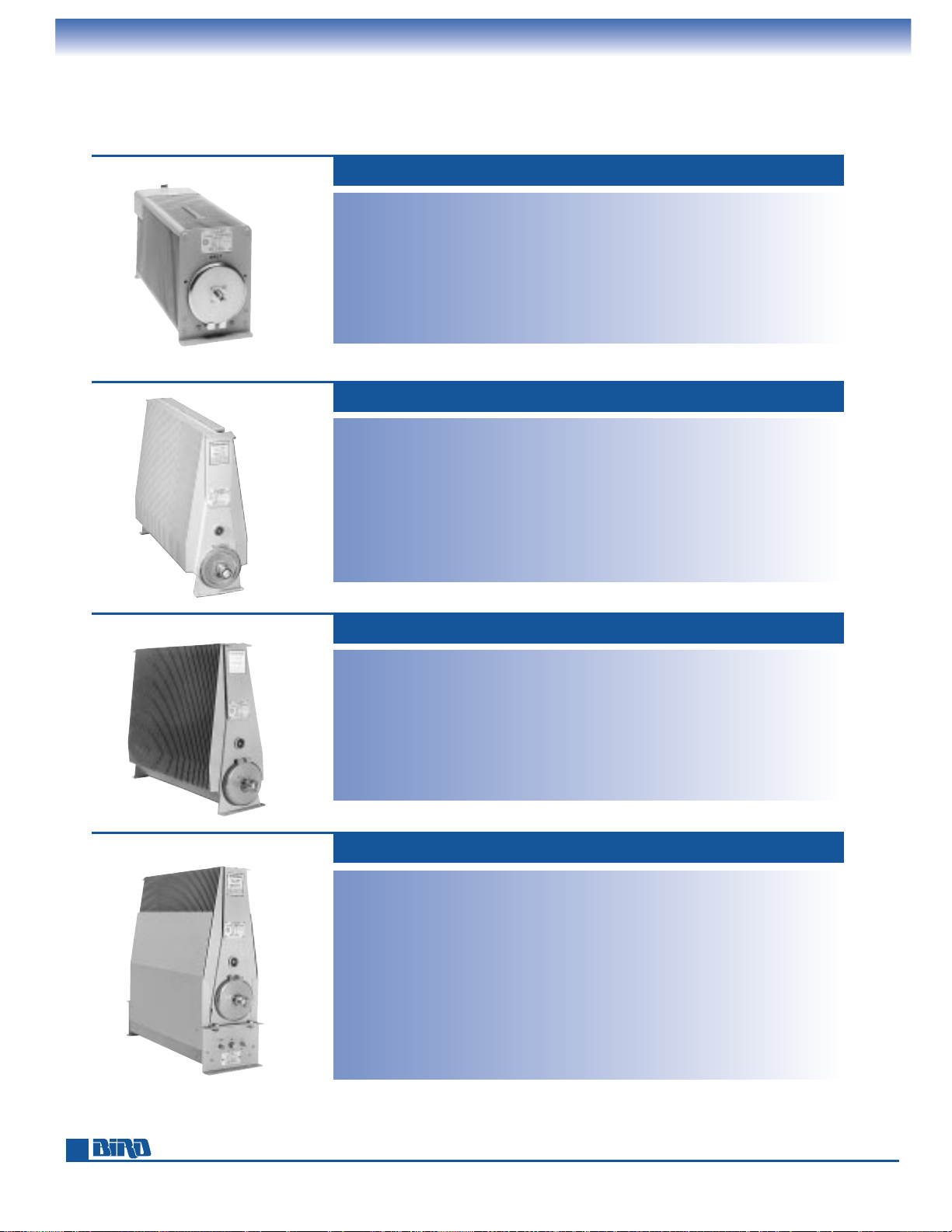
Phone: 440-248-1200 • Fax: 440-248-5426
TENULINE
®
RF COAXIAL ATTENUATORS
Oil-Cooled Dielectric
500 WATT MODEL 8325
Power Rating: 500 W continuous
Frequency Range and VSWR:
Input 1.1 max. DC to 500 MHz
Attenuation: 30 dB
Accuracy: ±0.5 dB (Calibration data supplied
for 30, 100, 200, 300, 400, and 500 MHz
which is accurate to ±0.2dB)
Ambient Temperature Range: –40˚C to +45˚C
Connectors: QC type
(Female N normally supplied)
Coolant: 0.9 gals. (3.4 liters) refined mineral oil
Operating Position: Horizontal only
Finish: Gray powder coat
Nominal Size: (including connectors)
17
1
⁄2" L × 81⁄2" H × 55⁄16" W
(445 mm
× 216 mm × 151 mm)
Weight: 25 lbs. (11 kg)
1 kW MODEL 8327-300
Power Rating: 1000 W continuous
Frequency Range and VSWR:
Input 1.1 max. DC to 500 MHz
Attenuation: 30 dB
Accuracy: ±0.5 dB (Calibration data supplied
for 30, 100, 200, 300, 400, and 500 MHz
which is accurate to ±0.2dB)
Ambient Temperature Range: –40˚C to +45˚C
Connectors: QC type (Female LC input,
Female N output normally supplied,
extra Female N supplied)
Coolant: 2.9 gals. (11 liters) refined mineral oil
Operating Position: Horizontal only
Finish: Gray powder coat
Nominal Size: (including connectors)
23
15
⁄32" L × 173⁄16" H × 71⁄8" W
(596 mm
× 437 mm × 181 mm)
Weight: 57 lbs. (26 kg)
Note: Overload thermoswitch P/N 2450-056
is optional
Bird oil dielectric attenuators have never been and are not now manufactured with Poly Chlorinated
Biphenyls (PCBs).
2 kW MODEL 8329-300
Power Rating: 2000 W continuous
Frequency Range and VSWR:
Input 1.1 max. DC to 500 MHz
Attenuation: 30 dB
Accuracy: ±0.5 dB (Calibration data supplied
for 30, 100, 200, 300, 400, and 500 MHz
which is accurate to ±0.2dB)
Ambient Temperature Range: –40˚C to +45˚C
Connectors: QC type (Female LC input,
Female N output normally supplied)
Coolant: 2.9 gals. (11 liters) silicon oil
Operating Position: Horizontal only
Finish: Gray powder coat
Nominal Size: (including connectors)
23
15
⁄32" L × 173⁄16" H × 71⁄8" W
(596 mm
× 437 mm × 181 mm)
Weight: 57 lbs. (26 kg)
Note: Overload thermoswitch P/N 8329-028
is optional
4 kW MODEL 8329-300 WITH BA-300-115, -230
Power Rating: 4000 W continuous with
blower on, 1000 W with blower off
Frequency Range and VSWR:
Input 1.1 max. DC to 500 MHz
Attenuation: 30 dB
Accuracy: ±0.5 dB (Calibration data supplied
for 30, 100, 200, 300, 400, and 500 MHz
which is accurate to ±0.2dB)
Ambient Temperature Range: –40˚C to +45˚C
Connectors: QC type (Female LC input,
Female N output normally supplied)
Coolant: 2.9 gals. (11 liters) silicone oil
with forced-air cooling
Operating Position: Horizontal only
Finish: Gray powder coat
Nominal Size: (including connectors)
23
15
⁄32" L × 221⁄16" H × 71⁄8" W
(596 mm
× 560 mm × 181 mm)
Weight: 701⁄2lbs. (32 kg)
Blower AC Power:
Model BA-300-115: 115 V, 50/60 Hz, 0.6 A
Model BA-300-230: 230 V, 50/60 Hz, 0.3A
Note: Overload thermoswitch P/N 8329-028
is optional. When ordered as a package,
attenuator and blower are factoryassembled at no additional charge.
58
Page 59
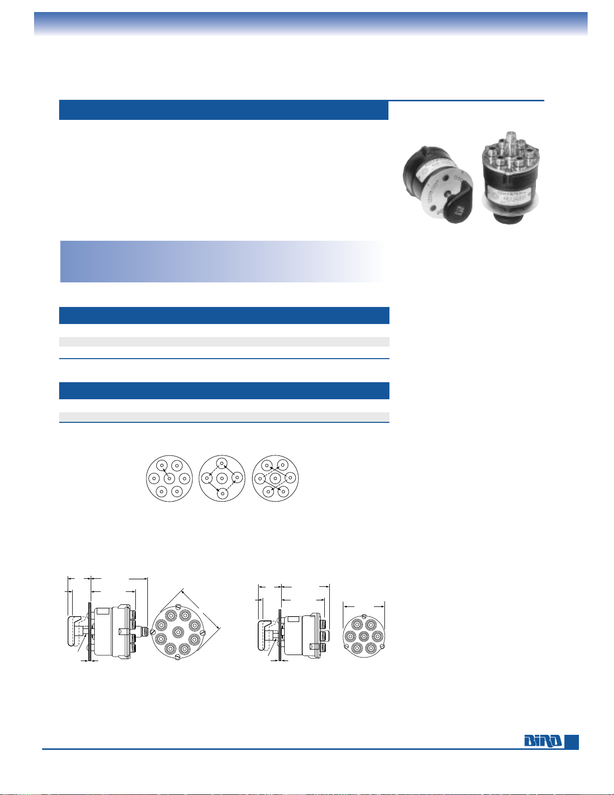
E-mail: [email protected] • Internet: www.bird-electronic.com
3
/8
"
DIA
SHAFT 10
3
/8
"
MAX 10
43/8
"
DIA 108
425/32
"
MAX 121
321/32
"
MAX 93
17/8
"
48 Disengaged
111/32
"
34 Engaged
3
/8
"
DIA
SHAFT 10
3
/8
"
MAX 10
33/8
"
DIA 90
41/16
"
MAX 103
321/32
"
MAX 93
17/8
"
48 Disengaged
111/32
"
34 Engaged
A1
A1
B2
A2 B1
A
B
A2
R1
R2
126
5
43
ACCESSORIES
Selector Switches, Directional Couplers
50-OHM COAXIAL SELECTOR SWITCHES 71, 72, 74 SERIES
Useful Frequency Range: DC to 10 GHz
Maximum RF Voltage: 500 volts rms
Attenuation to Unused Channel:
75 dB (cross talk)
Ambient Temperature Range: –60˚C to +65˚C
(–76˚F to +149˚F)
Weight: Varies by model, approx.
2
1
⁄2lbs. (1.1 kg)
MODEL 74 MODEL 72-R MODEL 72-2
Single-circuit Two-circuit Two-circuit
six position reversing switch two position
Models 74/72-2 mounting dimensions
7
⁄32" (6 mm) mtg holes
for four 10-32 screws spaced at 90˚ on 15⁄16" (33 mm) radius
Models 72-R mounting dimensions
7
⁄32" (6 mm) mtg holes
for three 10-32 screws spaced at 120 ˚ on 11⁄4" (32 mm) radius
The unique, rugged and reliable design of Bird Coaxwitch®Coaxial Selector
Switches permits positive contact, low-insertion VSWR, and negligible cross talk
between channels. The switching mechanism is 4
1
⁄2" of RG-87/U Teflon cable that
pulls away from the mating Male N connectors and rotates to the desired switch
position. These switches cannot be operated accidentally because operation
requires intentionally sequential movement. The knob must be grasped, pulled out,
rotated, and pushed in to make contact.
Installation: Bird switches may be panel mounted. All connectors are located on
the rear of the housing and are parallel to the shaft of the switch. The connecting
cables may be laced together without the use of right-angle adapters.
FREQUENCY VSWR INSERTION LOSS MAX. RF POWER RATING @ 65˚C
100 MHz negligible 0.02 dB 850 W
1000 MHz 1.06 max. 0.09 dB 200 W
4000 MHz 1.30 max. 0.22 dB 75 W
TYPICAL OPERATING VALUES
MODEL 7422 7441 7431 74 718 7181 72-2 72-R
Positions 2 3 4 6 8 10 2 reversing
Coaxial Circuits 1 1 1 1 1 1 2 2
SWITCHING CONFIGURATIONS
59
Page 60
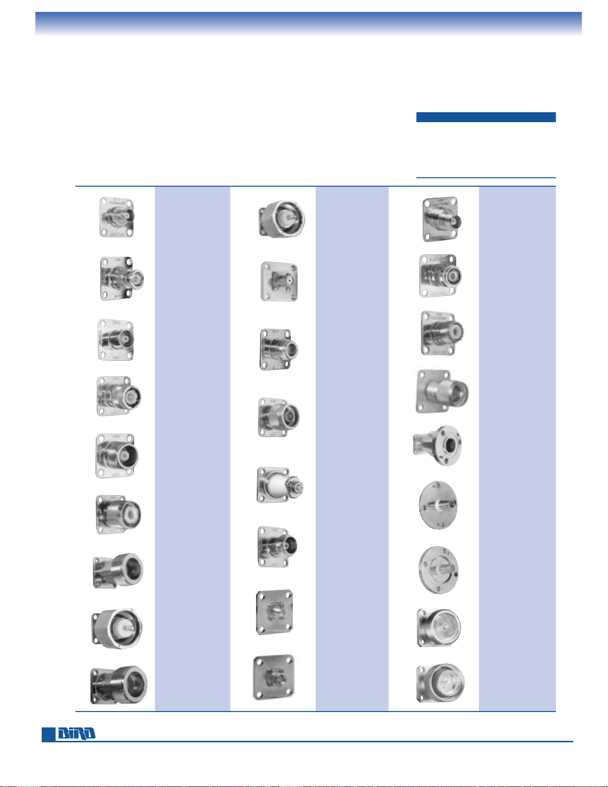
Phone: 440-248-1200 • Fax: 440-248-5426
60
Many TERMALINE®load resistors, attenuators and absorption wattmeters, as well
as THRULINE
®
wattmeters, employ our patented QC-type ”Quick-Change“ RF
Connectors. These products may be ordered with the connector(s) most convenient
for use with your equipment. Many customers order additional connectors to avoid
using performance robbing adapters. QC Connectors are easily changed in the field
by removing and replacing four screws. Because of the wide variety of connectors
and possible applications, electrical specifications for QC-equipped products are
quoted with the standard connectors normally supplied with the equipment.
ACCESSORIES
QC-Type (Quick-Change),
SQC (Small Quick-Change) Connectors
DESCRIPTION PART NUMBER
Female N 4100-014
Male N 4100-015
Female UHF 4100-017
Female TNC 4100-055
Female BNC 4110-014
SQC Connectors, (used with the
4110 Series, 4304 Wattmeter,
8072-1, 8431 Load Resistors, etc.)
are shown below.
TNC (F)
4240-156
TNC (M)
4240-160
UHF (F)
4240-050
UHF (M)
4240-179
7
⁄8" EIA
4240-002
15⁄8" EIA
Fixed
4240-096
15⁄8" EIA
Swivel
4240-208
IEC 7/16 (Jack)
Type 169-4
4240-344
IEC 7/16 (Plug)
Type 169-4
4240-363
BNC (F)
4240-125
BNC (M)
4240-132
C (F)
4240-100
C (M)
4240-110
HN (F)
4240-268
HN (M)
4240-278
LC (F)
4240-031
LC (M)
4240-025
LT (F)
4240-018
LT (M)
4240-012
Mini-UHF (F)
4240-346
N (F)
4240-062
N (M)
4240-063
Open Term.
#10-32 Nut
4240-080
SC (F)
4240-090
SMA (F)
4240-336
SMA (M)
4240-334
Page 61
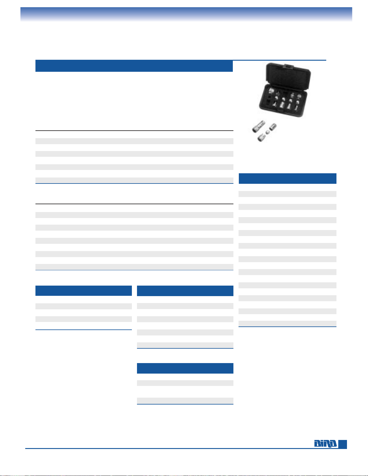
61
N(F) N(M) UHF(F) UHF(M) BNC(F) BNC(M) TNC(F)
N(F) •
N(M) • •
UHF(F) • •
UHF(M) • • •
BNC(F) • • • •
BNC(M) • • • • •
TNC(F) • • • • • •
TNC(M) • • • • • • •
ACCESSORIES
Adapters, Batteries, Cables, Connectors, Coupling Kits
ADAPTER KITS 4240 SERIES
Bird‘s adapter kits let you assemble compact, precision 50-ohm adapters to meet up
to 45 different matching requirements. The adapters offer low VSWR because of
precision machining and tight mating tolerances. The N (F)/N (M) combination, for
example, is below 1.05 to 1 GHz and below 1.1 to 2.5 GHz. The Model 4240-400 lets
you create 30 combinations. The Model 4240-401 can fashion 45 combinations. Both
models include enough couplers to assemble 5 complete adapters at the same time.
MODEL 4240-400
N(F) N(M) BNC(F) BNC(M) TNC(F) TNC(M) SMA(F) SMA(M) UHF(F)
N(F)
N(M)
•
BNC(F) • •
BNC(M) • • •
TNC(F) • • • •
TNC(M) • • • • •
SMA(F) • • • • • •
SMA(M) • • • • • • •
UHF(F) • • • • • • • •
UHF(M) • • • • • • • • •
MODEL 4240-401
* WATTMETER GROUPS
Group I: 3171-020, 3171, 3171A020, 3171A,
3127-055, 3127-080.
Group II: 3127-035, 3127-075, 3127-040, 3127-070.
Group III: 6810-020, 4305A, 6810-030, 4909, 4715,
4610, 4723, 4802.
MODEL USE WITH VOLTS TYPE NOTES
5-1230 4391A 1.25 NiCd 6 Required
5-1587 4412 9 NiCd —
5-1375 4314B, 4410A, 9 Alkaline —
4041, 4410, APM-16
5-1475 4030 3 Li-Mn 3 Required
WATTMETER BATTERIES
MODEL DESCRIPTION
4240-165 QC (F) to QC (F)
4240-180 Copl. (M) to QC (F)
4240-187 3
1
⁄8" Unflg 51.5 ohms to QC (F)
4240-194 3
1
⁄8" Flg. to QC (F)
4240-201
7
⁄8" Flg. to QC (F)
4240-244 Rt. Angle QC
4240-260 1
5
⁄8" Flg. to QC (F)
7500-076 DC conn. plug
QC ADAPTERS, CONNECTORS
MODEL USE WITH DESCRIPTION
3610-031 All Element Sockets Dummy Plug
5-1864 4314B Power Supply 115 V
5-1940 4314B Power Supply 230 V
5A2229 AT Series Power Supply 120 V
5A2226 AT Series Power Supply 230 V
MISCELLANEOUS
USE WITH
MODEL CONNECTOR LENGTH
GROUP
3170-058-1 BNC (M) 14" 1
3170-058-6 BNC (M) 6’ 1
3170-058-2 BNC (M) 15’ 1
3170-058-3 BNC (M) 25’ 1
3170-058-4 BNC (M) 40’ 1
3170-058-5 BNC (M) 50’ 1
3170-058-7 BNC (M) 80’ 1
3170-058-8 BNC (M) 90’ 1
3170-058-9 BNC (M) 100’ 1
4220-097-5 Spade Lug 16" II
4220-097-1 Spade Lug 33" II
4220-097-22 Spade Lug 48" II
4220-097-7 Spade Lug 10’ II
4220-097-9 Spade Lug 15’ II
4220-097-10 Spade Lug 25’ II
4220-097-17 Spade Lug 50’ II
4220-097-13 Spade Lug 75’ II
4220-097-16 Spade Lug 100’ II
7500-072-1 DC Plug 39
1
⁄2’ III
7500-072-3 DC Plug 5’ III
7500-072-4 DC Plug 10’ III
7500-072-2 DC Plug 25’ III
DC CABLE ASSEMBLIES*
RG-58/U cables with a Model 7500-076
DC plug on one end and the connector
in the table below on the other end.
Page 62
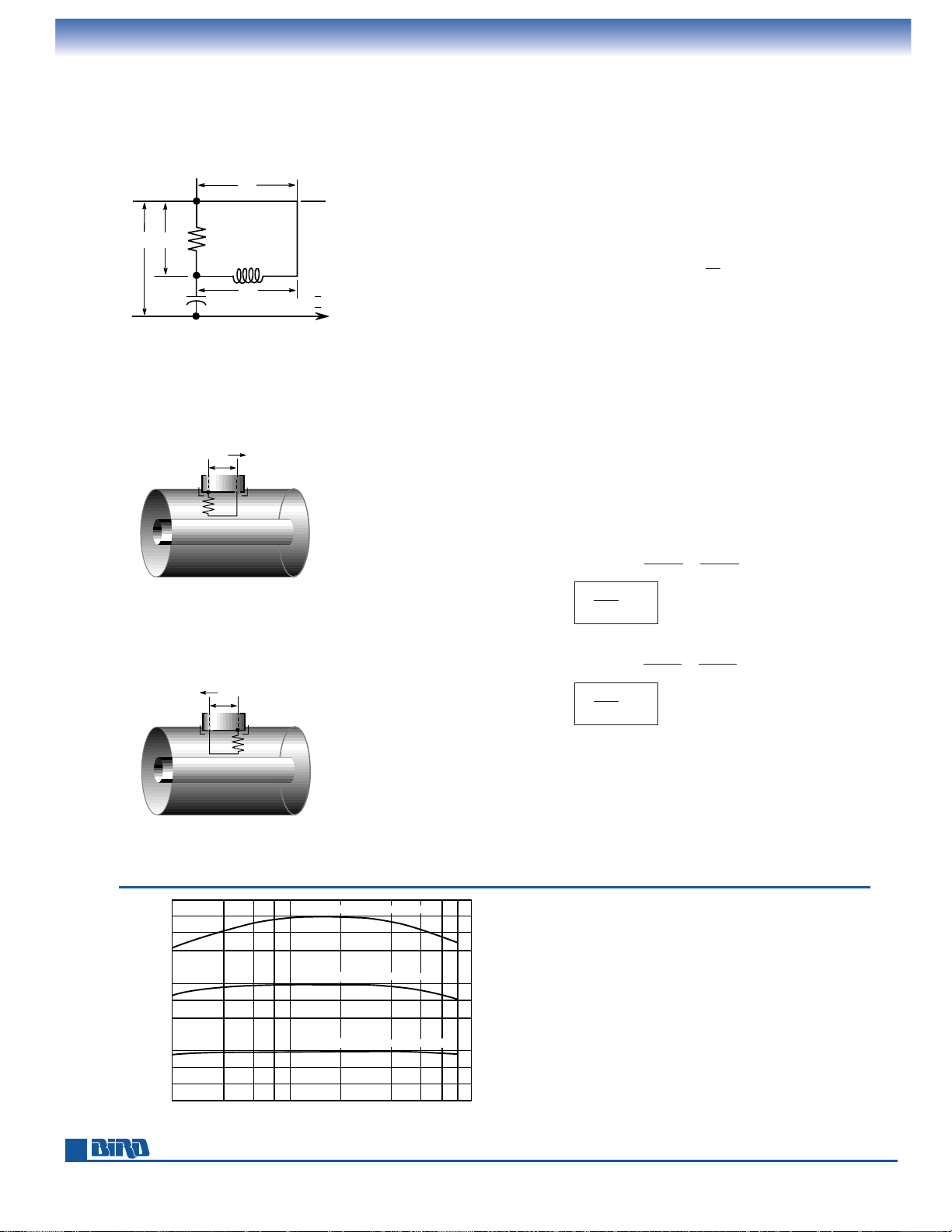
Phone: 440-248-1200 • Fax: 440-248-5426
M
e
M
C
R
e
R
E
e
e
I
+
M
e
Figure 2
–
M
e
Figure 3
RELATIVE RESPONSE
10C ELEMENT: 10 W, 100 – 250 MHZ
20 40 60 80 100 200 400 600 800 1000
0 dB
– 5 dB
– 10 dB
0 dB
– 5 dB
– 10 dB
0 dB
– 5 dB
– 10 dB
100C ELEMENT: 10 W, 100 – 250 MHZ
5000 ELEMENT: 500 W, 100 – 250 MHZ
Figure 4
62
TECHNICAL DATA
THRULINE®principle
eRfrom the division of E by R and C, eR= RE= RE jvC
X
C
(if R << XC), and eMby induction eM= Ijv (±M).
The sum e
R
+ eM= jv(CRE ±MI) = e
Besides selecting R very much smaller that x
C
, the components of the circuit are
chosen so that
CR = M/Z°.
The output voltage is now
e =
jv(EM/Z
°
±
MI) = jvM(E/Z
°
±
I)
At any one point on a transmission line, the voltage E is the sum of the forward
and reflected voltages E
f
+ Er, and the current I is Ef/Z°– Er/Z°(Since the reflected
wave travels in the opposite direction,
Ir= – Er/Z°).
When the element is pointing toward the load, the output voltage is
e
➝ = jvM(E/ Z
°
+
I) = jvM
{
Ef+ E
r
+
E
f
– E
r
}
=
=
j
vM
(2Ef)
Z
°
and turning the element toward the source, it becomes ...
e =
jvM(E/Z°– I) = jvM
{
Ef+ E
r
+
E
f
– E
r
}
=
=
j
vM
(2Er)
Z
°
We have now proved what we set out to show, namely that the RF output voltage
from the sensing element is directional and proportional to the voltage in the line due
to either the forward or the reflected wave. It is also directly proportional to
v, that
is to frequency (
v = 2πf). In order to make it frequency independent, we terminate
e in a capacitive reactance which is inversely proportional to
v. The voltage across
this capacitor is rectified, filtered and displayed on a meter calibrated in RF watts.
For additional details on THRULINE
®
principles, write for “WATT’S NEW FROM
BIRD” vol. 2 no. 2.
The basic sensing circuit of a THRULINE
®
plug-in element consists of the mutual
inductance M between the loop and the center conductor and the voltage divider
C and R. In Fig. 1, E is the voltage between outer and center conductor and
I is the
current. Elements can be rotated 180˚, resulting in either a positive or a negative
M (Fig. 2 and 3). The output voltage in this lumped-constant directional coupler is
the sum of two samples:
Z
°
Z
°
➝
Z
°
Z
°
Frequency Response THRULINE®Elements,
100–250 MHz (C-Series)
Higher power elements have flatter frequency characteristics
than tighter coupled lower-power units. Beyond the stated
frequency range, measurement results cannot be predicted.
Figure 1
Page 63
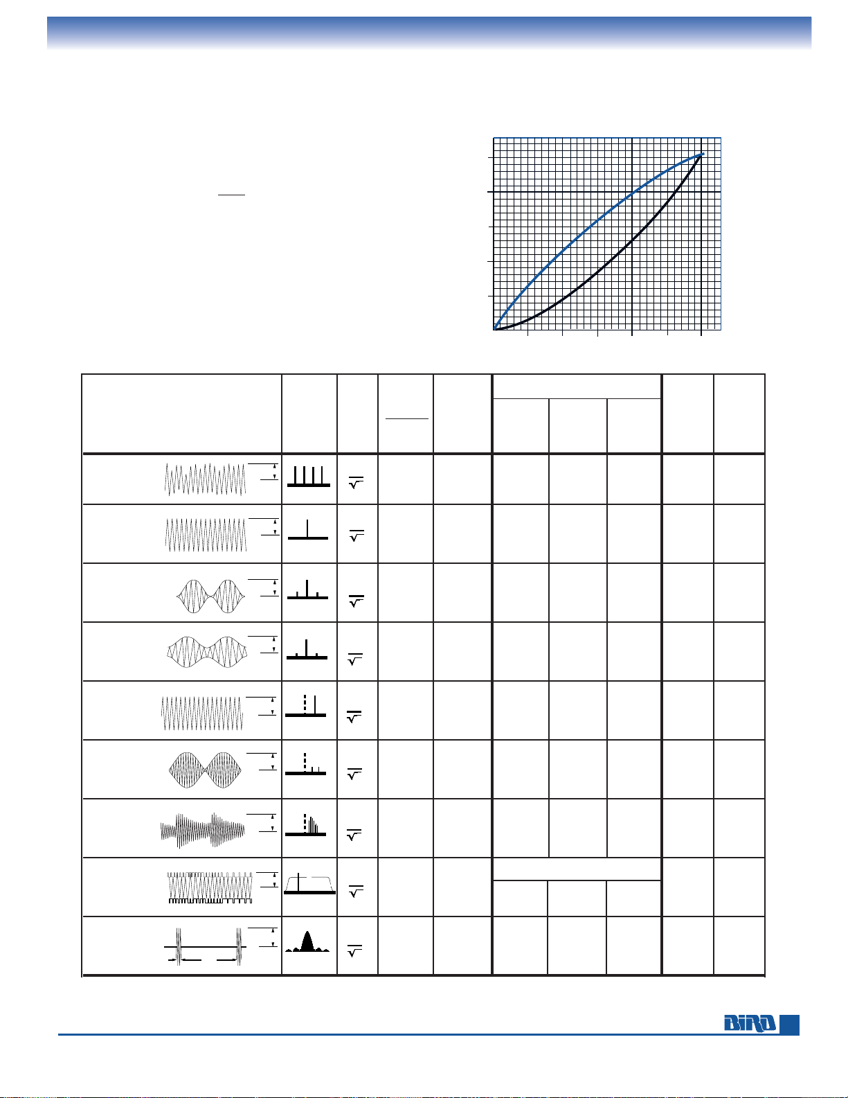
Transmission Type Frequency PEV
RMS
PEP = P
AVE
Models 4314B, 4391A
Model 43 Model
and Scope Pattern Spectrum
(arbitrary)
PEV
2
RMS
(Average
CW PEP% MOD 4304A, APM-16
(C = Carrier)
Z
0
Heating Mode Mode Mode 4308
Power)
Table A
Multiple 1600W 400W — 1600W — — 400W
Carriers
Table B
CW 100W 100W 100W 100W 0% 100W 100W
Table C
AM 400W 150W 100W 400W 100% 100W 150W
100% Mod.
Table D
AM 300W 127W 100W 300W 73% 100W 127W
75% Mod.
Table E
SSB 100W 100W 100W 100W 0% 100W 100W
1 Tone
Table F
SSB 100W 50W 25W 100W 100% 40.5W 50W
2 Tones
Table G
SSB 100W — — 100W — — —
Voice
Table H
Models 4314B, 4391A only
TV Black 100W 60.1W
— 100W —
59.6W 60.1W
Level
Table 1
Pulse 100W 10W — 100W 100% — 10W
63
TECHNICAL DATA
Interpreting readings on peak
Wattmeters with Multicarrier, CW, AM, SSB, and pulsed signals
1 2 3 4
1.5
1.4
1.3
1.2
1.1
1.0
P /PC
PEP/PC
100
80
60
40
20
0
% MODULATION (AM)
AVE
In the table below, Z°= 50 ohms, PEP is peak envelope power,
and PEV is peak envelope voltage. The PEV of the carrier
(or suppressed carrier) C was arbitrarily chosen at 100 volts
in all examples, PEV
RMS
= . To obtain a detailed essay on
this subject, write for ”WATT’S NEW FROM BIRD” vol. 4, no. 2.
For TV black level measurement (table H), refer to vol. 5, no. 3.
The graph at right shows correlation of peak-envelope-power
(PEP), average heating power (P
AVE
) and % modulation of
AM signals for Tables B, C, and D below.
PEV
1.414
Figure 1
CC CCCC CC
400400
VV
400V400V
22
100100
VV
CC
100V100V
22
200200
VV
CC
200V200V
22
173173
VV
CC
173V173V
22
100100
VV
(C)(C)
100V100V
22
(C)(C)
100100
VV
100V100V
22
100V100V
CC
100100
VV
22
CC
100100
VV
100V100V
10%10% 90%90%
22
(C)(C)
100100
VV
100V100V
22
Page 64
Phone: 440-248-1200 • Fax: 440-248-5426
64
TECHNICAL DATA
Required length of cable to equal 1⁄2 or 1 wavelength
when added to a THRULINE®wattmeter
FREQUENCY MHz
0 100 200 300 400 500 600
36
32
28
24
20
16
12
8
4
CABLE LENGTH (inches)
10
9
8
7
6
5
4
600 700 800 900 1000
1) Physical cable length shown in inches is measured from
end to end of outer conductor of connectors (TNC and
N Male connectors), except for cables with UHF or MiniUHF plugs where the cable length is measured from tip
to tip of the center pins.
2) Dimensions shown are for solid polyethylene cable (e.g.
RG-58C/U, RG-8/U) which has 66% the velocity of propagation relative to air. If so-called ”RG-58 type“ or ”RG-8
type“ cables (which often contain foam polyethylene)
are used, the dimensions in the graph must be multiplied
by that cable’s relative velocity (say 79%) divided by 66%
(i.e. by a factor of 79% ÷ 66% = 1.2).
TYPICAL PEAK POWER RATINGS
When a Model APM-16, 43, 4431, 4314B or 4391A is used to match
a load to a transmitter and a good match is obtained, removing
the instrument will not cause any change in the conditions,
since a good 50 ohm load can be placed at the end of a 50 ohm
transmission line of any length without altering conditions at
the transmitter.
What happens when the load is not well matched, like an antenna
with a VSWR of 1.5 or 2.0? Since the length of line between a
mismatched load and the source transforms the impedance of the
load as seen at the source, line length now becomes critical. If the
adjustments for maximum power transfer were made with the
Model 43 in place, removing it shortens the line by four inches, plus
two connectors. This still is no cause for concern at low frequencies
where four to five inches is a small fraction of a wavelength.
At higher frequencies; e.g., above 100 MHz, power output and
frequency of the source may be affected.
It is a principle of transmission line theory that the impedance is
identical on either side of
1
⁄2wavelengths. In order to duplicate
the conditions in your transmission line with the above Model
wattmeters either in or out of the line, it is only necessary to insert
or remove one or more
1
⁄2wavelengths. This is easily done by
making up a length of cable which, when added to the THRULINE
®
,
equals one or more
1
⁄2wavelengths at the frequency of measurement. If more than one frequency is involved, one cable is needed
for each frequency.
AVG. PULSE WIDTH (µs)
MODELS
POWER 1 10 100 1000 5000
Oil Dielectric Loads
8135 150 W 10 kW 8.0 kW 5.75 kW 3.5 kW 2.0 kW
8201 500 W 200 kW 150 kW 105 kW 57 kW 25 kW
8251 1000 W 200 kW 150 kW 105 kW 57 kW 25 kW
8890 Series 2.5 kW 150 kW 115 kW 80 kW 54 kW 22 kW
8920 Series 5 kW 150 kW 115 kW 80 kW 54 kW 22 kW
8930 Series 10 kW 150 kW 120 kW 85 kW 55 kW 30 kW
Direct Water-Cooled Loads
8730 Series 10 kW 100 kW 77 kW 56 kW 32 kW 16 kW
8740 Series 20 kW 250 kW 190 kW 135 kW 75 kW 35 kW
8750 Series 30 kW 250 kW 190 kW 135 kW 75 kW 40 kW
8760 Series 40 kW 250 kW 197 kW 145 kW 90 kW 55 kW
8770 Series 50 kW 250 kW 197 kW 145 kW 97 kW 65 kW
8790 Series 80 kW 250 kW 210 kW 170 kW 130 kW 100 kW
Note: The duty factor should be such that
the average power rating of the load is
never exceeded.
Page 65
65
INDEX
By Product and Model Number
****–677-1 . . . . . . . . . . . . . . . . . 53
****–677-2 . . . . . . . . . . . . . . . . . 53
10-A . . . . . . . . . . . . . . . . . . . . . . 55
10-T. . . . . . . . . . . . . . . . . . . . . . . 43
100-A . . . . . . . . . . . . . . . . . . . . . 56
100-T. . . . . . . . . . . . . . . . . . . . . . 44
100-CT. . . . . . . . . . . . . . . . . . . . . 44
150-A . . . . . . . . . . . . . . . . . . . . . 57
150-T. . . . . . . . . . . . . . . . . . . . . . 45
150-CT. . . . . . . . . . . . . . . . . . . . . 45
2-A . . . . . . . . . . . . . . . . . . . . . . . 55
2-A-MFA-XX . . . . . . . . . . . . . . . . 54
2-T. . . . . . . . . . . . . . . . . . . . . . . . 43
25-A . . . . . . . . . . . . . . . . . . . . . . 55
25-T. . . . . . . . . . . . . . . . . . . . . . . 43
25-CT. . . . . . . . . . . . . . . . . . . . . . 43
250-CT. . . . . . . . . . . . . . . . . . . . . 45
300-A . . . . . . . . . . . . . . . . . . . . . 57
300-T. . . . . . . . . . . . . . . . . . . . . . 46
3126A . . . . . . . . . . . . . . . . . . . . . 33
3127-035 . . . . . . . . . . . . . . . . . . . 35
3127-040 . . . . . . . . . . . . . . . . . . . 35
3127-055 . . . . . . . . . . . . . . . . . . . 35
3127-070 . . . . . . . . . . . . . . . . . . . 35
3127-075 . . . . . . . . . . . . . . . . . . . 35
3127-080 . . . . . . . . . . . . . . . . . . . 35
3127A . . . . . . . . . . . . . . . . . . . . . 33
3128A . . . . . . . . . . . . . . . . . . . . . 19
3170-058-1 . . . . . . . . . . . . . . . . . 61
3170-058-2 . . . . . . . . . . . . . . . . . 61
3170-058-3 . . . . . . . . . . . . . . . . . 61
3170-058-4 . . . . . . . . . . . . . . . . . 61
3170-058-5 . . . . . . . . . . . . . . . . . 61
3170-058-6 . . . . . . . . . . . . . . . . . 61
3170-058-7 . . . . . . . . . . . . . . . . . 61
3170-058-8 . . . . . . . . . . . . . . . . . 61
3170-058-9 . . . . . . . . . . . . . . . . . 61
3170A . . . . . . . . . . . . . . . . . . . . . 20
3171A . . . . . . . . . . . . . . . . . . . . . 32
3171A020 . . . . . . . . . . . . . . . . . . 32
3610-031 . . . . . . . . . . . . . . . . . . . 61
4022 . . . . . . . . . . . . . . . . . . . . . . . 6
4023 . . . . . . . . . . . . . . . . . . . . . . . 6
4024 . . . . . . . . . . . . . . . . . . . . . . . 6
4025 . . . . . . . . . . . . . . . . . . . . . . . 6
4030 . . . . . . . . . . . . . . . . . . . . . . 22
4041 . . . . . . . . . . . . . . . . . . . . . . 22
4100-014 . . . . . . . . . . . . . . . . . . . 60
4100-015 . . . . . . . . . . . . . . . . . . . 60
4100-017 . . . . . . . . . . . . . . . . . . . 60
4100-055 . . . . . . . . . . . . . . . . . . . 60
4110-014 . . . . . . . . . . . . . . . . . . . 60
4152-220 . . . . . . . . . . . . . . . . . . . 18
4163-240 . . . . . . . . . . . . . . . . . . . 18
4164-240 . . . . . . . . . . . . . . . . . . . 18
4169-300 . . . . . . . . . . . . . . . . . . . 18
4201 . . . . . . . . . . . . . . . . . . . . . . 18
4201A501 . . . . . . . . . . . . . . . . . . 18
4201A502 . . . . . . . . . . . . . . . . . . 18
4201A503 . . . . . . . . . . . . . . . . . . 18
4201A504 . . . . . . . . . . . . . . . . . . 18
4210A100 . . . . . . . . . . . . . . . . . . 23
4220-097-1 . . . . . . . . . . . . . . . . . 61
4220-097-10 . . . . . . . . . . . . . . . . 61
4220-097-13 . . . . . . . . . . . . . . . . 61
4220-097-16 . . . . . . . . . . . . . . . . 61
4220-097-17 . . . . . . . . . . . . . . . . 61
4220-097-22 . . . . . . . . . . . . . . . . 61
4220-097-5 . . . . . . . . . . . . . . . . . 61
4220-097-7 . . . . . . . . . . . . . . . . . 61
4220-097-9 . . . . . . . . . . . . . . . . . 61
4230-006-1 . . . . . . . . . . . . . . . . . 23
4230-018 . . . . . . . . . . . . . . . . . . . 23
4230-053 . . . . . . . . . . . . . . . . . . . 23
4230-059 . . . . . . . . . . . . . . . . . . . 23
4240-002 . . . . . . . . . . . . . . . . . . . 60
4240-012 . . . . . . . . . . . . . . . . . . . 60
Absorption Wattmeters . . . . . . . . . . . . . . . . . . . . . 39–41
Antenna Testers . . . . . . . . . . . . . . . . . . . . . . . . . . . . . 4–5
Attenuators . . . . . . . . . . . . . . . . . . . . . . . . . . . . . . 54–58
Bi-directional . . . . . . . . . . . . . . . . . . . . . . . . . . . 54–57
Dry, 2 – 40 W . . . . . . . . . . . . . . . . . . . . . . . . . . . 54–55
Dry, 50 – 100 W . . . . . . . . . . . . . . . . . . . . . . . . . 56–57
Dry, 150 – 300 W . . . . . . . . . . . . . . . . . . . . . . . . . . . 57
Oil, 100 – 200 W. . . . . . . . . . . . . . . . . . . . . . . . . 56–57
Oil, 0.5 – 4 kW. . . . . . . . . . . . . . . . . . . . . . . . . . . . . 58
Selection Guide . . . . . . . . . . . . . . . . . . . . . . . . . . . . 54
Batteries. . . . . . . . . . . . . . . . . . . . . . . . . . . . . . . . . . . . 61
Bus Interfaces. . . . . . . . . . . . . . . . . . . . . . . . . . . . . . . . 21
Blower Assemblies . . . . . . . . . . . . . . . . . . . . . . . . . 48, 58
Cable Assemblies, DC. . . . . . . . . . . . . . . . . . . . . . . . . . 61
Calibration Kits . . . . . . . . . . . . . . . . . . . . . . . . . . . . . . . 7
Calorimeters. . . . . . . . . . . . . . . . . . . . . . . . . . . . . . . . . . 8
Cases . . . . . . . . . . . . . . . . . . . . . . . . . . . . . . . . . . . . 7, 24
CE Mark . . . . . . . . . . . . . . . . . . . . . . . . . . . . . . . . . . . . . 3
Cigarette Lighter Adapter . . . . . . . . . . . . . . . . . . . . . . . 5
Coaxial Selector Switches. . . . . . . . . . . . . . . . . . . . . . . 59
Connectors . . . . . . . . . . . . . . . . . . . . . . . . . . . . 53, 60–61
Adapter Kits . . . . . . . . . . . . . . . . . . . . . . . . . . . . . . 61
Flange to Flange Adapters . . . . . . . . . . . . . . . . . . . 53
Flange to QC Adapters . . . . . . . . . . . . . . . . . . . . . . 61
SQC . . . . . . . . . . . . . . . . . . . . . . . . . . . . . . . . . . . . . 60
QC . . . . . . . . . . . . . . . . . . . . . . . . . . . . . . . . . . . . . . 60
QC Adapters . . . . . . . . . . . . . . . . . . . . . . . . . . . . . . 61
Coolants. . . . . . . . . . . . . . . . . . . . . . . . . . . . . . . . . . . . 53
Coupling Kits . . . . . . . . . . . . . . . . . . . . . . . . . . . . . . . . 53
Directional Couplers. . . . . . . . . . . . . . . . . . . . . . . . 28, 59
Dollies . . . . . . . . . . . . . . . . . . . . . . . . . . . . . . . . . . . . . 53
Duct, Hot Air . . . . . . . . . . . . . . . . . . . . . . . . . . . . . . . . 53
Dummy Loads (See Terminations)
ECONOLOADS
®
. . . . . . . . . . . . . . . . . . . . . . . . . . . 50–51
Elements (See Plug-in Elements)
Field Strength Meters . . . . . . . . . . . . . . . . . . . . . . . . . 22
Flange Adapters. . . . . . . . . . . . . . . . . . . . . . . . . . . . . . 53
Interfaces . . . . . . . . . . . . . . . . . . . . . . . . . . . . . . . . . . . 21
Line Sections . . . . . . . . . . . . . . . . . . . . . . . . . . . . . 23, 34
7
⁄8" . . . . . . . . . . . . . . . . . . . . . . . . . . . . . . . . . . . . . . 23
1
5
⁄8" to 61⁄8" . . . . . . . . . . . . . . . . . . . . . . . . . . . . . . 34
Loads (See Terminations)
Meter Movements . . . . . . . . . . . . . . . . . . . . . . . . . 23, 35
Housed. . . . . . . . . . . . . . . . . . . . . . . . . . . . . . . . 23, 35
Panel Mount . . . . . . . . . . . . . . . . . . . . . . . . . . . . . . 35
Round . . . . . . . . . . . . . . . . . . . . . . . . . . . . . . . . . . . 23
MODULOADS
®
. . . . . . . . . . . . . . . . . . . . . . . . . . . . 51–52
Mounting Brackets . . . . . . . . . . . . . . . . . . . . . . . . . . . 53
Oil Dielectric Coolant. . . . . . . . . . . . . . . . . . . . . . . . . . 53
Parts . . . . . . . . . . . . . . . . . . . . . . . . . . . . . . . . . 23, 53, 61
Peak Power Kit, Model 43 . . . . . . . . . . . . . . . . . . . . . . 13
Plug-in Elements . . . . . . . . . . . . . . . 11, 22, 25–28, 36–38
APM. . . . . . . . . . . . . . . . . . . . . . . . . . . . . . . . . . 11, 28
Directional Coupler . . . . . . . . . . . . . . . . . . . . . . 28, 36
Dummy Plug . . . . . . . . . . . . . . . . . . . . . . . . . . . . . . 61
Field Strength . . . . . . . . . . . . . . . . . . . . . . . . . . . . . 22
For 1
5
⁄8" Lines . . . . . . . . . . . . . . . . . . . . . . . . . . . . . 37
For 3
1
⁄8" Lines . . . . . . . . . . . . . . . . . . . . . . . . . . . . . 37
For 4
1
⁄16" Lines . . . . . . . . . . . . . . . . . . . . . . . . . . . . 38
For 6
1
⁄8" Lines . . . . . . . . . . . . . . . . . . . . . . . . . . . . . 38
For Model 4410A. . . . . . . . . . . . . . . . . . . . . . . . . . . 27
For Model 4305A. . . . . . . . . . . . . . . . . . . . . . . . 27, 37
High Frequency . . . . . . . . . . . . . . . . . . . . . . . . . . . . 26
High Power . . . . . . . . . . . . . . . . . . . . . . . . . 27, 37–38
Low Power. . . . . . . . . . . . . . . . . . . . . . . . . . . . . 25, 26
Low Frequency . . . . . . . . . . . . . . . . . . . . . . . . . . . . 26
Milliwatt . . . . . . . . . . . . . . . . . . . . . . . . . . . . . . . . . 26
Sampler . . . . . . . . . . . . . . . . . . . . . . . . . . . . . . . . . . 28
Selection Guides . . . . . . . . . . . . . . . . . . . . . . . . . 25,36
Standard . . . . . . . . . . . . . . . . . . . . . . . . . . . . . . . . . 25
Power Alarm Systems . . . . . . . . . . . . . . . . . 19–20, 32–33
POWER ANALYST
®
Wattmeter . . . . . . . . . . . . . . . . . . 21
Power Supplies. . . . . . . . . . . . . . . . . . . . . . . . . . . . . . . 61
Power Sensors . . . . . . . . . . . . . . . . . . . . . . . . . . . . . 6, 18
Power Meters (See Wattmeters)
QC-Connectors. . . . . . . . . . . . . . . . . . . . . . . . . . . . . . . 60
Resistors, Replacement . . . . . . . . . . . . . . . . . . . . . . . . 53
Rigid Line Sections . . . . . . . . . . . . . . . . . . . . . . . . . 23, 34
Selection Guides . . . . . . . . . . . . . 9, 25, 29, 36, 39, 42, 54
Attenuator . . . . . . . . . . . . . . . . . . . . . . . . . . . . . . . 54
Plug-in Element . . . . . . . . . . . . . . . . . . . . . . . . . 25, 36
Termination. . . . . . . . . . . . . . . . . . . . . . . . . . . . . . . 42
Wattmeter . . . . . . . . . . . . . . . . . . . . . . . . . . . 9, 29, 39
Sensors, Power. . . . . . . . . . . . . . . . . . . . . . . . . . . . . 6, 18
Signal Sampler . . . . . . . . . . . . . . . . . . . . . . . . . . . . . . . 22
Signal Sampler Elements . . . . . . . . . . . . . . . . . . . . . . . 28
Software . . . . . . . . . . . . . . . . . . . . . . . . . . . . . . . . . . . 5,7
SQC Connectors . . . . . . . . . . . . . . . . . . . . . . . . . . . . . . 60
Switches . . . . . . . . . . . . . . . . . . . . . . . . . . . . . . . . . 53, 59
Technical Data . . . . . . . . . . . . . . . . . . . . . . . . . . . . 62–64
Terminations. . . . . . . . . . . . . . . . . . . . . . . . . . . . . . 42–53
Accessories. . . . . . . . . . . . . . . . . . . . . . . . . . . . . . . . 53
Dry, 2 – 75 W . . . . . . . . . . . . . . . . . . . . . . . . . . . 43–44
Dry and Oil, 100 – 250 W. . . . . . . . . . . . . . . . . . 44–45
Dry and Oil, 300 – 600 W. . . . . . . . . . . . . . . . . . 46–47
Dry Forced-Air, 10 – 15 kW . . . . . . . . . . . . . . . . . . . 52
Dry Forced-Air, 25 kW . . . . . . . . . . . . . . . . . . . . . . . 53
ECONOLOADS
®
, 10 – 80 kW. . . . . . . . . . . . . . . . 50–51
MODULOADS
®
, 10 – 50 kW . . . . . . . . . . . . . . . . 51, 52
Oil, 1 – 2.5 kW . . . . . . . . . . . . . . . . . . . . . . . . . . 47–48
Oil, 5 – 10 kW . . . . . . . . . . . . . . . . . . . . . . . . . . 48–49
Selection Guide . . . . . . . . . . . . . . . . . . . . . . . . . . . . 42
Water, 1 kW. . . . . . . . . . . . . . . . . . . . . . . . . . . . . . . 48
Water, 5 – 30 kW . . . . . . . . . . . . . . . . . . . . . . . . . . . 50
Water, 40 – 80 kW . . . . . . . . . . . . . . . . . . . . . . . . . . 51
Terms and Conditions (See separate price list)
Test Sets. . . . . . . . . . . . . . . . . . . . . . . . . . . . . . . . . . . . 14
Thermoswitches . . . . . . . . . . . . . . . . . . . . . . . . . . . 48, 53
Water Flow Switches . . . . . . . . . . . . . . . . . . . . . . . . . . 53
WATTCHER
®
Systems . . . . . . . . . . . . . . . . . 19–20, 32–33
Wattmeters . . . . . . . . . . . . . . . . . 6–21, 29–33, 35, 39–41
Absorption. . . . . . . . . . . . . . . . . . . . . . . . . . . . . 39–41
Accessories (See specific item)
Advanced Power Measurement . . . . . . . . . . . . . . . 11
Alarm Systems . . . . . . . . . . . . . . . . . . . . 19–20, 32–33
Average Reading. . . . . . . . . . . . . . . . . . . . . . . . . . . 11
Calorimeters . . . . . . . . . . . . . . . . . . . . . . . . . . . . . . . 8
Cellular. . . . . . . . . . . . . . . . . . . . . . . . . . . . . 11, 15, 18
Digital Display . . . . . . . . . . . . . . . . . . . . . . . . . 6, 8, 21
Elements (See Plug-in Elements)
High Power . . . . . . . . . . . . . . . . . . . . . . 14, 30–33, 35
Laboratory Grade . . . . . . . . . . . . . . . . . . . . . . . . . 6–8
Model 43 . . . . . . . . . . . . . . . . . . . . . . . . . . . . . . . . . 12
Multichannel . . . . . . . . . . . . . . . . . . . . . . . . . . . . . . 18
Multifunction. . . . . . . . . . . . . . . . . . . . . . . . . . 6–7, 21
Multirange . . . . . . . . . . . . . . . . . . . . . . . . . 6–7, 15, 16
Panel/Rack Mount. . . . . . . . . . . . . . . 17–20, 32–33, 35
Parts (See specific item)
PEP. . . . . . . . . . . . . . . . . . . . . . . . . . . . . . . . . . . . . . 13
RF Tap . . . . . . . . . . . . . . . . . . . . . . . . . . . . . . . . 14, 17
Selection Guides . . . . . . . . . . . . . . . . . . . . . . 9, 29, 39
TERMALINE
®
. . . . . . . . . . . . . . . . . . . . . . . . . . . . 39–41
Test Sets. . . . . . . . . . . . . . . . . . . . . . . . . . . . . . . . . . 14
WATTCHER
®
Systems . . . . . . . . . . . . . . . 19–20, 32–33
PRODUCT PAGE PRODUCT PAGE MODEL NUMBER* PAGE
* The Model Number Index does not include Plug-in Elements. See the Product Index, “Plug-In Elements.”
Page 66
66
4240-018 . . . . . . . . . . . . . . . . . . . 60
4240-025 . . . . . . . . . . . . . . . . . . . 60
4240-031 . . . . . . . . . . . . . . . . . . . 60
4240-050 . . . . . . . . . . . . . . . . . . . 60
4240-062 . . . . . . . . . . . . . . . . . . . 60
4240-063 . . . . . . . . . . . . . . . . . . . 60
4240-080 . . . . . . . . . . . . . . . . . . . 60
4240-090 . . . . . . . . . . . . . . . . . . . 60
4240-096 . . . . . . . . . . . . . . . . . . . 60
4240-100 . . . . . . . . . . . . . . . . . . . 60
4240-110 . . . . . . . . . . . . . . . . . . . 60
4240-125 . . . . . . . . . . . . . . . . . . . 60
4240-132 . . . . . . . . . . . . . . . . . . . 60
4240-156 . . . . . . . . . . . . . . . . . . . 60
4240-160 . . . . . . . . . . . . . . . . . . . 60
4240-165 . . . . . . . . . . . . . . . . . . . 61
4240-179 . . . . . . . . . . . . . . . . . . . 60
4240-180 . . . . . . . . . . . . . . . . . . . 61
4240-187 . . . . . . . . . . . . . . . . . . . 61
4240-194 . . . . . . . . . . . . . . . . . . . 61
4240-201 . . . . . . . . . . . . . . . . . . . 61
4240-208 . . . . . . . . . . . . . . . . . . . 60
4240-220 . . . . . . . . . . . . . . . . . . . 53
4240-244 . . . . . . . . . . . . . . . . . . . 61
4240-260 . . . . . . . . . . . . . . . . . . . 61
4240-268 . . . . . . . . . . . . . . . . . . . 60
4240-278 . . . . . . . . . . . . . . . . . . . 60
4240-334 . . . . . . . . . . . . . . . . . . . 60
4240-336 . . . . . . . . . . . . . . . . . . . 60
4240-344 . . . . . . . . . . . . . . . . . . . 60
4240-346 . . . . . . . . . . . . . . . . . . . 60
4240-363 . . . . . . . . . . . . . . . . . . . 60
4240-400 . . . . . . . . . . . . . . . . . . . 61
4240-401 . . . . . . . . . . . . . . . . . . . 61
4273 . . . . . . . . . . . . . . . . . . . . . . 22
4273-020 . . . . . . . . . . . . . . . . . . . 22
4273-025 . . . . . . . . . . . . . . . . . . . 22
4273-030 . . . . . . . . . . . . . . . . . . . 22
4273-035 . . . . . . . . . . . . . . . . . . . 22
4273-100 . . . . . . . . . . . . . . . . . . . 22
4274-025 . . . . . . . . . . . . . . . . . . . 28
4274-050 . . . . . . . . . . . . . . . . . . . 28
4275 . . . . . . . . . . . . . . . . . . . . . . 22
4275-020 . . . . . . . . . . . . . . . . . . . 22
4275-025 . . . . . . . . . . . . . . . . . . . 22
4275-030 . . . . . . . . . . . . . . . . . . . 22
4275-035 . . . . . . . . . . . . . . . . . . . 22
4275-100 . . . . . . . . . . . . . . . . . . . 22
43 . . . . . . . . . . . . . . . . . . . . . . . . 12
4300-055 . . . . . . . . . . . . . . . . . . . 24
4300-061 . . . . . . . . . . . . . . . . . . . 24
4300-070 . . . . . . . . . . . . . . . . . . . 24
4300-085 . . . . . . . . . . . . . . . . . . . 24
4300-400 . . . . . . . . . . . . . . . . . . . 13
4300A215 . . . . . . . . . . . . . . . . 7, 24
4304A . . . . . . . . . . . . . . . . . . . . . 15
4305A . . . . . . . . . . . . . . . . . . . . . 14
4308 . . . . . . . . . . . . . . . . . . . . . . 15
4314B . . . . . . . . . . . . . . . . . . . . . 13
4380A-232. . . . . . . . . . . . . . . . . . 21
4380A-488. . . . . . . . . . . . . . . . . . 21
4391A . . . . . . . . . . . . . . . . . . . . . 21
4410A . . . . . . . . . . . . . . . . . . . . . 16
4412 . . . . . . . . . . . . . . . . . . . . . . 16
4420 . . . . . . . . . . . . . . . . . . . . . . . 7
4421 . . . . . . . . . . . . . . . . . . . . . . . 6
4421-232 . . . . . . . . . . . . . . . . . . . . 6
4421-488 . . . . . . . . . . . . . . . . . . . . 6
4421A500 . . . . . . . . . . . . . . . . . . . 7
4431 . . . . . . . . . . . . . . . . . . . . . . 14
4501-000 . . . . . . . . . . . . . . . . . . . 23
4502-000 . . . . . . . . . . . . . . . . . . . 23
4521 . . . . . . . . . . . . . . . . . . . . . . 17
4522 . . . . . . . . . . . . . . . . . . . . . . 17
4522-002-5 . . . . . . . . . . . . . . . . . 23
4526 . . . . . . . . . . . . . . . . . . . . . . 17
4527 . . . . . . . . . . . . . . . . . . . . . . 17
4600-000 . . . . . . . . . . . . . . . . . . . 34
4600-020 . . . . . . . . . . . . . . . . . . . 53
4600-025 . . . . . . . . . . . . . . . . . . . 53
4600-037A. . . . . . . . . . . . . . . . . . 30
460A . . . . . . . . . . . . . . . . . . . . . . 30
4610-000 . . . . . . . . . . . . . . . . . . . 34
4610-200A. . . . . . . . . . . . . . . . . . 30
4610-300A. . . . . . . . . . . . . . . . . . 30
4641-000 . . . . . . . . . . . . . . . . . . . 34
4641-037A. . . . . . . . . . . . . . . . . . 31
4641-080A. . . . . . . . . . . . . . . . . . 31
4641A . . . . . . . . . . . . . . . . . . . . . 31
4642-000 . . . . . . . . . . . . . . . . . . . 34
4642-200A. . . . . . . . . . . . . . . . . . 31
4642-300A. . . . . . . . . . . . . . . . . . 31
4712-000 . . . . . . . . . . . . . . . . . . . 34
4712-015 . . . . . . . . . . . . . . . . . . . 53
4712-020 . . . . . . . . . . . . . . . . . . . 53
4712-037A. . . . . . . . . . . . . . . . . . 30
4712A . . . . . . . . . . . . . . . . . . . . . 30
4715-000 . . . . . . . . . . . . . . . . . . . 34
4715-200A. . . . . . . . . . . . . . . . . . 30
4715-300A. . . . . . . . . . . . . . . . . . 30
4720-000 . . . . . . . . . . . . . . . . . . . 34
4720A . . . . . . . . . . . . . . . . . . . . . 30
4723-000 . . . . . . . . . . . . . . . . . . . 34
4723-200A. . . . . . . . . . . . . . . . . . 30
4801-000 . . . . . . . . . . . . . . . . . . . 34
4801-100 . . . . . . . . . . . . . . . . . . . 34
4802-000 . . . . . . . . . . . . . . . . . . . 34
4802-200A. . . . . . . . . . . . . . . . . . 30
4802-300A. . . . . . . . . . . . . . . . . . 30
4805-000 . . . . . . . . . . . . . . . . . . . 34
4805-037A. . . . . . . . . . . . . . . . . . 30
4805A . . . . . . . . . . . . . . . . . . . . . 30
4843-000 . . . . . . . . . . . . . . . . . . . 34
4843-037A. . . . . . . . . . . . . . . . . . 31
4843-080A. . . . . . . . . . . . . . . . . . 31
4843A . . . . . . . . . . . . . . . . . . . . . 31
4844-000 . . . . . . . . . . . . . . . . . . . 34
4844-200A. . . . . . . . . . . . . . . . . . 31
4844-300A. . . . . . . . . . . . . . . . . . 31
4902-000 . . . . . . . . . . . . . . . . . . . 34
4902-020 . . . . . . . . . . . . . . . . . . . 53
4902-025 . . . . . . . . . . . . . . . . . . . 53
4902-037A. . . . . . . . . . . . . . . . . . 31
4902-080A. . . . . . . . . . . . . . . . . . 31
4902A . . . . . . . . . . . . . . . . . . . . . 31
4905-000 . . . . . . . . . . . . . . . . . . . 34
4905-200A. . . . . . . . . . . . . . . . . . 31
4905-300A. . . . . . . . . . . . . . . . . . 31
4907-000 . . . . . . . . . . . . . . . . . . . 34
4907-080A. . . . . . . . . . . . . . . . . . 31
4907A . . . . . . . . . . . . . . . . . . . . . 31
4909-000 . . . . . . . . . . . . . . . . . . . 34
4909-200A. . . . . . . . . . . . . . . . . . 31
5-030-3 . . . . . . . . . . . . . . . . . . . . 53
5-1070-2 . . . . . . . . . . . . . . . . . . . 53
5-1134-3 . . . . . . . . . . . . . . . . . . . 53
5-1230 . . . . . . . . . . . . . . . . . . . . . 61
5-1322 . . . . . . . . . . . . . . . . . . . . . 53
5-1375 . . . . . . . . . . . . . . . . . . . . . 61
5-1475 . . . . . . . . . . . . . . . . . . . . . 61
5-1587 . . . . . . . . . . . . . . . . . . . . . 61
5-1864 . . . . . . . . . . . . . . . . . . . . . 61
5-1940 . . . . . . . . . . . . . . . . . . . . . 61
5-289. . . . . . . . . . . . . . . . . . . . . . 53
5-726. . . . . . . . . . . . . . . . . . . . . . 53
5-898-2 . . . . . . . . . . . . . . . . . . . . 53
5-898-3 . . . . . . . . . . . . . . . . . . . . 53
5-898-4 . . . . . . . . . . . . . . . . . . . . 53
5-898-6 . . . . . . . . . . . . . . . . . . . . 53
5-898-7 . . . . . . . . . . . . . . . . . . . . 53
5-A . . . . . . . . . . . . . . . . . . . . . . . 55
5-T. . . . . . . . . . . . . . . . . . . . . . . . 43
50-A . . . . . . . . . . . . . . . . . . . . . . 56
50-T. . . . . . . . . . . . . . . . . . . . . . . 44
50-CT. . . . . . . . . . . . . . . . . . . . . . 44
500-CT. . . . . . . . . . . . . . . . . . . . . 46
5A2226 . . . . . . . . . . . . . . . . . . . . 61
5A2229 . . . . . . . . . . . . . . . . . . . . 61
5A2388 . . . . . . . . . . . . . . . . . . . . 53
5A2393 . . . . . . . . . . . . . . . . . . . . 53
6085 . . . . . . . . . . . . . . . . . . . . . . . 8
6091 . . . . . . . . . . . . . . . . . . . . . . . 8
6091P . . . . . . . . . . . . . . . . . . . . . . 8
6104 . . . . . . . . . . . . . . . . . . . . . . 39
6151A . . . . . . . . . . . . . . . . . . . . . 40
6154 . . . . . . . . . . . . . . . . . . . . . . 40
6156 . . . . . . . . . . . . . . . . . . . . . . 40
6732B . . . . . . . . . . . . . . . . . . . . . 40
6734B . . . . . . . . . . . . . . . . . . . . . 40
6734B030 . . . . . . . . . . . . . . . . . . 40
6735-300A. . . . . . . . . . . . . . . . . . 41
6736-030A. . . . . . . . . . . . . . . . . . 41
6736A . . . . . . . . . . . . . . . . . . . . . 41
6737-030A. . . . . . . . . . . . . . . . . . 41
6737A . . . . . . . . . . . . . . . . . . . . . 41
6770-120 . . . . . . . . . . . . . . . . . . . 53
6770-125 . . . . . . . . . . . . . . . . . . . 53
6770-130 . . . . . . . . . . . . . . . . . . . 53
6771-011 . . . . . . . . . . . . . . . . . . . 53
6772-011 . . . . . . . . . . . . . . . . . . . 53
6810-220 . . . . . . . . . . . . . . . . . . . 35
6810-230 . . . . . . . . . . . . . . . . . . . 35
6810-250 . . . . . . . . . . . . . . . . . . . 35
6810-265 . . . . . . . . . . . . . . . . . . . 35
6810-307 . . . . . . . . . . . . . . . . . . . 35
6810-309-7 . . . . . . . . . . . . . . . . . 35
7000A850 . . . . . . . . . . . . . . . . . . 24
718 . . . . . . . . . . . . . . . . . . . . . . . 59
7181 . . . . . . . . . . . . . . . . . . . . . . 59
72-2. . . . . . . . . . . . . . . . . . . . . . . 59
72-R. . . . . . . . . . . . . . . . . . . . . . . 59
74 . . . . . . . . . . . . . . . . . . . . . . . . 59
7422 . . . . . . . . . . . . . . . . . . . . . . 59
7431 . . . . . . . . . . . . . . . . . . . . . . 59
7441 . . . . . . . . . . . . . . . . . . . . . . 59
75-A . . . . . . . . . . . . . . . . . . . . . . 56
75-T. . . . . . . . . . . . . . . . . . . . . . . 44
7500-072-1 . . . . . . . . . . . . . . . . . 61
7500-072-2 . . . . . . . . . . . . . . . . . 61
7500-072-3 . . . . . . . . . . . . . . . . . 61
7500-072-4 . . . . . . . . . . . . . . . . . 61
7500-076 . . . . . . . . . . . . . . . . 53, 61
8-000. . . . . . . . . . . . . . . . . . . . . . 23
8071-1 . . . . . . . . . . . . . . . . . . . . . 45
8072A-1. . . . . . . . . . . . . . . . . . . . 46
8135 . . . . . . . . . . . . . . . . . . . . . . 45
8141 . . . . . . . . . . . . . . . . . . . . . . 45
8201 . . . . . . . . . . . . . . . . . . . . . . 46
8230 . . . . . . . . . . . . . . . . . . . . . . 47
8251 . . . . . . . . . . . . . . . . . . . . . . 47
8322 . . . . . . . . . . . . . . . . . . . . . . 57
8323 . . . . . . . . . . . . . . . . . . . . . . 57
8325 . . . . . . . . . . . . . . . . . . . . . . 58
8327-300 . . . . . . . . . . . . . . . . . . . 58
8329-300 . . . . . . . . . . . . . . . . . . . 58
8341 . . . . . . . . . . . . . . . . . . . . . . 55
8341-030 . . . . . . . . . . . . . . . . . . . 55
8341-060 . . . . . . . . . . . . . . . . . . . 55
8341-100 . . . . . . . . . . . . . . . . . . . 55
8341-200 . . . . . . . . . . . . . . . . . . . 55
8343 . . . . . . . . . . . . . . . . . . . . . . 56
8343-030 . . . . . . . . . . . . . . . . . . . 56
8343-060 . . . . . . . . . . . . . . . . . . . 56
8343-100 . . . . . . . . . . . . . . . . . . . 56
8343-200 . . . . . . . . . . . . . . . . . . . 56
8401 . . . . . . . . . . . . . . . . . . . . . . 46
8431 . . . . . . . . . . . . . . . . . . . . . . 46
8572-021 . . . . . . . . . . . . . . . . . . . 53
8572-078 . . . . . . . . . . . . . . . . . . . 53
8572A/73A-115-6, -230-5. . . . . . . 53
8578A100 . . . . . . . . . . . . . . . . . . 52
8578A150 . . . . . . . . . . . . . . . . . . 52
8630-013 . . . . . . . . . . . . . . . . . . . 53
8631-115 . . . . . . . . . . . . . . . . . . . 51
8631-230 . . . . . . . . . . . . . . . . . . . 51
8640-066 . . . . . . . . . . . . . . . . . . . 53
8645-115 . . . . . . . . . . . . . . . . . . . 51
8645-230 . . . . . . . . . . . . . . . . . . . 51
8655-115 . . . . . . . . . . . . . . . . . . . 52
8655-230 . . . . . . . . . . . . . . . . . . . 52
8656-115 . . . . . . . . . . . . . . . . . . . 52
8656-230 . . . . . . . . . . . . . . . . . . . 52
8710F . . . . . . . . . . . . . . . . . . . . . 49
8710M. . . . . . . . . . . . . . . . . . . . . 49
8711F . . . . . . . . . . . . . . . . . . . . . 49
8711M. . . . . . . . . . . . . . . . . . . . . 49
8720 . . . . . . . . . . . . . . . . . . . . . . 50
8726 . . . . . . . . . . . . . . . . . . . . . . 50
8730-031-1 . . . . . . . . . . . . . . . . . 53
8730A . . . . . . . . . . . . . . . . . . . . . 50
8731 . . . . . . . . . . . . . . . . . . . . . . 50
8738A . . . . . . . . . . . . . . . . . . . . . 50
8738A072 . . . . . . . . . . . . . . . . . . 53
8745 . . . . . . . . . . . . . . . . . . . . . . 50
8746 . . . . . . . . . . . . . . . . . . . . . . 50
8750-115 . . . . . . . . . . . . . . . . . . . 53
8750-230 . . . . . . . . . . . . . . . . . . . 53
8755 . . . . . . . . . . . . . . . . . . . . . . 50
8755-027-3 . . . . . . . . . . . . . . . . . 53
8755-027-4 . . . . . . . . . . . . . . . . . 53
8755-027-5 . . . . . . . . . . . . . . . . . 53
8755-029-2 . . . . . . . . . . . . . . . . . 53
8756 . . . . . . . . . . . . . . . . . . . . . . 50
8765 . . . . . . . . . . . . . . . . . . . . . . 51
8766 . . . . . . . . . . . . . . . . . . . . . . 51
8775 . . . . . . . . . . . . . . . . . . . . . . 51
8776 . . . . . . . . . . . . . . . . . . . . . . 51
8792 . . . . . . . . . . . . . . . . . . . . . . 51
8792-010-1 . . . . . . . . . . . . . . . . . 53
8792-010-2 . . . . . . . . . . . . . . . . . 53
8833-300 . . . . . . . . . . . . . . . . . . . 47
8860 . . . . . . . . . . . . . . . . . . . . . . 47
8861 . . . . . . . . . . . . . . . . . . . . . . 47
8862 . . . . . . . . . . . . . . . . . . . . . . 47
8863 . . . . . . . . . . . . . . . . . . . . . . 47
8864 . . . . . . . . . . . . . . . . . . . . . . 47
8890 . . . . . . . . . . . . . . . . . . . . . . 48
8890-008 . . . . . . . . . . . . . . . . . . . 53
8890-017 . . . . . . . . . . . . . . . . . . . 53
8890-300 . . . . . . . . . . . . . . . . . . . 48
8891-300 . . . . . . . . . . . . . . . . . . . 48
8892-300 . . . . . . . . . . . . . . . . . . . 48
8892-333 . . . . . . . . . . . . . . . . . . . 53
8895-300 . . . . . . . . . . . . . . . . . . . 48
8896-012 . . . . . . . . . . . . . . . . . . . 53
8896-300 . . . . . . . . . . . . . . . . . . . 48
8897-300 . . . . . . . . . . . . . . . . . . . 48
8898-300 . . . . . . . . . . . . . . . . . . . 48
8921 . . . . . . . . . . . . . . . . . . . . . . 49
8922 . . . . . . . . . . . . . . . . . . . . . . 49
8926 . . . . . . . . . . . . . . . . . . . . . . 49
8927 . . . . . . . . . . . . . . . . . . . . . . 49
8931-115, -230 . . . . . . . . . . . . . . 49
8932-115, -230 . . . . . . . . . . . . . . 49
8936-115, -230 . . . . . . . . . . . . . . 49
8937-115, -230 . . . . . . . . . . . . . . 49
APM-16 . . . . . . . . . . . . . . . . . . . . 11
AT-100 . . . . . . . . . . . . . . . . . . . . . . 5
AT-400. . . . . . . . . . . . . . . . . . . . . . 5
AT-800. . . . . . . . . . . . . . . . . . . . . . 5
BA-300-115, -230. . . . . . . . . . 48, 58
CC-1. . . . . . . . . . . . . . . . . . . . . . . 24
CC-2. . . . . . . . . . . . . . . . . . . . . . . 24
CC-3. . . . . . . . . . . . . . . . . . . . . . . 24
EC-1. . . . . . . . . . . . . . . . . . . . . . . 24
INDEX
By Model Number
* The Model Number Index does not include Plug-in Elements. See the Product Index, “Plug-In Elements.”
MODEL NUMBER* PAGE MODEL NUMBER* PAGE MODEL NUMBER* PAGE MODEL NUMBER* PAGE
Page 67

Repair and Calibration
Bird maintains a complete Repair and
Calibration Department to provide expert, costeffective repair and servicing of Bird Electronic
equipment. For repair rates, minimums, payment terms, and warranty information, please
contact our Repair and Calibration Department
at 440-248-1200, then press 5 or hold for the
operator.
Special Performance Data
Individual special performance data can be
provided for many Bird Electronic products at a
minimum charge of $50 per unit. Please contact
our Repair and Calibration department for
further information.
Limited Warranty
We are proud of the high quality of our
products and we warrant them to the original
purchaser, for a period of one year upon
shipment, to be free from defects in materials
and workmanship under normal operating
conditions. When properly used products
will perform to factory specifications during
this period.
For complete warranty details, please contact
your local Bird Electronic Sales office, or visit
the Bird World Wide Web site.
Specifications
We reserve the right to discontinue any item
without notice and to change physical and
electrical specifications at any time without
incurring any obligation to incorporate new
features in instruments or parts previously sold.
For instruments offered with the “QC”
Connector feature, maximum VSWR values
listed in the specifications are obtained with the
connector type shown as “normally supplied.”
Listed power ratings for air cooled terminations
are valid to 5000 feet. For operation at higher
elevations, please contact us for applicable
derating factor.
Taxes
California, Indiana, and Ohio residents must
pay sales tax unless a tax exemption number is
on file. International orders may be subject to
other tariffs or duties.
SALES, TECHNICAL SUPPORT,
CALIBRATION & REPAIR
Sales Offices, Distributors, and
Representatives
Bird Electronic Corporation is represented
worldwide through a network of Corporate
Offices, Distributors, and Sales Organizations.
To find the nearest Bird agent, contact our
Customer Service Department at 440-248-1200,
then press 4 or hold for the operator. You can
find a complete international office listing on
the Bird World Wide Web site at:
http://www.bird-electronic.com
For Technical Assistance
If you need technical assistance, contact your
local sales representative, or a Sales Engineer at
Bird. Call 440-248-1200, then press 6 or hold for
the operator. For international customers we
suggest you contact the sales representative
in or near your country. You can also receive
technical help by e-mail at:
To Order Bird Products
To order products, contact our Customer Service
Department at 440-248-1200, then press 4 or
hold for the operator.
We are pleased to provide pricing and delivery
quotations by e-mail, postal mail, telephone, or
fax. All formal quotations are valid for 60 days
unless otherwise stated.
When requesting prices or placing an order,
please supply:
◆ Complete address, fax, phone, or e-mail
information so that we can contact you.
◆ Complete part number, description, quantity,
and desired options.
◆ Any special calibration or specification
requirements.
◆ Payment method, or Purchase Order Number
when placing an order.
◆ Billing and shipping information.
◆ Name of your purchasing agent or buyer.
◆ Preferred Method of Shipment
You may be asked for other information to help
us fill the order or quotation.
A Member of Bird Technologies Group
Corporate Headquarters
& Eastern US Sales:
Bird Electronic Corporation
30303 Aurora Road
Cleveland, Ohio 44139
Phone: 440-248-1200
Fax: 440-248-5426
Western US Sales:
Bird Electronic Corporation
621 West Ojai Avenue, Suite F
Ojai, California 93024
Phone: 805-646-7255
Fax: 805-646-0275
Midwestern US Sales:
Bird Electronic Corporation
50 W. Jefferson Street
Franklin, IN 46131
Phone: 317-346-6600
Fax: 317-346-6601
Asia-Pacific Sales:
Bird Electronic Limited 37 Tannery Lane, #07-02
Tannery House
Singapore 347790
Phone: 65-846-8100
Fax: 65-846-1969
European Sales:
Bird Electronic Corporation
Berkhamsted House
121 High Street
Berkhamsted
Herts HP4 2DJ England
Phone: 44-1-442-870097
Fax: 44-1-442-870148
E-mail:
World Wide Web:
http://
www
.bird-electronic.com
HOW TO CONTACT US
Page 68
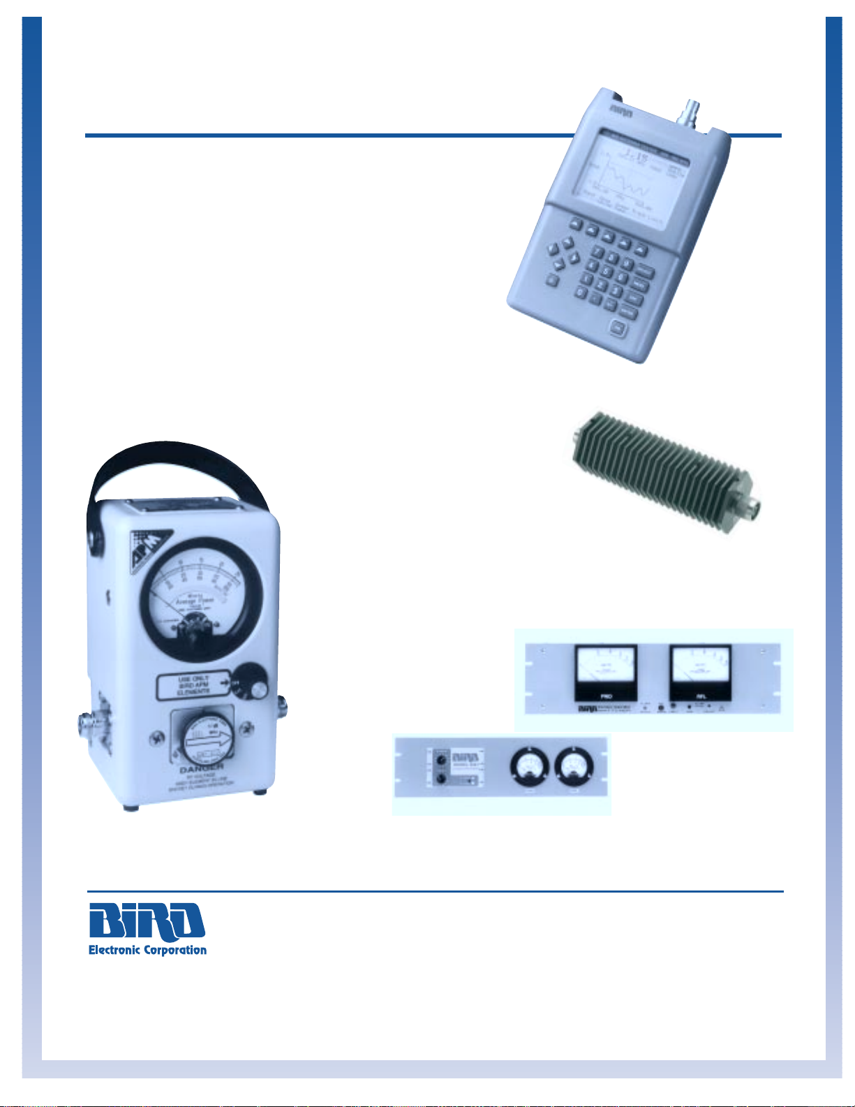
Eastern US Sales Office: Midwestern US Sales Office: Western US Sales Office:
Bird Electronic Corporation Bird Electronic Corporation Bird Electronic Corporation
0303 Aurora Road 50 W. Jefferson Street 621 W. Ojai Avenue Suite F
Cleveland, OH 44139–2794 Franklin, IN 46131 Ojai, CA 93024–3724
Tel: 440–248–1200 Fax: 440–248–5426 Tel: 317–346–6600 Fax: 317–364–6601 Tel: 805–646–7255 Fax: 805–646–0275
Email: sales@bird–electronic.com
Web: http://www.bird–electronic.com
Asia-Pacific Sales Office: European Sales Office:
Bird Electronic Limited Bird Electronic Corporation
37 Tannery Lane, #07-02 Berkhamsted House, 121 High St.
Tannery House Berkhamsted, Herts HP4 2DJ England
Singapore 347790 Tel: 44 1 442 870097 Fax: 44 1 442 870148
Tel: 65–846-8100 Fax: 65–846-1969
© 1998 Bird Electronic Corporation
Catalog No. BEC - GC - 98 Printed in U.S.A.
Advanced
Power Meter
Page 11
HF, VHF, and UHF
Antenna Testers
Page 4
Dry, Coaxial
Terminations
and Attenuators
Pages 42–45
Improved WATTCHER
®
RF Monitor/Alarms
Pages 19, 33
LOOK INSIDE FOR
THESE NEW PRODUCTS…
The name Bird has echoed uncompromising quality throughout the world of RF and microwave communications for
over a half century. Many technicians made their first
RF power measurement with a Model 43 THRULINE
®
Wattmeter and still use this remarkably accurate,
reliable, and rugged instrument today. But you'll also find
many new products throughout this catalog to help you install,
repair, maintain, and operate RF equipment and systems.
Bird's total commitment to research and development, advanced
engineering and quality-driven manufacturing are found in everything
from our new Advanced Power Meter to the latest Bi-directional
Attenuators. And you can confidently purchase any
of these state-of-art products with the assurance
that it will deliver the performance you expect.
At Bird,
new never means unproven. No Bird
design enters production without undergoing
extensive field tests, no instrument leaves our
plant unless it is exactly right.
The evolution and advance of RF technology
and applications into the next millennium
will be mirrored by Bird instruments that
will keep you and your business on the
cutting edge. You can count on it.
A Member of Bird Technologies Group
Multichannel
Power Meters
Page 18
 Loading...