

Page 1

INSTRUCTION BOOK
OPERATING INSTRUCTIONS
TERMALINE®COAXIAL
LOAD RESISTOR
MODEL 8135
Electronic Corporation
Cleveland(Solon)Ohio USA
©Copyright 1996 by Bird Electronic Corporation
Instruction Book Part Number 920-8135 Rev. B
®
Termaline
is a Registered Trademark
of Bird Electronic Corporation
Page 2

Page 3

SAFETY PRECAUTIONS
The following are general safety precautions that are not necessarily related
to any specific part or procedure and do not necessarily appear elsewhere in
this publication. These precautions must be throughly understood and apply
to all phases of operation and maintenance.
KEEP AWAY FROM LIVE CIRCUITS
Operating personnel must at all times observe normal safety regulations. Do
replace components or make adjustments to the inside of the test equipment
with a high voltage supply turned on. To avoid casualties, always disconnect
power.
DO NOT SERVICE OR ADJUST ALONE
Operating personnel must at all times observe normal safety regulations. Do
not attempt to replace parts or disconnect an RF transmission or any other
high voltage line while power is applied. When working with high voltage always have someone present who is capable of rendering aid if necessary. Personnel working with or near high voltage should be familiar with modern
medthods of resuscitation.
SAFETY EARTH GROUND
An uninterruptible earth safety ground must be supplied from the main
power source to test instruments. Grounding one conductor of a two conduc
tor power cable is not sufficient protection. Serious injury or death can occur
if this grounding is not properly supplied.
SHOCK HAZARD
HIGH VOLTAGE is used in the operation of this equipment. DEATH ON
CONTACT may result if personnel fail to observe safety precautions. Learn
the areas containing high voltages in each part of the equipment. Be careful
not to contact high voltage connections when installing or operating this
equipment.
CHEMICAL HAZARD
Solvents used to clean parts are potentially dangerous. Avoid inhalation of
fumes and also prolonged skin contact.
-
i
Page 4

RESUSCITATION
Personnel working with or near high voltages should be familiar with modern
methods of resuscitation.
SAFETY SYMBOLS
WARNING
Warning: Warning notes call attention to a procedure, which if not
correctly performed could result in personal injury.
CAUTION
Caution: Caution notes call attention to a procedure, which if not
correctly performed could result in damage to the instrument.
8135 WARNING STATEMENTS
The following safety warnings appear in the test where there is danger to operating and maintenance personnel and are repeated here for emphasis.
WARNING
When power is in the upper range of the load’s capacity, the radiator
will become hot - care should be used in touching the equipment.
WARNING
Never attempt to disconnect the equipment from the transmission line
while RF power is being applied. Leaking RF energy is a potential
health hazard.
8135 CAUTION STATEMENTS
The following equipment cautions appear in the text whenever the equipment
is in danger of damage and are repeated here for emphasis.
CAUTION
Do not operate this equipment continuously above the rated 150 W.
ii
Page 5

About This Manual
This instruction book covers the models 8135 and 8135A Termaline Coaxial
Load Resistor.
This instruction book is arranged so that essential information on safety is
contained in the front of the book. Reading the Safety Precautions Section be
fore operating the equipment is strongly advised.
The remainder of this Instruction Book is divided into Chapters and Sections.
At the beginning of each chapter a general overview will be given, describing
the contents of that chapter.
OPERATION
First time operators should read Chapter 1 - Introduction and Chapter 3 - Installation, to get an overview of equipment capabilities and how to install it.
An experienced operator can refer to Chapter 4 - Operating Instructions. All
instructions necessary to operate the equipment, are contained in this section.
MAINTENANCE
All personnel should be familiar with preventative maintenance found in
Chapter 5 - Maintenance. If a failure should occur, the troubleshooting sec
tion will aid in isolating and repairing the failure.
-
-
PARTS
For location of major assemblies or parts refer to the parts lists and associ
ated drawings in Chapter 5.
CHANGES TO THIS MANUAL
We have made every effort to ensure this manual is accurate at the time of
publication. If you should discover any errors or if you have suggestions for
improving this manual, please send your comment to our factory. This man
ual may be periodically updated, when inquiring about updates to this man
ual refer to the part number and revision level on the title page.
-
-
-
iii
Page 6

Table Of Contents
Safety Precautions..................i
Warning Statements .....................ii
Caution Statements ......................ii
About This Manual ......................iii
Introduction ....................1
Purpose and Function .....................1
Performance Characteristics and Capabilities ...........1
Dimensions and Weight ....................1
Power and Utility Requirements ................1
Environmental Requirements ..................1
Items Furnished .......................1
Items Required ........................1
Tools and Test Equipment ...................1
Theory of Operation .................3
General ...........................3
Dielectric Coolant and Seal...................3
Installation .....................5
Location ...........................5
Mounting ..........................5
Operating Instructions ................7
Use and Function of Controls..................7
Initial Adjustment ......................7
iv
Page 7

Start Up...........................7
Normal Operation.......................7
Operation Under Abnormal Conditions ..............7
Shutdown Procedures .....................7
Emergency Shutdown .....................8
Maintenance ....................9
Troubleshooting ......................9
Cleaning ........................10
Radiator ..........................10
Inspection ........................10
Oil Leakage .........................10
Cleanliness .........................10
Completeness ........................10
Preventive Maintenance ..................10
RF Assembly Test ....................10
Disassembly .......................11
RF Input Connector Replacement ...............11
Diaphragm and Coolant Oil ..................11
RF Load Resistor Assembly ..................11
Assembly ........................12
RF Input Connector .....................12
Diaphragm and Coolant Oil ..................12
RF Load Resistor Assembly ..................12
Customer Service ......................12
Storage...........................13
Shipment ..........................13
v
Page 8

Bird Model 8135 Termaline Coaxial Load Resistor
Replacement Parts List ....................13
Difference Data Sheet ...............15
VSWR Difference ......................15
Operating position ......................15
vi
Page 9

Chapter 1
Introduction
Purpose and
Function
Performance
Characteristic
Requirements
Requirements
s and
Capabilities
Dimensions
and Weight
Power and
Utility
Enviromental
The Bird Model 8135 TERMALINE Load Resistor is a por
table, general purpose 50 ohm coaxial transmission line ter
mination. It is a self-contained unit requiring no outside
power source or additional equipment. This coaxial load re
sistor provides an accurate, dependable, and practically
non-reflective termination for adjustment, standby, and
testing of transmitters under nonradiating conditions.
The Model 8135 can absorb up to 150 watts continuously
and dissipate it harmlessly as heat over a frequency range
of dc to 4000 MHz. It is designed to show low reflectivity
throughout this range. The VSWR will be 1.1 to 1.0 maxi
mum from dc to 1000 MHz, 1.2 to 1.0 maximum from 1000
to 2500 MHz and 1.3 to 1.0 maximum from 2000 to 4000
MHz.
The Model 8135 is 8-13/16 inches long, 4 inches wide, and
6-7/16 inches high (224 x 102 x 164 mm). It has a weight of
6 lb (2.7 kg) net and a shipping weight of 8 lb (3.6 kg).
Being a passive electronic device, the Model 8135 needs no
outside source or utility service.
The Model 8135 should be used in a dust and vibration-free
environment. The ambient temperature range should be
kept between -40C and +45C (-40F and +113F) for proper
operation. Allow at least 6 inches of clearance around the
load to permit an unimpeded access of convection air cur
rents to the load.
-
-
-
-
-
Items
Furnished
Items
Required
Tools and
Test
Equipment
The RF input connector, located on the front face of the unit,
is a Female N. It is a special “Quick-Change” design permit
ting rapid and easy interchange with other Bird AN type
“QC” connectors. This instruction book is the only other
item provided.
The only other item required is a matching connector on the
coaxial transmission line.
Only simple tools like screwdrivers are needed to disassem
ble the Model 8135. A resistance bridge or ohmmeter with
an accuracy of one percent or better at 50 ohms is useful for
checking the resistance value of the RF section assembly.
-
-
1
Page 10
Bird Model 8135 Termaline Coaxial Load Resistor
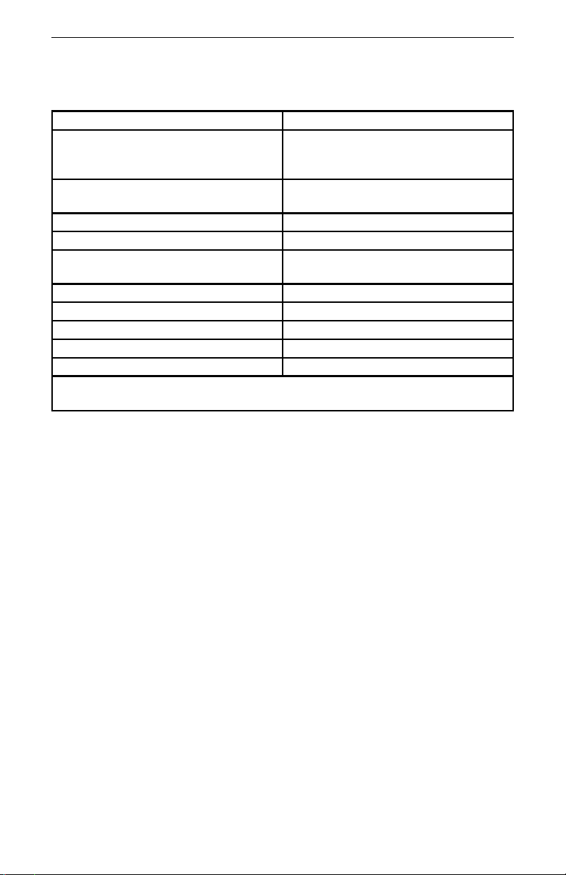
SPECIFICATIONS
Impedance 50 ohms nominal
VSWR 1.1:1.0 maximum dc-1000 MHz
1.2:1.0 maximum 1000-2500 MHz
1.3:1.0 maximum 2500-4000 MHz
Connectors Female N “QC” type
(normally supplied)
Power Range 150 W continuous
Frequency Range DC-4000 MHz
Dimensions 8-13/16"L x 4"W x 6-7/16"H
(224 x 102 x 164 mm)
Ambient Temperature -40C to +45C (-40F to +113F)
Cooling Method Dielectric liquid & air convection
Weight, Nominal 6 lb (2.7 kg)
Operating Position Horizontal only
Finish Grey Powder Coat Paint
NOTE - See Difference Data Sheet, Chapter 6, for additional 8135A
specifications.
2
Page 11

Chapter 2
Theory of Operation
General The Model 8135 TERMALINE Load consists essentially of a
cylindrical film type resistor immersed in dielectric coolant.
The resistor, individually selected for its accuracy, is en
closed in a special tapered housing which provides a linear
reduction in surge impedance directly proportional to the
distance along the load resistor. This produces the uniform,
practically reflectionless line termination over the stated
frequencies of the load.
-
Dielectric
Coolant and
Seal
The coolant oil is chosen for its desirable dielectric proper
ties and thermal characteristics. Cooling of the load is ac
complished by natural fluid and air convection. The
dielectric coolant, 0.1 gallon, carries the electrically gener
ated heat from the resistor to the walls of the cylindrical
cooling tank.
The tank is encased in a set of heavy gauge metal radiating
fins, which are firmly pressed on the cylinder. The heat
from the oil is transferred to the surrounding air by the radiating fins.
A synthetic rubber diaphragm located in the rear dome of
the load allows the coolant to expand as the temperature
rises.
-
-
-
3
Page 12

Bird Model 8135 Termaline Coaxial Load Resistor
4
Page 13

Chapter 3
Installation
Location Free air circulation around the Model 8135 TERMALINE
Load is essential. Keep the load in the clear, and do not
place it near heated surfaces. The Model 8135 should have
at least a 6 inch clearance on all sides. Keep the space above
the unit unobstructed for good air circulation. This load is to
be mounted only in a horizontal position to insure that the
load resistor will always be immersed in the coolant.
Mounting The Model 8135 may be fastened to a work or test bench. To
do this, remove the four rubber bumpers from the bottom of
the radiator. These bumpers are fastened to the corners of
the bottom radiator brace by 8-32 studs which are set per
manently into the rubber feet. The bumpers unscrew easily
by hand. The holes are threaded for 8-32 screws. The fasteners must be placed up through the bench and into the load.
These holes are ona3x7inch rectangle (76 x 178 mm).
-
5
Page 14

Bird Model 8135 Termaline Coaxial Load Resistor
6
Page 15
Chapter 4
Operating Instructions
Use and
Function of
Controls
Initial
Adjustment
Start Up Connect the Model 8135 TERMALINE Load to the trans
The Model 8135 is a passive electronic device and therefore
has no controls to operate.
No adjustments or setting are required.
mitting equipment under test with 50 ohm coaxial cable
such as RG213/U or equal, and a Male N type plug
(UG-21E/U or equal) which mates with the RF Input con
nector of the load. After the transmitter has been connected
to the load, proceed according to the transmitter manufac
turer’s instructions. When reconnecting the antenna, it may
become necessary to readjust the transmitter due to possible differences in VSWR.
Normal
Operation
Being a passive device, the Model 8135 will function without
an operator in attendance provided its stated performance
limits are not exceeded. WARNING
When power is in the upper range of the load’s capacity, the
radiator will become hot - care should be used in touching
the equipment.
CAUTION
Do not operate this equipment continuously
above the rated 150 W.
-
-
-
Operation
Under
Abnormal
Conditions
Sutdown
Procedures
The Model 8135 can be subjected to moderate overloads for
short periods of time, providing a sufficient amount of time
is allowed between intervals for adequate cooling. An exam
ple would be 250 watts for a maximum of 5 minutes, allow
ing at least a 20 minute interval for cooling between power
applications.
There is no way to turn off the Model 8135; power must be
shut off at the RF source instead.
-
-
7
Page 16
Bird Model 8135 Termaline Coaxial Load Resistor
Emergency
Shutdown
Power must be shut off from the RF source as in the above
procedure.
WARNING
Never attempt to disconnect the equipment from the
transmission line while RF power is being applied.
Leaking RF energy is a potential health hazard.
8
Page 17
Chapter 5
Troubleshooting
Maintenance
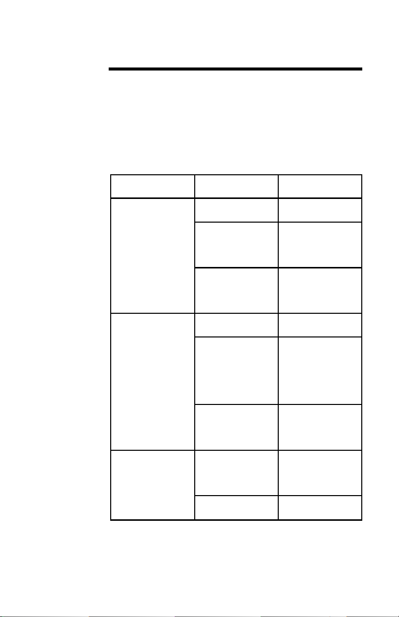
Table 1
Troubleshootin
For corrections requiring repair or replacement of compo
nents, refer to the appropriate section for your specific
model.
g
Lakage of cool
ant oil around
clamping band or
radiator housing
Overheating of
the radiator
High and low dc
resistance values
per para RF As
sembly Test
PROBLEM POSSIBLE
CAUSE
Clamping bands
not tight
Faulty O-Ring
(front)
Faulty diaphragm (rear)
Transmitter
power too high
Coolant oil level
too low
Faulty RF sec
tion assembly
Faulty RF input
connector
-
Loose RF input
connector
-
REMEDY
Tighten slightly
with screwdriver
Replace per para
Disassembly, RF
Load Resistor
Assembly
Replace per para
Disassembly, Diaphragm and
Coolant Oil
Reduce transmitter power
Add more coolant
oil to the radiator per para Dis
assembly,
Diaphragm and
Coolant Oil
Replace per para
Disassembly, RF
Load Resistor
Assembly
Replace per para
Disassembly, RF
Input Connector
Replacement
Tighten with a
screwdriver
-
-
9
Page 18

Bird Model 8135 Termaline Coaxial Load Resistor
Cleaning
Radiator The principle maintenance required by the operator will be
the cleaning of the radiator fins. Keep the radiator of the
Model 8135 Termaline Load clean and free of dust. Wipe
away the accumulated dust and grime with a soft clean
cloth. If the insulator or metallic contact surfaces of the RF
input connector should become dirty or grimy, clean care
fully with a soft clean cloth. Use self-drying, spray or aero
sol contact cleaner that leaves no residue on the inaccessible
portions of the connector.
Inspection
-
-
Periodic Inspection - with the rugged and simple construc
tion of the Model 8135 Termaline Load, periodic inspection
will be necessary at only about six month intervals. Inspec
tion should include the items listed below:
Oil Leakage Check for coolant oil seepage around the radiator tank, and
particularly at the front and back around the underside of
the clamping bands. See paragraph 5.1, Troubleshooting, if
leakage is observed. Check tightness of the clamping bands,
both front and back.
Cleanliness Check for cleanliness of the radiator fins and the RF connec-
tor. Proceed as in paragraph Cleaning.
Completenes
Inspect the Model 8135 Termaline Load for completeness
s
and general condition of the equipment.
Preventive Maintenance
Most of the preventive maintenance procedures are covered
in the previous paragraph 5.5, Inspection. If any portions of
the radiator are corroded or rusted, clean the area carefully
with a fine flint sandpaper, and touch up the grey enamel.
RF Assembly Test
DC Resistance - Check the condition of the load resistor by
accurate measurement of the dc resistance between the in
ner and outer conductors of the RF input connector. Use a
resistance bridge or ohmmeter with an accuracy of one per
cent or better at 50 ohms for this purpose. The measured re
sistance should be nominal 50 ohms. For greater accuracy,
the resistance of the load should be carefully checked prior
to use at ambient room temperature. This resistance value
should be recorded and used as a reference. Subsequent re
sistance measurements should not deviate more than two
percent from this value.
10
-
-
-
-
-
-
Page 19

Maintenance
Disassembly
There are no special techniques required for the repair or
replacement of components in the Model 8135 TERMALINE
Load. A screwdriver is the only tool needed. The paragraphs
below outline component removal.
RF Input
Connector
Replacement
Diaphragm
and Coolant
Oil
The input connector is a patented “Quick-Change” design
which permits easy interchange with the use of only a
screwdriver. This process does not interfere with the essen
tial coaxial continuity of the load resistor RF input or the
coolant oil seal. For replacement, proceed as follows:
1. Remove the four 8-32 x 5/16 inch round head
machine screws from the corners of the RF con
-
nector.
2. Pull the connector straight out of its socket.
Remove the diaphragm to replace or examine the coolant
oil. Replacement of the diaphragm and coolant oil are outlined in the following steps:
1. Stand the load vertically, with the back end up.
2. Loosen the clamp screw until clamping band is
released.
3. Remove the diaphragm cover and lift diaphragm
from back end of radiator tank. If the diaphragm
is no longer pliable or shows signs of surface
cracks, replace it.
4. The coolant oil level should be about one inch be
low the top of the radiator cylinder. If the oil ap
pears to be contaminated, replace it.
-
-
-
RF Load
Resistor
Assembly
To replace the load resistor assembly, proceed as follows:
1. Stand load vertically, connector end up.
2. Loosen clamp screw until clamping band is re
-
leased.
3. Lift load resistor assembly straight up out of the
cylinder, allowing the coolant to drip back into
cylinder.
4. Inspect the O-Ring seal which is located just in
side the mounting flange of the resistor assembly.
-
11
Page 20

Bird Model 8135 Termaline Coaxial Load Resistor
RF Input
Connector
Diaphragm
and Coolant
Oil
RF Load
Resistor
Assembly
Customer
Service
DO NOT reuse the O-Ring if it is no longer pli
-
able or shows signs of surface cracks.
ASSEMBLY
Reverse the procedure in the RF Input Connector Replace
ment paragraph to install a new connector. Be sure that the
projecting center contact pin on the connector is carefully
engaged and properly seated with the mating socket of the
load resistor input.
To reassemble, reverse the procedure in the Diaphragm and
Coolant oil paragraph.
To replace the load assembly, reverse the procedure in the
RF Load Resistor Assembly paragraph.
Any maintenance or service procedure beyond the scope of
those provided in this section should be referred to a qualified service center. Bird Electronic Corporation maintains
complete repair and calibration facilities.
Service Group
U.S.A. Sales and Manufacturing
Bird Electronic Corporation
30303 Aurora Road
Cleveland (Solon), Ohio 44139-2794
Phone: (440) 248-1200
Fax: (440) 248-5426
-
12
Sales Offices
For the location of the sales office nearest you, give us a call
or visit our Web site at:
http://www.bird-electronic.com
Page 21
Maintenance
Storage No special preparations for storage are necessary other than
covering the load to keep it dust free. Store in a dry and
dust-free environment. Keeping the ambient temperature
within the -40C to +45C (-40F to +113F) working range is
preferable.
Shipment Wrap the RF connector with padding and tape it securely.
Pack and brace the Model 8135 in a suitable shipping con
tainer. A corrugated paper box should suffice. It is not nec
essary to remove the dielectric coolant before shipping.
-
-
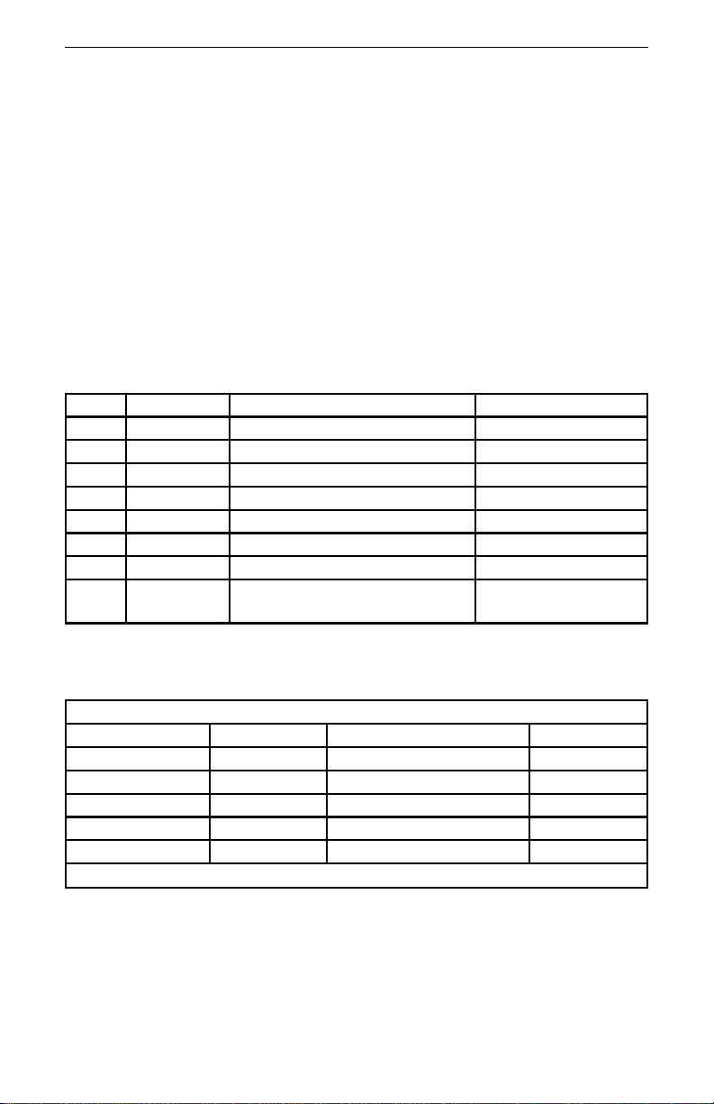
Replacement
Parts List
Model 8135
Item Qty. Description Part Number
1 1 RF load resistor assembly
2 1 Radiator
8130-015
2400-025
3 1 O-Ring seal
4 2 Clamping band assembly
5 1 Diaphragm
6 1 Diaphragm cap
7 1 Connector
8 0.1 gallon
Coolant Oil
(0.4 liters)
(1 pint container)
7500-254
2400-015
2400-050
*See Below
*Available QC Type Connectors
N-Female
N-Male
HN-Female
HN-Male
LC-Female
LC-Male
4240-062
4240-063
4240-268
4240-278
4240-031
4240-025
LT-Female
LT-Male
C-Female
C-Male
UHF-Female (SO-239)
UHF-Male (PL-259)
4240-018
4240-012
4240-100
4240-110
4240-050
4240-179
7/8" EIA Air Line 4240-002
5-229
5-030-1
13
Page 22

Bird Model 8135 Termaline Coaxial Load Resistor
14
Page 23

Chapter 6
Difference Data Sheet
MODEL 8135A TERMALINE LOAD RESISTOR
The Model 8135A is identical to the Model 8135 electrically
and physically. It has, however, a special RF section which
provides special peak power handling capabilities. It will
handle up to 35 kW peak power with a pulse width of one
microsecond. For further information on peak power rat
ings, contact the factory.
When ordering a new RF section for the Model 8135A, order
part number 8130-022. All other part numbers remain the
same.
-
VSWR
Difference
Operating
Position
Less than 1.1 to 1.0 maximum dc to 1000 MHz. Less than
1.2 to 1.0 maximum 1000 to 4000 MHz.
Horizontal or vertical with connector end down.
15
Page 24

Limited Warranty
All products manufactured by Seller are warranted to be free from defects in
material and workmanship for a period of one (1) year, unless otherwise spec
ified, from date of shipment and to conform to applicable specifications, draw
ings, blueprints and/or samples. Seller’s sole obligation under these
warranties shall be to issue credit, repair or replace any item or part thereof
which is proved to be other than as warranted; no allowance shall be made
for any labor charges of Buyer for replacement of parts, adjustment or re
pairs, or any other work, unless such charges are authorized in advance by
Seller.
If Seller’s products are claimed to be defective in material or workmanship or
not to conform to specifications, drawings, blueprints and/or samples, Seller
shall, upon prompt notice thereof, either examine the products where they
are located or issue shipping instructions for return to Seller (transporta
tion-charges prepaid by Buyer). In the event any of our products are proved
to be other than as warranted, transportation costs (cheapest way) to and
from Seller’s plant, will be borne by Seller and reimbursement or credit will
be made for amounts so expended by Buyer. Every such claim for breach of
these warranties shall be deemed to be waived by Buyer unless made in writing within ten (10) days from the date of discovery of the defect.
The above warranties shall not extend to any products or parts thereof which
have been subjected to any misuse or neglect, damaged by accident, rendered
defective by reason of improper installation or by the performance of repairs
or alterations outside of our plant, and shall not apply to any goods or parts
thereof furnished by Buyer or acquired from others at Buyer’s request and/or
to Buyer’s specifications. In addition, Seller’s warranties do not extend to the
failure of tubes, transistors, fuses and batteries, or to other equipment and
parts manufactured by others except to the extent of the original manufac
turer’s warranty to Seller.
-
-
-
-
-
The obligations under the foregoing warranties are limited to the precise
terms thereof. These warranties provide exclusive remedies, expressly in lieu
of all other remedies including claims for special or consequential damages.
SELLER NEITHER MAKES NOR ASSUMES ANY OTHER WARRANTY
WHATSOEVER, WHETHER EXPRESS, STATUTORY, OR IMPLIED, IN
CLUDING WARRANTIES OF MERCHANTABILITY AND FITNESS, AND
NO PERSON IS AUTHORIZED TO ASSUME FOR SELLER ANY OBLIGA
TION OR LIABILITY NOT STRICTLY IN ACCORDANCE WITH THE
FOREGOING.
16
-
-
Page 25

DECLARATION OF CONFORMITY
Manufacturer: Bird Electronic Corporation
Product: TERMALINE RF COAXIAL LOAD RESISTOR
The undersigned hereby declares, on behalf of Bird Electronic Corporation of
Cleveland, Ohio, that the above-referenced product, to which this declaration relates, is
in conformity with the provisions of the following standards;
1. European Standard EN 61010-1:1993 - Safety, Group II.
This standard is in accordance with Council Directive 73/23/EEC and 93/68/EEC.
The technical documentation file required by this directive is maintained at the corporate
headquarters of Bird Electronic Corporation, 30303 Aurora Road, Cleveland, Ohio.
30303 Aurora Road
Cleveland, Ohio 44139-2794
Models: 8135 8135A 8135-075
Ken DeVore
Metrology/QA Manager
Bird Electronic Corporation
17
 Loading...