

Page 1

INSTRUCTION BOOK
THRULINE® RF POWER METER MODEL 4421
AND
THRULINE® DIRECTIONAL RF POWER SENSORS
4020 SERIES, 4027A SERIES,
4027F SERIES, AND 4028 SERIES
Bird® Electronic Corporation
30303 Aurora Road
Cleveland (Solon), Ohio 44139
Sales & Technical Support: 440-248-1200
866-695-4569 toll free
©
Copyright 2005
Instruction Book Part Number 920-4421 Rev Q
by Bird Electronic Corporation
Thruline® is a Registered Trademark
of Bird Electronic Corporation
Page 2

This page intentionally left blankiSafety Precautions
Page 3

The following are general safety precautions that are not necessarily
related to any specific part or procedure and do not necessarily appear
elsewhere in this publication. These precautions must be thoroughly
understood and apply to all phases of operation and maintenance.
Keep Away From Live Circuits
Operating personnel must at all times observe normal safety regulations.
Do not replace components or make adjustments inside the equipment
with high voltage turned on. To avoid casualties, always remove power.
Shock Hazard
Do not attempt to remove the RF transmission line while RF power is
present.
Do Not Service or Adjust Alone
Under no circumstances should any person reach into an enclosure for the
purpose of service or adjustment of equipment except in the presence of
someone who is capable of rendering aid.
Safety Earth Ground
An uninterruptible earth safety ground must be supplied from the main
power source to test instruments. Grounding one conductor of a two
conductor power cable is not sufficient
can occur if this grounding is not properly supplied.
Chemical Hazard
Dry cleaning solvents for cleaning parts may be potentially dangerous.
Avoid inhalation of fumes or prolonged contact with skin.
Resuscitation
Personnel working with or near high voltages should be familiar with
modern methods of resuscitation.
protection. Serious injury or death
Page 4

Bird 4421 RF Power Meter
Safety Symbols
Warning notes call attention to a procedure which, if not correctly
Caution notes call attention to a procedure which, if not correctly
performed, could result in damage to the instrument.
The caution symbol appears on the equipment indicating there
is important information in the instruction manual regarding
that particular area.
NOTE: Calls attention to supplemental information.
Warning Statements
WARNING
performed, could result in personal injury.
CAUTION
The following safety
operating and maintenance personnel an
warnings appear in the text
d are repeated here for emphasis.
where there is danger to
WARNING
Never attempt to connect or disconnect RF equipment from the
transmission line while RF power is being applied.
Leaking RF energy is a potential health hazard.
WARNING
Heavy load. Do not attempt to lift unaided.
WARNING
To avoid personal injury, disconnect th
performing any maintenance, including fuse replacement or changing the
line voltage setting.
e power cord from the ac line before
WARNING
Exposed ac line voltage (115 V
power cord from the ac line before
to comply may result in seve
ii
AC or 230 VAC). Disconnect the
replacing the batt
eries. Failure
re electrical shock or death.
Page 5

WARNING
To avoid personal injury, disconnect th
performing any maintenance, including fuse replacement or changing the
line voltage setting.
CAUTION
During remote operation, pe
service request line. Failure
could result in
e power cord from the ac line before
riodically monitor the bus
to detect a service request
equipment damage.
Caution Statements
The following equipment cautions appear in the text whenever the
equipment is in danger of damage and are repeated here for emphasis.
CAUTION
The interface module contains electrostatic discharge (ESD)
sensitive components. Failure to observe ESD precautions can
cause permanent damage.
CAUTION
ill invalidate calibration data,
and may reduce the maximum power rating of the unit.
CAUTION
The Bird 4421 must be powered off when connecting or
disconnecting the power sensor from the power meter.
CAUTION
Do not use the power sensor with a load VSWR greater then 2:1.
Damage to the power meter, power sensor, or the
RF power source could occur.
CAUTION
During remote operation, periodically monitor the bus
service request line. Failure to detect a service request
could result in equipment damage.
iii
Page 6

Bird 4421 RF Power Meter
Due to the complexity of the Bird Power Sensor, field repairs
beyond general maintenance should not be attempted.
Removal or disturbance of the power sensor cover can result in
Failure to install the properly rated fuse may result in equipment
Safety Statements
USAGE
ANY USE OF THIS INSTRUMENT IN A MANNER NOT
SPECIFIED BY THE MANUFACTURER MAY IMPAIR THE
USO
CAUTION
cancellation of lifetime warranty.
CAUTION
damage or nuisance failures.
EL USO DE ESTE INSTRUMENTO DE MANERA NO ESPECIFICADA
POR EL FABRICANTE, PUEDE ANULAR LA PROTECCIÓN DE
SEGURIDAD DEL INSTRUMENTO.
iv
Page 7

BENUTZUNG
WIRD DAS GERÄT AUF ANDERE WEISE VERWENDET ALS VOM
HERSTELLER BESCHRIEBEN, KANN DIE GERÄTESICHERHEIT
BEEINTRÄCHTIGT WERDEN.
UTILISATION
TOUTE UTILISATION DE CET
EXPLICITEMENT PRÉVUE PAR LE FABRICANT PEUT
ENDOMMAGER LE DISPOSITIF DE PROTECTION DE
IMPRIEGO
QUALORA QUESTO STRUMENTO VENISSE UTILIZZATO IN MODO
DIVERSO DA COME SPECIFICATO DAL PRODUTTORE LA
PROZIONE DI SICUREZZA POTREBBE VENIRNE COMPROMESSA.
SERVICE
SERVICING INSTRUCTIONS ARE FOR USE BY SERVICE-
TRAINED PERSONNEL ONLY. TO AVOID DANGEROUS
ELECTRIC SHOCK, DO NOT PERFORM ANY SERVICING UNLESS
QUALIFIED TO DO SO.
SERVICIO
LAS INSTRUCCIONES DE SERVICIO SON PARA USO EXCLUSIVO
DEL PERSONAL DE SERVICIO CAPACITADO. PARA EVITAR EL
PELIGRO DE DESCARGAS ELÉCTRICAS, NO REALICE NINGÚN
SERVICIO A MENOS QUE ESTÉ CAPACITADO PARA HACERIO.
WARTUNG
ANWEISUNGEN FÜR DIE WARTUNG DES GERÄTES GELTEN NUR
FÜR GESCHULTES FACHPERSONAL.
ZUR VERMEIDUNG GEFÄHRLICHE, ELEKTRISCHE SCHOCKS, SID
WARTUNGSARBEITEN AUSSCHLIEßLICH VON QUALIFIZIERTEM
SERVICEPERSONAL DURCHZUFÜHREN.
ENTRENTIEN
RÉSERVÉ AU PERSONNEL FORMÉ AUX OPÉRATIONS
ÉTÉ QUALIFIÉ POUR CE FAIRE.
ASSISTENZA TECNICA
ESCLUSIVAMENTE PER IL PERSONALE OPPORTUNAMENTE
ADDESTRATO. PER EVITARE PERICOLOSE SCOSSE ELETTRICHE
NON EFFETTUARRE ALCUNA RIPARAZIONE A MENO CHE
QUALIFICATI A FARLA.
v
Page 8

Bird 4421 RF Power Meter
UNITS ARE EQUIPPED WITH
RECHAREABLE BATTERIES.
THESE ARE TO BE REPLACED BY AUTHORIZED SERVICE
PERSONNEL ONLY!!!
LAS UNIDADES VIENEN EQUIPADAS CON BATERIAS
RECARGABLES. ¡¡¡Y SOLAMENTE EL PERSONAL DE SERVICIO
AUTORIZADO PUEDE REEMPLAZARLAS!!!
GERÄTE SIND MIT WIEDER AUFLADBAREN BATTERIEN
BESTÜCKT. BATTERIEN SIND NUR VON QUALIFIZIERTEM
SERICE PERSONAL AUSZUWECHSELN!!!
CES DISPOSITIFS SONT ÉQUIPÉS DE BATTERIES
AUTORISÉ EST HABILITÉ À LES REMPLACER !
LE UNITÀ SONO DOTATE DI BATTERIE RICARICABILI, CHE
DEVONO DA COME SPECIFICATO DAL PRODUTTORE LA
PROTEZIONE DI SICUREZZA POTREBBE VENIRNE
COMPROMESSA.
BE SURE THE 115/230V AC VOLTAGE SELECTOR IS SET
TO THE PROPER LINE VOLTAGE, AND THE CORRECT AC
LINE FUSE IS INSTALLED BEFORE AC POWER IS
APPLIED.
BIEN RÉGLÉ POUR LA TENSION DU RÉSEAU ET QUE LE FUSIBLE
DE LIGNE C.A. CORRECT EST EN PLACE AVANT DE METTRE SOUS
TENSION C.A.
CERCIORESE QUE EL SELECTOR DE VOLTAJ E DE 115/230V CA
ESTE COLOCADO A LA LINEA DE VOLTAJE APROPIADA Y QUE EL
FUSIBLE ESTE INSTALADO A LA LINEA CA ANTES DE APLICAR
LA CORRIENTE ALTERNA.
VOR EINSCHALTEN DER WECHSELSTROMZUFUHR
SICHERSTELLEN, DASS DER 115/230V WECHSELSPANNUNGSSELEKTOR AUF DIE VORSCHRIFTSMÄSSIGE
LEITUNGSSPANNUNG EINGESTELLT UND DIE RICHTIGE
WECHSELSTROM-HAUPTSICHERUNG EINGESETZT IST.
PRIMA DI EROGARE CORRENTE, ASSICURARSI CHE IL
SELETTORE DI VOLTAGGIO 115/230 V.C.A. SIA REGOLATO
CORRETTAMENTE E CHE IL FUSIBLE ADATTO ALLA LINEA DI
ALIMENTAZIONE C.A. SIA INSTALLATO.
vi
Page 9

About This Manual
This manual covers the Bird 4421 RF Power Meter and the sensors it
works with. Specific models include:
Power Meter
4020 Series
Sensors
4027A Series
Sensors
4027F Series
Sensors
4028A Series
Sensors
4028B Series
Sensors
4028C Series
Sensors
4421
4021 4022 4024 4025
4027A250K 4027A400K 4027A800K 4027A2M
4027A4M 4027A10M 4027A12M 4027A25M
4027A35M 4027A60M 4027A100M 4027A150M
4027F2M 4027F10M 4027F60M
4028A250K 4028A400K 4028A2M 4028A3M
4028A4M 4028A10M 4028A25M
4028B10M
4028C10M
This instruction book is arranged so that essential safety information
appears in the front of the book. Reading the Safety Precautions before
operating the equipment is strongly advised.
The remainder of this manual is divided into Chapters and Sections. At
the start of each chapter, a general overview describes its contents.
Operation
Installation to get an overview of eq
uipment capabilities and installation.
Experienced operators can refer to
All instructions necessary to manually operate the equipment appear in
this chapter. If the power meter is equipped with a IEEE-488 GPIB
488 GPIB Interface. For the RS-232
Maintenance
You should be familiar with preventative maintenance found in Chapter
will aid in isolating and repairing the failure. A list of replacement parts
with part numbers is also in this chapter.
vii
Page 10

Bird 4421 RF Power Meter
Changes To This Manual
We have made every effort to ensure this manual is accurate. If you
should discover any errors, or if you have suggestions for improving this
manual, please send your comments to our factory. This manual may be
periodically updated. When inquiring about updates to this manual refer
to the part number and revision level on the title page.
viii
Page 11

Table of Contents
Intr oduction . . . . . . . . . . . . . . . . . . . . . . . . . . . . . . . . . . . . . . . . . . . . . . . . . . . . . . . . . . . 1
Power Meter . . . . . . . . . . . . . . . . . . . . . . . . . . . . . . . . . . . . . . . . . . . . . . . . . . . . . . . . . . . 1
Items Supplied . . . . . . . . . . . . . . . . . . . . . . . . . . . . . . . . . . . . . . . . . . . . . . . . . . . . . . . . . 1
Optional Accessories . . . . . . . . . . . . . . . . . . . . . . . . . . . . . . . . . . . . . . . . . . . . . . . . . . . . 1
Power Sensors . . . . . . . . . . . . . . . . . . . . . . . . . . . . . . . . . . . . . . . . . . . . . . . . . . . . . . . . . 2
4020 Series . . . . . . . . . . . . . . . . . . . . . . . . . . . . . . . . . . . . . . . . . . . . . . . . . . . . . . . . 2
4027A Series . . . . . . . . . . . . . . . . . . . . . . . . . . . . . . . . . . . . . . . . . . . . . . . . . . . . . . . 3
4027F Series . . . . . . . . . . . . . . . . . . . . . . . . . . . . . . . . . . . . . . . . . . . . . . . . . . . . . . . 3
4028 Series . . . . . . . . . . . . . . . . . . . . . . . . . . . . . . . . . . . . . . . . . . . . . . . . . . . . . . . . 3
Frequency and Power Ranges . . . . . . . . . . . . . . . . . . . . . . . . . . . . . . . . . . . . . . . . . . . . . 5
4020 Series . . . . . . . . . . . . . . . . . . . . . . . . . . . . . . . . . . . . . . . . . . . . . . . . . . . . . . . . 5
4027A Series . . . . . . . . . . . . . . . . . . . . . . . . . . . . . . . . . . . . . . . . . . . . . . . . . . . . . . . 5
4027F Series . . . . . . . . . . . . . . . . . . . . . . . . . . . . . . . . . . . . . . . . . . . . . . . . . . . . . . . 5
4028 Series . . . . . . . . . . . . . . . . . . . . . . . . . . . . . . . . . . . . . . . . . . . . . . . . . . . . . . . . 6
Insta llation . . . . . . . . . . . . . . . . . . . . . . . . . . . . . . . . . . . . . . . . . . . . . . . . . . . . . . . . . . . . 7
Sensor Connection . . . . . . . . . . . . . . . . . . . . . . . . . . . . . . . . . . . . . . . . . . . . . . . . . . . . . . 7
RF Line Connection . . . . . . . . . . . . . . . . . . . . . . . . . . . . . . . . . . . . . . . . . . . . . . . . . . . . . 7
Panel Mounting the 4421 Power Meter . . . . . . . . . . . . . . . . . . . . . . . . . . . . . . . . . . . . . 8
Handle Operation . . . . . . . . . . . . . . . . . . . . . . . . . . . . . . . . . . . . . . . . . . . . . . . . . . . . . . 9
115/230V AC Input Power . . . . . . . . . . . . . . . . . . . . . . . . . . . . . . . . . . . . . . . . . . . . . . . . 9
AC Line Connectors . . . . . . . . . . . . . . . . . . . . . . . . . . . . . . . . . . . . . . . . . . . . . . . . . 9
Operating Inst ructions . . . . . . . . . . . . . . . . . . . . . . . . . . . . . . . . . . . . . . . . . . . . . . . . . . 11
Push Button Functions . . . . . . . . . . . . . . . . . . .
Error Codes . . . . . . . . . . . . . . . . . . . . . . . . . . . . . . . . . . . . . . . . . . . . . . . . . . . . . . . . . . 12
Audible Warning . . . . . . . . . . . . . . . . . . . . . . . . . . . . . . . . . . . . . . . . . . . . . . . . . . . . . . 12
IEEE -488 GPIB Interface. . . . . . . . . . . . . . . . . . . . . . . . . . . . . . . . . . . . . . . . . . . . . . . . 13
Description . . . . . . . . . . . . . . . . . . . . . . . . . . . . . . . . . . . . . . . . . . . . . . . . . . . . . . . . . . . 13
Cable Connector . . . . . . . . . . . . . . . . . . . . . . . . . . . . . . . . . . . . . . . . . . . . . . . . . . . 13
Interface Capabilities . . . . . . . . . . . . . . . . . . . . . . . . . . . . . . . . . . . . . . . . . . . . . . . 14
Indicators . . . . . . . . . . . . . . . . . . . . . . . . . . . . . . . . . . . . . . . . . . . . . . . . . . . . . . . . . 14
Setup . . . . . . . . . . . . . . . . . . . . . . . . . . . . . . . . . . . . . . . . . . . . . . . . . . . . . . . . . . . . . . . 15
Dip Switch . . . . . . . . . . . . . . . . . . . . . . . . . . . . . . . . . . . . . . . . . . . . . . . . . . . . . . . . 15
Talker-Only Mode . . . . . . . . . . . . . . . . . . . . . . . . . . . . . . . . . . . . . . . . . . . . . . . . . . 15
Command Syntax . . . . . . . . . . . . . . . . . . . . . . . . . . . . . . . . . . . . . . . . . . . . . . . . . . . . . 15
General Bus Commands . . . . . . . . . . . . . . . . . . . . . . . . . . . . . . . . . . . . . . . . . . . . . . . . 16
Device Dependent Commands . . . . . . . . . . . . . . . . . . . . . . . . . . . . . . . . . . . . . . . . . . . 20
RS-232 Interface . . . . . . . . . . . . . . . . . . . . . . . . . . . . . . . . . . . . . . . . . . . . . . . . . . . . . . .
Description . . . . . . . . . . . . . . . . . . . . . . . . . . . . . . . . . . . . . . . . . . . . . . . . . . . . . . . . . . . 29
Cable Connector . . . . . . . . . . . . . . . . . . . . . . . . . . . . . . . . . . . . . . . . . . . . . . . . . . . 29
Indicators . . . . . . . . . . . . . . . . . . . . . . . . . . . . . . . . . . . . . . . . . . . . . . . . . . . . . . . . . 29
Setup . . . . . . . . . . . . . . . . . . . . . . . . . . . . . . . . . . . . . . . . . . . . . . . . . . . . . . . . . . . . . . . 30
DIP Switch . . . . . . . . . . . . . . . . . . . . . . . . . . . . . . . . . . . . . . . . . . . . . . . . . . . . . . . . 30
Auto Baud . . . . . . . . . . . . . . . . . . . . . . . . . . . . . . . . . . . . . . . . . . . . . . . . . . . . . . . . 31
Talker-Only Mode . . . . . . . . . . . . . . . . . . . . . . . . . . . . . . . . . . . . . . . . . . . . . . . . . . 31
Command Syntax . . . . . . . . . . . . . . . . . . . . . . . . . . . . . . . . . . . . . . . . . . . . . . . . . . . . . 31
General Bus Commands . . . . . . . . . . . . . . . . . . . . . . . . . . . . . . . . . . . . . . . . . . . . . . . . 32
. . . . . . . . . . . . . . . . . . . . . . . . . . . . . . 11
29
ix
Page 12

Device Dependent Commands . . . . . . . . . . . . . . . . . . . . . . . . . . . . . . . . . . . . . . . . . . . . 34
Ma intenan ce . . . . . . . . . . . . . . . . . . . . . . . . . . . . . . . . . . . . . . . . . . . . . . . . . . . . . . . . . . 41
Cleaning . . . . . . . . . . . . . . . . . . . . . . . . . . . . . . . . . . . . . . . . . . . . . . . . . . . . . . . . . . . . .41
Troubleshooting . . . . . . . . . . . . . . . . . . . . . . . . . . . . . . . . . . . . . . . . . . . . . . . . . . . . . . .41
Functional Test . . . . . . . . . . . . . . . . . . . . . . . . . . . . . . . . . . . . . . . . . . . . . . . . . . . .43
Push Button Test . . . . . . . . . . . . . . . . . . . . . . . . . . . . . . . . . . . . . . . . . . . . . . . . . . .44
Repair . . . . . . . . . . . . . . . . . . . . . . . . . . . . . . . . . . . . . . . . . . . . . . . . . . . . . . . . . . . . . . .45
Front Panel (Cal Cart only) . . . . . . . . . . . . . . . . . . . . . . . . . . . . . . . . . . . . . . . . . .45
Cord Reel (Cal Cart only) . . . . . . . . . . . . . . . . . . . . . . . . . . . . . . . . . . . . . . . . . . . .45
Replacing Fuses . . . . . . . . . . . . . . . . . . . . . . . . . . . . . . . . . . . . . . . . . . . . . . . . . . . .46
Replacing Batteries . . . . . . . . . . . . . . . . . . . . . . . . . . . . . . . . . . . . . . . . . . . . . . . . . 47
Power Sensor (Cal Cart only) . . . . . . . . . . . . . . . . . . . . . . . . . . . . . . . . . . . . . . . . . 48
Load . . . . . . . . . . . . . . . . . . . . . . . . . . . . . . . . . . . . . . . . . . . . . . . . . . . . . . . . . . . . .
49
Casters . . . . . . . . . . . . . . . . . . . . . . . . . . . . . . . . . . . . . . . . . . . . . . . . . . . . . . . . . . .49
Handle . . . . . . . . . . . . . . . . . . . . . . . . . . . . . . . . . . . . . . . . . . . . . . . . . . . . . . . . . . .49
Storage and Shipment (Cal Cart only)
. . . . . . . . . . . . . . . . . . . . . . . . . . . . . . . . . . . . .49
Specifications, Cal Cart . . . . . . . . . . . . . . . . . . . . . . . . . . . . . . . . . . . . . . . . . . . . . . . . . 50
Specifications, 4421 Power Meter . . . . . . . . . . . . . . . . . . . . . . . . . . . . . . . . . . . . . . . . .51
Specifications, Power Sensors . . . . . . . . . . . . . . . . . . . . . . . . . . . . . . . . . . . . . . . . . . . . 52
Specifications, RS-232 Interface . . . . . . . . . . . . .
. . . . . . . . . . . . . . . . . . . . . . . . . . . . .56
Specifications, IEEE-488 GPIB Interface . . . . . . . . . . . . . . . . . . . . . . . . . . . . . . . . . . .57
Replacement Parts . . . . . . . . . . . . . . . . . . . . . . . . . . . . . . . . . . . . . . . . . . . . . . . . . . . . .58
Customer Service . . . . . . . . . . . . . . . . . . . . . . . . . . . . . . . . . . . . . . . . . . . . . . . . . . . . . . 59
x
Page 13

Power Meter
Chapter 1
Introduction
The Bird 4421 RF Power Meter is one
surement system. An RF power sensor su
The system can be contro
through an RS-232 connection or a GPIB-488 connection.
Items Supplied
Bird 4421 RF Power Meter
AC Power Cord
Sensor Cable
Instruction Manual
Optional Accessories
Panel Mount Kit (P/N 4421-250):
standard 19" panel for rack mount applications.
Null Modem Kit (P/N 4380-250):
the 4421 to be remotely controlled by
arrangements. Requires an RS-232 interface module.
component of a complete RF power mea-
ch as a Bird 4021 is also required.
lled with the front panel
Allows the Bird 4421 to be installed in a
Contains the hardware
controllers with different wiring
buttons, or remotely
necessary to allow
1
Page 14

Bird 4421 RF Power Meter
Figure 1
Bird 4421 Meter
Outline Drawing
(108 mm)
6
MODEL 4 421 RF POW ER METE R
RFLFWD MIN MAX dBm LIGHT ON / OFF
1 2
4
7
AC SUPPLY
REMOVE AC POWER BEFORE
ATTEMPTING TO SERVICE THIS
INSTRUMENT
VOLTAGE 115/230 V
FUSE RATING T630mA/T315mA
FREQUENCY 50/60 Hz
MAXIMUM POWER 60W
SWR
FRONT
5
SIDE
ON
I
O OFF
POWER
SENSOR
RANGE
AUTO
UP
DOWN
1. Operating Push Buttons
2. LCD
3. ON/OFF Push Button
4. Handle
3
5. Central Button
6. Fuse Access Door
7. AC Line Module
8. Master ON/OFF Switch
9. GPIB connector
10. GPIB DIP switches
11. RS-232 connector
12. RS-232 DIP switches
13. Power Sensor Socket
8
9
10
Power Sensors
4020 Series
13
12
11
REAR
Power sensors are available with a variet
able Connectors", page 59 for a complete
dependent on the connectors used at cali
connectors.
CAUTION
reduce the maximum powe
Bird 4020 Series Power Sensors are designed for lab or field use and are accurate to within ±3%(1
) of reading.
y of connectors; see Chapter 6 "Availlist. Since the accu
racy is critically
bration, do not remove or change the
r rating of the unit.
2
Page 15

Introduction
4027A Series
4027F Series
Figure 2
Power Sensor
Outline Drawing,
4020, 4027A, 4027F,
and 4028A Series
Bird 4027A Series Power Sensors are de
signed for use in
semiconductor processing and calibration applications. Stringent calibration provides long-term
unit-to-unit repeatability, allowing cons
applied to the etch process over many
to ±1%(1
) at specified calibration frequencies and power levels.
Bird 4027F Series Power Sensors are si
istent amounts of RF energy to be
etch cycles. 4027A Sensors are accurate
milar to the 4027A series. However,
additional filtering allows the 4027F to ignore harmonics of the signal being
measured. The 4027F is also less sensit
4027F Sensors are accurate to ±1%(2
ive to AM components of the signal.
) at specified calibration frequencies
and power levels.
(95 mm)
DIRECTIONAL POWER SENSOR
MODEL 4022
0.3 - 1000 WATTS
25 - 1000 MHz
(19 mm)
(64 mm)
(83 mm)
(35 mm)
SENSOR PLUG
SOCKET
-CAUTION-
SOURCE LOAD
4028 Series
Figure 3
Power Sensor
Outline Drawing
4028B Series only
Bird 4028 Series Power Sensors are hi
gh power sensors otherwise similar to
±2% at specified calibration frequencies and power levels.
3.75"
(96 mm)
SOURCE LOAD
6.75"
(
172 mm
)
SENSOR PLUG
SOCKET
3.5"
(89 mm)
4.75"
(121 mm)
3
Page 16

Bird 4421 RF Power Meter
Figure 4
Power Sensor
Outline Drawing
4028C Series only
4
Page 17

Introduction
Frequency and Power Ranges
4020 Series
Model Frequency Range RF Power Range
4027A Series
4027F Series
5
Page 18

Bird 4421 RF Power Meter
4028 Series
6
Page 19

Chapter 2
This chapter provides information about preparing the Bird 4421 for use.
Sensor Connection
Installation
CAUTION
The Bird 4421 must be powered off when connecting or disconnecting the
1. Turn OFF the ON/OFF rocker
2. Align the latch on the ca
3. Insert the cable until it clicks into place.
4. Connect the other end of the
RF Line Connection
Do not use the power sensor with a load VSWR greater then 2:1. Damage to
reduce the maximum powe
CAUTION
power sensor from the power meter.
ble with the notch of the
sensor cable to the sensor.
WARNING
Never attempt to connect or disc
transmission line while RF power is being applied.
Leaking RF energy is a potential health hazard.
CAUTION
the power meter, power sensor, or the
RF power source could occur.
r rating of the unit.
onnect RF equipment from the
panel.
tions will cause measurement errors.
ad or antenna. Reversing these connec-
7
Page 20

Bird 4421 RF Power Meter
Panel Mounting the 4421 Power Meter
You can install the 4421 Power Meter in an equipment rack if you have the
optional panel mount kit (refer to Op
mount kit includes comple
overall dimensions and mounting points
panel mount kit.
te installation instruct
tional Accessories, page 1). The panel
ions. Figure 5 shows the
for a 4421 Power Meter installed in a
Note:
The power supply interrupt switch
located on the rear panel. When you in
need to provide a means to interrupt the
to the user (such as a swit
ch mounted in the panel).
Figure 5 Panel Mounting Dimensions
POWER
SENSOR
for the 4421 Power Meter is
stall a unit in a panel mount kit, you
power supply that is
RF POWER METER
4421
dBm
MAX LIGHT
SWRMIN
RFL
FWD
easily accessible
FUSE
AC SUPPLY
I ON
O OFF
W A R N I N G
REMOVE AC POWER BEFORE ATTEMPTING
TO SERVICE THIS INSTRUMENT.
VOLTAGE
FUSE
100 - 132 VAC
T .250A, 250V
178 - 264 VAC
T .125A, 250V
AT 47.5 - 66 Hz
MAXIMUM POWER 15W
POWER
SENSOR
8
Page 21

Installation
Handle Operation
The handle on the Bird 4421 can be se
Figure 6). To adjust the handle, press
Releasing the buttons will lock the handle into position.
Figure 6
Handle Positions
115/230V AC Input Power
The internal power supply
user setting to select the input volt
cally senses the input voltage. However,
the correct power cord plug and fuses
using (refer to Replacing Fuses, page 46).
t to four different positions (see
the center buttons on both sides.
can operate at 115 VAC or 230 VAC. There is no
age because the power supply automati-
you must make sure that you have
installed for the line voltage you are
AC Line Connectors
To make the ac line cord compatible wi
the appropriate connector
th non-U.S. voltages, users must install
on the power cord.
9
Page 22

Bird 4421 RF Power Meter
10
Page 23

Chapter 3
This chapter describes operator controls and indicators on the Bird 4421 RF
Power Meter. For remote operation using
the instructions in Chapter 4 or Chapter 5 respectively.
Push Button Functions
Figure 7
Push Buttons
Push Button Description
MODEL 4421 RF POWER METER
FWD
FWD
RFL
AUTO
SWR
LO BAT
REMOTE
LISTEN TALK LOCAL LOC KOUT
SWR
RFLFWD MIN MAX dBm LIGHT ON / OFF
MW nW
KW µW
W mW
dBm
Operating Instructions
a GPIB or RS-232 controller, refer to
RANGE
AUTO
UP
DOWN
FWD, RFL
SWR
MIN, MAX
dBm
LIGHT
AUTO
UP, DOWN
ON/OFF
Press to measure forward or reflected RF power. F WD or
RFL indicator and current unit of measure turn on.
Press to measure standing wave ra tio. SWR indicator
turns on. Value displayed will be between 1.0 and 199.9
Used after pressing FWD, RFL, SWR, or dBm. Displays
the minimum (maximum) measured value of the previous
function as long as MIN (MAX) is held down.
Used after pressing FWD or RFL. dBm indicator turns on.
Power is displayed in dBm units.
Used after pressing SWR. Return loss is displayed.
on, the light automatically shuts off after 30 minutes.
Press to automatically set the scale. AUTO turns on.
Press to select the next higher (lower) scale. If the scale is
too high for the power sensor, an error will be displayed.
Used while AUTO indicator is on. Stops automatic
scaling. AUTO indicator turns off.
Press to turn the power meter on or off. This switch will
not work if the master power switch on the rear panel is
OFF.
The display flashes for about 30 seconds when the unit is
first turned on.
11
Page 24
Bird 4421 RF Power Meter
Error Codes
Figure 8
Error Codes
Figure 9
Function Limits
Audible Warning
The Bird 4421 displays error codes wh
selected range (underrange) or above
displays the error codes and Figu
Symbol Explanation
Value greater than overrange limit of function
Value less than underrange limit of function
Function Limit Error
FWD, RFL Power > 199.9% of full scale or 120%
of top range
FWD dBm, RFL
dBm
SWR FWD < 20% of low range
Return Loss FWD < 20% of low range
Power > 120% of full scale
Power < 3 % of low ra nge
RFL < 20% of low range
Return Loss > 40 dB
en the RF power is either below the
the selected range
re 9 lists the function limits.
(overrange). Figure 8
Overrange
Overrange
Underrange
Underrange
Overrange
Underrange
Underrange
Underrange
If the RF power level exceeds 120%
capability, the power meter
will sound a warning buzzer.
12
Page 25

Description
Chapter 4
IEEE-488 GPIB Interface
This chapter discusses setup of the IEEE-488 interface feature and describes
the IEEE commands that apply to the Bird 4421. Operators should understand IEEE standard 488-1978 and have basic computer programming skills
before attempting to write any programs.
CAUTION
During remote operation, pe
service request line. Failure
riodically monitor the bus
to detect a service request
could result in equipment damage.
The Bird 4421 IEEE-488 (GPIB) interfac
that sets operational conditions and in
the display indicates th
Cable Connector
The interface uses a standard IEEE-488
listed in Figure 10.
Figure 10
IEEE-488 Pin
Assignments
e has an eight-posi
terface addresses.
e current bus status.
cable connector. Pin assignments are
Pin Designation Type
1 D101 Data
2 D102 Data
3 D103 Data
4 D104 Data
5 EOI Management
6 DAV Handshake
7 NRFD Handshake
8 NDAC Handshake
9 IFC Management
10 SRQ Management
11 ATN Management
12 SHIELD Ground
13 D105 Data
14 D106 Data
15 D107 Data
16 D108 Data
17 REN Management
18 GROUND Ground
19 GROUND Ground
20 GROUND Ground
21 GROUND Ground
22 GROUND Ground
23 GROUND Ground
24 GROUND, LOGIC Ground
tion DIP switch
The bottom line of
13
Page 26

Bird 4421 RF Power Meter
Interface Capabilities
The interface capability function codes are listed in Figure 11.
Figure 11
IEEE-488
Interface Module
Capabilities
Code Name Description
SH1
AH1
T5
L4
SR1
RL1
PP0
DC1 Device Clear Can be reset to factory settings.
DT1
C0
E1
Source
Handshake
Acceptor Can handshake the bus when it is acting
Talker Can send data over the bus to other
Listener Can receive device-dependent data over
Service Request Can request service from the controller.
Remote-Local Can be placed in remote or local mode.
Parallel Poll Does not have parallel polling capability.
Device Trigger Can have its readings triggered.
Controller Does not have controller capability.
Bus Driver Type Has open-collector bus drivers.
Can handshake data or command bytes
when the unit is acting as a source.
as the acceptor of data or commands.
devices. This capability exists only a fter
the instrument has been addressed to
talk, or after a reading in talk-only mode.
the bus. This capability exists only after
the unit has been addressed to listen.
Indicators
TE0
LE0
status of the Bird 4421 when used
REMOTE:
through the interface. Measurements,
parameters may be changed
LISTEN:
TALK:
is always shown when the unit
LOCAL LOCKOUT:
tons are disabled and the power mete
trolled.
Extended Talker Does not have extended talker capability.
Extended Listener Does not have extended listener
When REMOTE is displayed, the power meter is being controlled
from a remote location.
When LISTEN is displayed, the power meter is receiving data.
When TALK is displayed, the power
When LOCAL LOCKOUT is displayed, the push but-
capability.
splay shows indicato
with the IEEE interface. These are:
units of measure, and certain other
meter is transmitting data. This
rs describing the
ing remotely con-
14
Page 27
IEEE-488 GPIB Interface
Setup
Dip Switch
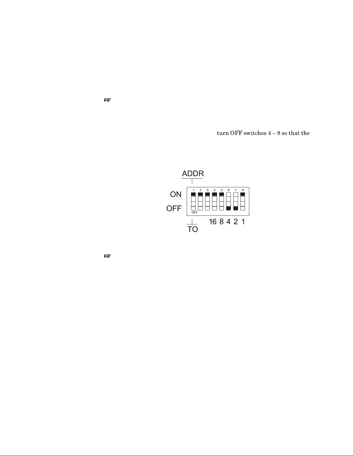
Set the interface to ADDR (Addressable) by positioning DIP switch 1 to ON.
This makes the 4421 respond
to controller commands.
Figure 12
IEEE Interface Default
DIP Switch Settings
Note:
lever). Examine the DIP switch to determine the ON and OFF positions.
Set the primary address using the DIP switches. The primary address is fac-
tory set to 6, but can be set to any va
the controller) To set the primary address,
sum of the bits turned off equals th
below, the address is set to 6 (the off switches have values of 4 and 2).
Note:
devices on the bus. When programming the controller, the address in the program must be the same as the addre
device on the bus must have a different primary address.
There are several button styles on DIP switches (slide, rocker,
lue between 1 and 31 (0 is reserved for
e desired primary address. In Figure 12
The primary address is used by the
ss set on the interface module. Each
controller to refer to specific
Talker-Only Mode
The Bird 4421 can be set up for manual operation while automatically sending
data to an output device (Talker-Only Mode). To do so, turn DIP switch 1 OFF
and cycle the power. TALK will be displayed.
In Talker-Only mode
When the measurement is complete, the
LISTEN turns on momentarily. A listen-only device on the bus, such as a
printer, can read the value. The power me
button press.
Command Syntax
The Bird 4421 accepts two types of
commands, such as Device Clear (DCL),
device. Device-depende
, pressing a button on the me
information is sent to the bus and
ter is then ready to accept another
commands. General bus commands are
that apply to any IEEE interfaced
nt commands are specific to the 4421.
ter triggers a measurement.
15
Page 28

Bird 4421 RF Power Meter
If an invalid command is se
serial poll byte and the offending command is not executed.
A group of device-dependent commands can be sent as a single string as long
as like command categories are not re
This string sets up the 4421 to send
Note:
Note:
As a command string is processed by th
stored in a separate location. Two co
stored in the same location, so that
first one.
General Bus Commands
The general bus commands supported by the IEEE-488 interface feature are
listed in Figure 13. The syntax for ex
controllers; check the documentation su
proper command structure.
Figure 13
IEEE-488
General Bus
Commands
Command Effect on Bird 4421
IDN?
REN
GTL
LLO
nt to the unit, an error co
no prefixes, read forward dBm, make one
Commands can be ente
Only the last command entered of
Gives product identification
Goes into remote mode when next addressed
Cancels remote mode, restores local operation
Locks out local operation
red in either uppe
e 4421, each category of command is
mmands of the same category will be
the second will overwrite and erase the
ecuting general commands varies among
pplied with your controller for the
ndition is placed in the
r or lower case.
each category will be executed.
ID
entificatio
N
Function
Remarks
IFC
DCL Returns to default conditions
SDC
GET
SPE, SPD
Goes into talker and listener-idle status
Returns to default conditions
Triggers reading in T2 and T3 modes
Puts the status byte on the bus
(IDN?)
Product identifies itself
Replies command same as U2
16
Page 29

IEEE-488 GPIB Interface
R
emote
EN
able (REN)
Function
Remarks
Enables remote operation.
The unit must be addressed to
The REMOTE indicator turns on wh
Go To Local (GTL)
Function
Remarks
L
ocalLOckout (LLO)
Function
Returns device to local operation.
Issuing a GTL command whil
clear the lockout condition.
The REMOTE indicator turns off.
The LISTEN indicator remains on.
Disables local operation of
listen after setting REN true.
en this command is received.
e the device is in Local Lockout mode does not
all devices on the bus.
I
nterFace
Remarks
Clear (IFC)
Function
Remarks
REN must be true to use LLO.
LLO is cleared by setting REN false.
Terminates all bus activity and passes
All devices are set to talker
LISTEN mode is cancelled, an
and listener idle states.
d its indicator is turned off.
control to the system controller.
17
Page 30

Bird 4421 RF Power Meter
D
eviceCLear (DCL)
Function
Remarks
Figure 14
IEEE-488 Default
Conditions
S
electiveDevice
Function
Resets the status of
Does not change the current interface mode.
The 4421 returns to the factory default condition listed in Figure 14.
Default Condition Related Command
Forward Carrier Wave
Auto Range ON
Two Terminators (CR LF)
Prefixes YES
Trigger One Shot on Talk Address
Send EOI with last byte of message
all devices to an initialized state.
FC
RYY
YT
PY
T1
M00
KY
Clear (SDC)
Resets the status of a selected device to an initialized state.
Remarks
G
roupExecute
Function
Remarks
Only the device addre
The 4421 returns to the fa
ssed will be cleared.
ctory default condition.
Trigger (GET)
Initiates a measurement for all
The 4421 must be already set to trigger on GET.
Used to synchronize measurements of multiple instruments.
devices set
to trigger on GET.
18
Page 31
IEEE-488 GPIB Interface
S
erialPollingEnable/
Disable (SPE/SPD)
Function
Remarks
Figure 15
IEEE Status
Byte Description
Enables or disables the
During remote operation, periodically
Failure to detect a service request
The SPE command puts all devices in
addressed. The SPD command clears the SRQ bit (bit 6) and ends the polling
sequence.
When addressed a device sends its status byte to the controller. A value of 1
for a bit means that the device condition th
means that the condition is false.
The 4421 does not use all bits of the stat
along with a description and how to reset them.
Bit Name Condition
6 SRQ Set if a service request is generated by the
serial polling sequence.
CAUTION
monitor the bus se
could result in equipment damage.
serial poll mode waiting to be
at bit refers to is true. A value of 0
us byte. Figure 15 lists the bits used,
4421. If an SRQ has been received by the
controller and this bit is cleared, other
instruments on the bus should be checked to
determine where the SRQ occurred.
rvice request line.
Clea red by a serial poll of the 4421.
3 Measurement
Complete
2 Reading
Underflow
1 Reading Overflow Set when the RF power is overrange and a
0 Error Set if an illegal device-dependent command
Set when the power meter has completed a
reading.
Clea red by requesting a reading over the bus.
Set when the RF power is underrange and a
reading has been completed.
Clea red by requesting a reading over the bus.
reading has been completed.
Clea red by requesting a reading over the bus.
(IDDC) or illegal device-dependent command
option (IDDCO) was received, or if the power
meter fails the self test.
Cleared by reading the U1 status word. The U1
on page 25.
19
Page 32

Bird 4421 RF Power Meter
Device Dependent Commands
The device-dependent commands used by the 4421 Power Meter are listed in
Figure 16, organized by category.
Figure 16
IEEE-488
Device Dependent
Command
Summary
Note:
The programming card also ha
s a complete command list.
Category Command Description
Measurement FC
FD
RC
RD
SW
RL
MN
MX
Range RYY
R00 to R17
RNN
Terminators YT
YO
YN
Prefixes PY
PN
Triggers T0
T1
T2
T3
T4
T5
Serial Polling M00
M01
M02
M04
M08
Status U0
U1
U2
Self-Test J0
EOI Response KY
KN
Writable Store WXXXXXX
Forward carrier wave
Forward dBm
Reflected carrier wave
Reflected dBm
Standing wave ratio
Return loss
Minimum value
Maximum value
Auto range on
Manual ranges
Auto range off, stay
Two terminators: CR, LF
One terminator: CR
No terminator
Prefix YES
Prefix NO
Continuous on TALK
One shot on TALK
Continuous on GET
One shot on GET
Continuous on measurement command
One shot on measurement command
Do not generate SRQ
Generate SRQ on error
Generate SRQ on me
Generate SRQ on measurement underrange
Generate SRQ on operation complete
Send back current machine state
Send back error conditions
Send back revision levels
Run self-test
Send EOI on last byte
Do not send EOI on last byte
Place XXXXXX in RAM
at present range
asurement overrange
20
Page 33

IEEE-488 GPIB Interface
F
orward
F
orward
R
eflected
R
eflected
Carrier Wave (FC)
dBm (FD)
Carrier Wave (RC)
dBm (RD)
S
tanding
R
eturn
Function
Remarks
Wave Ratio (SW)
Loss (RL)
Function
Remarks
Selects forward or reflected RF power measurement mode.
Measurement results are returned in Watts or dBm.
Selects SWR or return loss match measurement mode.
Measurement results are returned in VSWR or dB.
MiNimum Value (MN)
MaXimum Value (MX)
Function
Remarks
Selects minimum or maximum measurement mode.
Another measurement must be select
Returns the minimum (or maximum) valu
ed before selecting min or max.
e of the previous measurement type.
21
Page 34
Bird 4421 RF Power Meter
Range (Rxx)
Function
Remarks
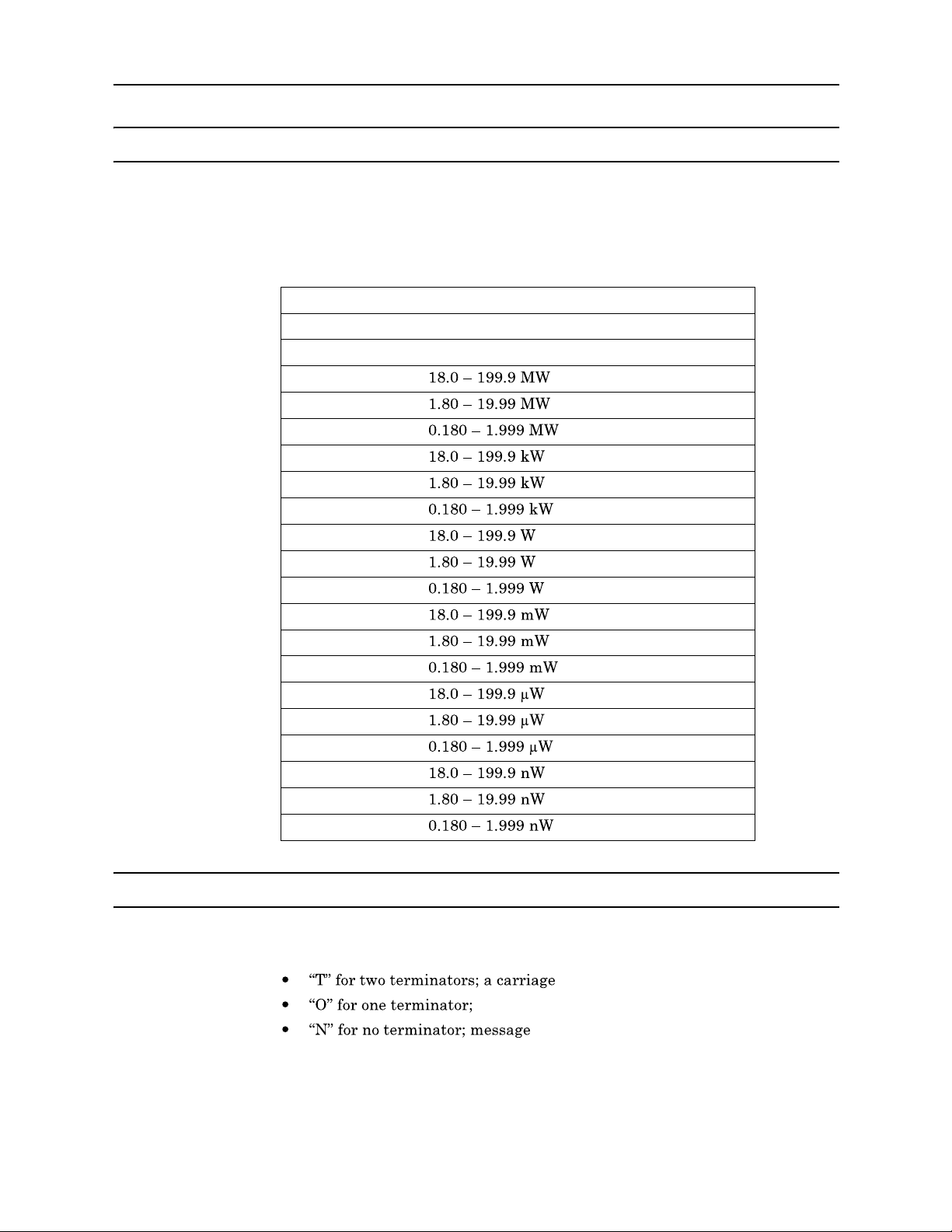
Figure 17
Measurement
Ranges
Selects a measurement rang
If the selected range is outside the ra
command is ignored.
Command Power Range
RYY
RNN
R17
R16
R15
R14
R13
R12
R11
R10
R09
R08
R07
R06
R05
R04
R03
R02
R01
R00
Turn auto range on
Turn auto range off. Keep present range
e listed in Figure 17.
nge of the connected power sensor, the
Terminators (Yx)
Function
Remarks
22
Selects the characters that follow
a carriage return(CR).
Many controllers use the terminator sequ
string. Using incorrect term
inators can lock the bus.
the end of a data string. Set x to:
return(CR) and a line feed(LF).
can be terminated by EOI.
ence to recognize the end of an input
Page 35
IEEE-488 GPIB Interface
Prefixes (Px)
Function
Remarks
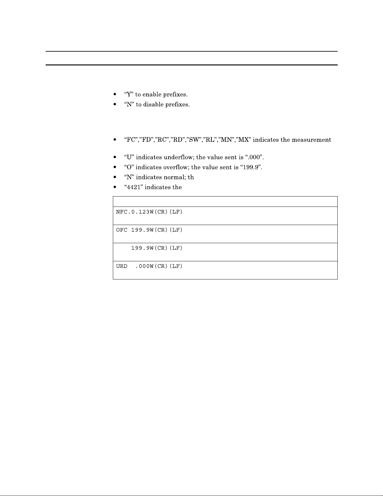
Figure 18
Prefix Examples
Turns the prefix mode on or off. Set x to:
Prefixes are sent over the bus with th
of the current measurement (see Figure 18 for examples):
type.
e value sent is a norm
Bird model number.
Data String Description
e measurement, and indicate the status
al on-scale reading.
Normal (N) forward carrier wave (FC),
prefixes on
Overflowed (O) forward carrier wave
(FC), prefixes on
Overflowed forward carrier wave,
prefixes off
Underflowed (U) reflected dBm (RD),
prefixes on
23
Page 36
Bird 4421 RF Power Meter
Triggers (Tx)
Function
Remarks
Figure 19
Trigger Conditions
Selects the condition which will trigger a reading (see Figure 19).
Failure to trigger device before requ
esting a reading will lock the bus.
T1 halts the bus until a reading is available.
T0 and T1 do not set the
T2, T3, T4, and T5 set a SRQ when
Fastest reading rate is 2.4 readings
Command Trigger Condition
T0
T1
T2
T3
T4
T5
measurement complete SRQ.
the measurement is complete.
/second; slowest is 1 reading/sec.
Continuous on ta lk
One shot on talk
Continuous on GET
One shot on GET
Continuous on measurement command
(FC,FD, RC, RD, SW, RL, MN, MX)
One shot on measurement command (FC,
FD, RC, RD, SW, RL, MN, MX)
SRQ
Mask (Mxx)
Function
Remarks
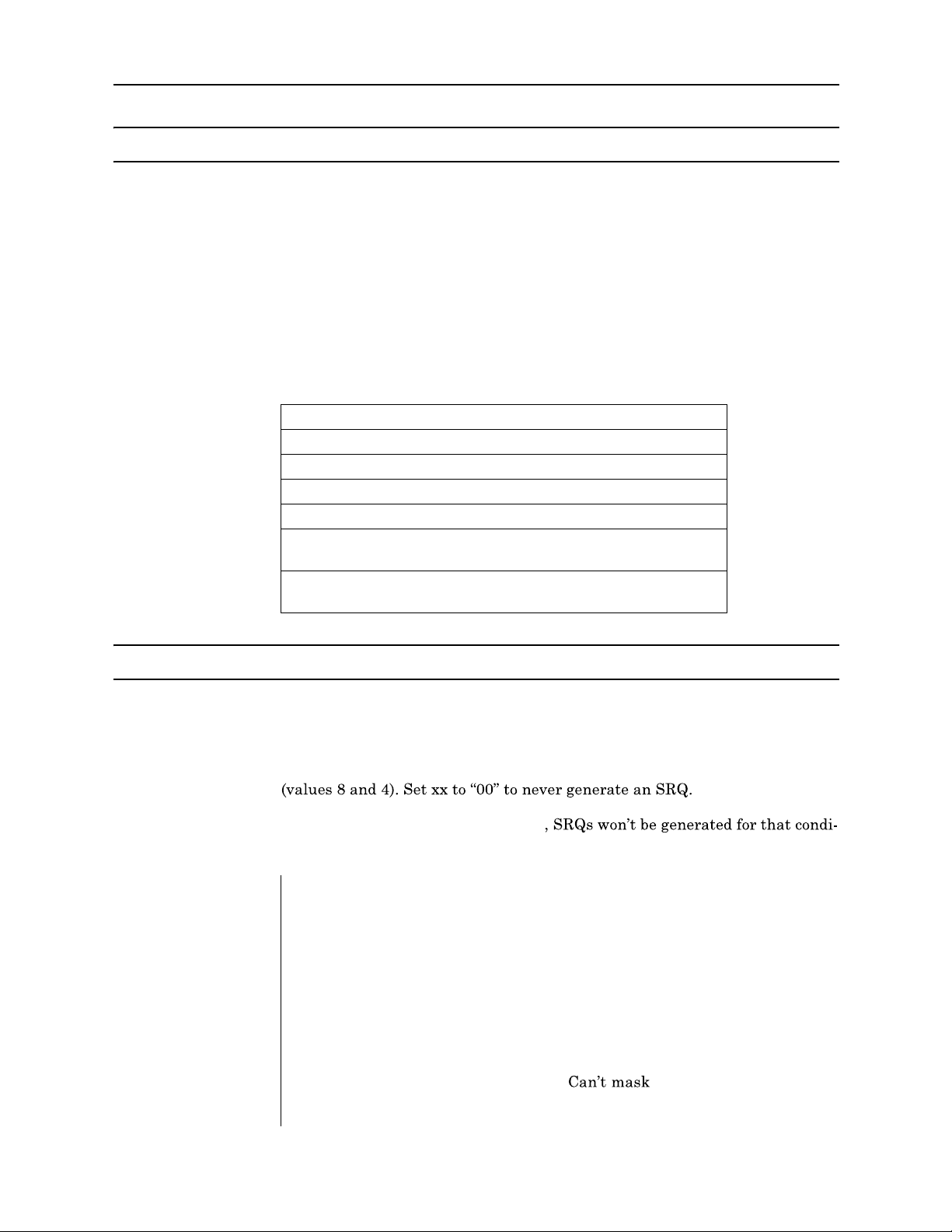
SRQ Mask Bits
Figure 20
Selectively masks status bits to
Set xx to the sum of the binary values
example, M12 would set the SRQ for bo
prevent unwanted service requests.
of the desired SRQ trigger bits. For
th operation complete and underrange
If a status bit is masked (bit set to 0)
tion.
Binary Value Bit Number Message
1 0 (LSB) Error (IDDC, IDDCO, self-test fail)
2 1 Measurement overrange
4 2 Measurement underrange
8 3 Operation complete
4 Not Used
5 Not Used
6
7 (MSB)
Not Used
24
Page 37
IEEE-488 GPIB Interface
Status (Ux)
Function
Remarks
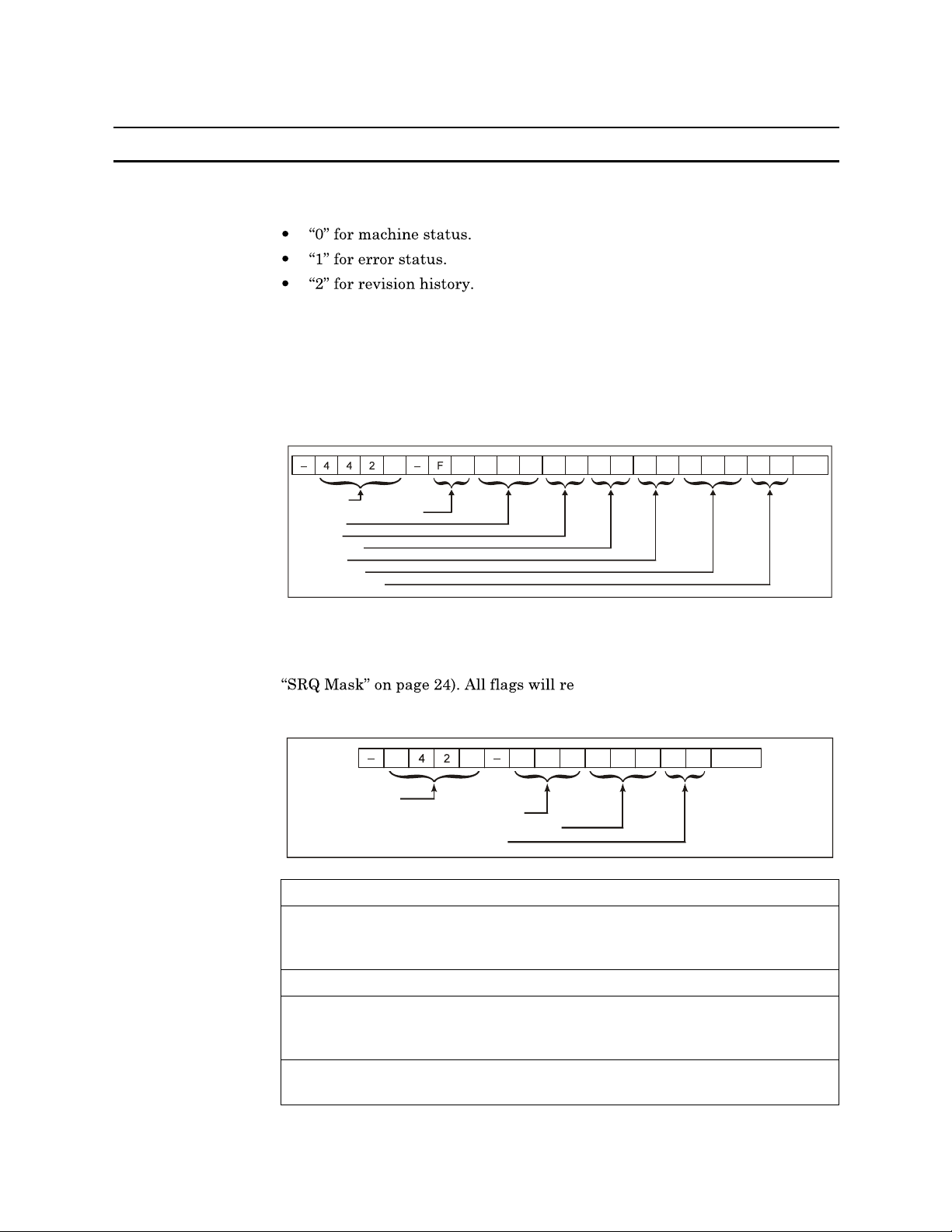
Figure 21
Machine Status
Word Format
Reads a status word and returns the information as a string. Set x to:
After sending the status command, a stat
unit is addressed to talk. To ensure th
tus word should be requested as soon
Machine Status Word (U0):
The format of the mach
us word is sent the next time the
e correct status is transmitted, the sta-
as possible after the command is sent.
ine status word is
shown in Figure 21. The default values are also shown.
0 C
Header
Measurement Function
Range
Prefix
Terminator
Trigger
SRQ Mask
EOI Response
Error Status Word (U1):
ble error messages are shown
R Y Y P Y Y T T 1 M
The format of the error status word and the possi-
in Figure 22. When an e
0 0
rror occurs, an error is
also flagged in the status (serial poll) byte, and a SRQ may be generated (See
vert to their non-error states after
the U1 command is sent.
K Y
TERM
Figure 22
Error Status
Word Format
4
Header
Command Status (shown valid)
Command Option Status (shown valid)
Self-test results (shown fail)
0
C
V
M V
C 0
F L
TERM
Status Meaning Description
ICM Invalid Command Set when an illegal device-dependent
command (IDDC) such as V2 is
received. (V is illegal)
VCM Valid Command Set when no IDDC is received.
ICO Invalid Command
Option
Set when an illegal device-dependent
command option (IDDCO) such as T6 is
received. (6 is illegal)
VCO Valid Command
Set when no IDDCO is received.
Option
25
Page 38
Bird 4421 RF Power Meter
PS Self-Test Pass Set when a self-test has been initiated
by the J 0 command and the test result
is acceptable.
FL Self-Test Fail Set when the self-test has failed. (This
is the default condition.)
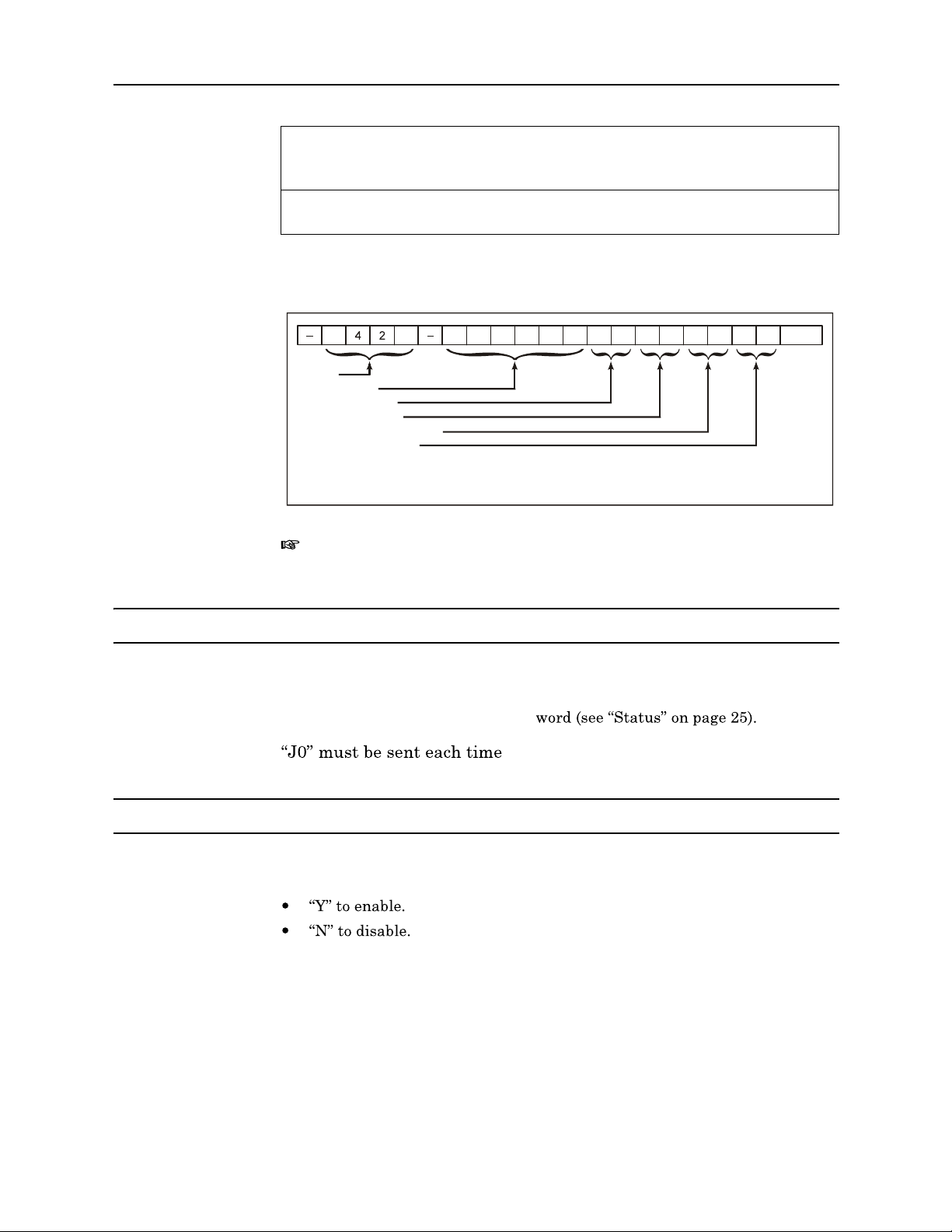
Figure 23
Revision History
Word Format
Self Test (J0)
Function
Revision History Word (U2):
The format of the revi
shown in Figure 23.
4
Header
Writable stores
Software Rev level
Hardware Rev level
IEEE-488 1978 compliance
IEEE-488 Bus address
* YY is replaced with current software revision level.
** ZZ is replaced with current hardware revision level.
Note:
0
X X X X X X Y Y Z Z 7
If Writable stores parameter ha
responds only with -4420-.
Initiates a hardware and software test.
sion history word is
* **
8 0 6
s not been set, this command
TERM
Remarks
End Or Identify (Kx)
Function
Remarks
26
Results are stored in the U1 status
before reading the result.
Enables or disables the End or
Disabling EOI can cause some controllers
used.
When enabled, EOI is only asserted at
Identify (EOI) signal. Set x to:
to lock unless another terminator is
the end of a multiple byte string.
Page 39

IEEE-488 GPIB Interface
Writable Store (Wxxxxxx)
Function
Remarks
Storage for six bytes of ASCII data.
Data stored is lost when the 4421 is turned off.
Data is sent back as part of the U2 status word.
27
Page 40

Bird 4421 RF Power Meter
28
Page 41

Description
Cable Connector
Chapter 5
This chapter discusses setup of the RS-232 interface feature and describes the
RS-232 commands that apply to the Bird 4421. Operators should understand
EIA Standard RS-232-C and have basic computer programming skills before
writing any programs.
The Bird 4421 RS-232 interface feature is an integral part of the I/O hub circuit board inside of the mm21. An eigh
operational conditions such as baud rate, parity, and stop bits. The bottom
line of the display indica
The interface uses a standard 25-pin RS-232 connector. Pin assignments are
listed in Figure 24. If the controller us
not attempt to rewire th
should be used for rewiring instead.
tes the current bus status.
t-position DIP switch
es a different wiring arrangement, do
RS-232 Interface
is used to set
Figure 24
RS-232 Pin
Assignments
Indicators
Pin Designation Notes
1 Protection Ground Chassis Ground
2 Transmit Data
3 Receive Data
4 Request to Send (Output) Set true after module power up
5 Clear to Send (Input) Set by input device. When true, it
enables the module to transmit. When
false, it disables transmission.
6 Data Set Ready (Input) Set internally true by module
7 Signal Ground Return path for data and control signals
8 Receive Signal DET (Input) Set true by module
20
Data Terminal Ready (Output) Set true after module power up
status of the Bird 4421 when used
TALK:
is always shown when the unit
When TALK is displayed, the power
splay shows indicato
with the RS-232 interface. These are:
meter is transmitting data. This
rs describing the
LISTEN:
When LISTEN is displayed, the power meter is receiving data.
29
Page 42
Bird 4421 RF Power Meter
Setup
DIP Switch
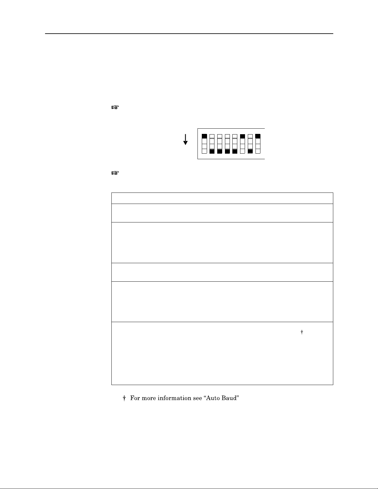
Figure 25
RS-232 Interface
Default DIP Switch
Settings
Set the DIP switches according to appl
the controller. Available settings and fact
Note:
lever). Examine the DIP switch to determine the ON and OFF positions.
There are several button styles on DIP switches (slide, rocker,
ication needs and the requirements of
ory defaults are listed in Figure 25.
21 43 65 87
ON
Note:
tings will not become effective unitl
Switch Function Description
1 Stop Bit ON 1 Stop Bit
2
If you change switch settings
OFF 2 Stop Bits
Command
Mode
ON ENT command needed before sending
reading to controller*
OFF Trigger automatically sends reading
Reading also sent when front panel push button
pressed
when the unit is ON, the new set-
you turn power OFF and then back ON.
*
3 Word Length ON 8 Data Bits*
OFF 7 Data Bits
4,5
6,7,8
* Default factory setting
Parity (4) (5)
ON ON
ON OFF
OFF ON
OFF OFF
Baud Rate (6) (7) (8)
ON ON
ON OFF ON
ON OFF OF F
OFF ON ON
OFF ON OFF
OFF OFF ON
OFF OFF OFF
ON
No Parity*
Odd Parity
Even Parity
Mark Parity
Auto Baud
300
600
1200
2400*
4800
9600
30
Page 43

RS-232 Interface
Auto Baud
Auto Baud is used to automatically de
After setting DIP switches 1 through 5,
baud:
1. Set DIP switches 6, 7, and 8 to ON.
2. Connect a controller to the power meter.
3. Turn the power meter on.
4. Send the character U (hexadecimal 55
5. Wait 1 second.
If, after 30 seconds, the
will choose a rate based on da
such as parity and stop bits must be manually selected.
Talker-Only Mode
The Bird 4421 can be set up for manual operation while automatically sending
data to an output device (Talker-Only Mode). To do so, turn DIP switch 2 OFF
and cycle the power. TALK will be displayed.
meter.
determined. If not, repeat steps 4 and 5.
module cannot absolutely determine a baud rate, it
ta acquired during the test.
Note:
Auto Baud is the only automatica
termine the correct
follow the steps below to use auto
) from the controller to the power
lays LISTEN, the baud rate has been
lly chosen setting. Other items
transmission rate.
In Talker-Only mode
When the measurement is complete, th
Command Syntax
The Bird 4421 accepts two types of
commands, such as Initialize (INT),
device. Device-depende
If an invalid command is se
serial poll byte and the offe
A group of device-dependent commands can be sent as a single string as long
as like command categories are not re
This string sets up the 4421 to send
As a command string is processed by th
stored in a separate location. Two co
stored in the same location, so that
first one.
Note:
Note:
, pressing a button on the me
e information is sent to the bus.
commands. General bus commands are
that apply to any RS-232 interfaced
nt commands are specific to the 4421.
nt to the unit, an error co
nding command is not executed.
no prefixes, read forward dBm, make one
Commands can be ente
Only the last command entered of
red in either uppe
e 4421, each category of command is
mmands of the same category will be
the second will overwrite and erase the
ter triggers a measurement.
ndition is placed in the
r or lower case.
each category will be executed.
31
Page 44

Bird 4421 RF Power Meter
General Bus Commands
Figure 26
RS-232
General Bus
Commands
IN
iTialize (INT)
Function
Remarks
ENT
er (ENT)
The general bus commands
listed in Figure 26.
Command Effect on Bird 4421
INT
ENT
TRG
B1 to B7
XO/XF
Resets the Bird 4421 and return
If INT is linked with
from that command by a space.
any other command within a st
supported by the RS-232 interface module are
Returns to default conditions
Sends a reading to the controller
Triggers reading in T3 mode
Selects a baud rate
Enables/disables software handshake
s it to the factory defaults.
ring, it must be separated
Function
Remarks
TR
iGger (TRG)
Function
Makes the power meter transmit
A measurement must have already been triggered, placing a reading in the
output buffer.
To send a reading whenever a measurement is triggered, set DIP switch 2 to
OFF. The ENT command will not need to be sent.
Initiates a measurement if the powe
a reading to the controller.
r meter is in trigger mode (T3).
32
Page 45

RS-232 Interface
Baud Select (Bx)
Function
Remarks
Figure 27
Baud Rates
Selects a baud rate
When the meter recognizes a valid Bx
changed. (The contro
wise sending commands wo
This command overrides
Command Baud Rate
B2 300
B3 600
B4 1200
B5 2400
B6 4800
B7 9600
Xmission Flow Control (XO/XF)
Function
Enables or disables th
listed in Figure 27.
command, its baud ra
ller is assumed to
uld not be possible.)
the DIP switch setting.
e XON/XOFF flow control.
be transmitting at
te is immediately
the new rate; other-
Remarks
XO enables flow control.
XF disables flow control.
When data is being sent from the powe
trol is enabled, data transmission will be suspended when the XOFF character
(hexadecimal 13) is sent by the comp
XON (hex 11) is sent by the computer.
When data is being sent from the comput
sent to the computer when the input buff
computer when the buffer has emptied.
r meter to the computer and flow con-
uter. Transmission will resume when
er to the power meter, XOFF will be
er fills up. XON will be sent to the
33
Page 46

Bird 4421 RF Power Meter
Device Dependent Commands
The device-dependent commands used by the 4421 Power Meter are listed in
Figure 28, organized by category.
Figure 28
RS-232 Device
Dependent
Command
Summary
Category Command Description
Measurement FC Forward carrier wave
FD
RC
RD
SW
RL
MN
MX
Forward dBm
Reflected carrier wave
Reflected dBm
Standing wave ratio
Return loss
Minimum value
Maximum value
Range RYY Auto range on
R00 to R17
RNN
Manual r anges
Auto range off, stay at present
range
Terminators YT Two terminat ors: CR, LF
YO
YN
One terminator: CR
No terminator
Prefixes PY Prefix YES
PN
Prefix NO
Triggers T0 Continuous on ENT
T1
T3
T5
One shot on ENT
One shot on TRG
One shot on measurement command
Status U0 Send back current machine state
U1
U2
Send back error conditions
Send back revision levels
Self-Test J0 Run self-test
Writable Store WXXXXXX Place XXXXXX in RAM
34
Page 47

RS-232 Interface
F
orward
F
orward
R
eflected
R
eflected
Carrier Wave (FC)
dBm (FD)
Carrier Wave (RC)
dBm (RD)
S
tanding
R
eturn
Function
Remarks
Wave Ratio (SW)
Loss (RL)
Function
Remarks
Selects forward or reflected RF power measurement mode.
Measurement results are returned in Watts or dBm.
Selects SWR or return loss match measurement mode.
Measurement results are returned in VSWR or dB.
MiNimum Value (MN)
MaXimum Value (MX)
Function
Remarks
Selects minimum or maximum measurement mode.
Another measurement must be select
Returns the minimum (or maximum) valu
ed before selecting min or max.
e of the previous measurement type.
35
Page 48
Bird 4421 RF Power Meter
Range (Rxx)
Function
Remarks
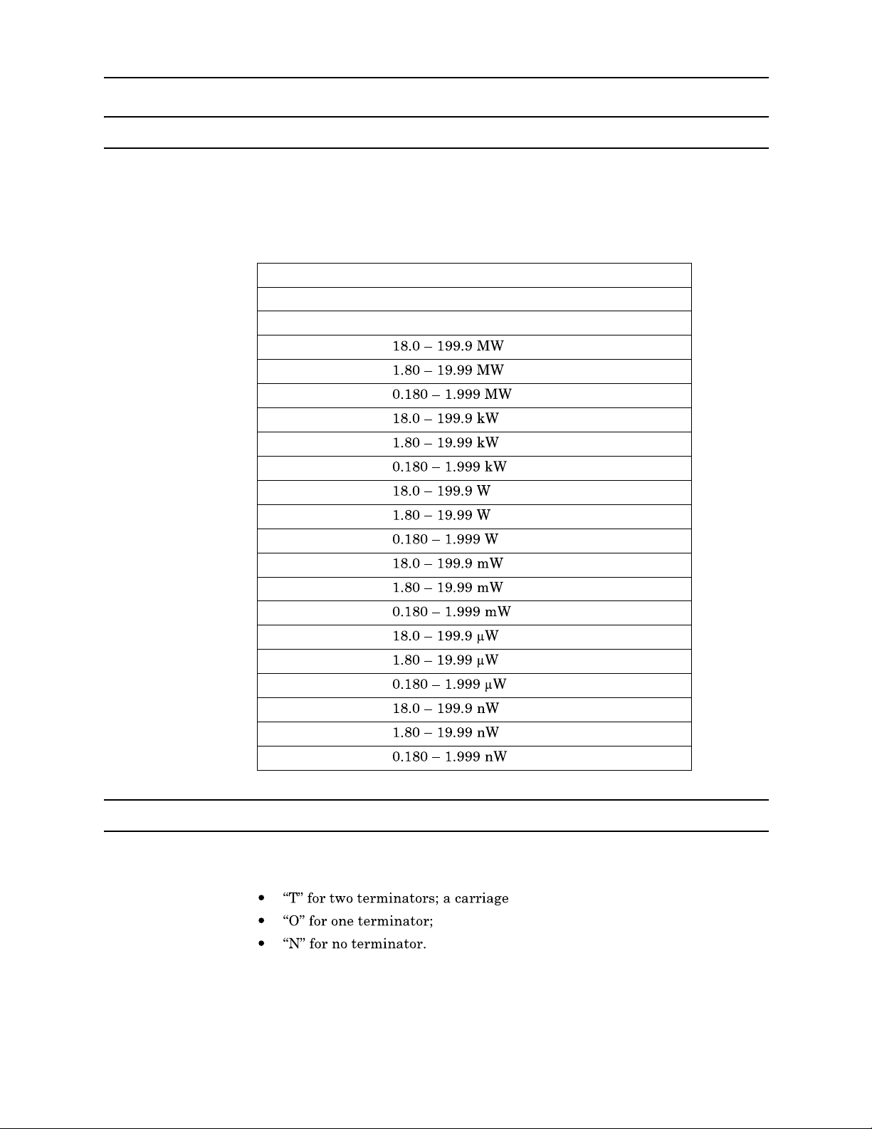
Figure 29
Measurement
Ranges
Selects a measurement rang
If the selected range is outside the ra
command is ignored.
Command Power Range
RYY
RNN
R17
R16
R15
R14
R13
R12
R11
R10
R09
R08
R07
R06
R05
R04
R03
R02
R01
R00
Turn auto range on
Turn auto range off. Keep present range
e listed in Figure 29.
nge of the connected power sensor, the
Terminators (Yx)
Function
Remarks
36
Selects the characters that follow
a carriage return(CR).
Many controllers use the terminator sequ
string. Using incorrect term
inators can lock the bus.
the end of a data string. Set x to:
return(CR) and a line feed(LF).
ence to recognize the end of an input
Page 49
RS-232 Interface
Prefixes (Px)
Function
Remarks
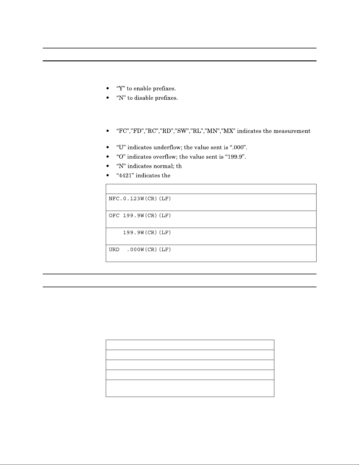
Figure 30
Prefix Examples
Turns the prefix mode on or off. Set x to:
Prefixes are sent over the bus with th
of the current measurement (see Figure 30 for examples):
type.
e value sent is a norm
Bird model number.
Data String Description
e measurement, and indicate the status
al on-scale reading.
Normal (N) forward carrier wave (FC),
prefixes on
Overflowed (O) forward carrier wave
(FC), prefixes on
Overflowed forward carrier wave,
prefixes off
Underflowed (U) reflected dBm (RD),
prefixes on
Triggers (Tx)
Function
Remarks
Figure 31
Trigger Conditions
Selects the condition which will trigger a reading (see Figure 31).
Failure to trigger device before requ
Fastest reading rate is 2.4 readings
Command Trigger Condition
T0
T1
T3
T5
Continuous on ENT
One shot on ENT
One shot on TRG
One shot on measurement command
(FC, FD, RC, RD, SW, RL, MN, MX)
esting a reading will lock the bus.
/second; slowest is 1 reading/sec.
37
Page 50
Bird 4421 RF Power Meter
Status (Ux)
Function
Remarks
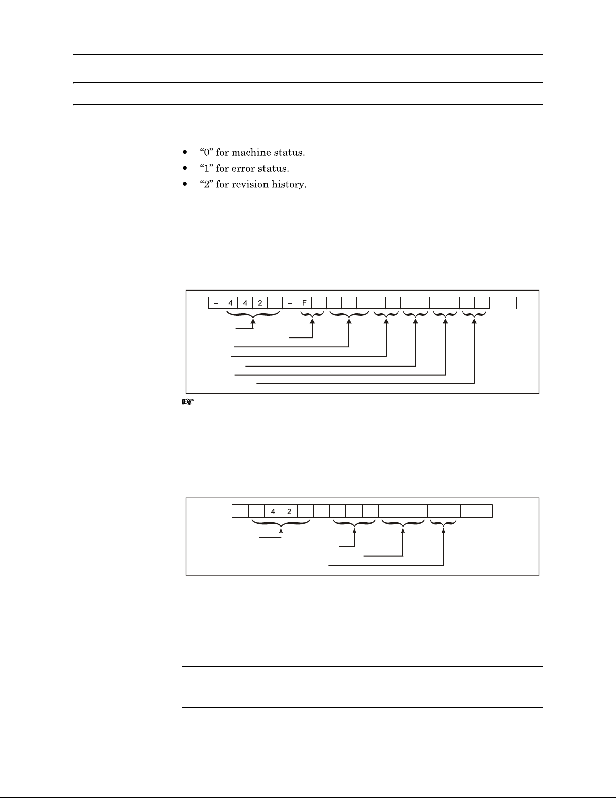
Figure 32
Machine Status
Word Format
Reads a status word and returns the information as a string. Set x to:
After sending the status command, a stat
unit is addressed to talk. To ensure th
tus word should be requested as soon
Machine Status Word (U0):
The format of the mach
us word is sent the next time the
e correct status is transmitted, the sta-
as possible after the command is sent.
ine status word is
shown in Figure 32. The default values are also shown.
0 C
Header
Measurement Function
Range
Prefix
Terminator
Trigger
XON / XOFF
Note:
This command sets the unit to the
remotely (through RS-232 or GPIB). Ther
R Y Y P Y Y T T 1 X
settings that were last issued
efore, it will over ride any manual
changes selected at the front panel of the unit.
0
TERM
Figure 33
Error Status
Word Format
Error Status Word (U1):
ble error messages are shown
The format of the error status word and the possi-
in Figure 33. All flags will revert to their non-
error states after the U1 command is sent.
4
Header
Command Status (shown valid)
Command Option Status (shown valid)
Self-test results (shown fail)
0
C
V
M V
C 0
F L
TERM
Status Meaning Description
ICM Invalid Command Set when an illegal device-dependent
command (IDDC) such as V2 is
received. (V is illegal)
VCM Valid Command Set when no IDDC is received.
ICO Invalid Command
Option
Set when an illegal device-dependent
command option (IDDCO) such as T6 is
received. (6 is illegal)
38
Page 51
RS-232 Interface
Figure 34
Revision History
Word Format
VCO Valid Command
Set when no IDDCO is received.
Option
PS Self-test Pass Set when a self-test has been initiated
by the J 0 command and the test result
is acceptable.
FL Self-test Fail Set when the self-test has failed. (This
is the default condition.)
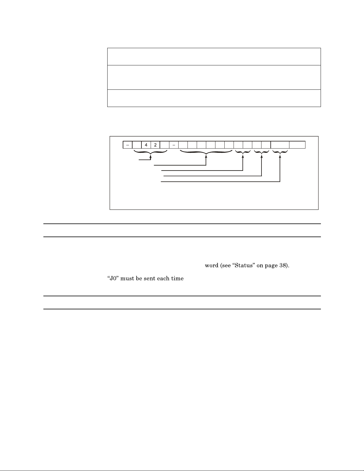
Revision History Word (U2):
The format of the revi
sion history word is
shown in Figure 34.
4
Header
Writable stores
Software Rev level
Hardware Rev level
Interface standard
* YY is replaced with current software revision level.
** ZZ is replaced with current hardware revision level.
0
X X X X X X Y Y Z Z
* **
RS-232
TERM
Self Test (J0)
Function
Remarks
Initiates a hardware and software test.
Results are stored in the U1 status
Writable Store (Wxxxxxx)
Function
Remarks
Storage for six bytes of ASCII data.
Data stored is lost when the 4421 is turned off.
Data is sent back as part of the U2 status word.
before reading the result.
39
Page 52

Bird 4421 RF Power Meter
40
Page 53
Chapter 6
This chapter describes routine maintenance, along with troubleshooting
instructions for the power meter and po
for the Bird Cal Cart are al
the unit to a qualified service center.
To avoid personal injury, disconnect th
performing any maintenanc
Never attempt to connect or disc
transmission line while RF power is being applied.
Leaking RF energy is a potential health hazard.
The Bird 4421 contains no user-serviceable parts.
so provided. For service beyond this level, return
e, including fuse replac
line voltage setting.
Do not remove its cover.
wer sensor. Disassembly instructions
WARNING
e power cord from the ac line before
WARNING
onnect RF equipment from the
WARNING
Maintenance
ement or changing the
Cleaning
Troubleshooting
The Bird 4421 Power Meter requires only simple, routine maintenance.
Wipe off dust and dirt regularly.
Check the connectors and cables for damage.
Clean the connector contacts with
Do not use harsh or abrasive
Clean the Bird 4421 Power Meter and its
with mild detergent and wa
that leaves no residue.
Since the power meter and po
is to determine which is malfunctioni
meter and perform the functi
functioning, refer to the troubleshootin
malfunctioning, retu
rn it for service.
ter only. Clean sensors with
wer sensor can only work together, the first step
onal test on page 43. If the power meter is mal-
alcohol or dry cleaning solvent.
CAUTION
detergents for cleaning.
display with a soft
a dry cleaning solvent
ng. Connect the power sensor to the
g table below. If the power sensor is
cloth dampened
41
Page 54
Bird 4421 RF Power Meter
Due to the complexity of
general maintenance should not be attempted.
Removal or disturbance of
CAUTION
the Bird Power Sensor, field repairs beyond
the power sensor
of lifetime warranty.
cover can result in cancellation
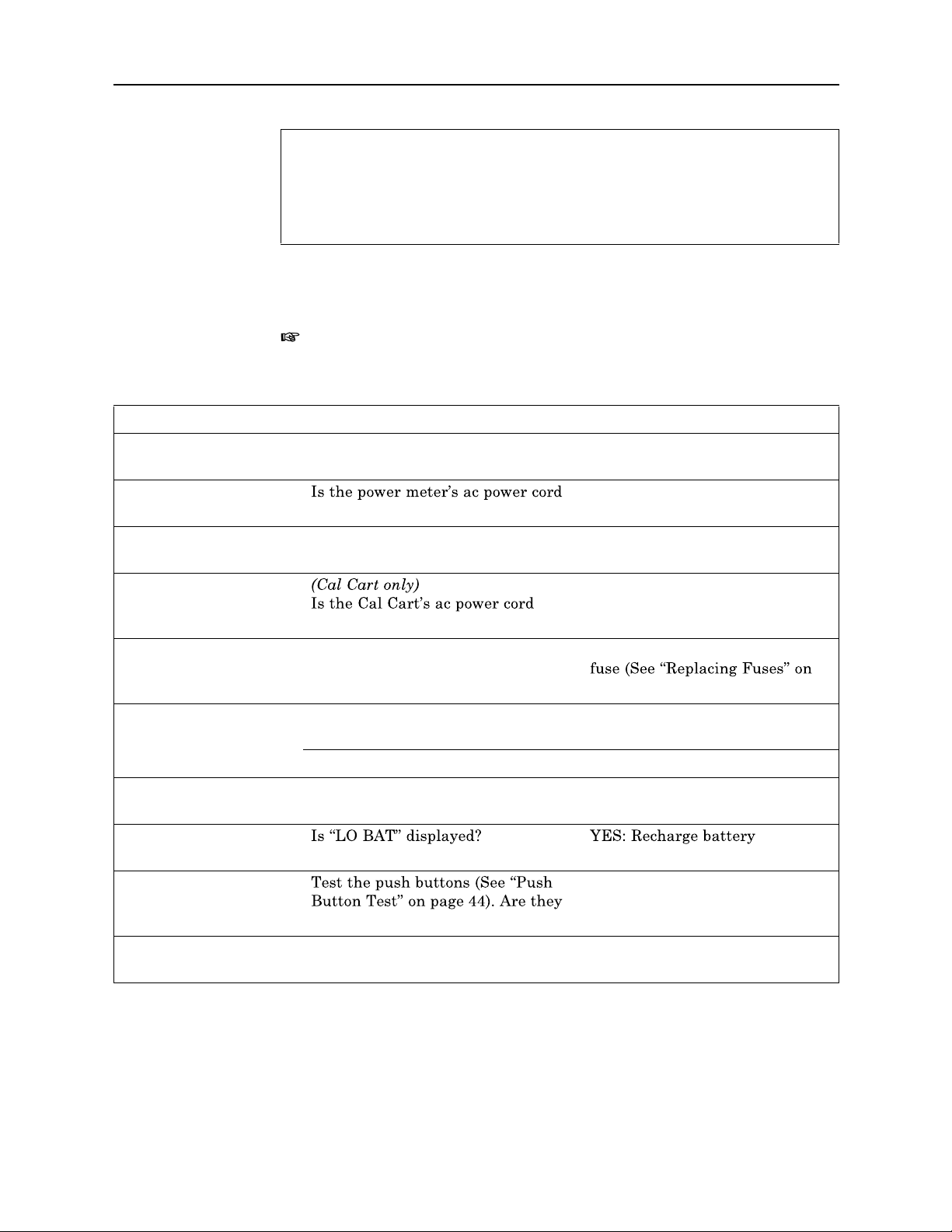
PROBLEM POSSIBLE CAUSE CORRECTION
Power meter has no
power
This manual cannot list all
If a malfunction is not listed or is not
contact a qualified service center.
Note:
check the sensor not covered by the safety
the safety cover over, then proceed as normal.
Have the batteries been charged? Recharge the batteries
connected?
Is the ON/OFF rocker switch on the
rear panel set to OFF?
connected to the ac line?
Blown fuse? Check fuse rating and replace
For power sensors in Cal Carts, following the test procedure will
malfunctions that may occur, or corrective actions.
corrected by the listed
cover. To test th
Connect the power cord
Set the switch to ON
Connect ac power
page 46)
corrective actions,
e other sensor slide
Dash moves across the
display
Display blank or not
updating
Power meter turns off
while on battery power NO: Return meter for service
Push buttons do not
respond
Every segment on the
display is lit
Is the sensor cable connected to both
the power meter and power sensor?
Is the sensor cable defective? Replace sensor cable
Have the batteries been charged? NO: Recharge battery
defective?
Connect sensor cable
YES: Return meter for service
Return meter for service.
Return meter for service
42
Page 55
Maintenance
IEEE-488 Interface
does not respond to the
interface link
RS-232 Interface does
not respond to the
interface link. Fails J 0
self-test command.
With the RS-232, the
power meter displays
operate as expected.
Functional Test
Are the address in the interface
program and the address setting on
Change the program or DIP
switch setting so that the
the DIP switches on the interface
module the same?
Replace I/O hub PCB
then check the status. Does the
power meter fail the self test?
Is the IEEE cable defective? Replace IEEE interface cable
Are the DIP switches set correctly? Set DIP switches
Is the RS-232 cable defective? Replace RS-232 interface cable
Is DIP switch 2 set correctly? For
Is DIP switch 1 set correctly? Set DIP switch 1 as indicated in
Figure 25
This test determines whether the powe
r meter or the sensor is malfunction-
ing.
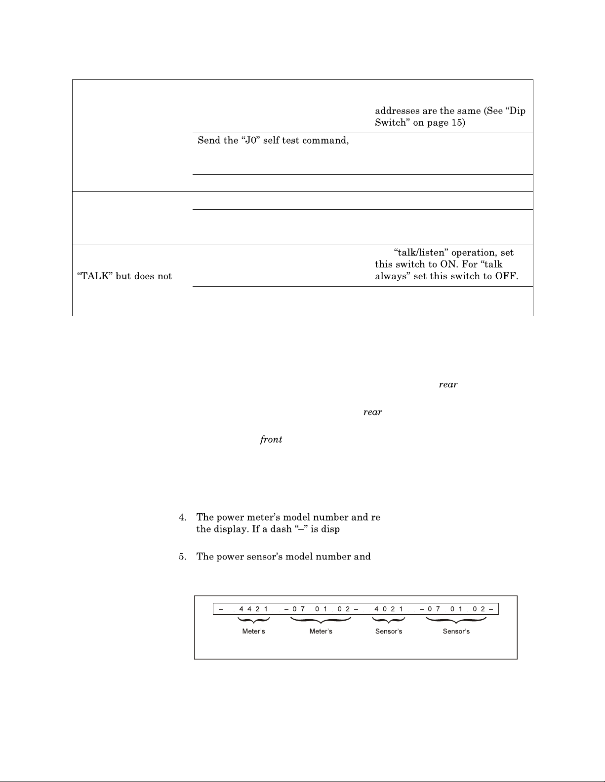
Figure 35
Test Display,
No Malfunction
1. Turn the power meter off.
The ON/OFF switch on the
OFF and the ac power cable should be connected.
2. Turn ON the ON/O
3. While holding down the FWD and
button on the
FF switch on the
SWR push buttons, press the ON/OFF
panel of the power mete
panel of the meter.
r. Immediately release all
three.
The unit tests the display on power up cycling through and activating each segment two times and th
en activating all segments at
once two times.
vision date shou
malfunctioning.
the display. If a dash
is displayed after the po
power sensor is malfunctioning.
Model
Number
Software
Rev. Date
layed instead, th
revision date should scroll across
Model
Number
en the meter is
wer meter data, then the
Software
Rev. Date
panel should be
ld scroll across
43
Page 56
Bird 4421 RF Power Meter
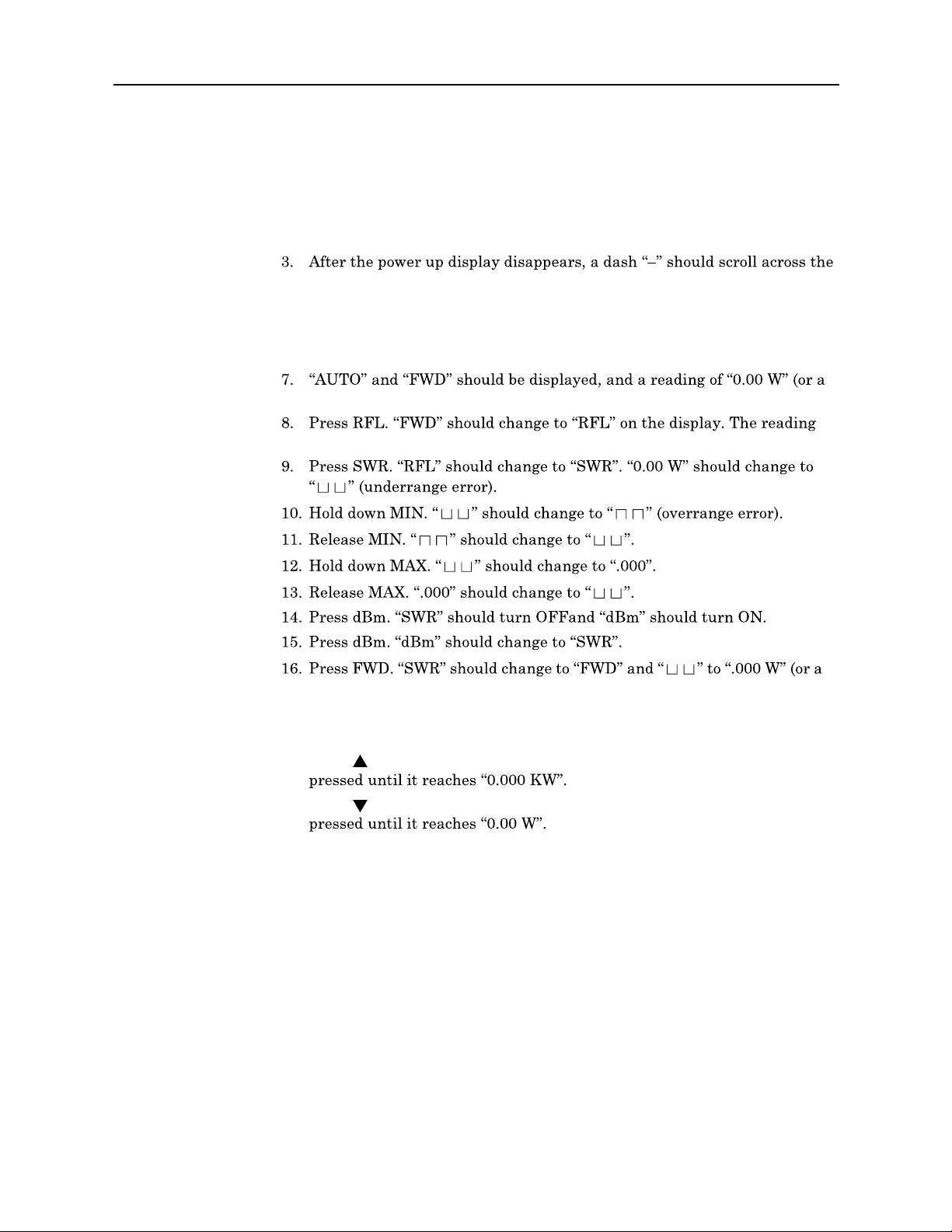
Push Button Test
This test checks that the push buttons and display are functioning properly. If
a push button is malfunction
1. Disconnect the power sensor.
2. Turn the power meter ON.
display.
4. Turn the power meter OFF.
5. Connect the power senson.
6. Turn the power meter ON.
very low number).
should remain the same.
ing, return the power meter.
very low number).
17. Press LIGHT. The back-
18. Press LIGHT. The back-
19. Press
20. Press
21. Turn the power meter OFF.
(up). The power meter should ch
(down). The power meter should ch
light should turn on.
light should turn off.
ange ranges each time it is
ange ranges each time it is
44
Page 57
Maintenance
O
CO
Repair
To avoid personal injury, disconnect th
performing any maintenanc
Front Panel (Cal Cart only)
WARNING
e power cord from the ac line before
e, including fuse replac
line voltage setting.
ement or changing the
If the power meter is mount
ac connections, it will be necessary to
1. Remove both screws on the fron
and the handle.
2. Pull on the handle set into the ba
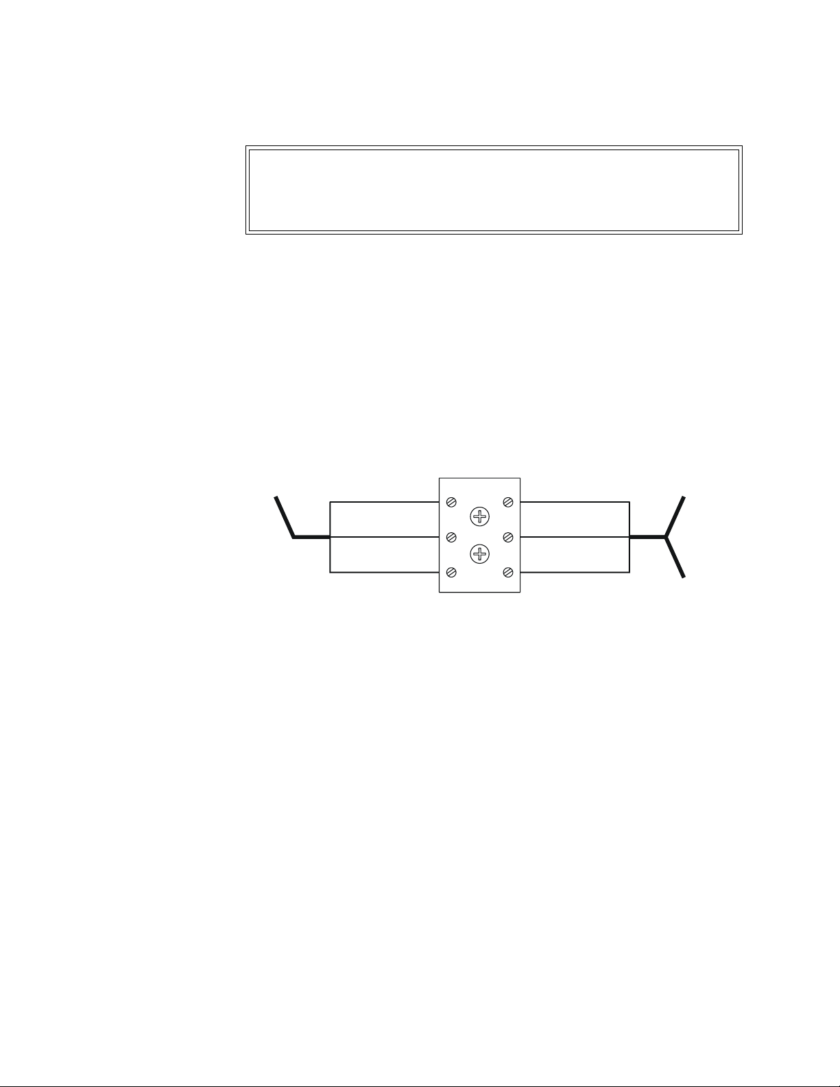
When making ac connections, refer to the following wiring diagram.
Figure 36
Cal Cart Wiring
Schematic
T
RD
REEL
Cord Reel (Cal Cart only)
To replace the cord reel:
ed in a Cal Cart, to access the power sensor or the
GRN/YEL (GND)
BLUE (NEUT)
BROWN (LINE)
remove the front panel of the Cal Cart.
t panel, between the RF connector
se of the front panel to remove it.
TO POWER
GRN/YEL (GND)
BLUE (NEUT)
BROWN (LINE)
METER
TO LOAD BLOWE
(
10 kW ONLY
R
)
1. Disconnect the cord reel from the terminal strip.
2. Unscrew the ac connector.
3. Unscrew and remove the cord reel.
4. Screw the replacement cord reel into place.
5. Thread the ac connector through th
the other end to the term
inal strip (See Figure 36).
e grommet, and connect the wires on
45
Page 58
Bird 4421 RF Power Meter
A
Replacing Fuses
WARNING
To avoid personal injury, disconnect th
performing any maintenance,
e power cord from the ac line before
including fuse replacement.
CAUTION
Failure to install the properly rated fuse may result in equipment damage
or nuisance failures.
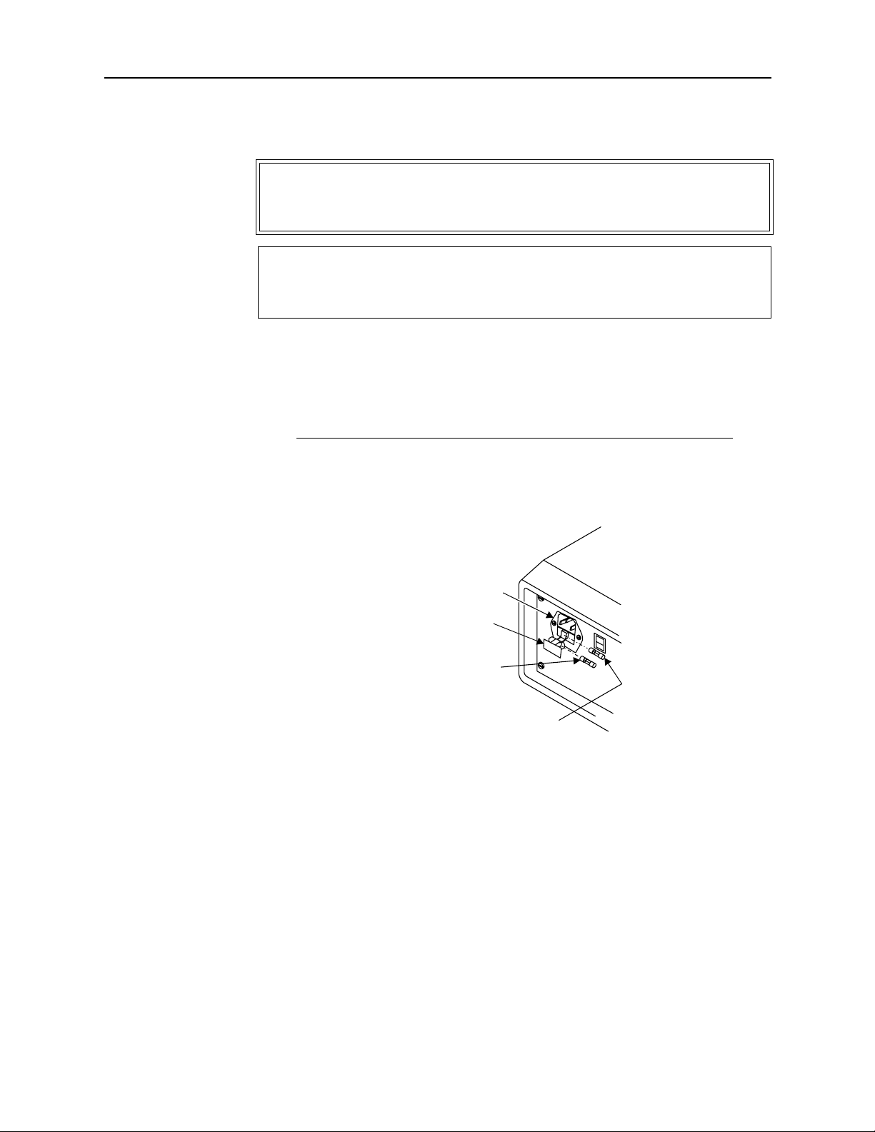
1. Gently pry the fuse drawer out of th
e ac module. The fuse holder does not
detach from the ac module.
2. Install the replacement fuses then clos
is a spare fuse and fuse 2 is the active fuse.
AC Line Voltage Fuse Rating
115 Vac T630 mA, 5x20 mm Time Lag Fuse
230 Vac T315 mA, 5x20 mm Time Lag Fuse
Figure 37
AC Line Fuse
C Module
Fuse
Drawer
Fuse 1
Fuse 2
e and secure the fuse holder. Fuse 1
46
Page 59
Maintenance
Replacing Batteries
WARNING
Exposed ac line voltage (115 VAC
power cord from the ac line before
or 230 VAC). Disconnect the
replacing the batteries. Failure
to comply may result in severe electrical shock or death.
1. Disconnect the ac power cord
2. Remove the four screws
3. Lift the top cover to access the
from the ac mains supply.
that secure the top cover.
attached ground wire then discon-
nect the ground wire and remove the cover.
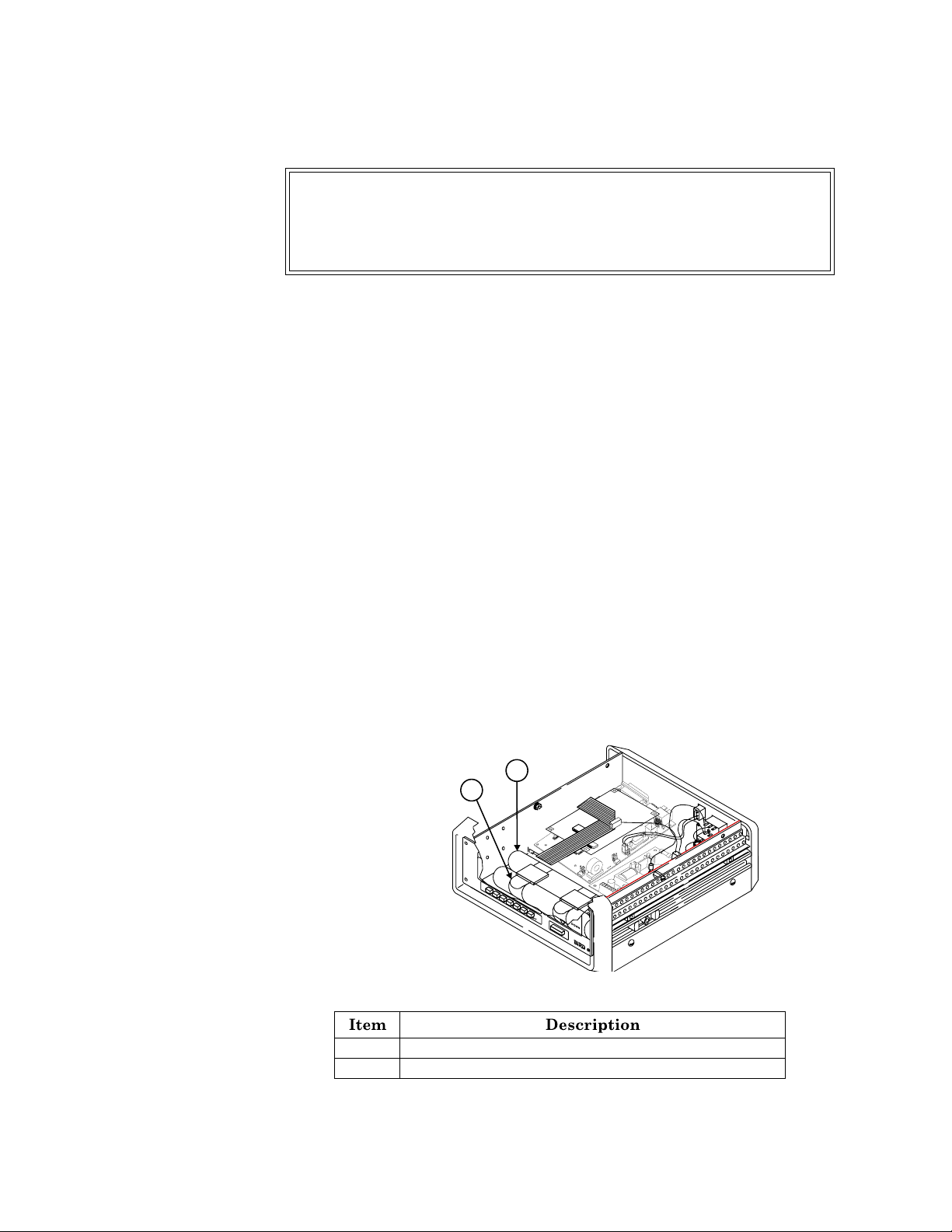
4. Unfasten the battery retaining be
(Figure 38). Be sure to note the
tery tubes before removing them.
5. Remove the batteries from each
teries. Be sure to note
the polarity (positive and negative) arrange-
ment of the batteries.
6. Install the battery tubes into the
belts. Be sure to position the re
taining belts as they were before
removal and tighten them securely.
7. Connect the ground wi
re to the top cover.
8. Install the top cover and secure
earlier.
Figure 38
Batteries
1
2
lts then remove the battery tubes
polarity and orientation of the bat-
tube and insert replacement bat-
unit and secure with the retaining
it with the four screws removed
1 Battery retaining belt
2 Battery tube (batteries inside)
47
Page 60
Bird 4421 RF Power Meter
Power Sensor (Cal Cart only)
To replace a power sensor:
To avoid personal injury, disconnect th
performing any maintenanc
The Bird 4421 must be powered off when connecting or disconnecting the
WARNING
e power cord from the ac line before
e, including fuse replac
line voltage setting.
WARNING
Never attempt to connect or disc
transmission line while RF power is being applied.
Leaking RF energy is a potential health hazard.
power sensor from the power meter.
onnect RF equipment from the
CAUTION
CAUTION
ement or changing the
reduce the maximum powe
Due to the complexity of
general maintenance should not be attempted.
Removal or disturbance of
CAUTION
the Bird Power Sensor, field repairs beyond
the power sensor
of lifetime warranty.
r rating of the unit.
cover can result in cancellation
1. Disconnect the RF line from the Cal Cart.
2. Remove the Cal Cart front panel (see
only)", page 45).
3. Disconnect the sensor cable from the power sensor.
4. Disconnect the RF cable fr
5. Remove the screws on the sensor mounting bracket.
6. Remove the sensor from the mounting bracket.
7. Put the new sensor in the bracket and screw it into place.
Note:
Make sure the arrow on the side of the sensor points towards
om the sensor output port.
Chapter 6 "Front Panel (Cal Cart
48
Cal Cart.
8. Connect the RF cable to the sensor
sor cable.
9. Replace the Cal Cart front panel.
Page 61

Maintenance
Load
To remove the load from the cart:
WARNING
Heavy load. Do not attempt to lift unaided.
1. Disconnect all RF cables from the RF connectors on the load.
2. On blower-equipped loads, unplug the blower assembly.
3. Replace the vent plugs with the shipping plugs.
4. Remove the mounting bolts connec
5. Remove the load.
Casters
To replace the casters:
1. Remove the load (See Chapter 6 "Load", page 49).
2. Flip the cart over.
3. Unscrew the defective caster.
4. Screw the new caster into place and replace the load.
Handle
To replace the handle:
1. Unscrew and remove the old handle.
2. Screw the new handle into place.
Storage and Shipment
ting the load to the Cal Cart.
(Cal Cart only)
Cover the unit before storing to keep ou
install the shipping plug. Store in a
ambient temperature
Before shipping the Bird Cal Cart
Remove the vent plugs and replace them with the shipping plugs. Wrap
the vent plugs with padding and tape them to the side of the load for
protection.
Note:
out the coolant.
Repack in the original carton or
will remain between
With the shipping plugs installed,
t dust and dirt. It is not necessary to
dry, dust-free environment where the
, take the follow
contact Bird for a transit case.
ing precautions:
it is not necessary to empty
49
Page 62
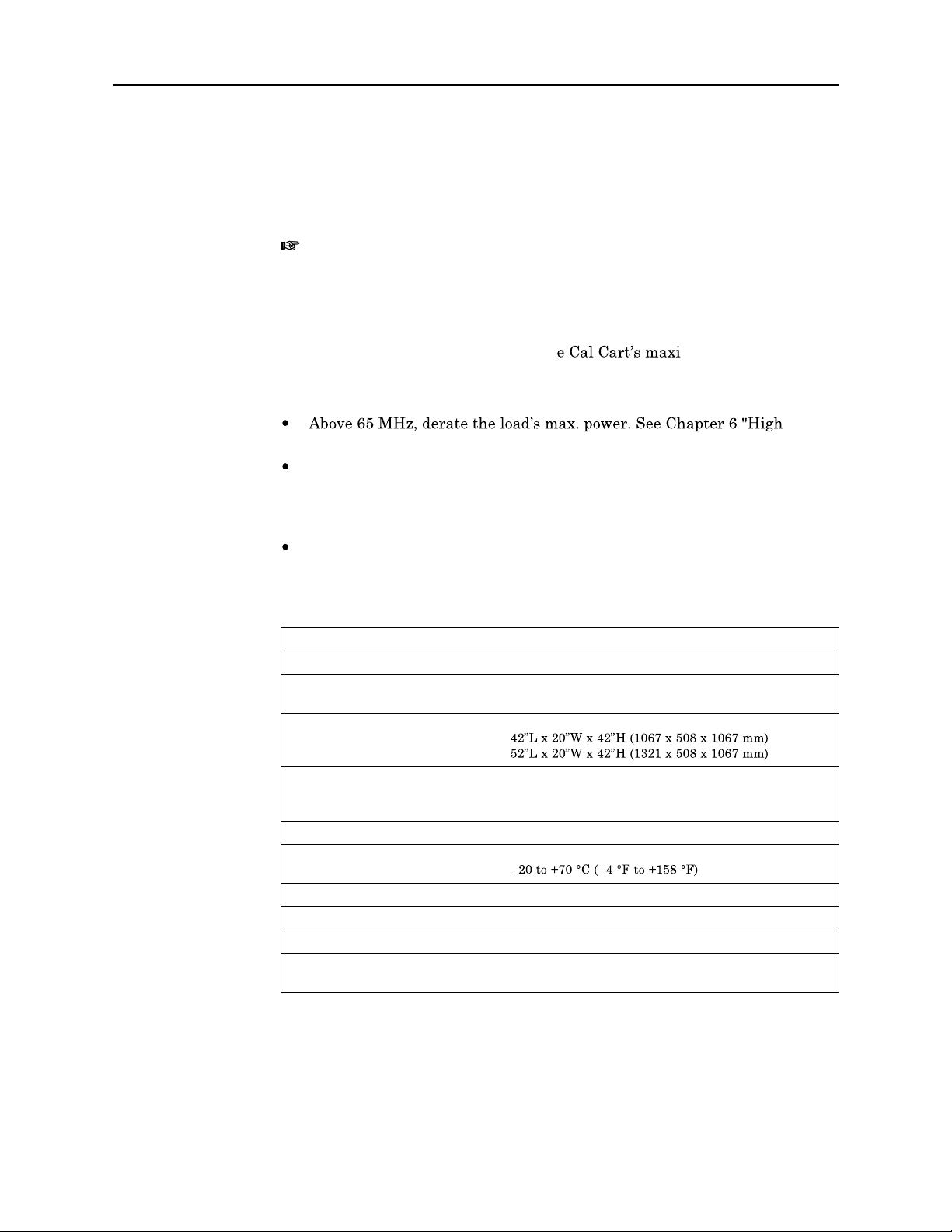
Bird 4421 RF Power Meter
Specifications, Cal Cart
To determine the model numbers of th
model number breakdown on page viii. Fo
e Cal Cart components, refer to the
r load specifications, refer to the
load manual included.
Note:
models. Refer to the model number breakd
Certain sensors or connectors ma
y be incompatible with some
own on page viii for a list of avail-
able components, or contact Customer Service.
Max. Power
Under normal operating conditions, th
MINIMUM of the max. power of the sens
or and the max. power of the load.
The following modifiers apply:
Frequency Derating", page 57.
Due to the wide variety of availa
ble connectors, frequency range and
maximum power may be reduced. Insertion loss is specified with female N
connectors. Choose connectors appropri
ate for the frequency and power of
operation.
Derate RF power by 2.5% for every 305m (1,000 ft.) above 1,520m (5,000
ft.).
Bird Cal Cart
mum power is the
Frequency Range
Power Range
Connectors
Dimensions
Short Cart
Long Cart
Weight, Nominal
Short Cart
Long Cart
Temperature Range
Operating
Storage
Altitude
Humidity
Calibration Cycle, Nominal
CE
Sensor dependent, 30 MHz max.
Dependent on sensor, sensor connectors, and loa d
Customer specified (See Chapter 6 "Ava ilable
Connectors", page 59)
175 lbs. (80 kg)
290 lbs. (114 kg)
0 to +35 °C (32 to +95 °F)
1520 m (5000 ft.)
85% non con densing max
1 year
CE Compliant. Refer to Declaration of Conformity for
specific standa rds.
50
Page 63
Maintenance
Specifications, 4
421 Power Meter
Frequency Range
Power Range
VSWR Display
Return Loss Display
Display Accuracy
AC Power
Batteries
Battery Life
Battery Charger
Display
Optional Interfaces
Fuse Rating
115 Vac
230 Vac
CE
Humidity
Altitude
Temperature Range
Operating
Storage
Dimensions
Weight, Nominal
Bird 4421 RF Power Meter
Sensor dependent
Sensor dependent
0 to 40 dB max
± 1 on least significant digit
115/230 Vac @ 50/60 Hz; 60 W
8 Nickel Metal Hydride 1.2 v cells, rechargeable
Approximately 8 hours continuous usage
Built-in ba t t ery charger. Drained batteries require
approximately 28 h ou r s to recharge.
LCD, 4½ digit display. Indicates mode, mea surement
units, battery condition , remote status, and signal
increase /decrease. Self con t a ined backlight.
IE E E-488 GPIB
RS-232
IE C (5 x 20 mm) Time Lag Type T
T630 m A
T315 m A
CE Compliant. Refer to Declaration of Conformity for
specific standa rds.
95% ma x. (noncondensing)
Up to 10,000 feet (3,000 m)
0 to 50 °C (32 to 122 °F)
9.5 lbs. (4.3 kg)
51
Page 64
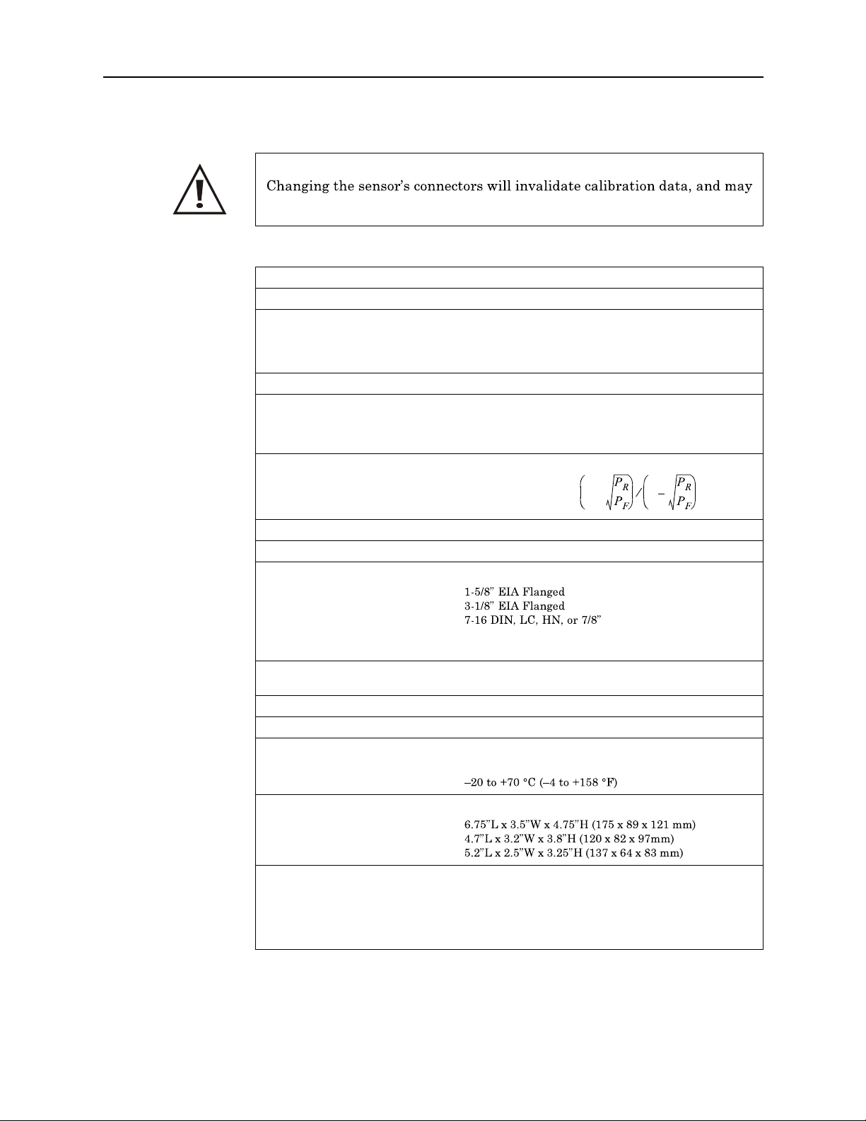
Bird 4421 RF Power Meter
Specifications, Power Sensors
CAUTION
reduce the maximum powe
Specifications Common to all Sensors
Impedance, Nominal
Max. Allowable Terminating VSWR
Calibration Technique
Calibration Cycle, Nominal
Accuracy, Reflected
Accuracy, VSWR
Sampling Rate, Nominal
Operating Power
Connectors
4028B10M
4028C10M
4028A Series
All other models
CE
Humidity, Max.
Altitude, Max.
Temperature Range
Operating
Storage
Dimensions
4028B10M
4028A Series
All other models
Weight, Nominal
4028B10M, 4028C10M
4028A2M, 3M, 4M, 10M, and
25M
All other models
r rating of the unit.
50 ohm s
2.00:1
Frequen cy-specific calibra t ion fa ct ors stored in
nonvolatile memory in each sensor.
Sensor output corrected for fr equ ency and temperature
within specified ranges.
6 months
Calculated from FWD accuracy and FWD power
RFL Accuracy FWD Accuracy
Calculated from FWD and RFL power
VSWR 1
2 readin gs/second
Su pplied by power meter via sensor cable
Customer specified from QC list, appropria te for
frequen cy an d power.
CE Compliant. Refer to Declaration of Conformity for
specific standa rds.
95% (n on con densing)
10,000 feet (3,000 m)
0 to 50 °C (32 to 122 °F)
5 lb. 2 oz. (2.33 kg)
3 lb. 5 oz. (1.5 kg)
1 lb. 13 oz. (0.8 kg)
=
------
+ 1
FWD Power
---------------------------------
+=
Directivity 10/
10
------
52
Page 65
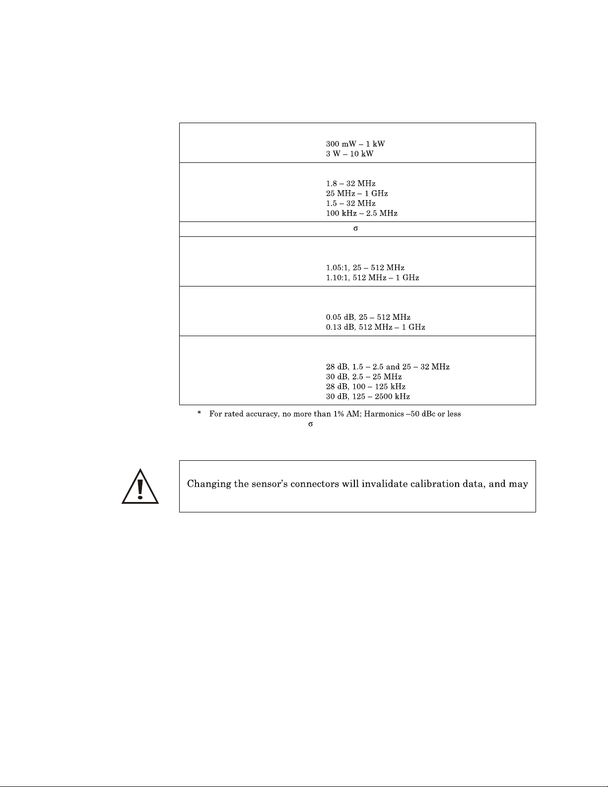
Maintenance
RF Power Range
4021, 4022
4024, 4025
Frequency Range
4021
4022
4024
4025
Accuracy, Fwd, Best Case
VSWR, Max.
4021, 4024, 4025
4022
Insertion Loss, Max.
4021, 4024, 4025
4022
Bird 4020 Series RF Power Sensors
*
± 3% (1 )
1.05:1
0.05 dB
Directivity, Min.
4021, 4022
4024
4025
Derate accuracy by 3.0% (1
30 dB
) below 15 °C and above 35 °C
CAUTION
reduce the maximum powe
r rating of the unit.
53
Page 66
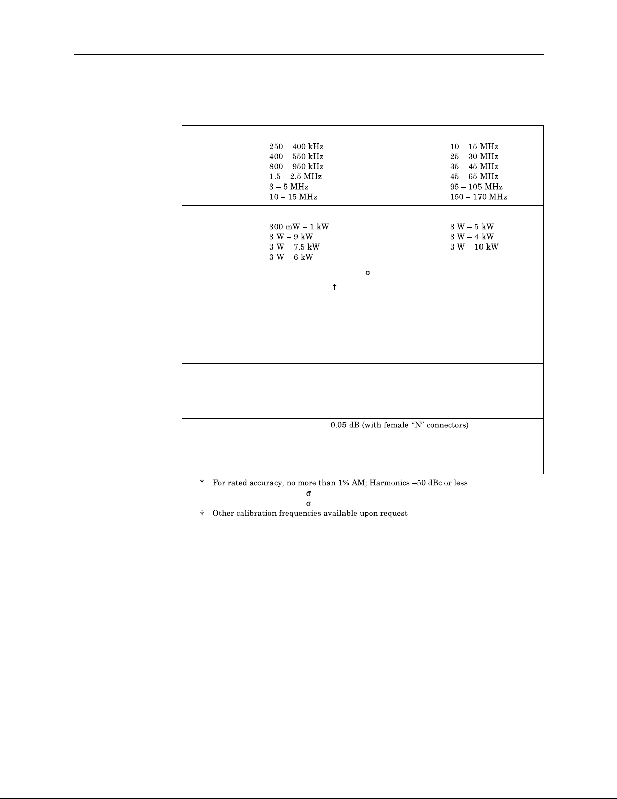
Bird 4421 RF Power Meter
Bird 4027A Series RF Power Sensors
Frequency Range
4027A250K
4027A400K
4027A800K
4027A2M
4027A4M
4027A10M
RF Power Range
4027A12M
4027A25M
4027A35M
4027A60M
Accuracy, Fwd, Best Case
Calibration Frequencies, Typical (MHz)
4027A250K
4027A400K
4027A800K
4027A2M
4027A4M
4027A10M
Calibration Power, Typical
4027A12M
All other models
VSWR, Max.
Insertion Loss, Max.
Directivity, Min.
4027A12M
All other models
*
0.25, 0.40
0.40
0.90
1.8, 2.0, 2.17
4.0, 5.0
10.0, 13.56, 15.0
± 1.0% (1 )
700 W
1.7 kW
1.05:1
30 dB
28 dB
4027A12M
4027A25M
4027A35M
4027A60M
4027A100M
4027A150M
4027A100M
4027A150M
All other models
4027A12M
4027A25M
4027A35M
4027A60M
4027A100M
4027A150M
10.0, 13.56, 15.0
25.76, 27.12, 28.48
40.68
55.0, 60.0
95.0, 100.0
162.0
54
Derate accuracy by 1% (1
Derate accuracy by 1% (1
) outside cal. power or cal. frequency
) below 15 °C and above 35 °C
Page 67
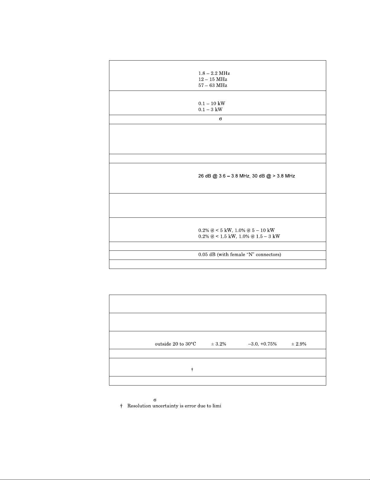
Maintenance
Bird 4027F Series RF Power Sensors
Frequency Range
4027F2M
4027F10M
4027F60M
RF Power Range
4027F2M, 4027F10M
4027F60M
Accuracy, Fwd, Best Case
Calibration Frequencies, Typical
4027F2M
4027F10M
4027F60M
Calibration Power, Typical
Harmonic Rejection, Min.
4027F2M
4027F10M
4027F60M
Low Frequency Rejection, Min.
4027F10M
4027F60M
Max Error Induced by 10% AM
4027F2M, 4027F10M
4027F60M
VSWR, Max.
Insertion Loss, Max.
Directivity, Min.
± 1.0% (2 )
*
1.8, 2.0, 2.17 MHz
12.0, 12.5, 13.56, 14.0, 15.0 MHz
57.0, 58.5, 60.0, 61.5, 63.0 MHz
1.7 kW
30 dB @ > 25 MHz
30 dB @ > 114 MHz
30 dB @ < 1 MHz
30 dB @ < 15 MHz
1.05:1
28 dB
* Oth er calibr a tion frequencies availa ble upon request
Uncertainty Budget, 4027F Series
Frequency
Error...
Power
Linearity...
Temperature
at cal freq ± 0.1% ± 0.1% ± 0.1%
not at cal freq ± 0.5% ± 1.5% ± 0.5%
at cal power ± 0.1% ± 0.1% ± 0.1%
not at cal power ± 1.0% ± 0.5% ± 1.0%
within 20 to 30°C ± 0.65% ± 0.6% ± 0.5%
*
4027F2M 4027F10M 4027F60M
Uncert...
Calibr at ion Uncertainty ± 0.6% ± 0.6% ± 0.6%
Resolution
Uncert...
at cal power ± 0.06% ± 0.06% ± 0.06%
not at cal power
± 0.34% ± 0.34% ± 0.34%
Other sources of error ± 0.4% ± 0.5% ± 0.6%
Best Ca se RSS Uncertain t y ± 1.0% ± 1.0% ± 1.0%
* All values 2
ted display digits. Actual uncertainty can
be calculated as
± (1 in least significant digit) / Reading
For a 3.5-digit display, worst case is at
uncertainty is ± 1W out of 300 or 0.34%. For
300W. Least significant digit is one watt,
a 4.5-digit display, least significant digit
is 0.1W, so the uncertainty is 0.034%
55
Page 68
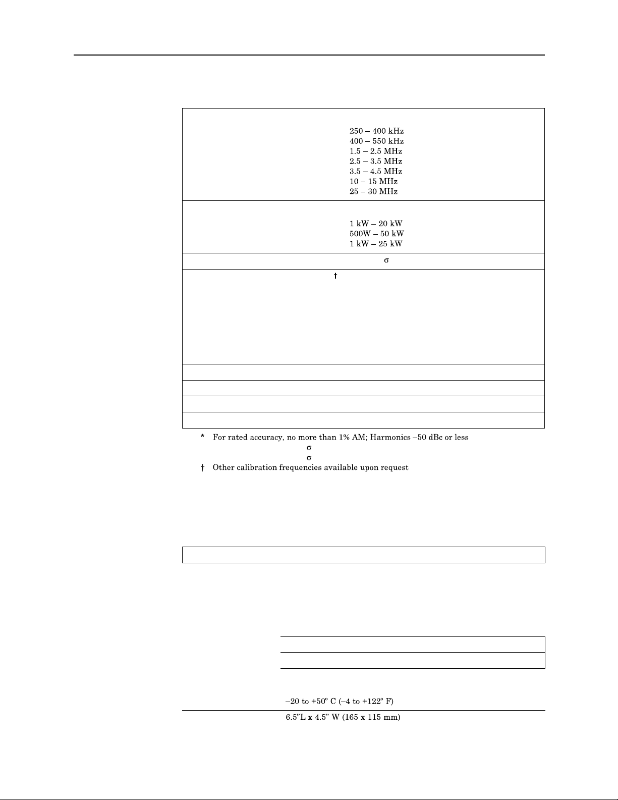
Bird 4421 RF Power Meter
Bird 4028A and 4028B Series RF Power Sensors
Frequency Range
4028A250K
4028A400K
4028A2M
4028A3M
4028A4M
4028A10M, 4028B10M, 4028C10M
4028A25M
RF Power Range
4028A250K, 4028A400K
4028C10M
All other models
Accuracy, Fwd, Best Case
Calibration Frequencies, Typical (MHz)
4028A250K
4028A400K
4028A2M
4028A3M
4028A4M
4028A10M, 4028B10M, 4028C10M
4028A25M
Calibration Power, Typical
VSWR, Max.
Insertion Loss, Max.
Directivity, Min.
*
± 2.0% (2 )
0.25, 0.40
0.40
1.8, 2.0, 2.17
2.5, 3.2, 3.5
3.5, 4.0
10.0, 13.56, 15.0
25.76, 27.12, 28.48
3.5 kW
1.05:1
0.05 dB (with female 7-16 DIN connectors)
28 dB
Derate accuracy by 2% (2
Derate accuracy by 2% (2
Specifications, RS-232 Interface
Logic Levels
Modes of Operation
Talk Always
Addressable
Connector RS-232 Interface Type
Humidity, Max
Altitude, Max
Temperature Range
Operating
Storage
Dimensions
) outside cal. power or cal. frequency
) below 15 °C and above 35 °C
RS-232 Interface Module
Meets all EIA Standa rd RS-232-C specifications
Switch and bus selectable
Allows the 4421 to send to the bus keyboard-initiated
measurements only
Allows the 4421 to be commanded by an RS-232 interface controller
95% (n on -condensing)
10,000 feet (3,000 m)
0 to 50º C (32 to 122º F)
56
Page 69
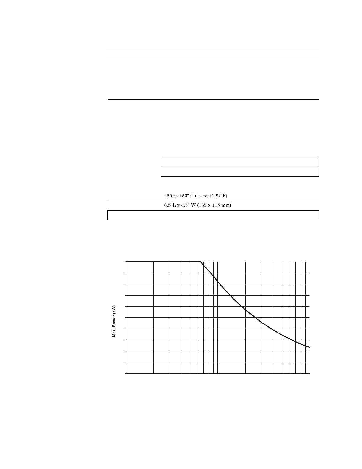
Maintenance
Weight
Specifications, IEEE
Logic Levels
Modes of Operation
Connector Standard IEEE-488 bus type
Humidity, Max
Altitude, Max
Temperature Range
Dimensions
Weight, Nominal
0.5 lbs (0.23 kg) nominal
-488 GPIB Interface
Meets all IEE E Standar d 488-1978 specifica tions
Switch and bus selectable
Talk Only
Addressable
Operating
Storage
Allows the 4421 to send to the bu
only
Allows the 4422 to be addressed as t alker or listener under the
command of an IEEE-488 bus controller
95% (non-con densing)
10,000 feet (3,000 m)
0 to 50º C (32 to 122º F)
0.5 lbs (0.23 kg)
IEEE-488 Interface
s keyboard-initiated measurements
High Frequency Derating
Load Derating Above 65 MHz
5 & 10 kW Loads
10
9
8
7
6
5
4
3
2
1
0
10 100 1000
Frequency (MHz)
57
Page 70
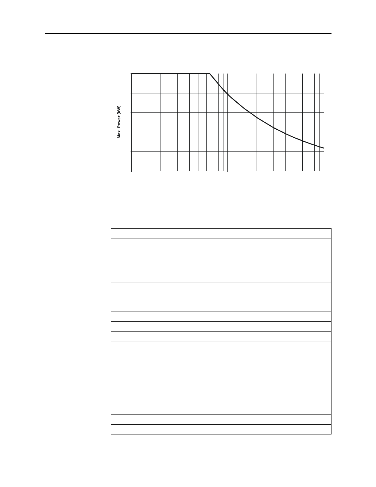
Bird 4421 RF Power Meter
Load Derating Above 65 MHz
1 & 2.5 kW Loads
2.5
2.0
1.5
1.0
0.5
0
10 100 1000
Frequency (MHz)
Replacement Parts
Description Qty Part Number
Fuse, IE C (5 x 20 mm) Tim e Lag Type T
Cord, AC Power
Plug, 115 Va c 1
Cable, Sensor 1
Grommet
Cordreel
Casters
Handle
IE E E-488 Bus Inter face Module 1
Cable, IEEE-488
RS-232 Bus Interface Module 1
Cable, RS-232
Null Modem Kit (RS-232 only) 1
Panel Mount Kit 1
Battery, C size, NiMH 8
115 Vac, T630 mA
230 Vac, T315 mA
115 Vac
230 Vac H a rm on ized
2 m
1 m
10 ft.
5 ft.
1
5A2257-10
5A2257-7
1
5-1286
5A2416
5A2626
4421-038
1
1
4
1
4421A372
4421A383
4421A384
4421A385
4421-489-2
1
5-1317-2
5-1317-1
4421-233-1
1
5-1662-2
5-1662-1
4380-250
4421-250
5A1230
58
Page 71
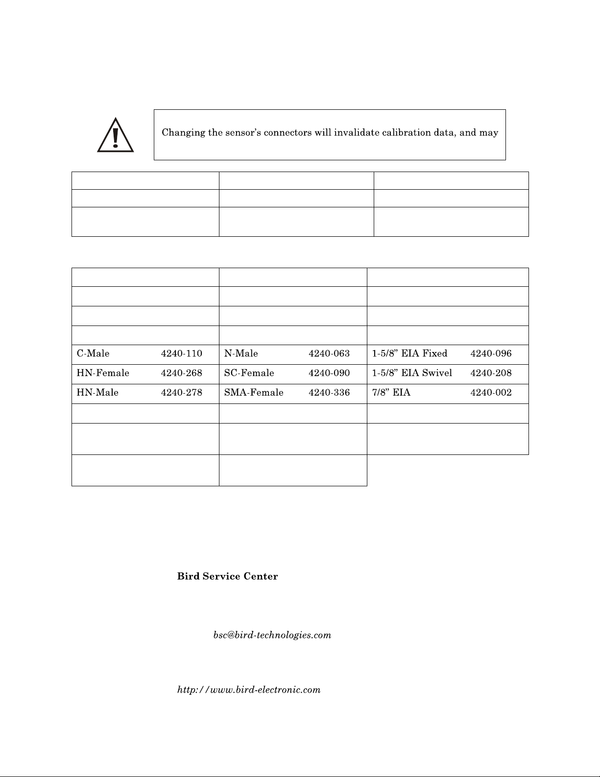
Maintenance
Available Connectors
CAUTION
reduce the maximum powe
Connector Part Number Connector Part Number Connector Part Number
HN (F)
LC (F)
Connector P/N Connector P/N Connector P/N
BNC-Female 4240-125 LT-Female 4240-018 Mini UHF-Female 4240-346
BNC-Male 4240-132 LT-Male 4240-012 UHF-Female 4240-050
C-Female 4240-100 N-Female 4240-062 UHF-Male 4240-179
LC-Female 4240-031 SMA-Male 4240-334 TNC-Female 4240-156
4240-268
4240-031
N (F)
7/16 J ack, IEC
Type 169-4
4240-062
4240-344
r rating of the unit.
TRU 6934 (F)
TRU 7958 (F)
4240-371
4240-372
LC-Male 4240-025 7/16 Jack, IEC
Type 169-4
Open Term.
# 10-32 Nut
4240-080 7/16 Plug, IEC
Type 169-4
Customer Service
If you need to return th
for a return authorization. All instrume
and to the attention of Bird Service Center.
30303 Aurora Road
Cleveland (Solon), Ohio 44139-2794
Phone: (440) 519-2298
Fax: (440) 519-2326
E-mail:
For the location of the sales office neares
site at:
4240-344 TNC-Male 4240-160
4240-363
e unit for any reason, contac
nts returned must be shipped prepaid
t you, give us a call or visit our Web
t the Bird Service Center
59
Page 72

Bird 4421 RF Power Meter
60
Page 73

Limited Warranty
All products manufa ctured by Seller are warranted to be free from defects in material and
workmanship for a period of one (1) year, unless otherwise specified, from date of shipment and to
conform to applicable specifications, drawings, bluepr
under these warranties shall be to issue credit, repair or replace any item or part thereof which is
proved to be other than as warranted; no allowanc
replacement of parts, adjustment or repairs, or any other work, unless such charges are authorized
in advance by Seller.
be defective in material or workma nship or not to conform to
specifications, drawings, blueprints and/or samples, Seller shall, upon prompt notice thereof, either
examine the products where they are located or issue shipping instructions for return to Seller
(transportation-charges prepaid by Buyer). In the event any of our products are proved to be other
than as warranted, transportation costs (cheapest wa
Seller and reimbursement or credit will be made for amounts so expended by Buyer. Every such
claim for breach of these warranties sha ll be deemed to be waived by Buyer unless made in writing
within ten (10) days from the date of discover y of the defect.
e shall be made for any labor charges of Buyer for
The above warranties shall not extend to any produc
any misuse or neglect, damaged by
by the performance of repairs or alterations outsid
parts thereof furnished by Buyer or acquired from others at Bu
specifications. Routine (regularly required) calibration
to other equipment and parts manufactured by others except to the extent of the original
The obligations under the foregoing warran ties are limited to the precise terms thereof. These
warranties provide exclusive remedies, expressly in lieu of all other remedies including claims for
special or consequential damages. SELLER NEITHER MAKES NOR ASSUMES ANY OTHER
WARRANTY WHATSOEVER, WHETHER EXPRESS, STATUTORY, OR IMPLIED, INCLUDING
WARRANTIES OF MERCHANTABILITY AND FITNESS, AND NO PERSON IS AUTHORIZED
TO ASSUME FOR SELLER ANY OBLIGATION OR LIABILITY NOT STRICTLY IN
ACCORDANCE WITH THE FOREGOING.
accident, rendered defective by reas
Special Lifetime Warranty - Se
Series 4027F, and Series
In addition to its standard warranty, the Bird Electronic Corporation warrants its Series 4020,
Series 4027A, Series 4027F, and Series 4028 Thruline® Power Sensor Heads for lifetime to original
purchaser. This extended warranty is against burnout. For the warranty to apply, the Sensor Head
must be used with the correct Bird Electronic
of the Sensor must not be exceeded, the Sensor RF circuit must be properly terminated and the
Sensor not subjected to physical abuse.
ts or parts thereof which have been subjected to
on of improper installation or
e of our plant, and shall not apply to any goods or
is not covered under this limited warranty. In
re of tubes, transistors,
fuses and batteries, or
ries 4020, Series 4027A,
4028 Power Sensor Head
Corporation Display Unit, the maximum power rating
Bird Electronic Corporation, a t its option, will repair or replace the defective Sensor at its world
Headquarters at 30303 Aurora Road, Solon, Ohio 44139.
The customer is responsible to pay transport ation charges to return the defective sensor to Bird.
Page 74

DECLARATION OF CONFORMITY
Manufacturer: Bird Electronic Corporation
30303 Aurora Road
Cleveland, Ohio 44139-2794
Product: 4421 Power Meter and 402X
Models: Power Meter: 4421
Directional Power Sensors:
4021 4027A250K 4028A250K
4022 4027A400K 4028A400K
4024 4027A800K
4025 4027A2M 4027F2M 4028A2M
4027A4M 4028A4M
4027A10M 4027F10M 4028A10M 4028B10M 4028C10M
4027A12M 4028A25M
4027A25M
4027A35M
4027A60M 4027F60M
4027A100M
4027A150M
The undersigned hereby declares, on behalf of Bird
the above referenced products, to which this de
provisions of the following standards.
In accordance with EMC Directive (89/336/EEC)
Directional Power Sensors
4028A3M
Electronic Corporation of Cleveland, Ohio, that
claration relates, are in conformance with the
European Standard EN 61326-1:1997 (Addendums A1
for Electrical Equipment for Measur
European Standard EN 55011:1988 - Emissions, Class A
European Standard EN 61000-6-2 - Generic Immunity Standard
In accordance with Low Voltage Directive (
1993
European Standard EN 61010-1:2001 - Safety Re
Measurement, Control
The technical documentation supporting compliance
Electronic Corporation, 30303 Aurora Road, Cleveland, Ohio 44139.
and Laboratory Use
ement, Control and Laboratory Use
73/23/EEC), 1973 including Amendment (93/68/EEC),
quirements for Electrical Equipment for
with these directives is maintained at Bird
:1998 and A2:2001) - Safety Requirements
 Loading...