

Page 1
CAUTION – RISK OF SHOCK –
Disconnect Power at the main circuit breaker panel or main fuse
box before starting and during the installation.
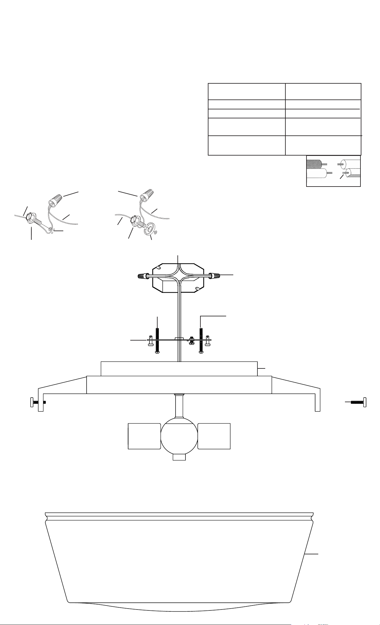
1) Get item-A, mounting hardware and find the appropriate
threaded holes on mounting strap. Assemble mounting
screws into threaded holes.
2) Attach mounting strap to outlet box with the two (2) strap
mounting screws.. Mounting strap can be adjusted to suit
position of fixture.
3) Grounding instructions: (See Illus. A or B)
A) On fixtures where mounting strap is provided with a
hole and two raise dimples. Wrap ground wire from
outlet box around green ground screw, and thread into
hole.
B) On fixtures where a cupped washer is provided. Put
ground wire from outlet box under cupped washer and
green ground screw and thread screw into hole in
mounting strap.
If fixture is provided with ground wire. Connect fixture
ground wire to outlet box ground wire with wire connector,
after following the above steps. Never connect ground wire
to black or white power supply wires.
A
OUTLET BOX
GROUND
GREEN GROUND
SCREW
WIRE CONNECTOR
FIXTURE
GROUND
DIMPLES
OUTLET BOX
GROUND
GREEN GROUND
SCREW
B
FIXTURE
GROUND
CUPPED
WASHER
OUTLET BOX
4) Make wire connections. Reference chart below for correct
connections and wire accordingly.
Connect Black or
Red Supply Wire to:
Connect
White Supply Wire to:
Black White
*Parallel cord (round & smooth) *Parallel cord (square & ridged)
Clear, Brown, Gold or Black
without tracer
Insulated wire (other than green)
with copper conductor
Clear, Brown, Gold or Black
with tracer
Insulated wire (other than green)
with silver conductor
*Note: When parallel wires (SPT I & SPT II)
are used. The neutral wire is square shaped
or ridged and the other wire will be round in
shape or smooth (see illus.)
Neutral Wire
5) Push the B-canopy to ceiling, carefully passing mounting
screws through holes, rotate canopy and tighten mounting
screws.
6) Insert recommended bulb (not included).
7) Place glass up into canopy, insert and tighten the (3) Cthumb screws. (DO NOT over-tighten) Installation is now
complete.
MOUNTING
GEMSTRAP
WITH
GROUND SCREW
STRAP
SCREWS
WIRE
CONNECTOR(S)
MOUNTING
SCREWS
B
C
D
 Loading...