

Page 1
Installation Guide
ToolsRequired: Flatheadscrewdriver, Phillipsscrewdriver,pliers,wire cutters,wire strippers,electricaltape, safetyglasses.
LightSource:
FixtureHangingHeight:
EstimatedAssembly Time:
Preparation:
present.Ifany partsare missingordamaged, donot attempttoassemble, install,or operatethefixture. MissingParts? Contactyouroriginal placeof
purchase.
Warnings and Cautions
Turn off electricity at circuit breaker or main fuse box before installation. Consult a licensed electrician if in doubt.
These instructions are provided for your safety. It is very important you read them completely before installing the fixture. We strongly
recommend that a licensed, professional electrician perform the installation.
Disconnect fixture from power source before replacing bulbs. Make sure bulbs are given sufficient time to cool before removal.
(3)B10Candelabra Basebulbs 60WMaximum,bulb notincluded.
MinimumHangingHeight is15.5”,Maximum HangingHeightis 51.5”.
30-45minutes
Identifyandinspect allparts beforebeginninginstallation. Checkpackage contentlistand diagramsbelow toensureall partsare
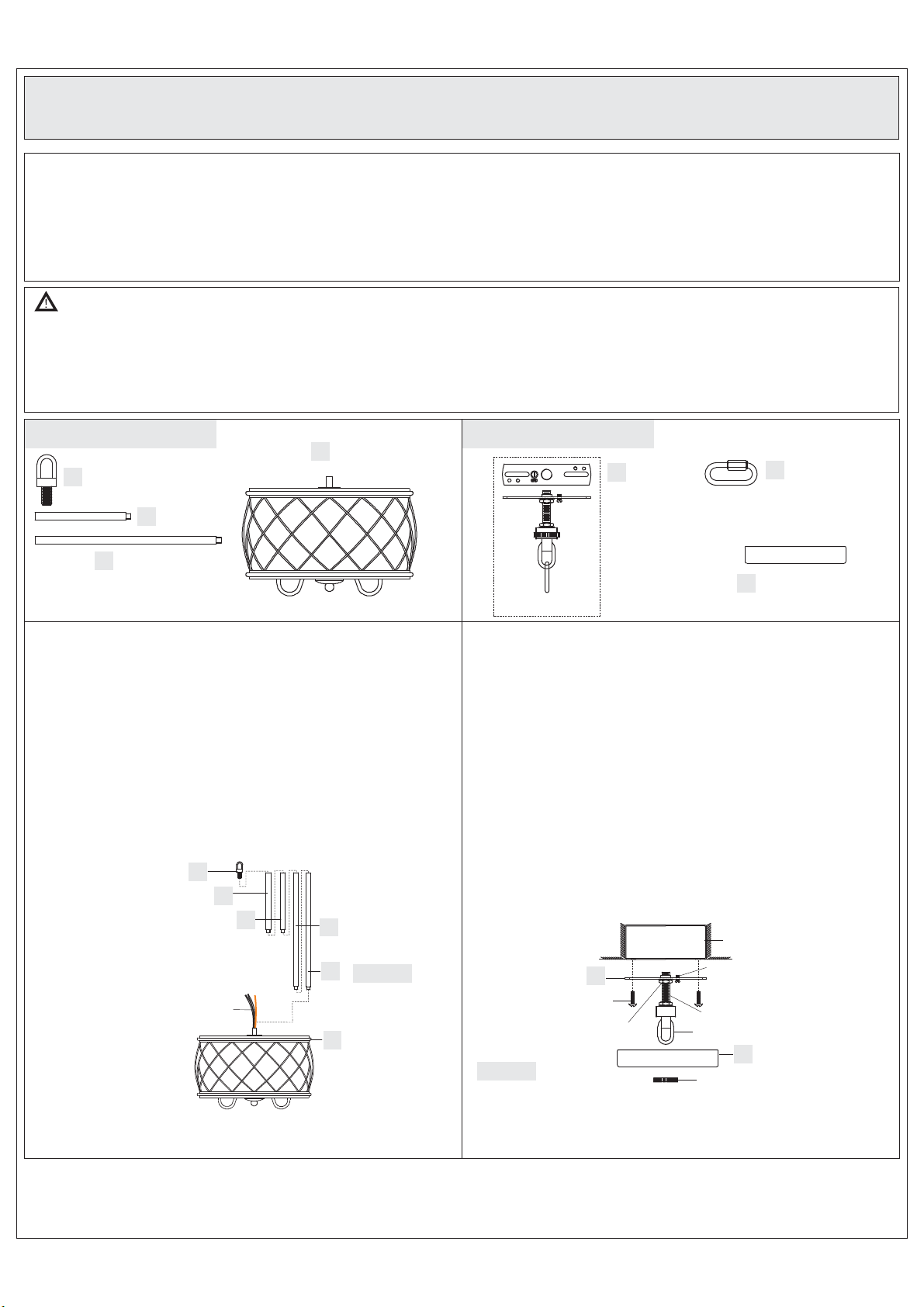
Package Contents
Fixture Loop
A
x1
6” Rod
B
x2
12” Rod
C
x2
STEP 1 Install Fixture Loop and Rods to Fixture Body-
A. Determine the Rods (B/C) to be assembled to the Fixture Body
according to your hanging height.
B. Pass the supply wires and ground wire through the chosen rods (B/C)
and the Fixture Loop (A). Thread the Fixture Body (D), the chosen
Rods (B/C) and the Fixture Loop (A) together. Hand tighten until snug.
Suggested rods for Ceiling height :
8’ ceiling : use (1) 6” rod and (1) 12” rod
9’ ceiling : use (1) 6” rod and (2) 12” rod
A
B
B
Fixture Body
D
x1
C
Hardware Contents
Crossbar
AA
Assembly
x1
CC
STEP 2 - Install the CrossbarAssembly to Outlet Box andAdjust
the length of the Nipple
A. Attach the Crossbar Assembly (AA) to the Outlet Box with the head of
the Green Ground Screw facing you. Secure it with Outlet Box Screws
(not included), tighten until snug
B. Adjust the hex nut and lock washer underside of the crossbar to the
middle of the nipple.
C. Remove the canopy lock ring from the canopy chain loop. Place the
Ceiling Canopy (CC) over the canopy chain loop against the ceiling to
determine the correct position of the nipple. Thread the canopy lock
ring onto the canopy chain loop. Adjust the nipple to allow the Ceiling
Canopy (CC) to rest against the ceiling when held in place by the
canopy lock ring.
D. Remove the canopy lock ring and the Ceiling Canopy (CC). Tighten
the lock washer and the hex nut against the crossbar to secure in
place.
.
Outlet Box
Quick Link
BB
x1
Ceiling Canopy
x1
Supply
Wires and
Ground Wire
C
D
Figure 1
1of2
Outlet Box Screw
(not included)
Figure 2
AA
Hex Nut and
Lock Washer
Green Ground Screw
Nipple
Canopy Chain Loop
CC
Canopy Lock Ring
Page 2
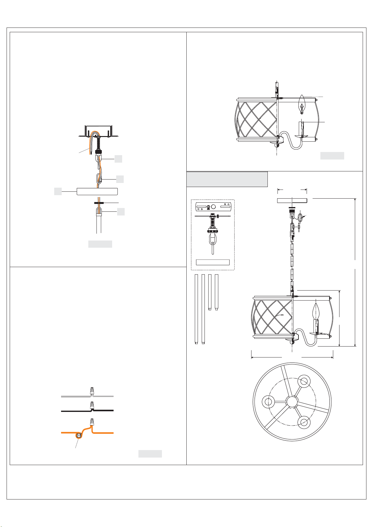
STEP 3 - Install the Fixture Chain and Ceiling Canopy
A. Pull the supply wires and ground wire through the Canopy Lock
Ring and the Ceiling Canopy (CC) in order.
B. Connect the Fixture Loop (A) to the Canopy Chain Loop by using the
Quick Link. The fixture will now hang safely.
C. Feed the Supply Wires and Ground Wire through the Canopy Chain
Loop and Nipple into the Outlet Box. Cut the wires leaving
approximately 8” of wire extending from the Outlet Box.
D. Go to Step 4 for wire connections and follow the directions. Return
to Step E in this step when complete with Step 4.
E. Raise the Ceiling Canopy (CC) and Canopy Lock Ring up the Quick
Link and over the Canopy Chain Loop. Tighten the Canopy Lock
Ring onto the Canopy Chain Loop until tight.
Supply
Wires and
Ground Wire
AA
STEP 5 - Install the Bulb
A. Insert the bulb onto socket and screw snugly into place.
Your fixture is now assembled and ready to use. Enjoy!
Bulb
(not included)
Socket
Figure 5
BB
CC
Canopy Lock Ring
A
Figure 3
STEP 4 - Making the Wire Connections
A. Wrap bare or green ground wire around green ground screw on the
crossbar, no less than 2 inches from the end of the wire. Tighten the
green ground screw.
B.
Use standard wire connectors (not included) to make all wire
connections. Twist connectors until wires are tightly joined together.
Wrap each connection with approved electrical tape and carefully
stuff all the connected wires into outlet box.
Note: If the electrical wire is going to be cut shorter than provided
you will need to identify the "L" line wire and the "N" neutral wire
before you cut the excess wire off. One is labeled N and the other
labeled L. To do this separate the "L" line wire and the "N" neutral
wire as far as you need to. Re-label the wire near where you want to
make the cut. Be sure to mark the wire on the side of the fixture and
not on the excess wire being cut and removed.
FINISH: PALLADIAN BRONZE
5” Dia.
51.5”
10.5”
15” Dia.
White wire
from outlet box
Black wire from
outlet box (or Red)
Bare, or Green
Ground wire
from outlet box
Green Ground Screw
on the Crossbar
White wire from fixture
identified with the Label “N”
Black wire from fixture
identified with the label “L”
Ground wire
from Fixture
Figure 4
NOTE: ALL DIMENSIONS ARE ROUNDED
UP TO THE NEAREST 1/4"
2of2
 Loading...