

Page 1
1
1
2
Mode
Sim1
Data
Sim2
1
2
Info
AC
AC
A1
11
22
A2
21
no
nc
common
14
31
12
no
nc
common
32
24
34
1
32
24
34
1
2
24
32
34
1
2
302111B
10/13
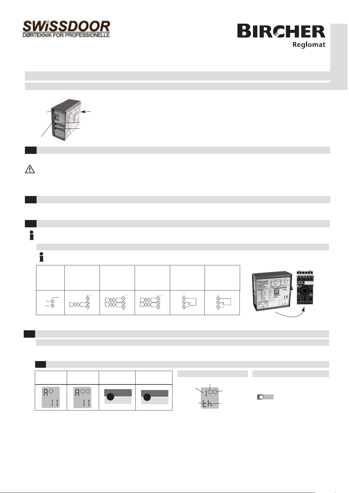
ProLoop2 (11-pin)
Loop detector for industrial doors and gates,
car parks and parking bollards
Translation of the original instructions
General
LCD display
Safety instructions
1
These devices and their accessories may only be operated in compliance with the operating instructions (intended use)!
These devices and their accessories may only be commissioned by trained and qualified personnel.
These devices may only be operated with the intended supply voltage and parameters.
If malfunctions occur that cannot be rectified, shut down the device and send it in for repair.
These devices are only allowed to be repaired by the manufacturer. Tampering and alterations are not permitted. This will invalidate all guarantee and
warranty claims.
Mechanical mounting in the switch cabinet
2
The 11-pin version of the ProLoop is mounted onto a mounting rail base (ES 12). This base is ordered and delivered separately as it is not included in the
scope of delivery.
Electrical connection
3
The loop connection wiring to the loop detector must be twisted at least 20 times per meter.
Please wire the device in accordance with the terminal assignment. Make sure the terminals are assigned correctly.
Terminal connection diagram, ES 12 base assignment
«Mode»-button
«Data»-button
Plug-in connection, 11-pin
Info LED
ENGLISH
Check the electrical connection (base assignment) when exchanging a loop detector from another manufacturer.
A:
Supply
voltage
connection
1)
Only applies to ProLoop2 with the designation «... .S.78. ... .»
Value and parameter setting options
4
B:
Loop connection
1-channel device
C1:
Loop connection
2-channel device
C21):
Loop connection
2-channel device
D:
Relay connection
output 1
E:
Relay connection
output 2
General
The settings of the ProLoop devices in this chapter are shown and explained for the 1-loop device. The settings for loop 2 of a 2-loop device should be
made using the corresponding method.
LCD display and controls
4.1
Standard display
1-loop device
Standard display
2-loop device
Control button Control button
Explanation of the LCD display Explanation of the LED
Function
Example:
Time
function set
Loop 1
Loop 2
Example:
Parameter
«h» set
Red & green: Start-up phase
Green: Operation
Red & green: Configuration
Flashing green: Loop activated
Flashing red: Error
Flashing
red + green: Simulation
1
Page 2
Loop
Relay
Loop
Relay
tt
Loop
Relay
tt
Loop
Relay
tt
Loop
Relay
tt
4.2
1
Mode
Sim1
1
1
2
Mode
Sim1
1
Mode
Sim1
2
Basic functions 0 (see Table 4.11a for settings)
Parameters
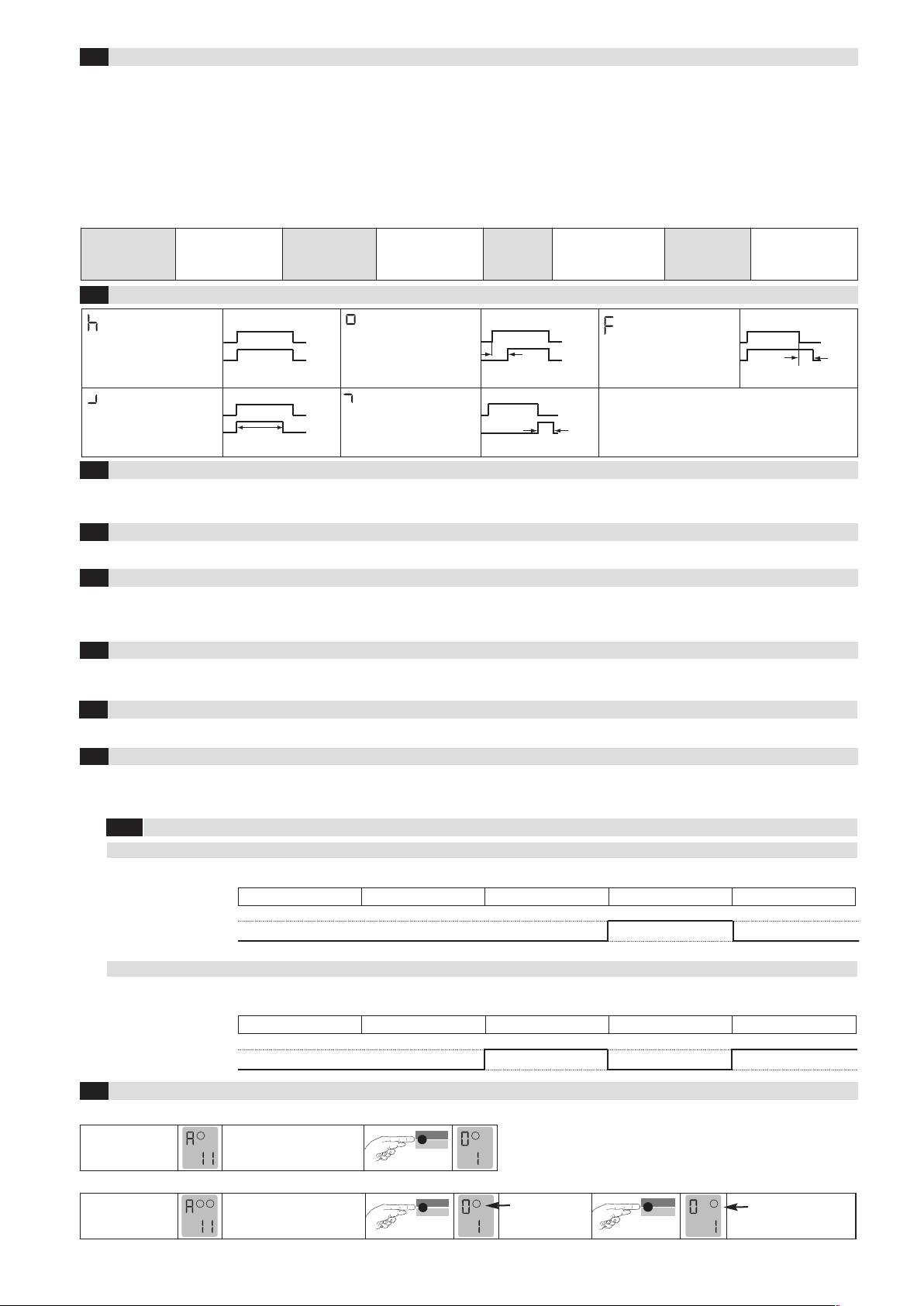
1: Door and gate The assigned output relay picks up when the loop is activated and drops out when the loop returns to a non-activated condition.
2: Barrier The assigned output relay picks up when the loop is activated and drops out when the loop returns to a non-activated condition.
3: Quiescent current The assigned output relay drops out when the loop is activated and picks up again when the loop returns to a non-activated condition.
4: Direction logic Output 1 switches if an object moves from loop 1 to 2. Output 2 switches if an object moves from loop 1 to 2. For a short time,
both loops must be activated. The output resets again when leaving the second loop. Both loops must have returned to a non-
activated condition for another direction detection.
0: Loop 2 Loop 2 can be deactivated in a 2-loop device.
Relay response to malfunctions (see chapter 6 Troubleshooting):
1.Door/gate
systems
Time functions 1, time unit 2 and time factor 3 (see Table 4.11a for settings)
4.3
The relay picks up when the
loop is activated and drops
out when the loop is exited.
A malfunction causes
the output relay to be
released. The alarm
relay drops out.
2. Barrier
A malfunction causes
the output relay to pick
up. The alarm relay
drops out.
On delay:
The relay picks up after the
time t when the loop is activated and drops out when
the loop is exited.
3. Quiescent
current
A malfunction causes the
output relay to be
released. The alarm relay
drops out.
Off delay:
The relay picks up when the
loop is activated and drops
out after the time t when the
loop is exited.
4. Direction logic
(2-loop device
only)
A malfunction causes
the output relays to be
released.
Activation pulse:
The relay picks up when the
loop is activated and drops
out again after the time t.
Sensitivity 4 (see Table 4.11a for settings)
4.4
Impulse by leaving the loop:
By leaving the loop,
the relay picks up after
the time t, relay drops out.
The sensitivity 5 (= Sensitivity) of the loop detector can be adapted in 9 stages: 51 = Lowest sensitivity, 59 = Highest sensitivity,
56 = Factory setting. The sensitivity setting depends on the frequencies (see chapter 4.6 Frequency).
4.5
Automatic Sensitivity Boost ASB 5 (see Table 4.11a for settings)
ASB (= Automatic Sensitivity Boost). ASB is required in order to be able to recognise trailer drawbars after activation.
4.6
Frequency 6 (see Table 4.11a for settings)
Four different frequencies F1, F2, F3, F4* can be set in order to avoid interference when using several loop detectors. These settings influence the
sensitivity (the sensitivity can be set in the range 1–7 for frequencies F1 to F3). F2 to F4 can be set for inductance < 150 µH and only F4 can be set for
inductance < 75 µH.
4.7
Direction logic7 (see Table 4.11a for settings)
The direction logic function can only be used with a 2-loop device. Direction logic must have been set in the basic function (see chapter 4.2). Detection
can be performed from: ➝ Loop 1 to loop 2 ➝ From loop 2 to loop 1 ➝ from both directions
4.8
Output 2 8 (see Table 4.11b for settings)
Output 2 can also be set as an alarm output.
4.9
Protection against supply voltage failure 9 (see Table 4.11a for settings)
Note: The set parameter values are preserved in the case of a mains failure - regardless of the «Protection against supply voltage failure» function.
P 1 = Protection against supply voltage tailure activated: The sensitivity is restricted to 1–5.
4 .9.1
Signal characteristics with protection against supply voltage failure active (Function 9 = 1)
For Activation (e.g. Barriers)
Basic function 0 = 2 Barrier systems
Output
Without power Initialisation Free Occupied Free
open (no)
closed (nc)
For Safeguarding (e.g. Barriers, bollards)
Basic function 0 = 3 Quiescent current
Output
Without power Initialisation Free Occupied Free
open (no)
closed (nc)
Changeover from operation to configuration mode
4.10
1- loop device
Display after start-up:
Touch the «Mode» button once
to change to configuration
mode
2- loop device
Display after start-up:
Back to automatic mode: Press «Mode»-button >1 second)
2
Touch the «Mode» button once
to change to configuration
mode
Loop 1 is
selected
Loop 2 is
selected
*factory settings
Page 3
1
Mode
Sim1
1
Mode
Sim1
1
Mode
Sim1
1
Mode
Sim1
1
Mode
Sim1
1
Mode
Sim1
1
Mode
Sim1
1
2
Mode
Sim1
1
Mode
Sim1
Mode
Sim1
1
Data
Sim2
Data
Sim2
Data
Sim2
Data
Sim2
Data
Sim2
Data
Sim2
1
1
1
1
2
2
1
1
1
1
1
1
1
1
1
1
1
1
1
1
1
1
1
1
1
2
1
2
1
2
2
2
2
P 1
1
Loop
Relay
tt
Loop
Relay
Loop
Relay
tt
Loop
Relay
tt
Loop
Relay
tt
Loop
Relay
tt
=
Notes
9
*factory settings
).
A0
=
5
(
parameter 5 must be set to off
If parameter
the output 2 becomes
With deactivation of Loop 2
device
with 2 loops and a 2-loop
can only be implemented
configurable g 8
set time.
the time factor gives the
The time unit multiplied by
Setting restrictions:
voltage failure (with P1):
rotection against supply
Value 1-5
The direction logic function
Loop 2 has to be
g Basic function
deactivated «0»
operating instructions
error: see chapter 6 of these
Possible displays in case of
Max. presence
when loop is exited
Time funct. pulse
deactivated: «0»
activated: «1»*
Loop 2
Only 2-loop device:
Activation
pulse loop
Direction logic
Off delay
Quiescent current
1 hour
1 minute
Frequency F3
Frequency F2
Loop 1 to loop 2
to loop 1
Output 2 is bound
slot 5
Error memory
slot 3
Error memory
slot 3
Error memory
Error memory slot 2
Button operation
On delay
Barrier systems
∞*
systems*
Door/gate
parameter
1 second*
0.1 second
not appear with
This display does
holding the «Data»
and 99 by touching or
Set value between 1
1*
not appear wih time
This display does
time function th (∞)
function th (∞)
by touching or holding
) and 9 (highest sensi.)
Set value betw. 1 (lowest
button
4*
= Sensitivity
5
Switched on
the «Data» button
Switched off*
Automatic Sensiti-
ASB stands for
Frequency F1
Frequency F4*
vity Boost
loop 1
Loop 2 to
ons*
Both directi-
only with a
This display appears
connected as
Output 2 is
switched off
Output 2 is
2-loop device
Switched on
an alarm output
failure:
Supply voltage
slot 1
Error memory
Bemerkung
1 = Output 2 active; 0 = Output 2 off; A = Output as alarm output
Parameter 8 is not possible and is not displayed
mode
Operating
Switched off*
Output 2
1 = Output 2 active; 0 = Output 2 off; A = Output as alarm output
–
1/0/A*
1/0*/A
functions
Button operation
Loop 2
–
active
deactivated
LCD
display
Configuration mode
ASB
4.11
Note on 2-loop device: After loop 1 has been set, the parameters for loop 2 are set (make the settings using the same procedure) and the settings are not shown in the table with the exception of the direction logic
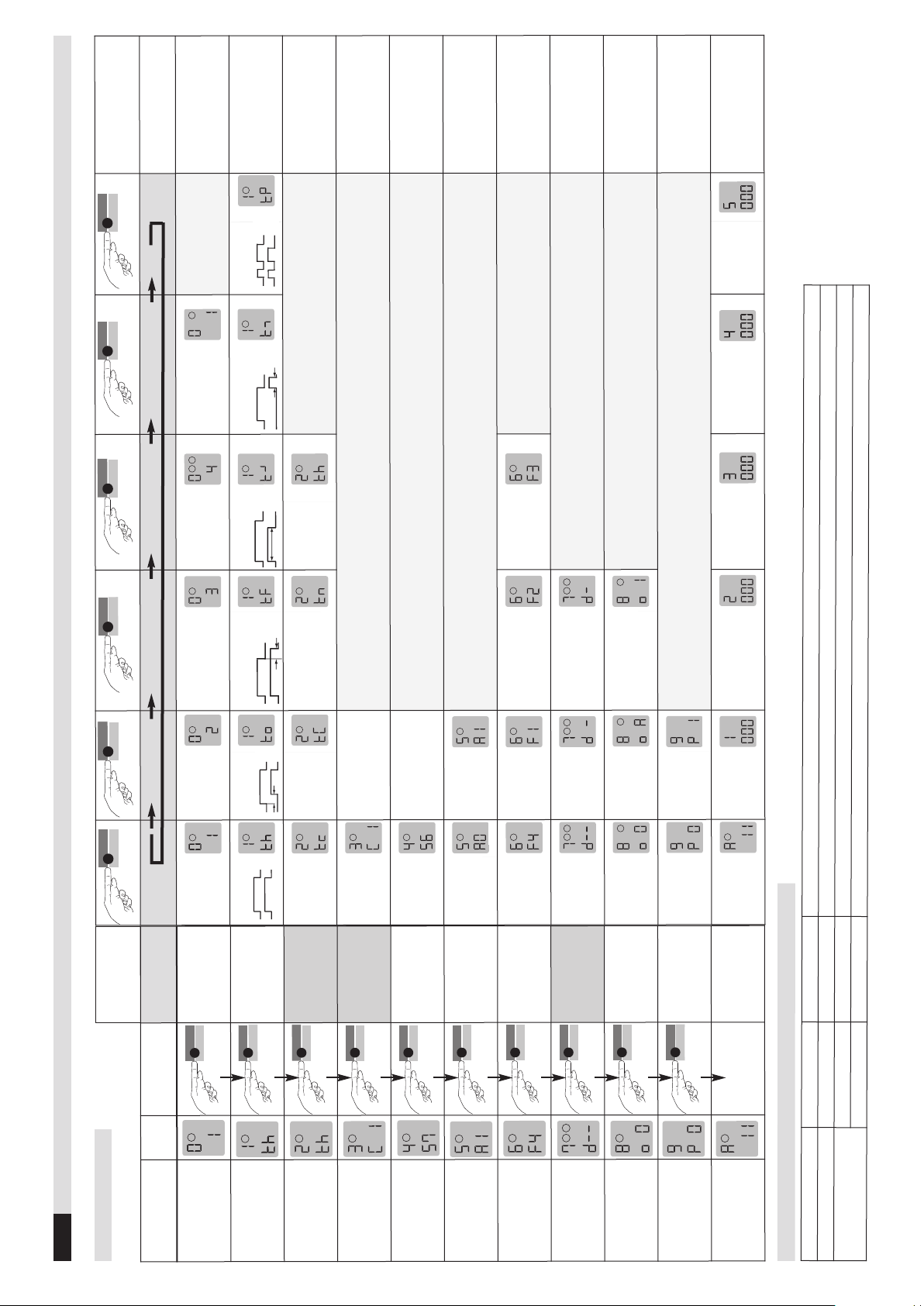
Table 4.1a Settings
Function
0 - Basic function
1 - Time function
2 - Time unit
3 - Time factor
4 - Sensitivity
Sensitivity Boost
5 - Automatic
6 - Frequency
7 - Direction logic
configuration
8 - Output 2
9 - Protection
voltage failure
against supply
A - Operating mode
Table 4.11b Addition to function 8 (configuration of output 2) and function 0
1-loop device, 2 relays
2-loop device, 2 relays
3
Page 4
Mode
Sim1
2 seconds
Data
Sim2
2 seconds
1
1
Data
Sim2
1
Mode
Sim1
2
Data
Sim2
2
Mode
Sim1
1
Data
Sim2
1
Mode
Sim1
2
Data
Sim2
2
Mode
Sim1
Data
Sim2
Mode
Sim1
1
Mode
Sim1
2
Mode
Sim1
2 seconds
1
2
Simulation mode
Mode
Sim1
2 Sekunden
Mode
Sim1
8 Sekunden
Data
Sim2
5
Changeover to simulations mode
Press «Sim1»
button
Press «Sim2»
button
Press «Sim2»
button
Press «Sim2»
button
Anmerkungen
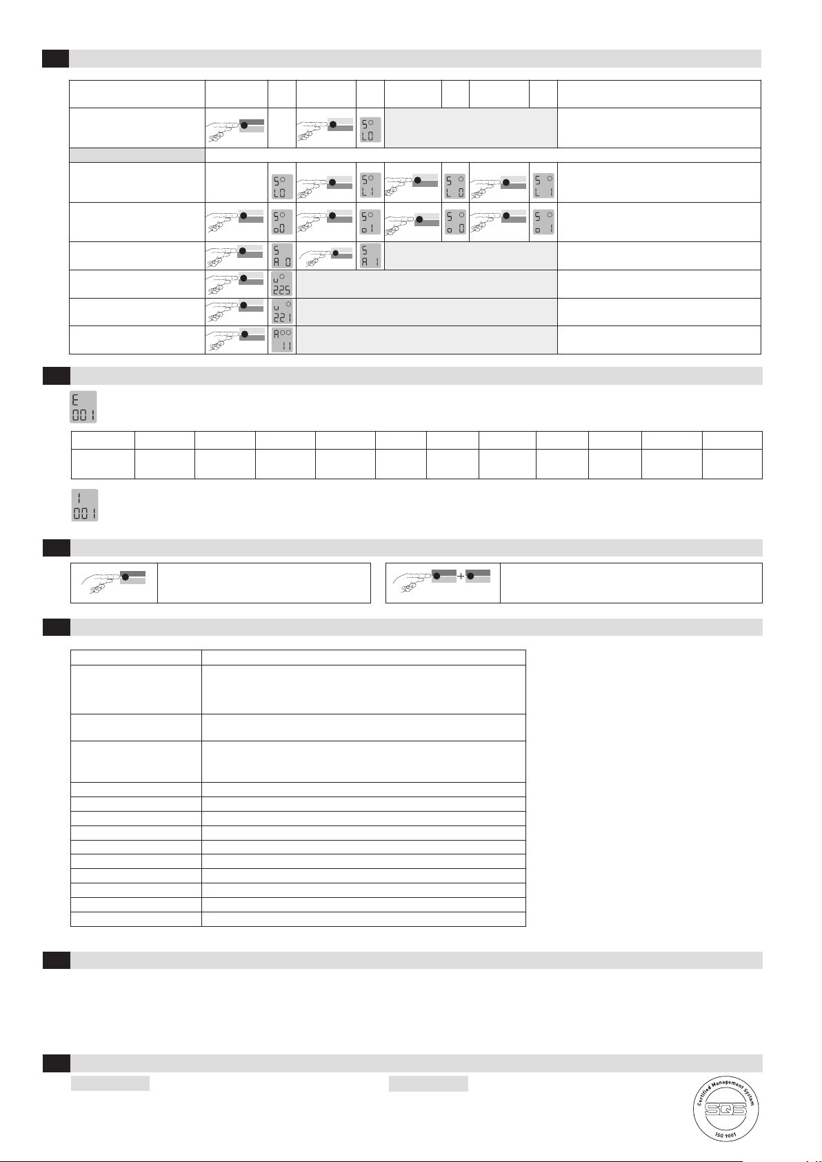
Changeover to simulation mode:
Press the Sim1 + Sim2 buttons
simultaneously for 2 seconds.
+
Simulation mode:
Activation of the loop
Activation of the output relay
Alarm output activation
Inductance of loop 1
Inductance of loop 2
Exiting simulation mode
Troubleshooting
6
L0 -No loop activation (time functions are active)
L1 -Loop activation (time functions are active)
- Loop 1 - Loop 2
00 - Activation of output
01 - Activation of output
- Loop 1 - Loop 2
A0 -Switch off alarm relay
A1 -Switch on alarm relay
Measurement of the inductance, value in µH
Measurement of the inductance, value in µH
Return to function mode
If an error occurs, operating mode «A» and error display «E» light up alternately and an error code such as E 012 is displayed. The LED changes to
flashing red, the 4 most recent errors are stored and can be interrogated.
Display E001 E002 E011 E012 E101 E102 E201/E202 E301 E302 E311 E312
Error
Interruption
Loop 1
Interruption
Loop 2
Short circuit
Loop 1
Short circuit
Loop 2
Under voltage
Overvoltage
Saving
error
Loop 1
too large
Loop 2
too large
Loop 1
too small
Loop 2
too small
Briefly pressing the «Data» button shows the last of 4 errors on the display. Another short press switches to the error before that, and so on. When
the button is pressed for the 5th time, the device switches back to automatic mode. If you press the «Data» button for 4 seconds during the query,
all error messages are deleted. The figure shows memory slot 1 in which error 001, Interruption loop 1, has been stored (example).
Reset
7
Reset 1 (recalibration)
The loop(s) is/are recalibrated.
Most important technical data
8
Supply voltage /
Current consumption /
Power consumption
Loop inductance
Loop connection wiring
Loop resistance
Output relay (loop)
Dimensions
Housing mounting
Connection type
Protection class
Approvals, safety
Operating temperature
Storage temperature
Air humidity
ProLoop2 11-pin
24 VAC –20% to +10%, 84 mA, max. 1.8 VA
24 VDC –10% to +20%, 84 mA, max. 1.3 W
115 VAC –15% to +10%, 30 mA, max. 3.5 VA
230 VAC –15% to +10%, 16 mA, max. 3.7 VA
max. 20 to 1000 µH,
ideally 80 to 300 µH
At 20-40 µH: max. 100 m at 1.5 mm
At >40 µH: max. 200 m with 1.5 mm
2
2
min. twisted 20x/m
< 8 Ohm with connection wire
AC-1: max. 240 VAC; 2 A / DC-1: max. 30 VDC; 1 A
36 x 74 x 88 mm (W x H x D)
Mounting rail installation via 11-pin base ES 12
Screw terminals base ES 12
IP 20
See declaration of conformity at www.bircher-reglomat.com
–20°C to +60°C
–40°C to +70°C
<95% non-condensing
Reset 2 (factory setting)
All values (except the error memory) are reset to the factory
settings (see Table 4.11a). The loop(s) is/are recalibrated.
4
Declaration of conformity
9
Manufacturer: Bircher Reglomat AG, Wiesengasse 20, CH-8222 Beringen declares that the
product, Typ: ProLoop2 11-pin
Model: ProLoop2 1.S.xxxxxx, ProLoop2 2.S.xxxxxx, ProLoop2 1.S.78.xxxxxx, ProLoop2 2.S.78.xxxxxx, 24ACDC, 115AC, 230AC
Intended purpose: Programmable loop detector for controlling gates and barriers as well as for regulating and counting cars in parking areas
if used in accordance with the intended purpose, complies with the basic requirements acc. to:
R&TTE Directive, Appendix III 1999/5/EC
Contact data
10
Manufacturer:
Bircher Reglomat AG
Wiesengasse 20
CH-8222 Beringen
Switzerland
www.bircher-reglomat.com
[email protected]
Phone +41 (0)52 687 1111
Fax +41 (0)52 687 1112
Danish
seller:
Swissdoor ApS
Stenhuggervej 2
DK-5471 Soendersoe
Danmark
Tel.: +45 86 28 00 00
[email protected]
www.swissdoor.dk
 Loading...