

Page 1
,
MicroScan
presence
2
1
1
1
1
2
2
3
User s guide
Active-Infrared Presence Sensor Questions? Call us at 800 - 252-1272, 8am - 5pm central standard time.
1. Safety Instructions
* The device must only be operated at a protective low voltage with safe electrical insulation. Product repairs must be performed solely by the manufacturer.
* Shut off all power going to the sensor before attempting any wiring procedures.
* Maintain a clean & safe environment when working in public areas.
* Constantly be aware of pedestrian traffic around the door area.
* Always stop pedestrian traffic through the doorway when performing tests that may result in unexpected reactions by the door.
* Always check placement of all wiring and components before powering up to ensure that moving door parts will not catch any wires and cause damage to equipment.
* Ensure compliance with all applicable safety standards (i.e. ANSI A156.10) upon completion of installation.
DO NOT LEAVE ANY PROBLEMS UNRESOLVED - NEVER SACRIFICE SAFETY FOR ANY REASON
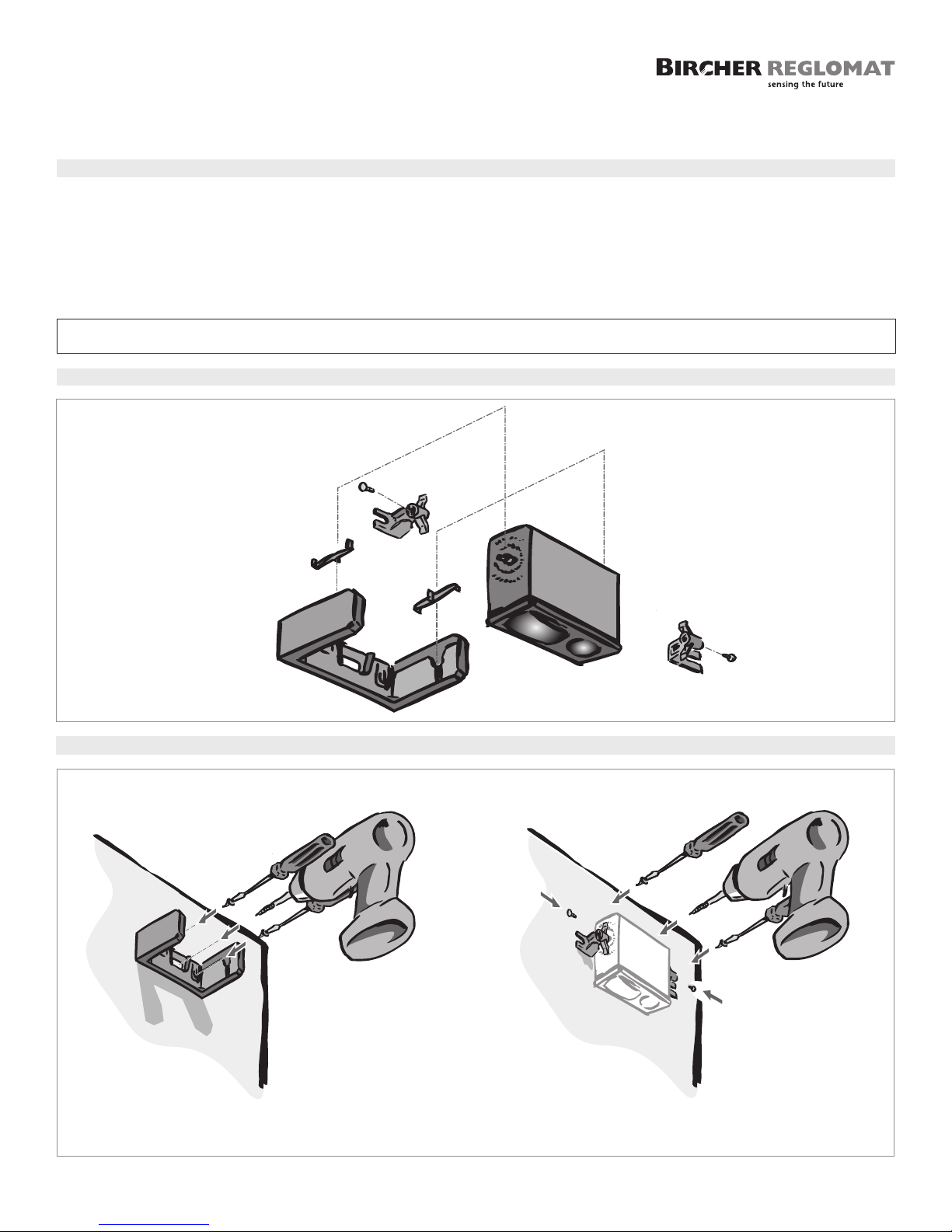
2. Disassembling the sensor
3. Mounting the sensor
Mounting with swivel bracket
1 Screw swivel bracket on surface
2 Use a drill to make an opening for the cable
Mounting with fixed brackets
1 Screw mounting brackets onto device
2 Mount device
3 Use a drill to make an opening for the cable
1
Page 2
5 4 3 2 1 5 4 3 2 1
~
86”
~51”
~86"
(2.2 m)
~51"
(1.3 m)
+
–
5 4 3 2 1 5 4 3 2 1
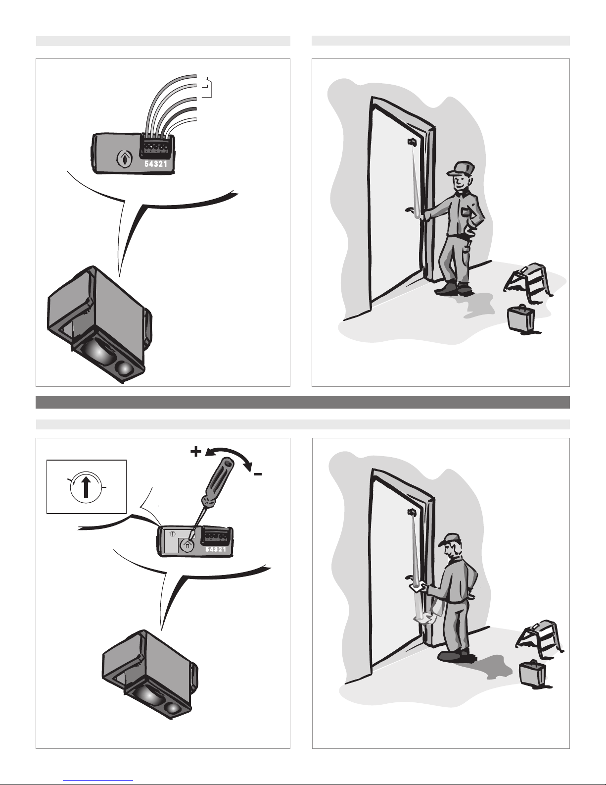
5 NC
4 NO
3 Common
2 + ~ 18-28 V AC
1 – ~ 12-30 V DC
4. Wiring the MicroScan
5. Testing factory setting
Switch on after mounting and exit detection area for 10 seconds.
Special settings
6. Setting the scanning range
Check the detection area with a sheet of paper or hand.
Set the exact range by turning scanning range setting screw
2
with a screw driver.
Check the new scanning range with a sheet of paper or hand.
Page 3
51 inch
(1.3 m)
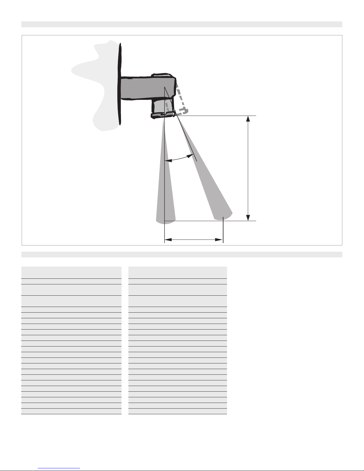
+1 Click =
~ 8 inch
(~ 0.2 m)
9°
7. Setting the detection area
8. Technical specifications
Scanning area
on white Kodak paper
Scanning range area
Light spot diameter
with scanning range 51” (1300 mm)
B/W difference
with scanning range 51” (1300 mm)
Response time
Relay holding time
Operating voltage
Current consumption
Signal output
MicroScan
relay 1x floating changeover contact
maximum switching voltage
maximum switching current
maximum switching power
Function indication
Connection type
Protection class
Housing material
Lens surface
Operating temperature
Weight
Electromagnetic compatibility
7.87” (0.2m) - 86.62” (2.2m)
approximately 47.24” (1.2m) - 86.61” (2.2m)
approximately 2” (60mm)
approximately 51” (1300 mm)
approximately 16” (400mm)
approximately 51” (1300 mm)
approximately 50 ms
approximately 250 ms
18 - 28 V AC / 12 - 30 V DC
<50 mA
active on detection
48 V AC / DC
0.5A AC / 1A DC
VA / 24 W
55
LED red lights up when output is active
plug-in screw terminal, cable 16.4’ (5m) supplied
IP 52
ABS
PMMA
-4°F (-20°C) - 140°F (60°C)
approximately 1.76 ounces (50 g) without cable
EMC directive 89/336EEC
Detection area inclination
3
Page 4
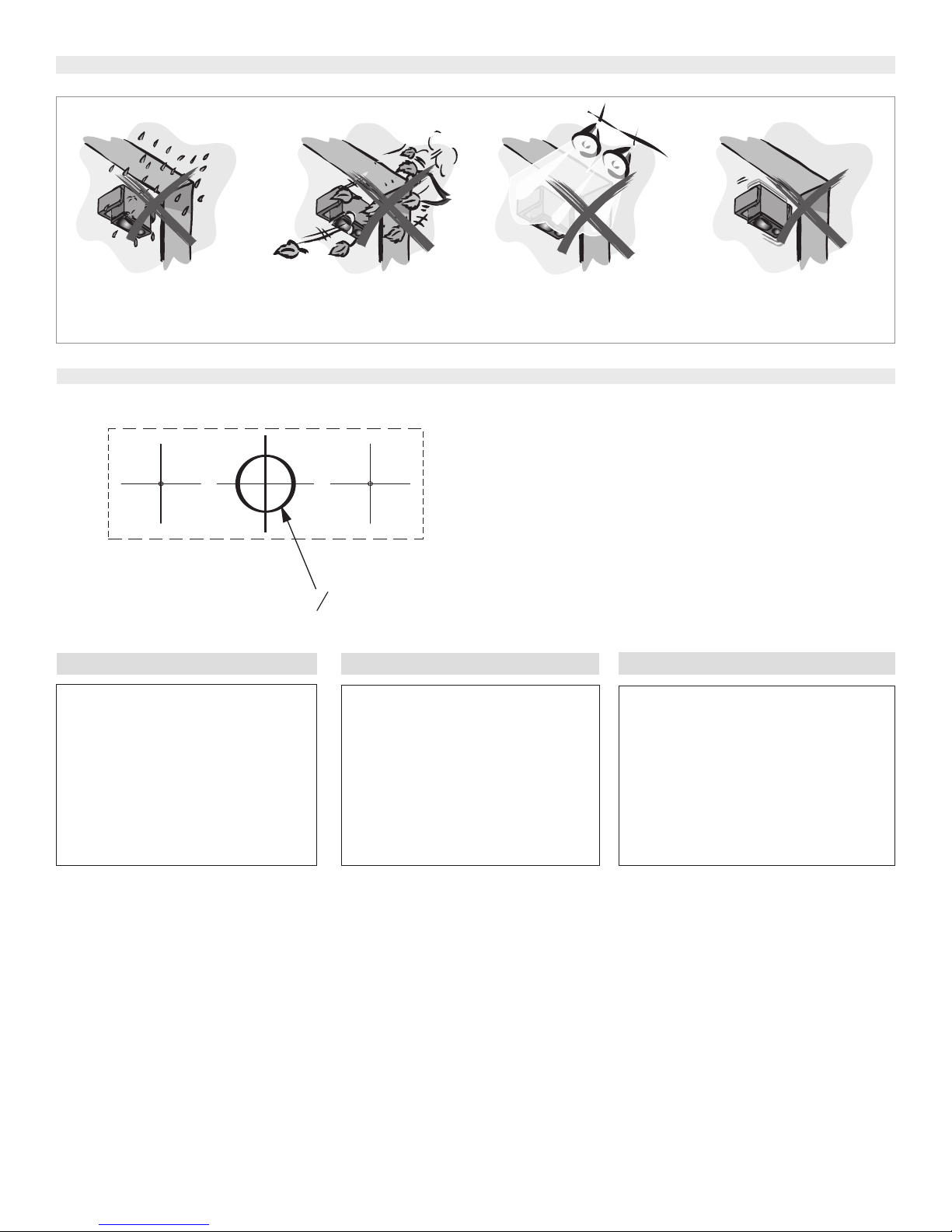
9. Avoid interferences
approx. 1/
2
"
(13mm)
O
The device should be mounted so it is
protected from rain
10. Drilling template for swivel bracket
✄✄
11. Contact
If after troubleshooting a problem, a
satisfactory solution cannot be achieved,
please call:
Bircher Reglomat at 800- 252-1272
from 8am - 5pm central standard time.
You may also visit our website at:
.bircherreglomat.com
www
DO NOT LEA
NEVER SACRIFICE SAFETY FOR ANY REASON
VE ANY PROBLEMS UNRESOLVED
The device shouldn’t be mounted around
objects in motion (for example: fans,
plants, trees, flags etc.)
12. Disclaimer
Bircher Reglomat reserves the right to change
any information on this document without
notice.
For the latest version, please log on to
www.bircherreglomat.com
or call us at 847-952-3730 to request a copy of
the current version.
Do not mount the device near halogen
lighting
13. FCC Approval
- This Class B digital apparatus complies with
Canadian ICES-003. Cet appareil numérique de la
classe B est conforme à la norme NMB-003 du
Canada.
- This device complies with part 15 of the FCC
Rules. Operation is subject to the following
two conditions:
1. This device may not cause harmful interference,
2. This device must accept any interference
received, including interference that may
cause an unwanted operation.
Mount the device on a solid surface
4
K6203.035 11/05
 Loading...