

Page 1

®Copyright 2015 July All Rights Reserved Version 1.0
The information contained in this document is subject to change without notice. We make no warranty of any
kind with regard to this material, including, but not limited to, the implied warranties of merchantability
and fitness for a particular purpose. We shall not be liable for errors contained herein or for incidental
or consequential damages in connection with the furnishing, performance, or use of this material.
This document contains proprietary information that is protected by copy right. All rights are reserved. No part of
this document may be photocopied, reproduced or translated to another language without the prior
written consent of the manufacturer.
TRADEMARK
Intel®, Pentium® and MMX are registered trademarks of Intel® Corporation. Microsoft® and Windows® are
registered trademarks of Microsoft Corporation.
Always high- speed! absolutely desirable
Page 2
Main Board
CPU
PP-8100-15 Intel® Bay trail Celeron J1900 Processor D/M Series (2M Cache, 2.0 GHz)
Chipset
Intel® SoC
System Memory
Max 2 DDR3L 1333 MHz SO-DIMM slots, up to 8GB
Graphic Memory
Intel® HD Graphics
LCD Panel
PP-8100-15
Panel Size 15”
Maximum Resolution 1024 x 768
Brightness 250 cd/m1
Contrast Ratio 700 : 1
Response Time 16 ms
View Angles (H/V) 150 / 120
Touch Panel Five Wires Resistive Touch or Projected Capacitive Touch
Storage
HDD
2.5” SATAIII interface x 1
Expansion
Socket One Mini-PCIE or One Msata II
Power
Power Adaptor Input AC 100-240V 2.5A 50/60Hz, Output DC 12V 6.66A
I / O
USB Six USB 2.0
Serial Three COM ports with DB-9 Connector
COM1 with 5V / 12V power selectable
LAN Max 2 Realtek 8111G Gigabit Fast Ethernet controllers
2nd VGA Output One 15 Pin VGA Port
PS/2 One
Audio Two Earphone & Two Microphone
1
1
Page 3

Control/Indicator
Power Button One
LED Indicators Power (Red)
Optional Peripherals
Magnetic Card Reader ISO Track 1/2/3, USB interface
VFD customer display 20 x 2 characters, RS-232 interface
Dimensions
PP-8100-15 358(W) X 70(L) X 293(H) mm
PP-8100-T15 358(W) X 223.9(L) X 309.6(H) mm
Environment
Operating Temperature 0°C ~ 40°C ( 32°F ~ 104°F )
Storage Temperature - 20°C ~ 60°C ( - 4°F ~ 140°F )
Operating Humidity 10% - 80% RH non condensing
Storage Humidity 10% - 80% RH non condensing
Model Number
PP-8100 - X–SS Intel® Bay trail Celeron J1900 Processor D/M Series (2M Cache, 2.0 GHz)
X : T --- Contain foot
SS : 15 --- 15" TFT LCD
2
Page 4
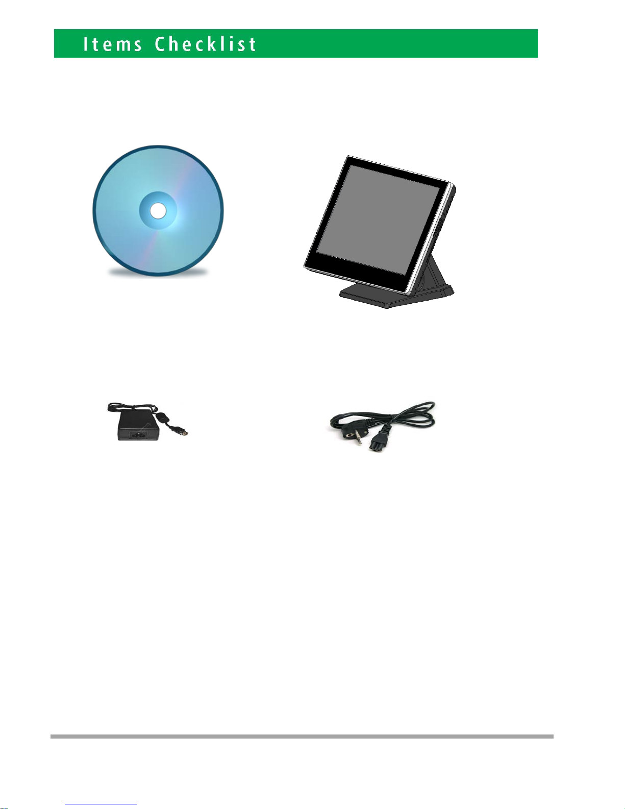
If any item is missin g, pl ease con t act your sale agent i mmediat el y.
Take the system unit out from the carton. Remove the unit by carefully holding the foam inserts and remove slowly to protect
the system. The following items should be found in the carton:
1. CD that including all
driver and manual
2. The System
. Power Adaptor 4. AC Power Cord
2
3
Page 5
Please un plug th e A C power of the adapter before opening an y part of the system. Sin ce t he
standby power is always on after the adapter is plugged in. It may cause permanen t damage to
your system when you open any part of i t .
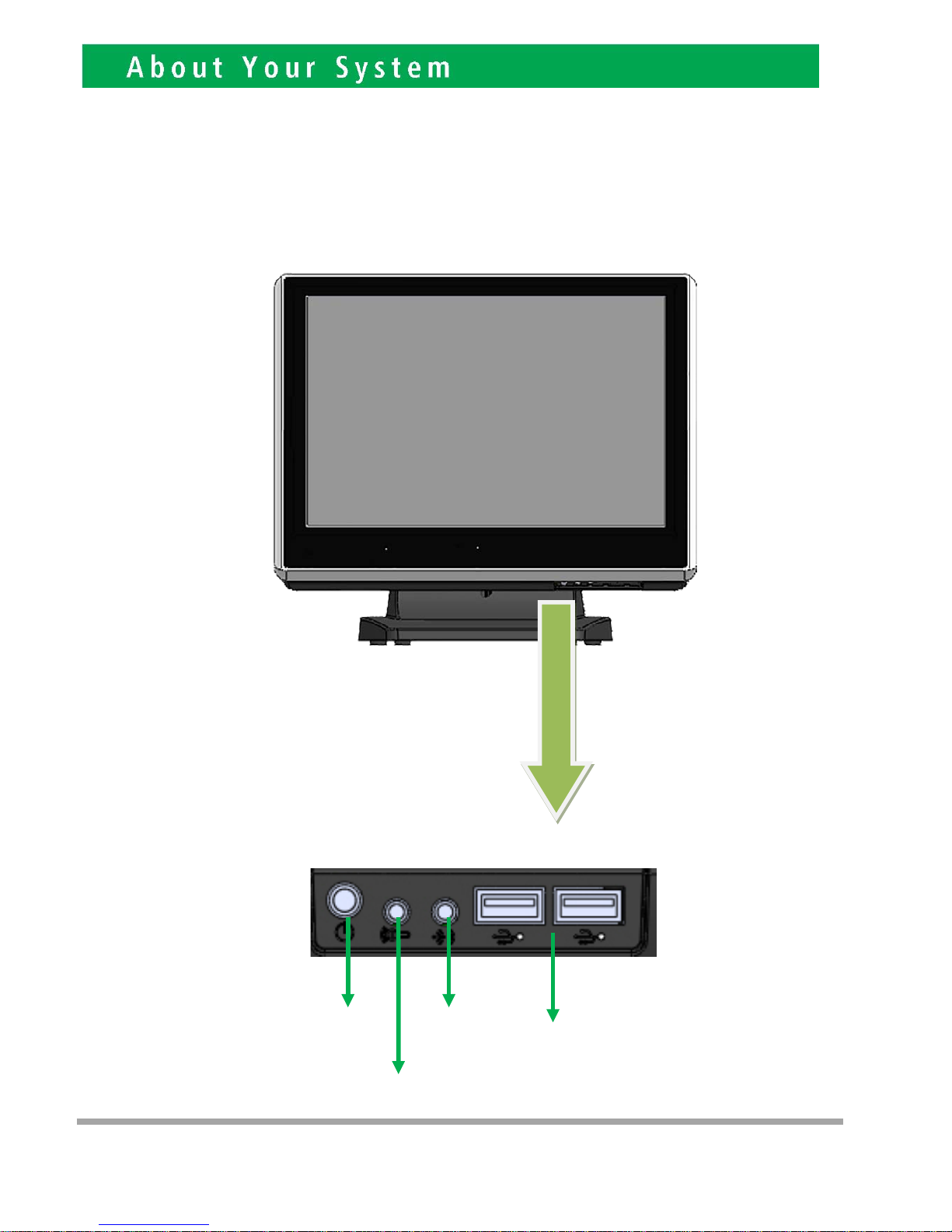
Front View
3
Power
Button
Microphone
Earphone
USB 2.0
4
Page 6
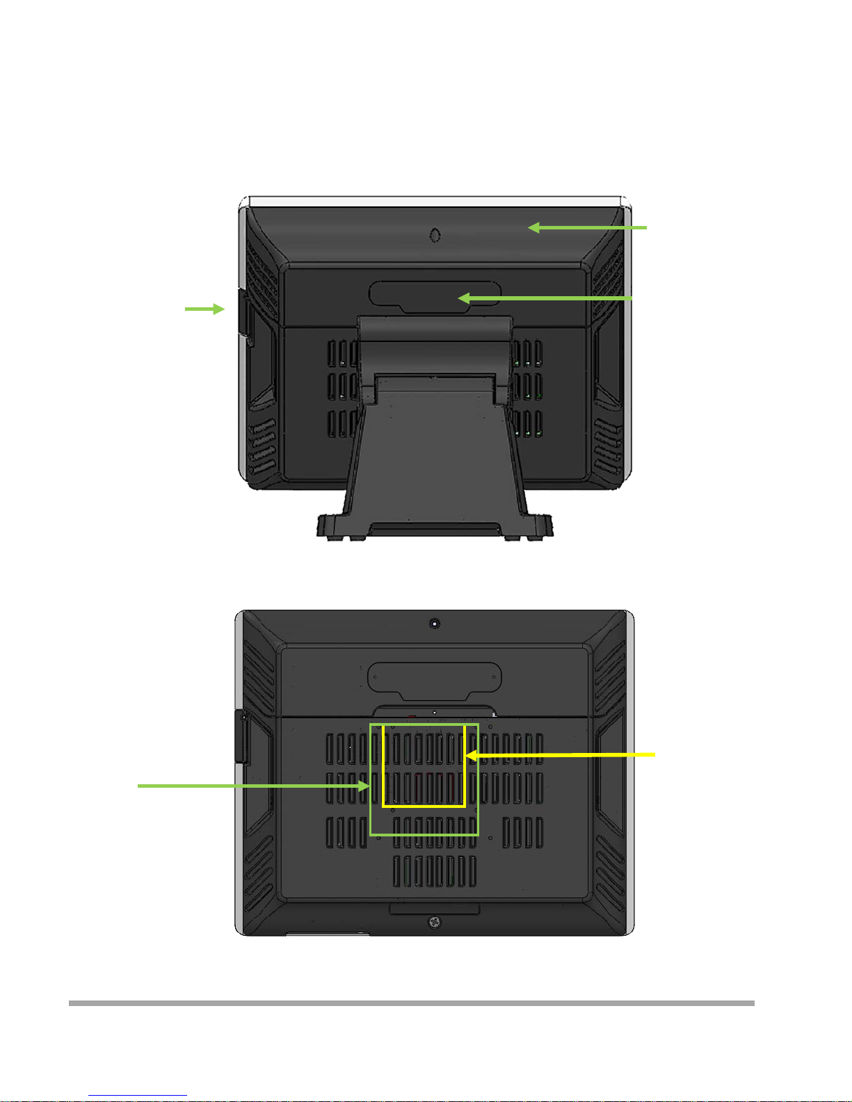
Rear View
Slot for installing
Magnetic Card
Rea der (op t ional)
Cable Cover
Slot for installing
Custo m Display
or Second Display
(optional)
VESA 75
VESA 100
5
Page 7
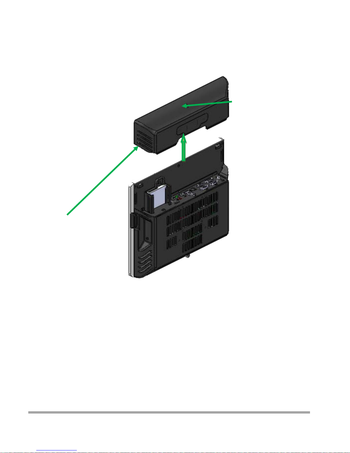
How to open the connector bezel
Please un plug th e A C power of the adapter before opening an y part of the system.
Since the standby power is always on after the adapter is pl ugged in.
It may cause permanent damage to your system w hen you open any part of it.
As illustrated in
the follow i ng,
Move the se two sides upw ard
Release the screw
6
Page 8
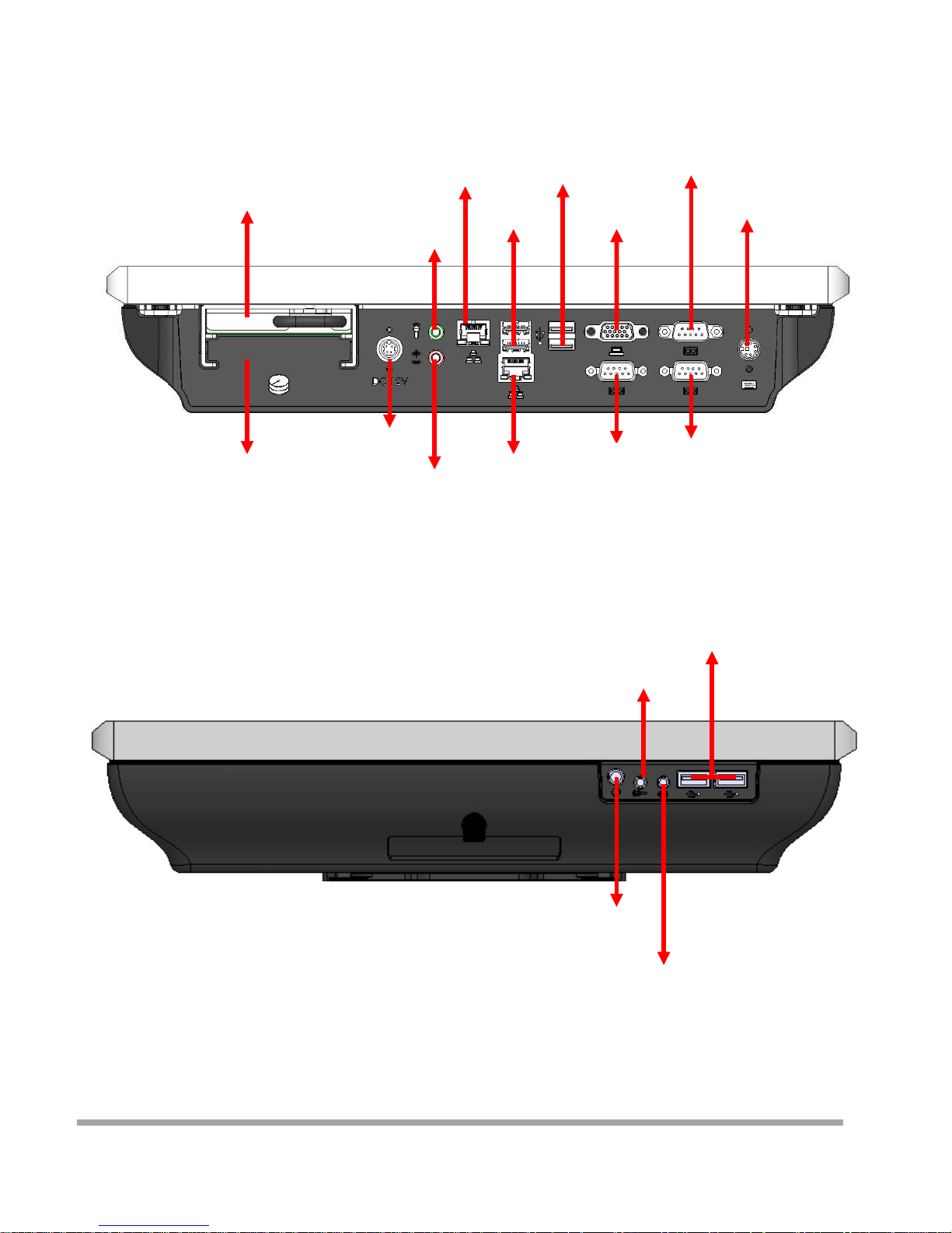
The connector panel
1. TOP of machine
2. Bottom of machine
Hard Disk 2
Power IN
Earphone
Microphone
LAN
USB 2.0
USB 2.0
VGA
COM1
LAN
COM3
COM2
P S /2
Power Button
Microphone
Earphone
USB 2.0
Hard Disk 1
7
Page 9
Please un plug th e A C power of the adapter before opening an y part of the system. Sin ce t he
standby power is always on after the adapter is plugged in. It may cause permanen t damage to
your system wh en you open any part of the system.
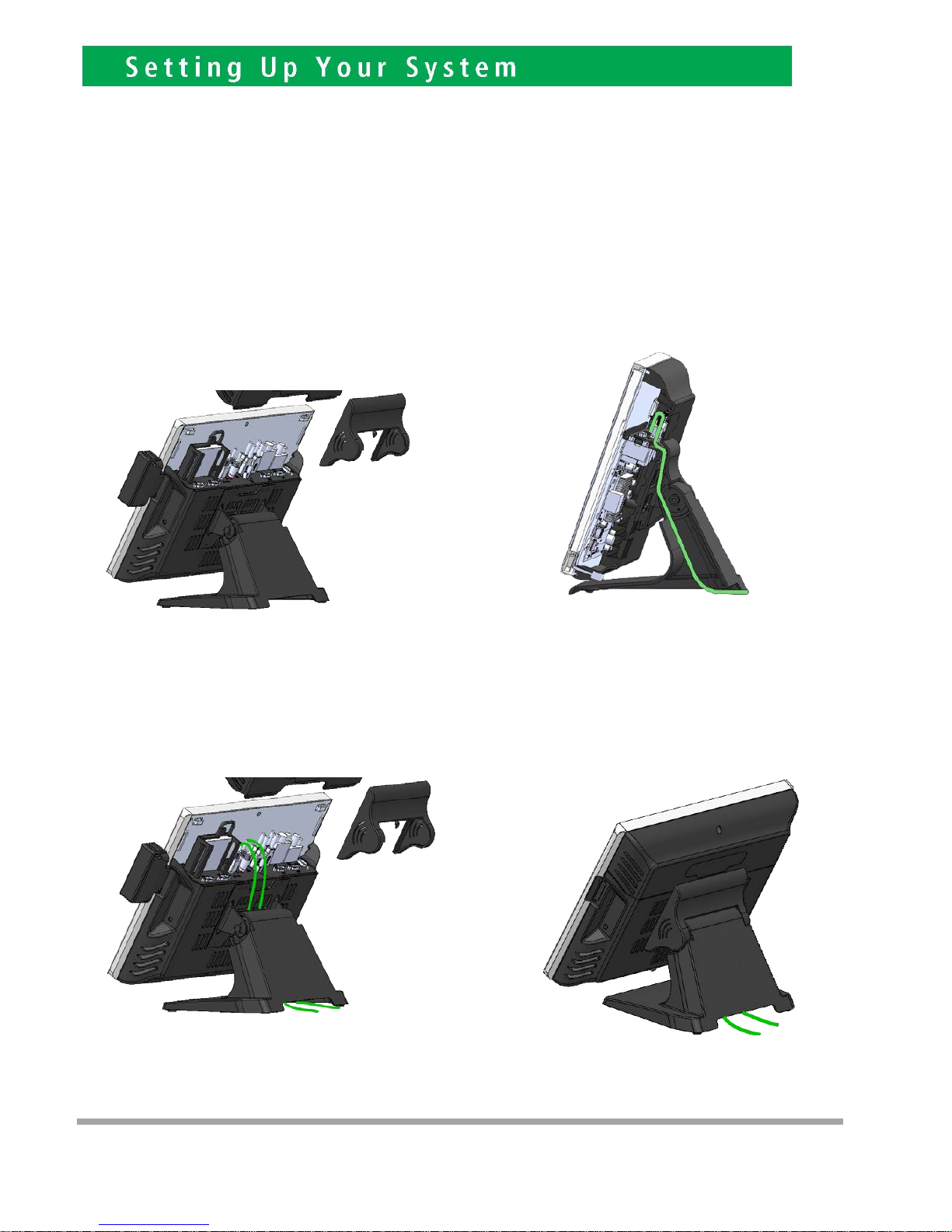
Installing Peripherals
To install the peripheral’s cables, please follow the method described below.
It will make the process much easier
.
1. Open the Cable cover and Hinge cover 2. Follow the way of drawing to wiring
Plug in all the cable on the hots
3. Through the cable between HOST and FOOT
4
8
Page 10
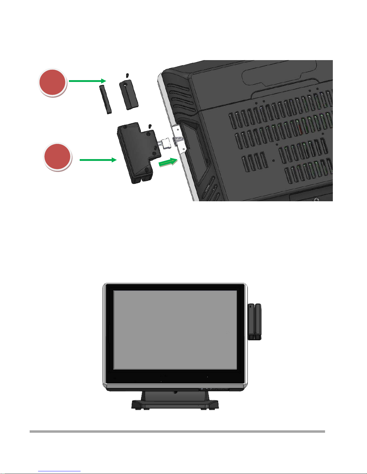
Installing Magnetic Card Reader (MSR)
1. Remove the rubber mat,Loosen the screw,and remove the MSR cover
2. Connected to the cable on the MSR and host,and lock two screws
1
2
9
Page 11
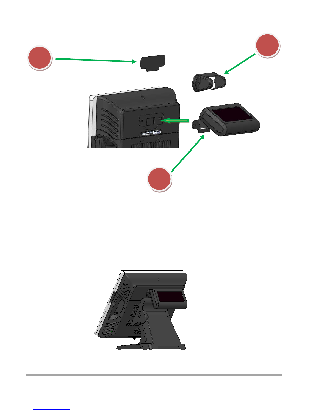
Installing Customer Display
1
2
3
1. Remove the metal bezel
2. Connected to the cable, lock the two screws on Cable Cover
3. Installation VFD cover and lock the two screws
10
Page 12
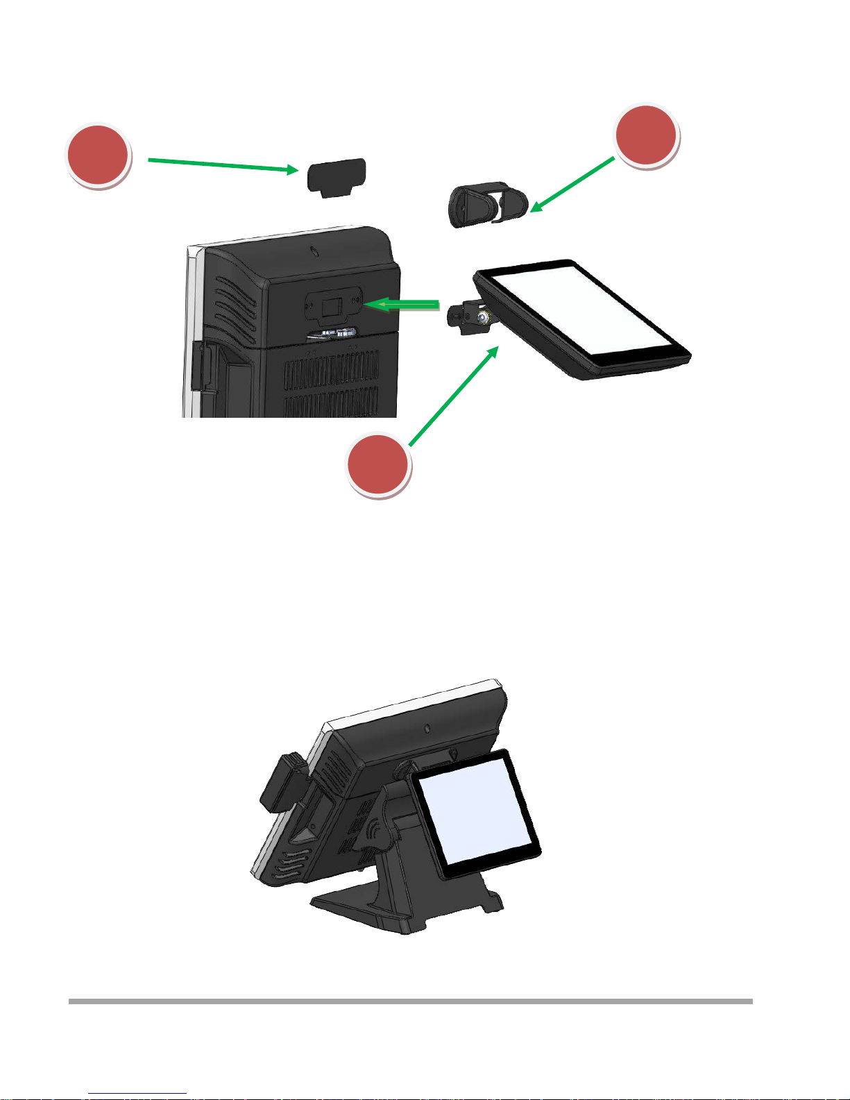
Installing Second Display
1. Remove the metal bezel
2. Connected to the cable, lock the two screws on Cable Cover
3. Installing the cover and lock the two screws
1
2
3
11
Page 13
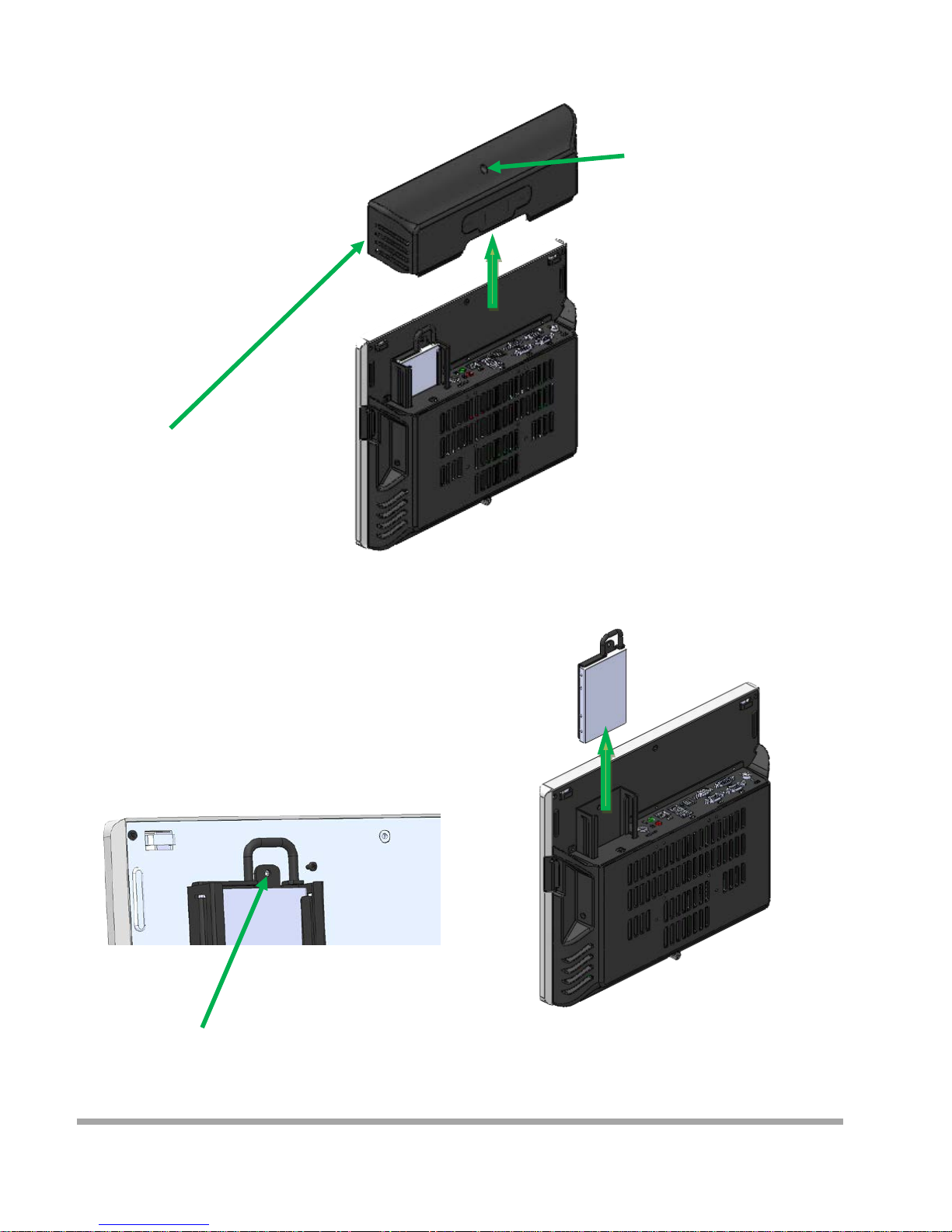
Remove and Installing Hard Disk
1. Release the screw
4. Grab the h andle and pull up or down
Remove or Installation Hard disk
2. Move these two side s upward
3. Release the screw
12
Page 14
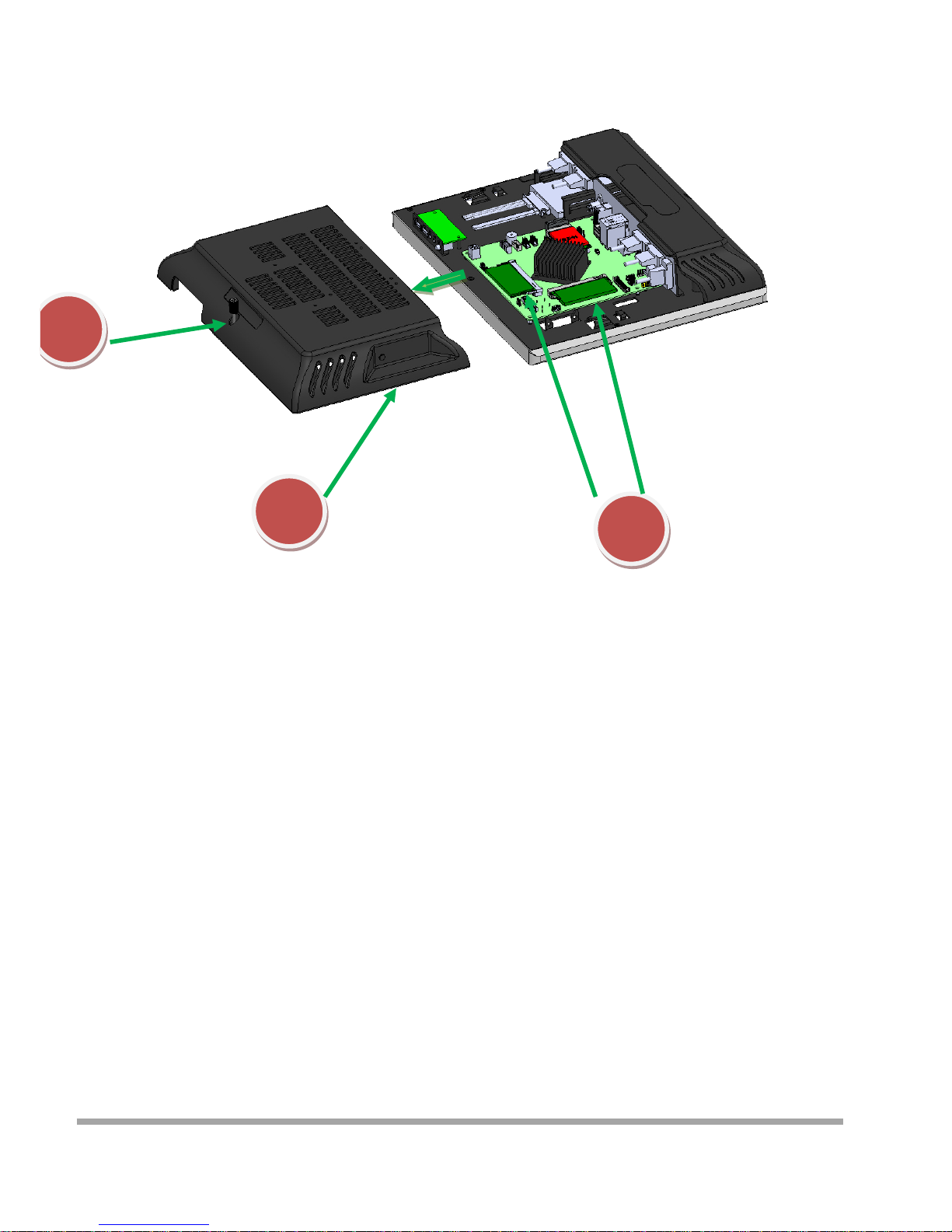
Remove and Installing Memory
1
2
1. Release the screw
2. Grasp the both sides , and pulled down the back cover
3. Replace or Installing Memory
3
13
Page 15
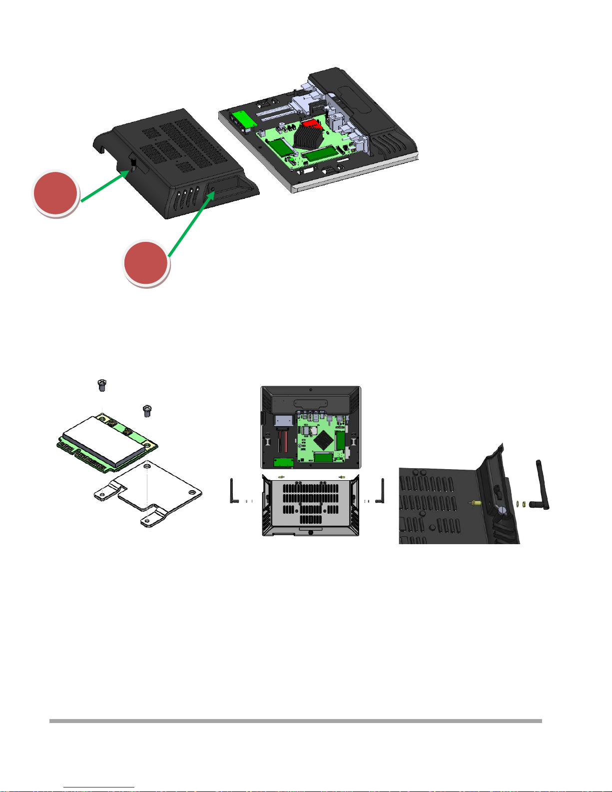
Installing WIFI Card and Antenna
1
2
1. Release the screw
2. Grasp the both sides , and pulled down the back cover
3. Install WIFI Card
Lock 2 screws
4. Remove the plastic pad on the both sides
of the Main cover
5. Inst all Antenna
14
Page 16
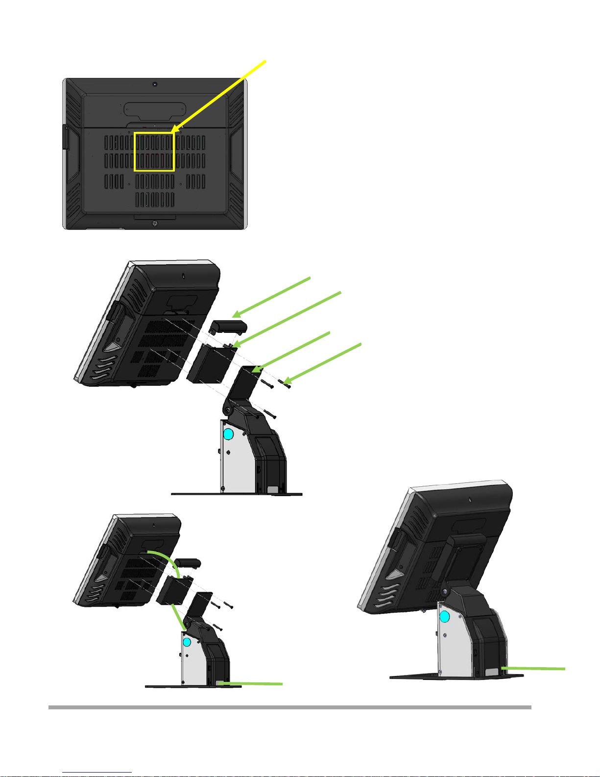
Installing A8V Printer
Lock the cable box and A8 on the
screw holes of the VESA75
Cover
Cable box
A8V
4 Screws
1. Put the Cable box on the back of CZAR
2. Put the A8V on the Cable box
3. Determine screw holes are aligned
4. Lock four screws
5. Install the Cover
How to install cable
15
Page 17
This chapter provides information on the BIOS Setup program and allows users to configure the system
for optimal use.
Users may need to run the Setup program when:
▄ An error message appears on the screen at system sta rtup and requests users to run SETUP.
▄ Users want to change the default settings for customized features.
Important
■ Please note that BIOS update assumes technician-level experienc e.
■ As the system BIOS is under continuous update for better system performance,
the illustrations in this chapter should be held for reference only.
5
16
Page 18

Entering Setup
Power on the computer and the system will star t POST (Pow er On Self Test) proces s. When the
message below appears on the screen, pre ss <DEL> o r <F2> ke y to e nte r Setup.
Press <DEL> or <F2> to enter SETUP
If the message disappears before you respond and you still wish to enter Setup, restart the system by
turning it OFF and On or pressing the RESET button. You may also restart the system by simultaneously
pressing <Ctrl>, <Alt>, and <Delete> keys.
Important
The items under each BI O S catego r y desc r ibed in this chapter are under continuous update for better
system performance. Therefore, the description may be slightly different from the latest BIOS
and should be held for reference only.
17
Page 19
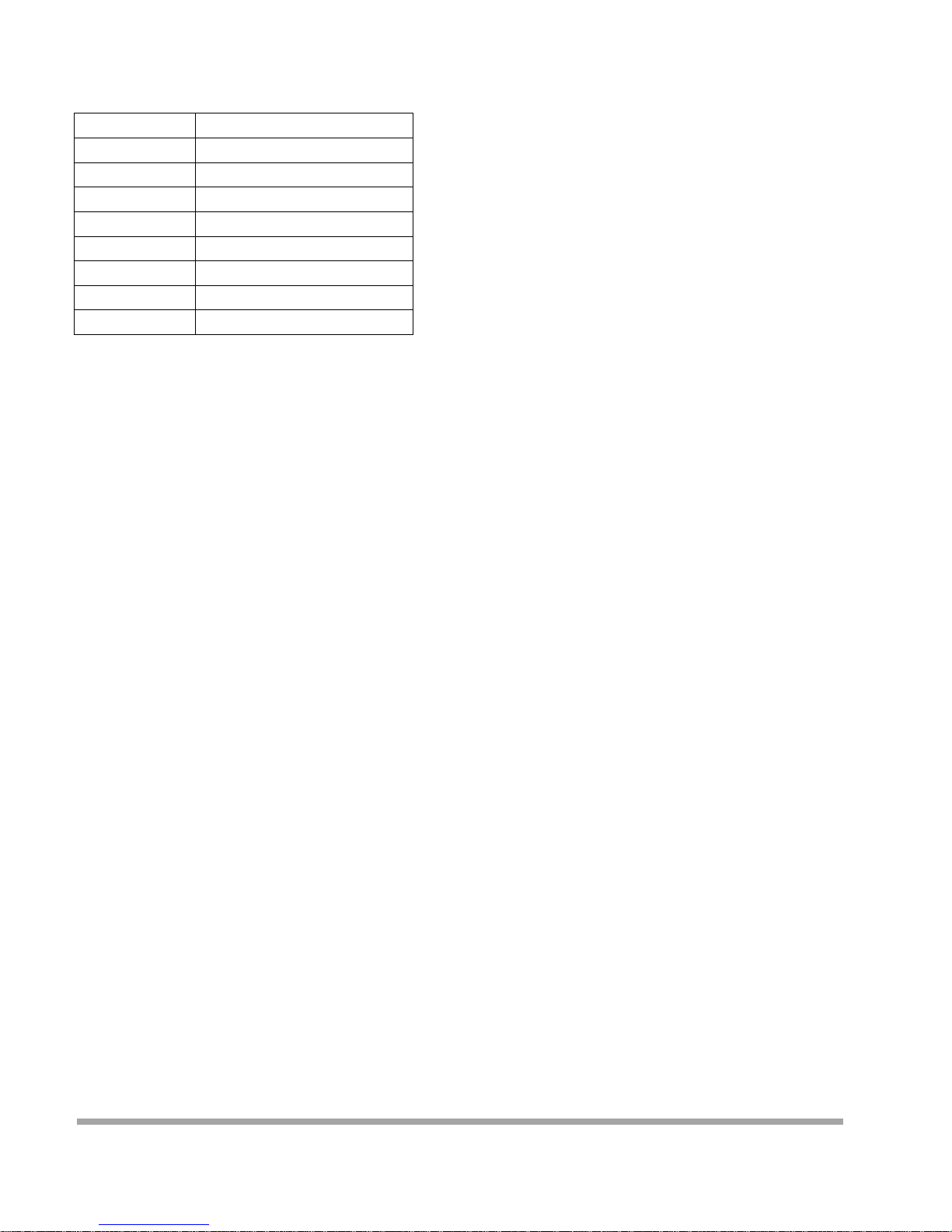
Control Keys
← →
Select Screen
↑ ↓
Select Item
Enter
Select
+ -
Change Option
F1
General Help
F7
Previous Values
F9
Optimized Defaults
F10
Save & E xit
Esc
Exit
Getting Help
After entering the Setup menu, the first menu you wi ll see is the Main Menu.
Main Menu
The main menu lists the setup functions you can make changes to. You can use the arrow keys ( ↑↓ ) to
select the item. The on-line description of the highlighted setup function is displayed at the bottom of the
screen.
Sub-Menu
If you find a right pointe r symbol appears to the left of certain fields that mea ns a sub -me nu can be
launched from this field. A sub-me nu contains addi tio nal options fo r a field parame te r. You can use arrow
keys ( ↑↓ ) to highlight the field and press <Enter> to call up the sub-menu. Then you can use
the c ontr ol keys t o enter values and move f r om field to fi eld with i n a sub-menu. If you want to return to
the main me nu, just pres s t he <Esc >.
General Help <F1>
The BIOS setup program provides a General Help screen. You can call up this screen from any menu by
simply pre s sing <F1>. The Help screen lists the approp r iate key s to use and the po ssibl e sele c tions for
the highlighted item. Press <Esc> to exit the Help scre en.
18
Page 20
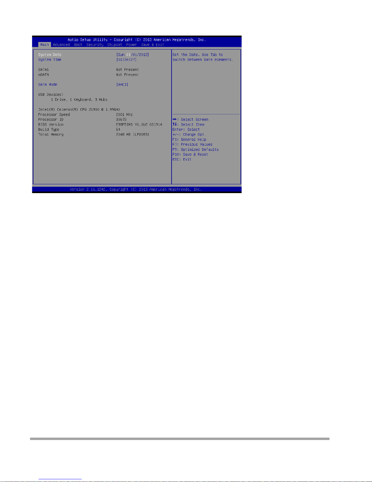
The Menu Bar
▶
Main
Use this menu fo r ba sic system configurations, suc h as time, date, etc.
▶
Advanced
Use this menu to set up the items of special enhanced features.
▶
Boot
Use this menu to specify the priority of bo ot devices.
▶
Security
Use this menu to set supervisor and user passwords.
▶
Chipset
This menu controls the advanced features of the onboard chipsets.
▶
Power
Use this menu to specify your settings for power managem ent.
▶
Save & Exit
This menu allows you to load the BIOS default values or factory default settings into the BIOS and exit
the BIOS setup utility with or without changes.
19
Page 21
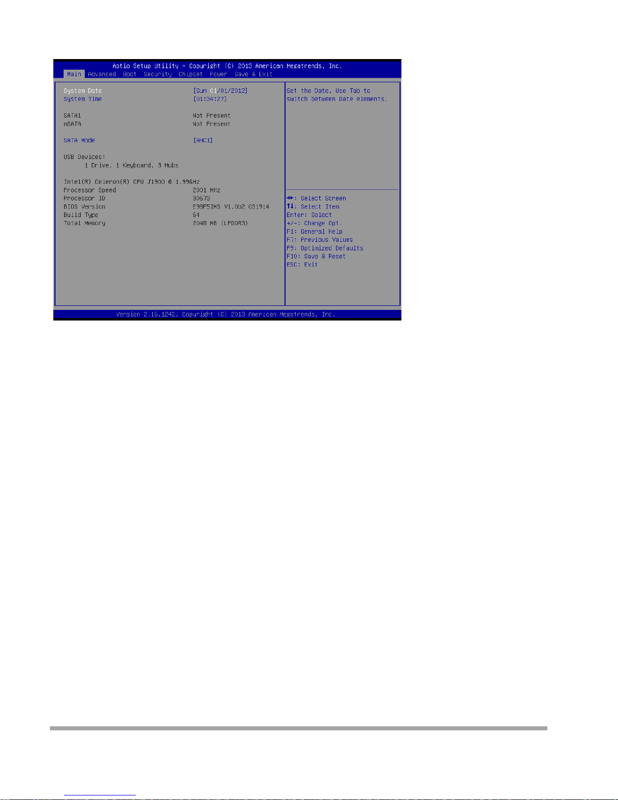
Main
▶
Syste m Date
This setting allows you to set the system date. The date format is <Day>, <Mo nt h> <Date> <Year>.
▶
Syste m Time
This setting allows you to set the system time. The time format is <Hour> <Minute> <Second>.
▶
SATA Mode
This setting specifies the SATA controller mode.
20
Page 22
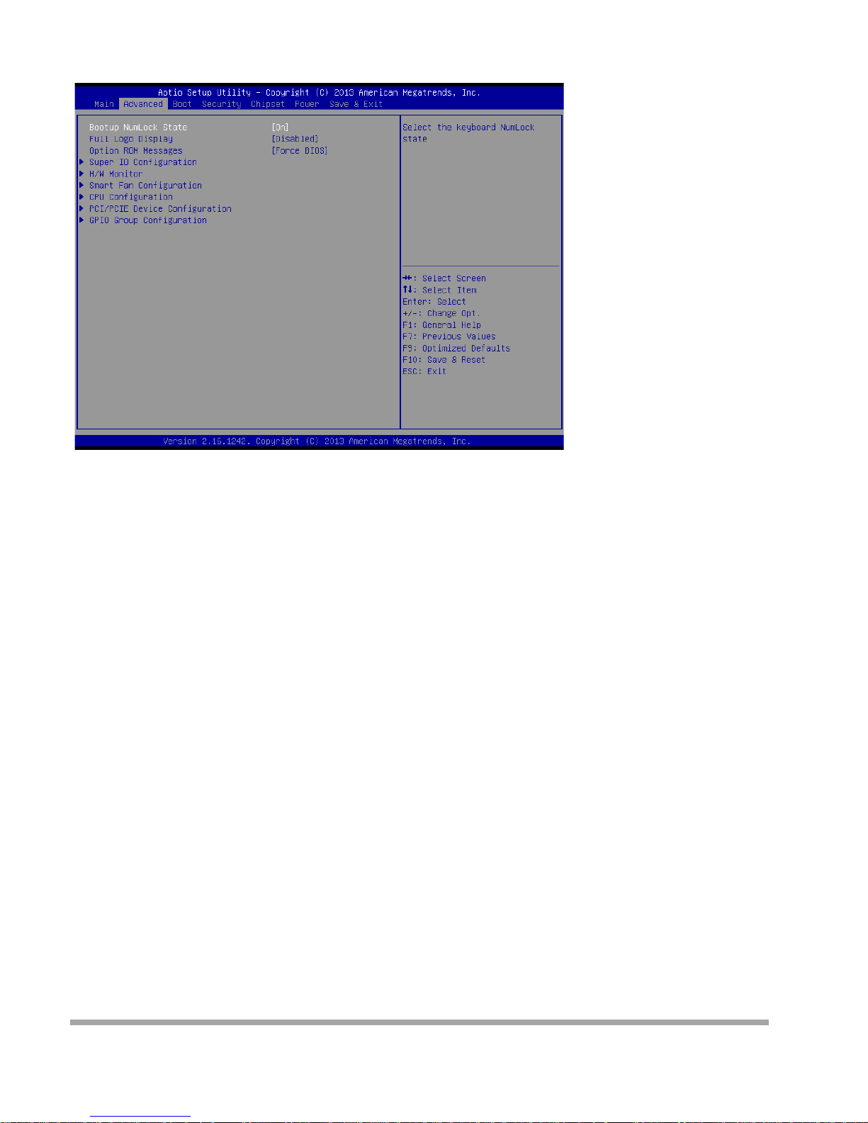
Advanced
▶
Bootu p NumLock Stat e
This setting is to set t he Num Lo ck status when the system is powered on. Setting to [ O n] will turn on the
Num Lock key when the system is powered on. Setting to [Off] will allow users to use the arrow keys on
the numeric keypad.
▶
Full Logo Di s pl ay
This BIOS feature determines if the BIOS should hide the normal POST messages with the
motherboa rd or system manufacturer’s full -screen logo.
When it i s enabl ed, the BIOS wil l displa y t he full-screen logo dur ing the boot-up sequence, hidi ng normal
POST messages.
Whe n it is disabled, the BIOS will display the normal POST messages, instead of the full-screen logo.
Please note that enabling this BIOS feature often adds 2-3 seconds of delay to the booting sequence.
This dela y ens ure s that the logo is di spla yed for a sufficie nt amo unt of time. There fo re, it is
recommended that you disable this BIOS feature for a faster boot-up time.
▶
Option ROM Messages
This item is used to determine the display mode when an optional ROM is initialized during POST. When
set to [Force BIOS], the display mode used by AMI BIOS is used. Select [Keep Current] if you want to
use the display mode of o pt ional RO M.
21
Page 23
▶
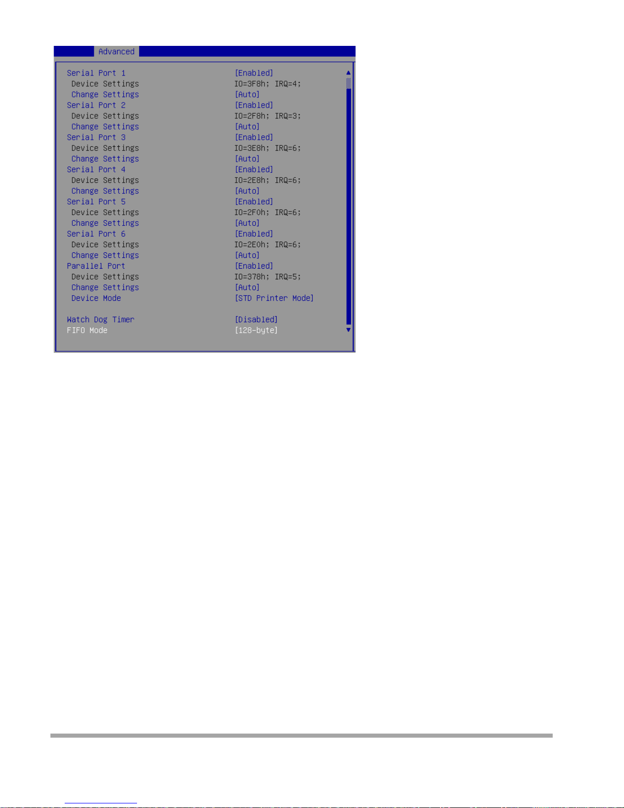
Super IO Configuration
▶
Serial Port 1/ 2/ 3/ 4/ 5/ 6
This setting enables/disables the specified serial port.
▶
Change Settings
This setting is used to change the address & IRQ settings of the specified serial port.
▶
Parallel Port
Th is setting ena bles/disab les the parallel por t.
▶
Change Settings
This setting is used to change the address & IRQ settings of the parallel port.
▶
Device Mode
Select an operation mode for the parallel port.
▶
Watch Dog Timer
You can enable the system watch-do g t imer, a hardware ti mer that genera tes a reset when the softwa r e
that it mon i tors does not respond as expecte d each time the w at c h dog p olls it.
▶
FIFO Mode
This setting controls the FIFO data transfer mode.
22
Page 24
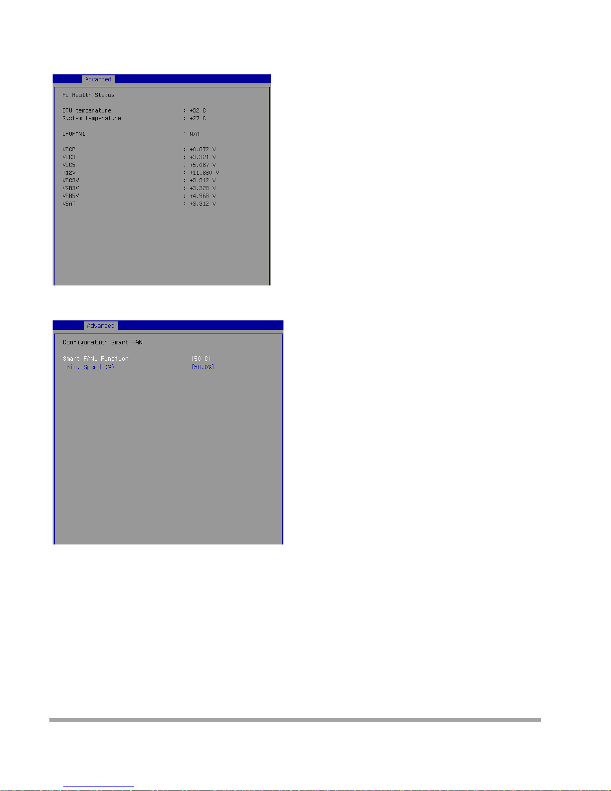
▶
H/W Mon itor
Th es e i tems di splay t he current status of all monitored hardware de vices / c omponents su c h as vol tages ,
temperatur es and all fans’ speeds.
▶
Smart Fan Confi guration
▶
Smart FAN1 Function
These setting s enable/disable the Smart Fan functio n. Smart Fan is an excel-lent f eat u re whic h will
adjust the CPU/syst em fan speed automati call y de -pending on the current CPU/system temperature,
avoiding the overheating to damage your system.
▶
Min. Speed (%)
This setting selects the minim um percentag e of 12V that the fan needs to start spinning.
23
Page 25
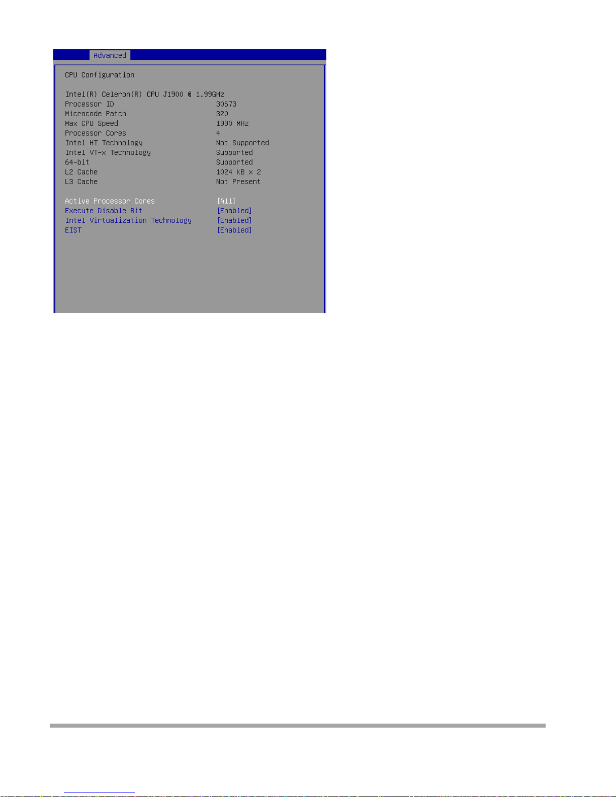
▶
CPU Configu rati on
▶
Act ive Processor Cores
This setting specifies the number of active processor cores.
▶
Execut e Disabl e Bit
Intel’s Exe c ute Disabl e Bi t fun ctionality can prev ent certain class es of mal i c ious “buffer overflow” attacks
when combined with a supporting operating system. This functionality allows the pro cessor to cla ssify
areas in memory by where application c ode can execute and where it cann ot . When a malicious worm
attempts to insert code in the buffer, the processor disables code execution, preventing damage or worm
propagation.
▶
Intel Virtualization Technology
Virtualization enhanced by Intel Virtualization Technology will allow a platform to run multiple operating
system s and appli cati ons in independent partitio ns. With vi rtualization, o ne comp uter sy stem can
function as multiple “Virtual” systems.
▶
EIST
EIST (Enhance d I ntel SpeedStep Technolog y) allow s t he system to dynamically adjust processor
voltage a nd co re frequenc y, which can result in de-creased a ve rage power consum pt ion
and d ecreas ed average heat pro du ction. Wh en disable d, the pr ocessor will return the ac t ual maximum
CPUID inpu t value of the pr ocessor when queried.
24
Page 26
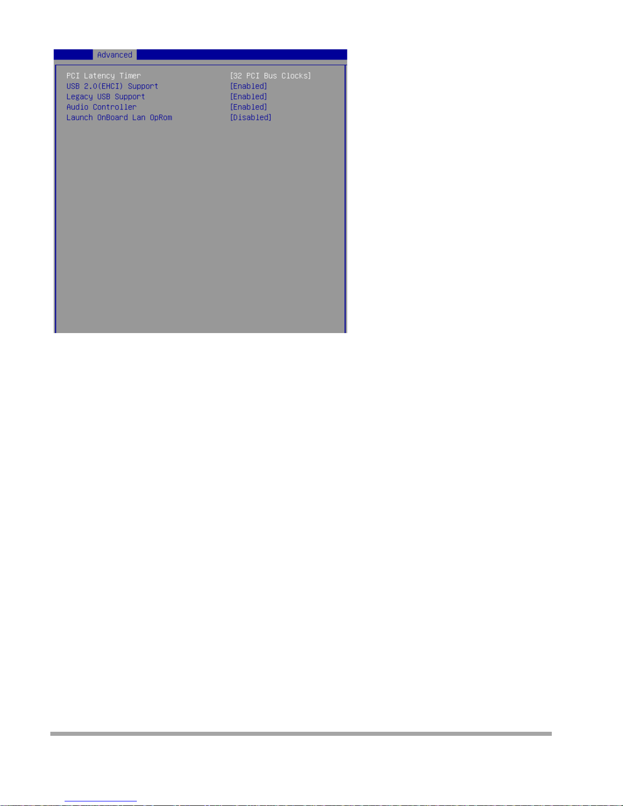
▶
PCI/PCIE Device Configu ration
▶
PCI Laten cy Ti me r
This item controls how long each PCI device can hold the bus before another takes over. When set to
higher values, every PCI device can conduct trans-actions for a longer time and thus impro ve t he
effective PCI bandw idth. For better PCI per formanc e, you should set the item to higher value s.
▶
USB 2.0 ( EHCI) Support
This setting disables/enables the USB EHCI controller. The Enhanced Host Controller Interface (EHCI)
specification describes the register-level interface for a Host Controller for the Universal Serial Bus (USB)
Revision 2.0.
▶
Legac y USB Suppo rt
Set to [Enabled] if you need to use any USB 1.1/2.0 de vice in the operating system that does not support
or have any USB 1.1/2.0 driver installed, suc h as DOS and SCO Unix.
▶
Audio Cont rol l e r
This setting enables/disables the onboard audio controller.
▶
Laun ch OnBoa rd LAN OpROM
These settings enable/disable the initialization of the onboard/onchip LAN Boot ROM during bootup.
Selecting [ Di sabled] will speed up the bo ot process.
25
Page 27
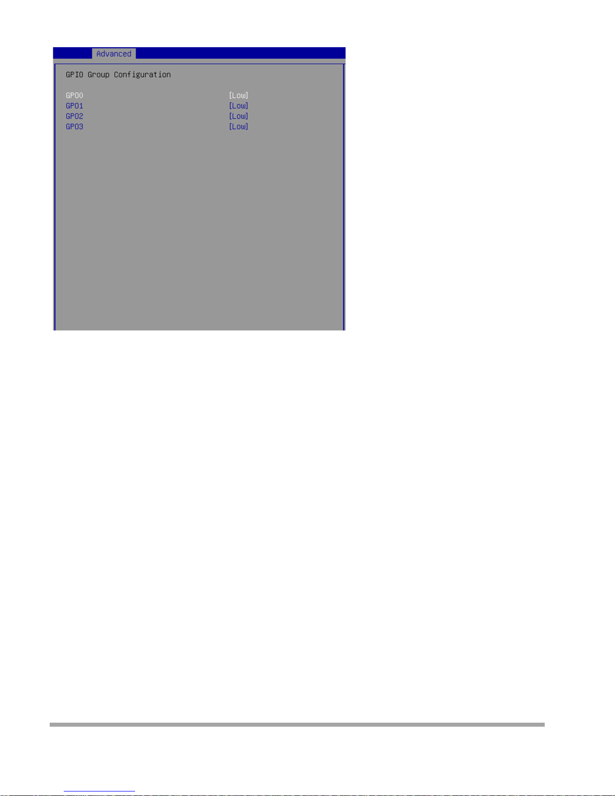
▶
GPIO Group Configuration
▶
GPO0 ~ GPO3
These settings control the operation mode of the specified GPIO.
26
Page 28
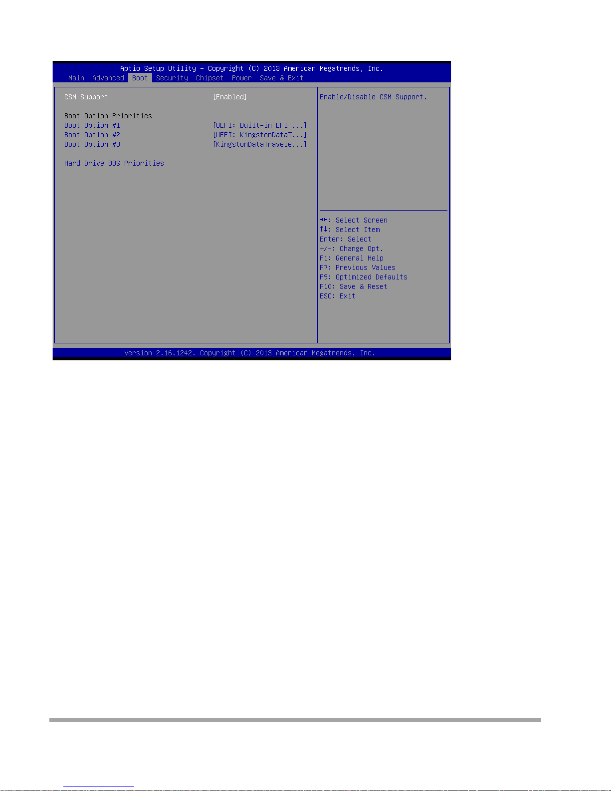
Boot
▶
CSM Support
This setting enables/disables the support for Compatibility Support Module, a part of the Intel Platform
Innovation Framework for EFI providi ng the capability to support lega cy BI O S inter fa ces .
Important
If the Operating Syst em is going to boot in UEFI mode, disable CSM Support to speed up the boot
process.
▶
Boot Option Priorities
This setting allows users to set the sequence of boo t de vices where BIOS at-tempts to load the disk
operating system.
▶
Hard Drive BBS Priorities
This setting allows users to set the priority of the specified devices. First press <Enter> to enter the
sub-menu. Then you ma y use the arrow k eys ( ↑↓ ) to select the desired device, then press <+>, <->
or <Page Up>, <PageDown> key to move it up/dow n in the priority list.
27
Page 29
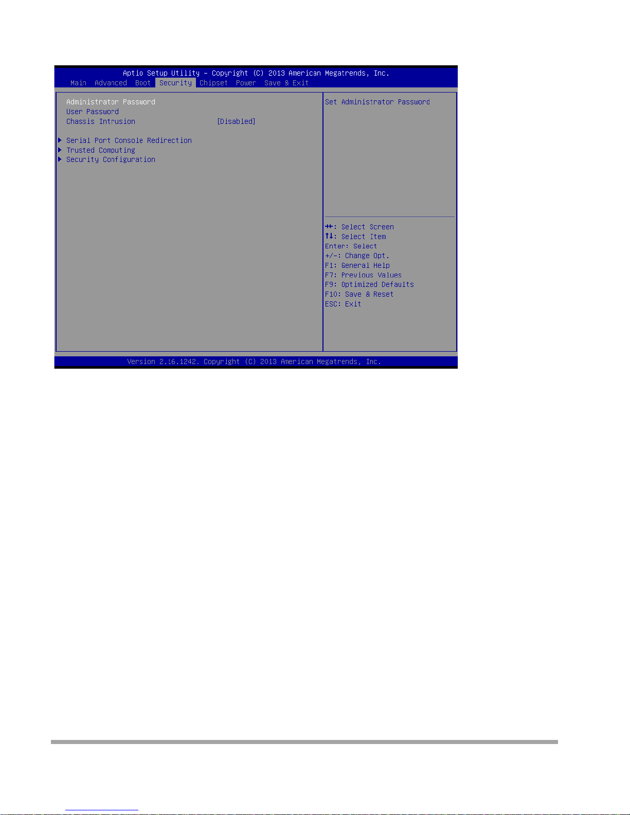
Security
▶
Admin i st rator Password
Adm inistrator Password controls access to the BIOS Setup utility.
▶
User Password
User Password controls access to the system at boot and to the BIOS Setup utility.
▶
Chassis Intru si on
Th e f ield en ables or disa bles the featur e of recording the chassis intrusi on status and i s suing a w arning
message if the chassis is once opened.
28
Page 30
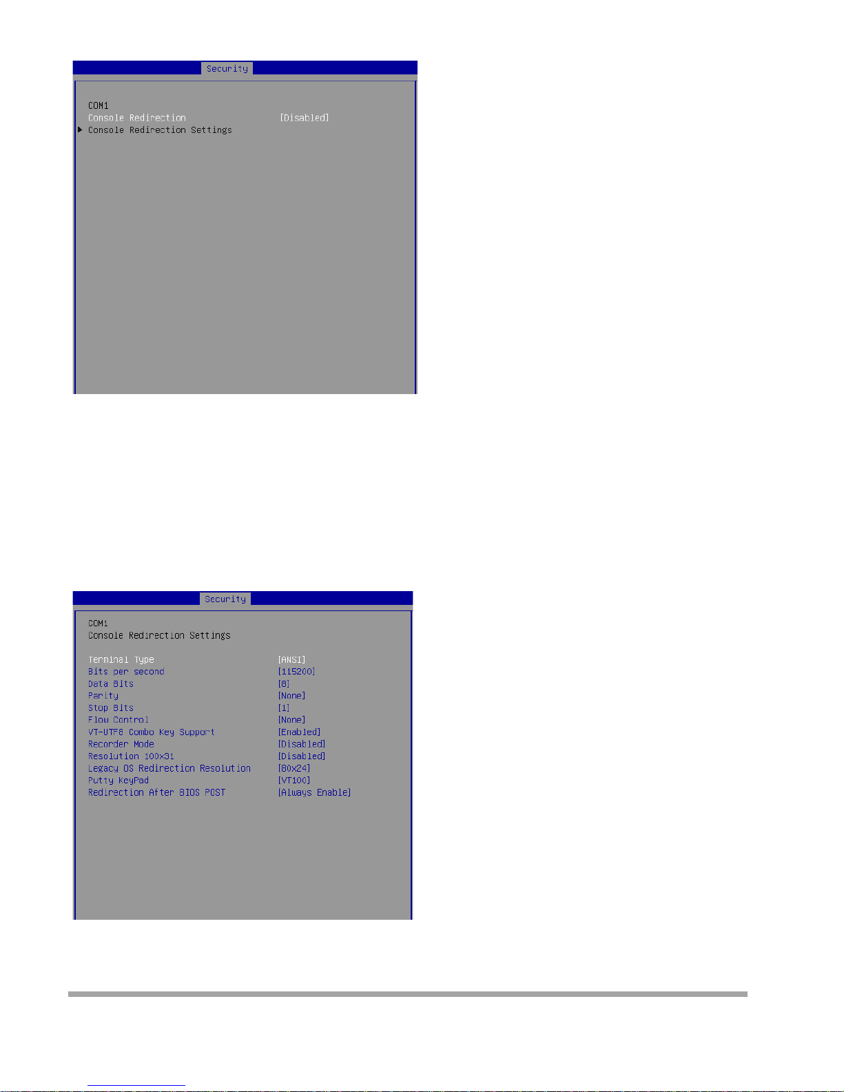
▶
Serial Port Con sol e Redirection
▶
Console Redirecti on
Console Redirection operates in host systems that do not have a monitor and keyboard attached. This
setting enables/disables the operation of console re-di re c tion. When set to [Enabl ed], BIOS redirects
and send s all content s that should be displa y ed on the screen to the serial COM port for displa y on the
terminal screen. Besides, all data received from the serial port is interpreted as keystrokes from a local
keyboard.
▶
Console Redirecti on Settings
29
Page 31

▶
Terminal Type
To operate t he system ’s console redirection, yo u need a terminal supp orti ng ANSI t erminal protocol
and a RS-232 null modem cable connected between the host system and terminal( s). Thi s setting
specifies the type of terminal device for console redirection.
▶
Bits per second, Data B i t s, Parity, Stop Bits
This setting specifies the transfer rate (bits per second, data bits, parity, stop bits) of Console
Redirection.
▶Flow Control
Flow control is the process of managing the rate of dat a t ra nsmiss ion be -tween two nodes. It’s the
process of adjus t i ng the f low of d ata fro m one device to another to ens ure tha t the receivin g devic e can
han d le all of the inco m i ng dat a. This i s partic ularl y impor tant where the sending d evice is ca-pable of
sending data m uch faster than the receiving device can receive it.
▶
VT-UTF8 Combo Key Support
This setting enables/disables the VT-UTF8 combination key support for ANSI/VT100 terminals.
▶
Recorder Mode, Resolution 100x31
These settings enable/disable the recorder mode and the resolution 100x31.
▶
Legac y OS Redirection Resolu t ion
This setting specifies the redirection resolution of legacy OS.
▶
Putty Keypad
PuTTY is a terminal emulator for Windows. This setting controls the numeric keypad for
use in PuTTY .
▶
Redirection After BIOS POST
This setting determines whether or not to keep terminals console red irection running after the BIOS
POST has boo ted .
30
Page 32
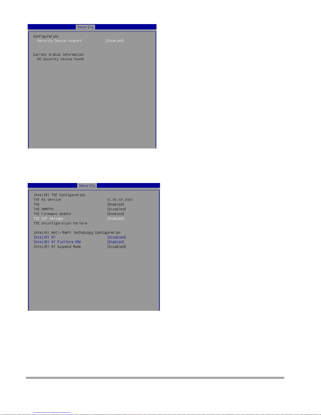
▶
Trusted Computing
▶
Security Device Support
This setting enables/disables BIOS support for security device. When set to [Disable], the OS will not
show security device. TCG EFI protocol and INT1A interface will not be available.
▶
Security Configuration
▶
Intel(R) TXE Configuration
Intel Tr usted Exe cut ion Technology provides highly scalable platform security in physical and virtual
infrastructures.
▶
Intel(R) Anti-Theft Techn ology Configu rat i on
Intel Anti-Theft Technology is hardw are -based technology that can lock a lost or stolen system so that
personal confidential information is protected and inaccessible by unauthorized users.
31
Page 33
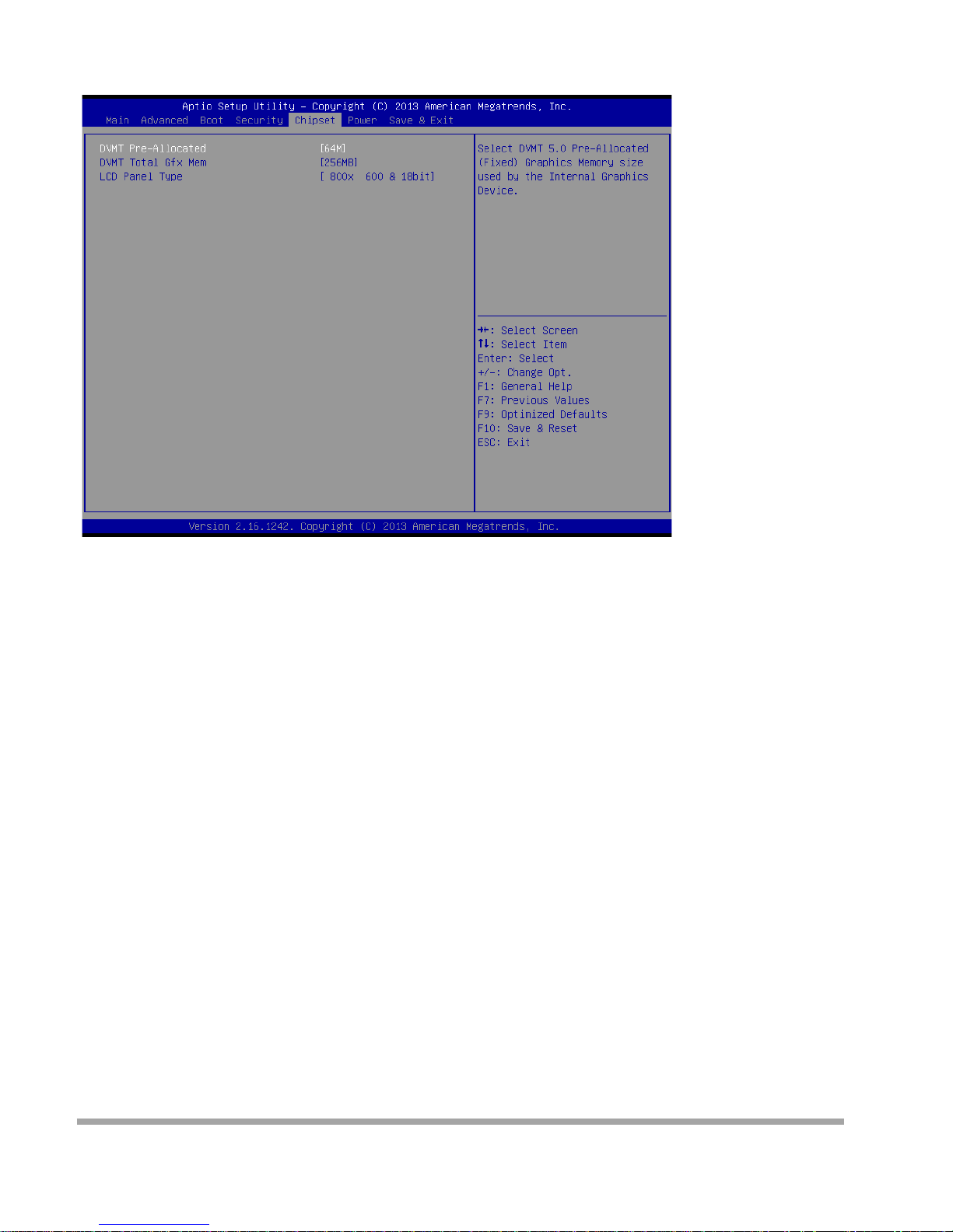
Chipset
▶
DVMT Pre-Allocated
This setting defines the DVMT pre-allocated memory. Pre-allocated memory is the small amount of
system mem ory made available at boot ti m e by the sy s tem BIOS for video. Pre-allocate d m emory is al so
known as locked memory. This is because it is "locked" for video use only and as such, is invisible
and unable to be used by the opera t i ng s ystem.
▶
DVMT Total Gfx Mem
This setting specifies the memory size for DVMT.
▶
LCD Panel Type
This setting allows you to set the resolutio n of the LCD di spla y.
32
Page 34
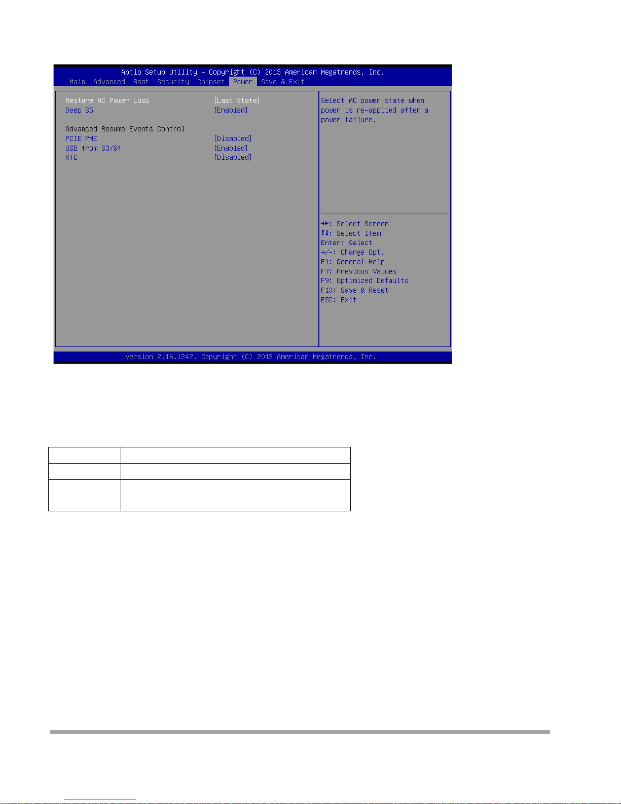
Power
▶
Restore AC Power Loss
This setting specifies whether your system will reboot after a powe r failure or interr upt occurs. Available
set t i ngs ar e:
[Power Off]
Lea ves the computer in the power off state.
[Power On]
Lea ves the computer in the power on state.
[Last State]
Restores the system to the previous status
before power failure or interrupt occurred.
▶
Deep S5
The setting enables/disable s t he Deep S5 power saving mode. S5 i s almost the same as G3 Mechanica l
Off, except that the PSU still supplies power, at a minimum, to the power button to allow return to S0. A
full reboot is req ui red . No pre vious content is retained. Other components may remain power ed so
the comp uter can “wake” on input from the keyboard, clock, modem, LAN, or USB device.
33
Page 35

** Advan ced Resu me Events Con t rol * *
▶
PCIE PME
This field specifie s w hether the system wil l be awakened from pow er saving m odes when activity or input
signal of onboard PCIE PME is detected.
▶
USB fro m S3/ S4
The item allows the activity of the USB device to wake up the system from S3/ S4 sle ep sta te.
▶
RTC
When [Enabled], your can set the date and time at which the RTC (real-time clock) alarm awakens the
system from suspend mode.
34
Page 36
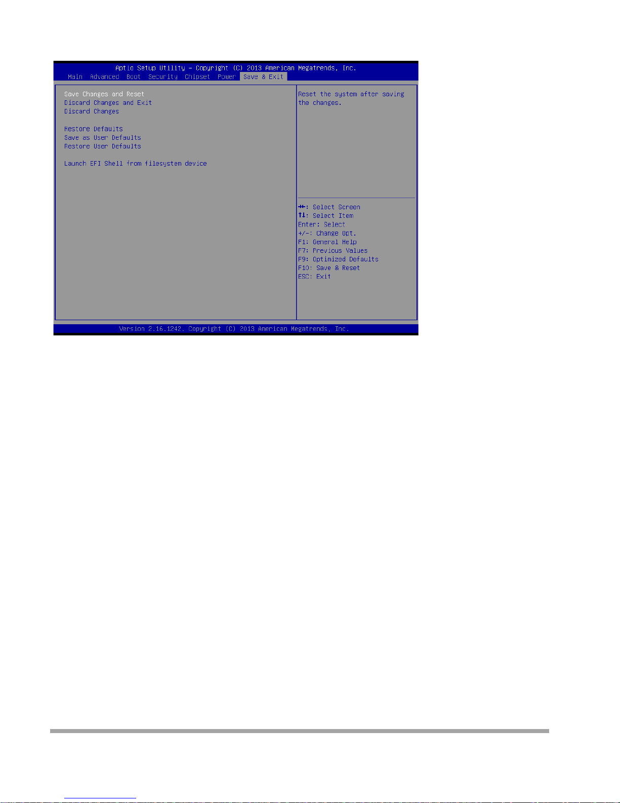
Save & Exit
▶
Save Chan ges and Reset
Save changes to CMOS and reset the system.
▶
Discard Changes and Exit
Abandon all changes and exit the Setup Utility.
▶
Discard Changes
Abandon all changes.
▶
Restore Default s
Use this menu to load the default values set by the motherboard manufacturer specifically for optimal
performan ce of the motherboard.
▶
Save as User Defaults
Save changes as the user’s default profile.
▶
Restore User Defau l t s
Restore the user’s default profile.
▶
Launch EFI Shell from filesystem device
This setting helps to launch the EFI Shell application from one of the available file system devices.
35
Page 37
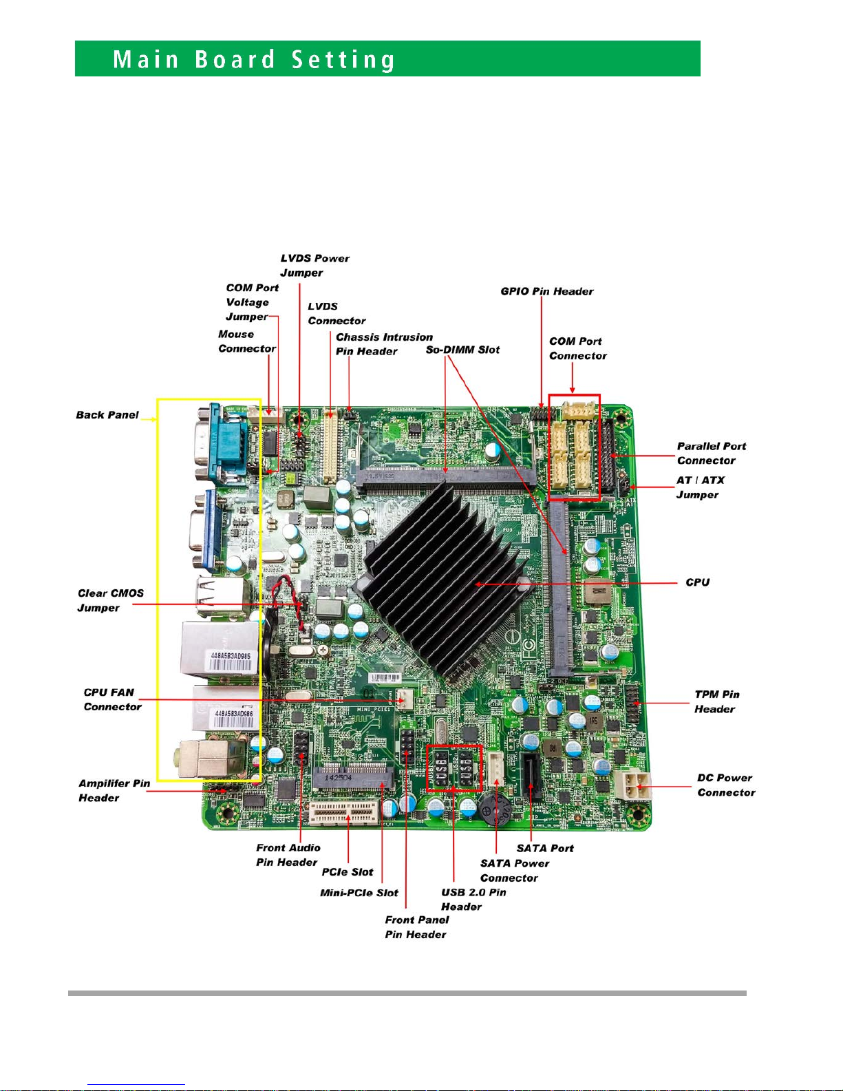
Please unplug the AC power of the adapter before opening any part of the system. Since the standby power
is always on after the adapter is plugged in. It may cause permanent damage to your system when you open
any part of the system.
Installing Peripherals Connectors & Jumpers settings
Motherboard Layout Component Side
6
36
Page 38
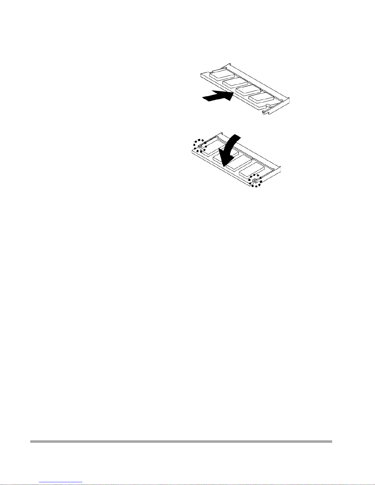
Memory
The SO-DIMM slot is intended for memory modules.
1. Locate the SO-DIMM slot. Align
the notch on the DIMM with the
key on the slot a nd insert the DI MM into t he slot .
2. Push the DIMM ge ntly down-wards
until the slot levers click and lock the
DIMM in place.
3. To uninstall the DIMM, flip t he slot le ver s outwa rd s and the DIMM w il l be releas ed i nstantly.
Important
You can barely see the golden finger if the DIMM is properl y inser ted in t he DIMM slot .
37
Page 39
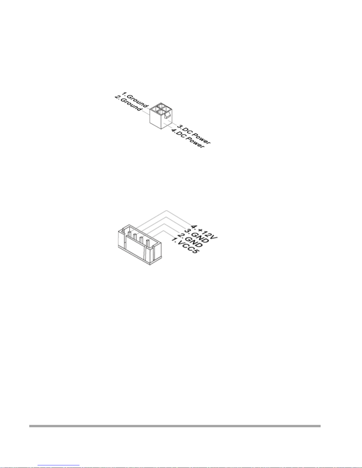
Power Supply
System Power Conn ect or: JPWR1
This connector allows you to connect a power supply. To connect the power sup -ply, make sure the plug
of the power supply i s inser ted in the proper orientation and the pins are aligned. Then push down the
plug firmly into the connector.
SATA Pow er Conn ect or: JPW1
This connector is used to provide power to SATA devices.
Important
Make sur e t hat all power connectors are connected to t he powe r supply to ensure stab le o per at ion of the
motherboard.
38
Page 40
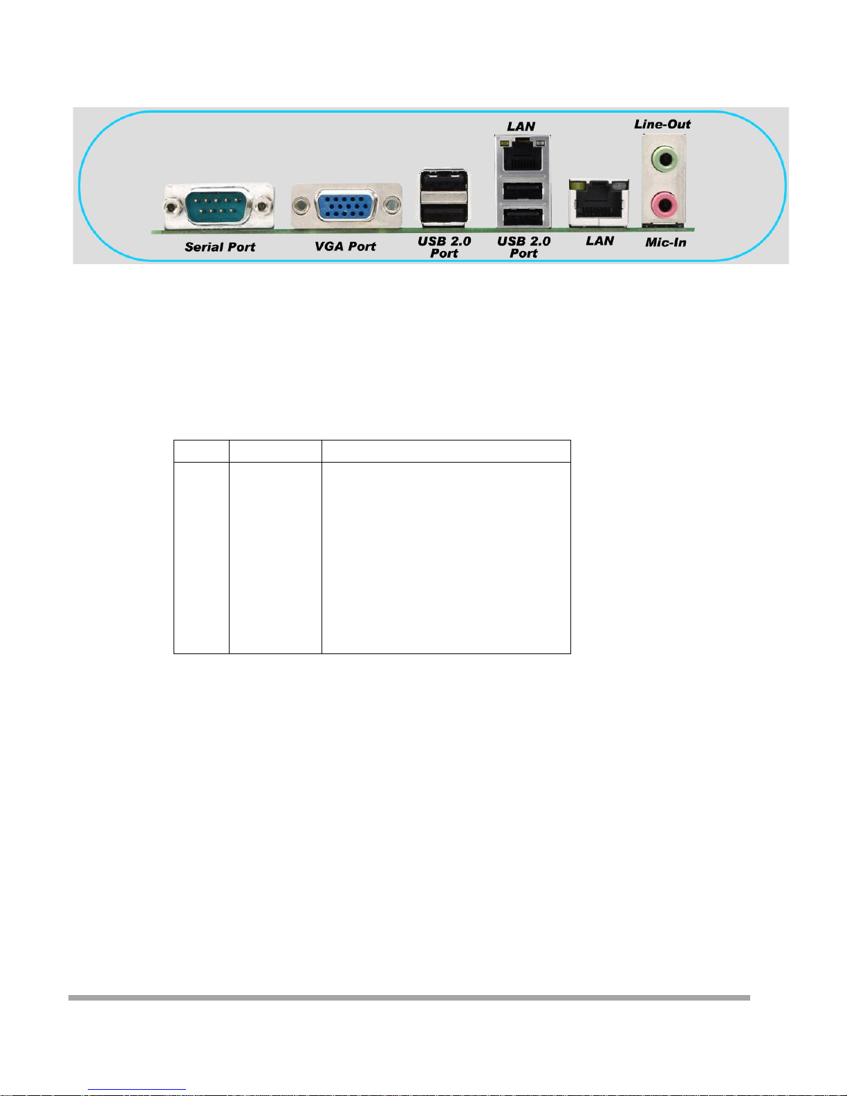
Rear Panel I/O
▶
RS-232 Serial Port
The serial por t is a 16550A high speed communicatio ns por t that sends / re ceives 16 bytes FIFOs.
You can attach a ser ial mou se or other ser ial dev i ces di rectly to the c onnect or.
RS-232
PIN SIGNAL DESCRIPTION
1
2
3
4
5
6
7
8
9
DCD
RXD
TXD
DTR
GND
DSR
RTS
CTS
VCC_COM1
Dat a Carrie r Detect
Receive Dat a
Transmit D ata
Dat a Terminal Read y
Signal Ground
Dat a Set Ready
Request To S end
Clear To Send
Volt age select setting by jumper
▶
VGA
The DB15-pin female connector is provided for monitor.
▶
USB 2.0 Port
The USB (Universal Serial Bus) port is for attaching USB devices such as key-board, mouse, or other
USB-compa t ible devices.
▶
LAN Jack
39
Page 41
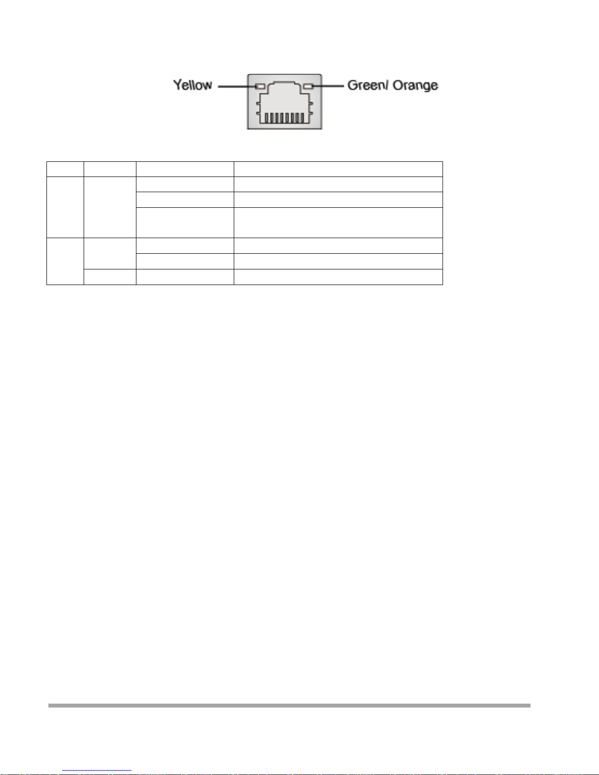
The standard RJ-45 LAN jack is for connection to the Local Area Network (LAN). You can connect a
network cable to it.
LED Color LED State Condition
Left Yellow Off LAN link is not established.
On ( Steady state) LAN link is est ablished.
On (Blinking) The computer is communicating with
another computer on the LAN.
Right Green Off 10 M bit/sec data rate is selected.
On 100 Mb it/sec d ata rate is select ed.
Orange On 1000 Mbi t/sec data rate is selected.
▶
Audio Port
Th es e audio connectors are used f or audio devices. It is e asy to differ entiate bet ween au dio effects
according to the color of audio jacks.
■ Line-Out (Green) - Line Out, is a connector for speakers or headphones.
■ Mic (Pink) - Mic, is a connector for microphones.
40
Page 42
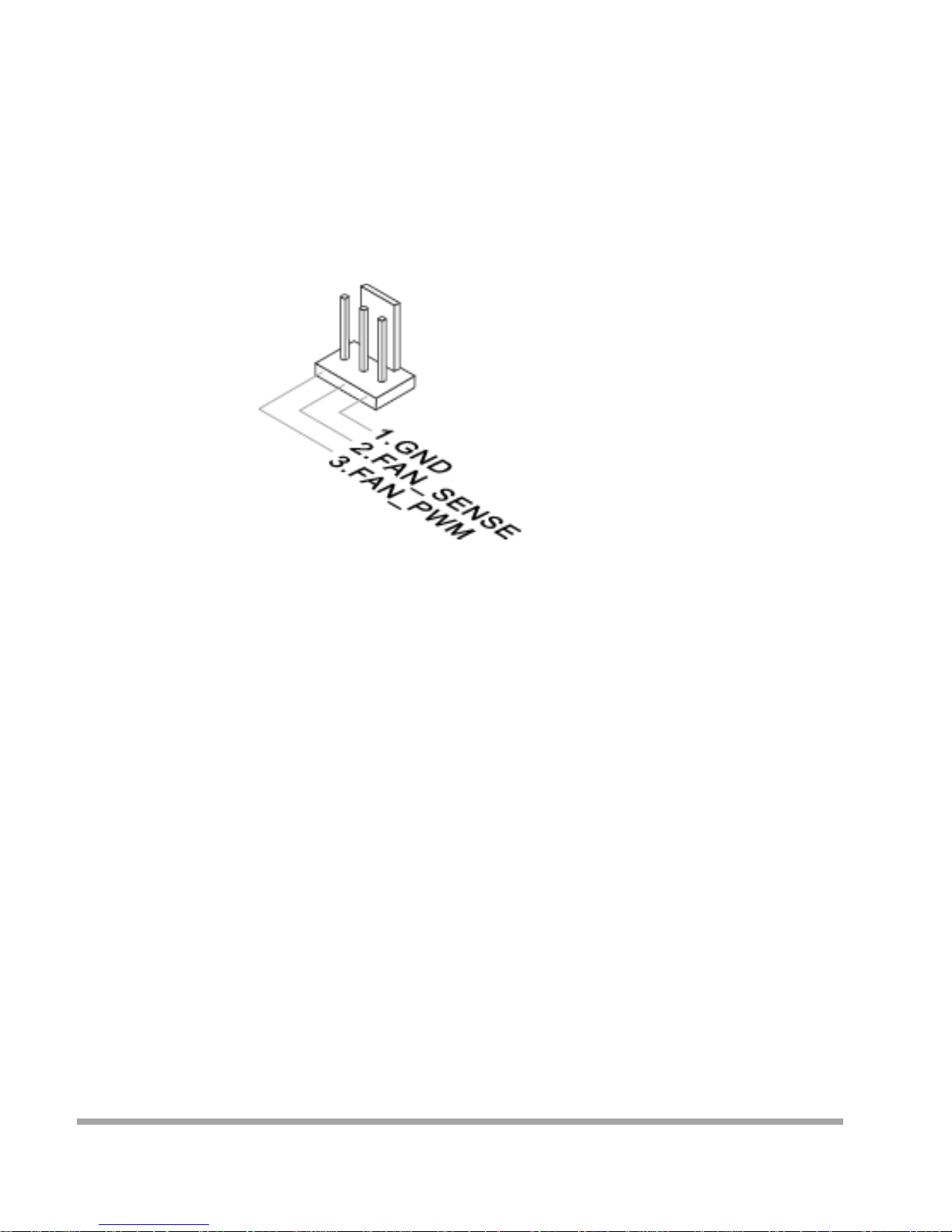
Connector
Fan Power Connector: CPUFAN1
The fan powe r co nnecto r s suppo rt sys tem cool ing fan with +12V. When conne cting the wire to
the connectors, always note that the red wire is t he positive and should be connected to the +12V; t he
black wire is Ground and should be connected to GND. If the motherboard has a System Hardware
Monitor chipset onboard, you must use a specially designed fan with speed sensor to take advantage of
the CPU fan control.
Important
Please refer to the recommended CPU fans at processor’s official website or consult the vendors for
proper CPU coo ling fan.
41
Page 43
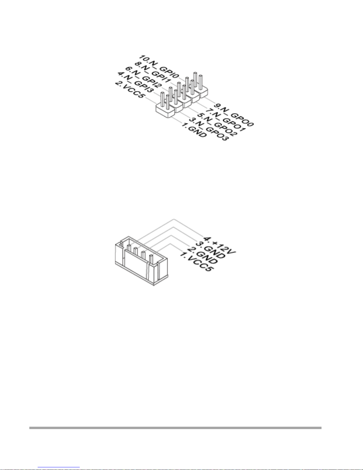
GPIO Pin Header: JGPIO1
This c onnector is provid ed for the Gen eral-Purpose Input / Output (GPIO) peripheral module.
Serial ATA Connector: SATA1
This connector is a high-speed Serial ATA interface port. Each connector can connect to one Serial ATA
device.
Important
Please do not fold the SATA cable into a 90-d egree an gle. Otherwi se, da t a loss may occur du r i ng
transmission.
42
Page 44
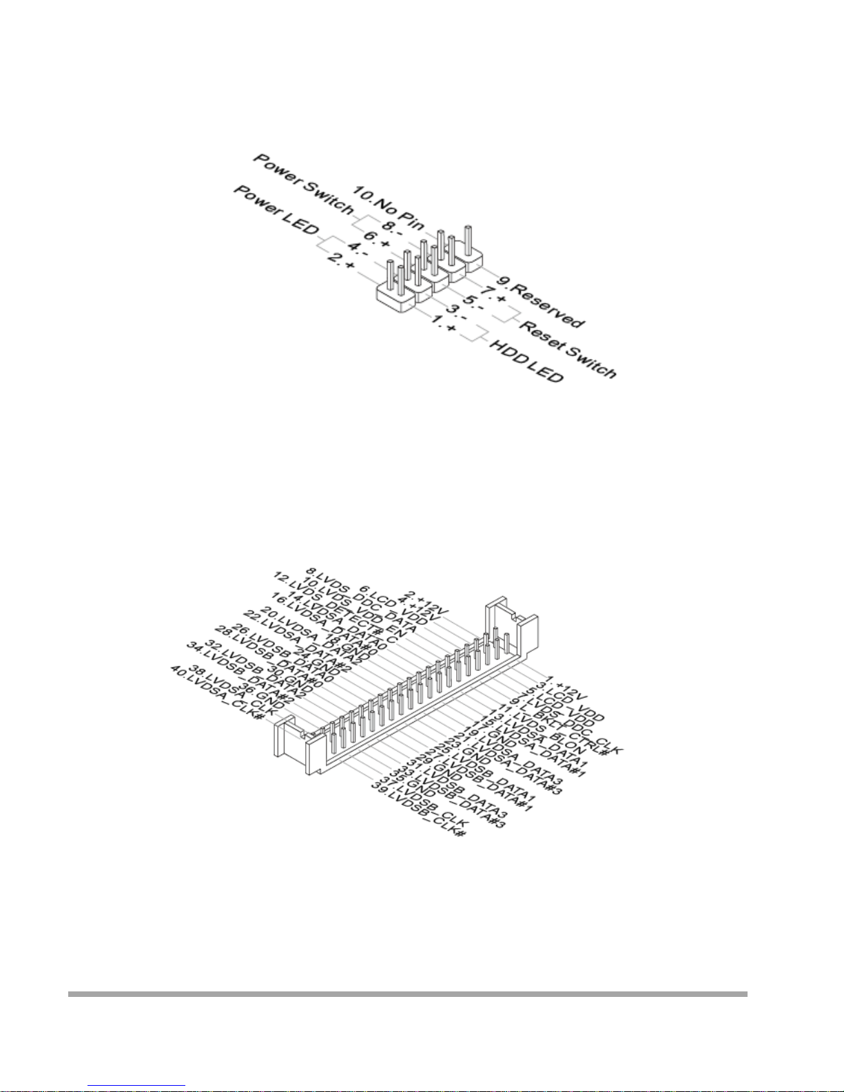
Front Panel Connec tor: JFP1
This front panel connector is provided for electrical connection to the front panel switches & LEDs
and is compliant with Intel Front Panel I/O Connec t i vit y Desig n Guide .
LVDS Connector: JLVDS1
The LVDS (Low Voltage Differential Signal) connector provides a digital interface typically used with flat
panels. Afte r connecting an LVDS interfa ce flat panel to the J LVDS1, be sure to check the panel
datasheet and set the LVDS jumper to proper power volta ge.
Important
Pin 12 is a detect pin. When using a customized LVDS cable, pi n 12 should be a signal gro und with a low
impedance. Otherwise , LVDS will not function.
43
Page 45
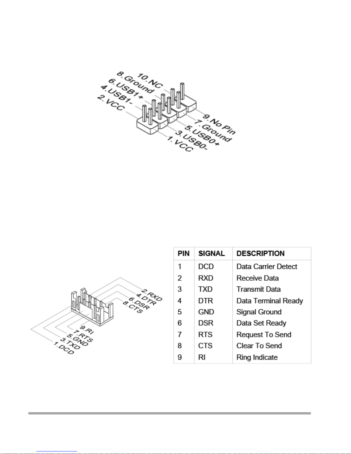
USB 2.0 Connector: JUSB1, JUSB2
This connecto r , comp liant with Intel I/O Connecti vit y Desig n G uide, is ideal for connecting
high-speed USB int er fa ce peripherals such as USB HDD, digital cameras, MP3 players, printers,
modems and the like.
Important
Note that th e p i ns of VCC and GND must be connected c or rect ly to av oid poss ible d amage.
Serial Port Connector: COM2 ~ COM6
This connecto r is a 16550A hig h speed com munications port that sends/ re ce i ves 16 byte s FIFOs.
You can attach a serial device to it.
44
Page 46
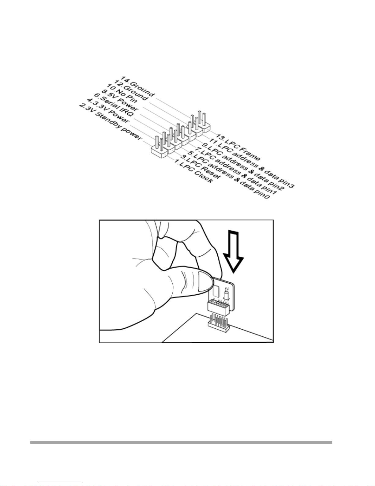
TPM Module Connector: JTPM1
This connector connects to a TPM (Trusted Platform Module) module (optional). Please refer to the TPM
security platf orm manual for more details.
45
Page 47
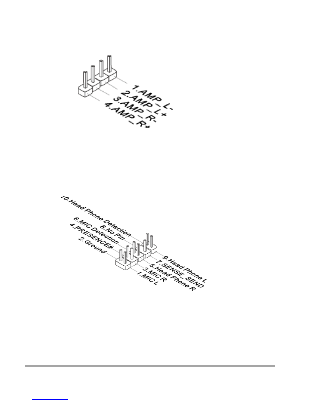
Audio Amplifi er Pin header: JAM P 1
The JAMP1 is used to co nnect audio amplifiers to enhance audio performance.
Front Audio Connector: JAUD1
This connector allows you to connect the front panel audio and is compliant with Intel Front Panel I/O
Connectivity Design Guide.
46
Page 48
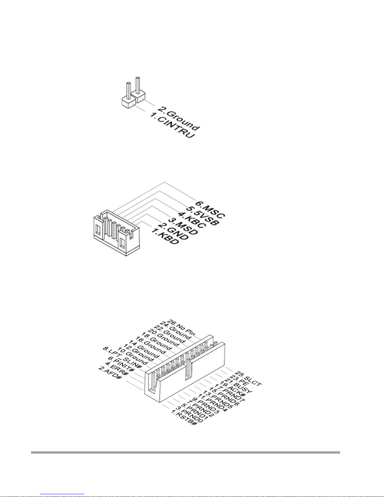
Chassis Intrusion Pin Header: JCASE1
This connecto r co nnect s to t he chassis intrusion switch cable. If the computer case is opened,
the chassis intrusion mechanism wi l l be act i vated . The system wil l record this intrus ion an d a w ar ning
message will flash on screen. To clear the warning, you must enter the BIOS utility and clear the record.
Keyboard/Mouse Connector: JKBMS1
This connector is provid ed to con nect a k eyboar d and a mou se.
Parallel Port Connector: JLPT1
Th e m ai nboard provides a 26-pin header for connection to an optional parallel port bracket. The parallel
port is a standard printer port that supports Enhanced Parallel Port (EPP) and Exte nded Capabilities
Parallel Port (ECP) mode.
47
Page 49
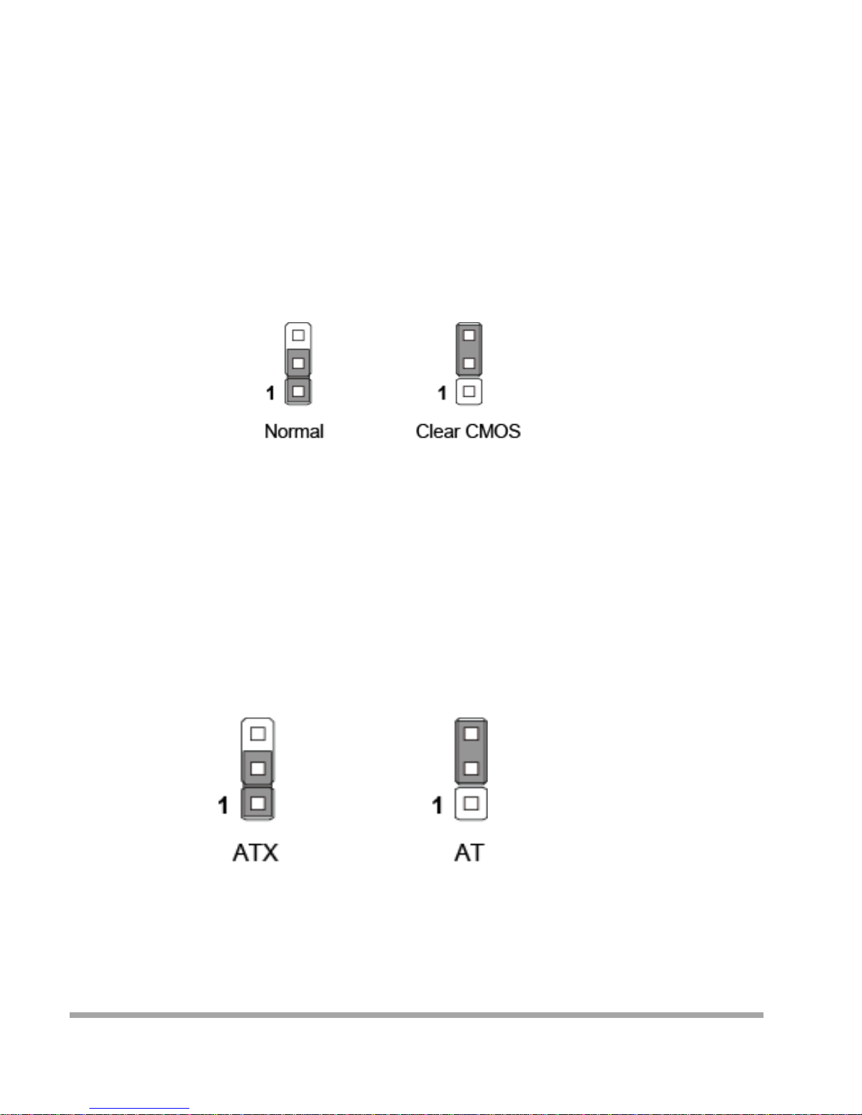
Jumper
Important
Av oid adjus ting jumpers when the syst em is on; i t will damage the motherbo ard.
Clear CMOS Ju mper: JCMOS1
There is a CMOS RAM onboa rd t ha t has a power suppl y from an external battery to keep the data of
system co nfig ura tion. With the CMOS RAM, the system can automatically boot OS ever y time it is
turned on. If you want to clear the system configuration, set the jumper to clear data.
Important
You can clear CMOS by shorting 2-3 pin while the system is off. Then ret ur n to 1-2 pin position.
Avoid clearing the CMOS while the system is on; it will damage the motherboard.
AT/ATX Select Jumper: JATX1
This jumper allows users to select betwee n AT and ATX power.
48
Page 50
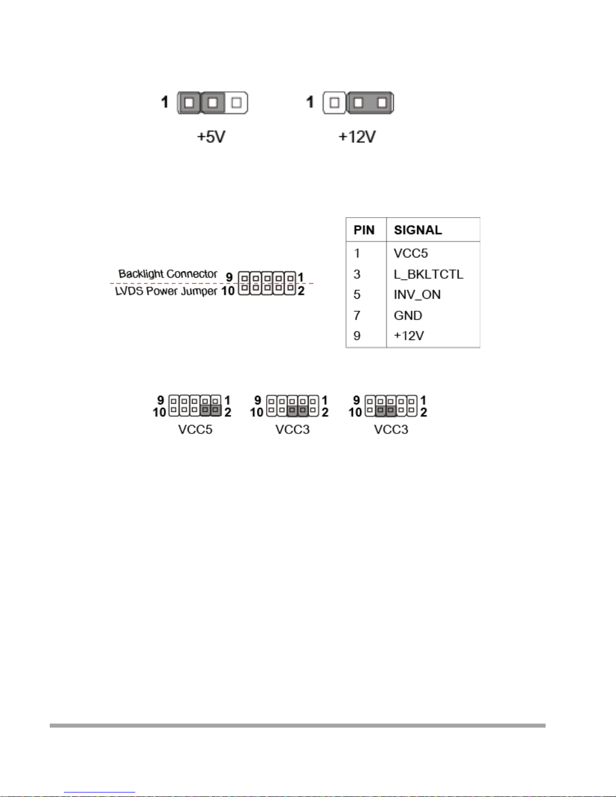
Serial Port Power Jumper: JCOMP1
This jumper specifies the operation voltage of t he COM1 se rial port.
Backlight Header & LVDS Power Jumper: JLCD1
Important
Pin 2, 4, 6, 8 are panel power vol tage select pins while pin 1, 3, 5, 7 are inverter voltage and
control pins.
49
Page 51

Slot
PCIe (Periph eral Component Interconnect Express) Slot
The PCI Express slot supports PCIe interface expansion cards.
Mini-PCIe (Peripheral Component Interconn ect Express) Slot
The Mini-PCIe slot is provided for wireless LAN card, TV tuner card, Robson NAND
Flash card and mSATA devices.
Important
When adding or removing expansion card s, ma ke sure that yo u unplug t he power suppl y first.
Meanwhile, read the documentation for the expansion card to configure any necessary hardware or
software settings for the expansion card, such as jumpers, switches or BIOS configuration.
50
Page 52
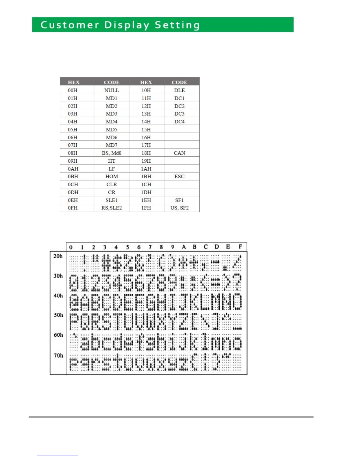
Character Font Table
A. Control code set
B. U.S.A. font set
7
51
Page 53
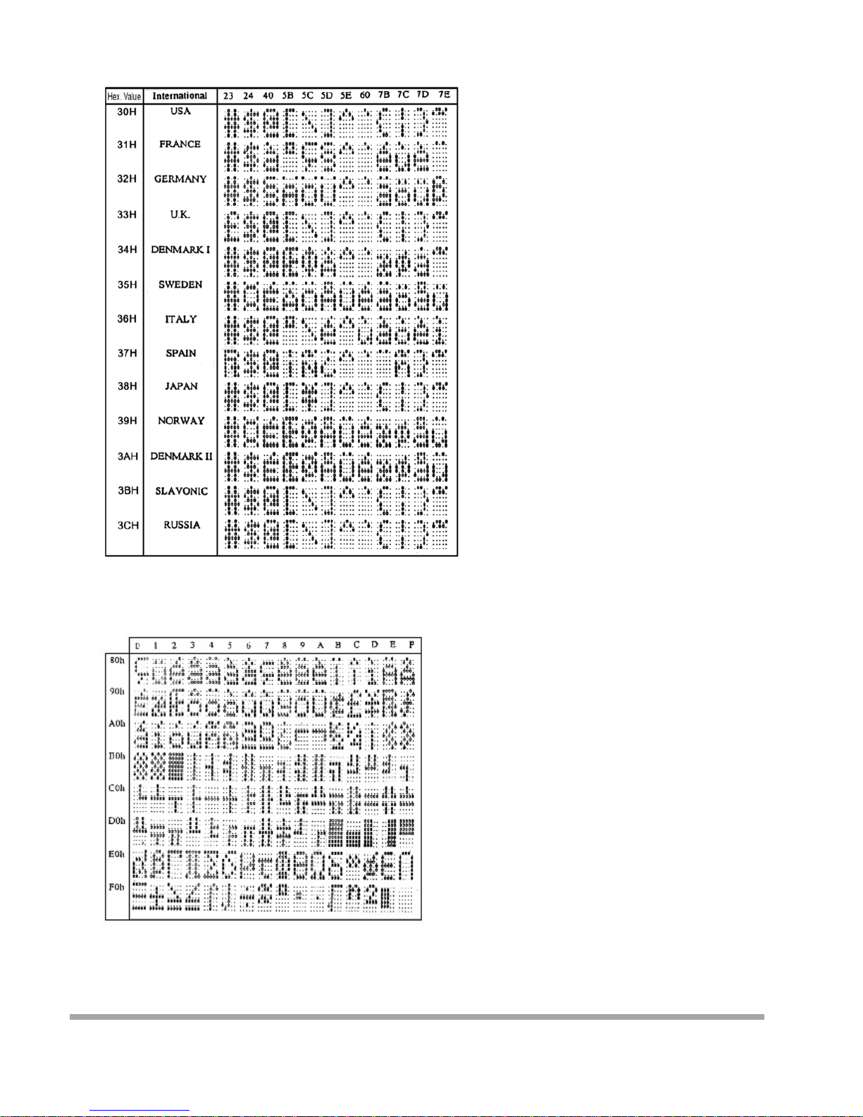
C. International character selection
ASCII CODE
3DH: Standa rd Europe international font set
52
Page 54
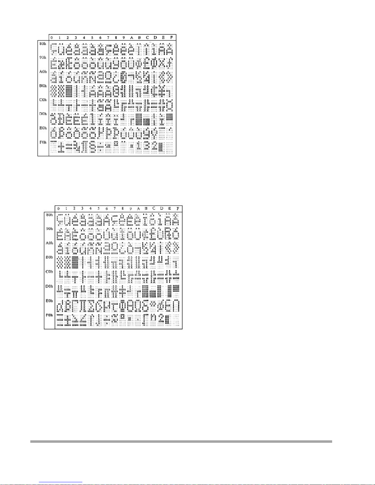
3EH: Multing ual international fo nt set
3FH: Portuguese international font set
53
Page 55
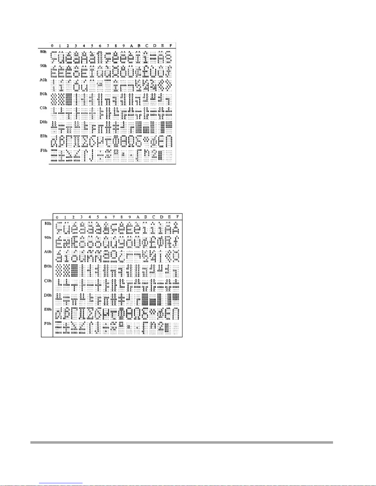
40H: Canadian French internatio nal fo nt set
41H: NORDIC int er nat ional font set
54
Page 56
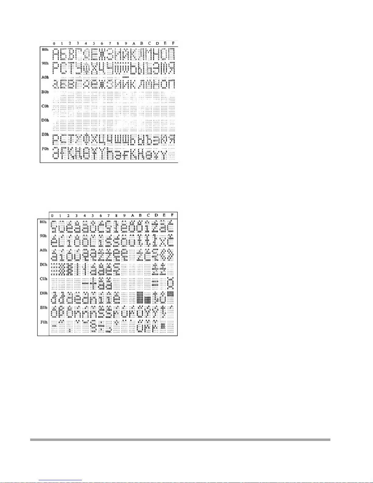
42H: RUSSIA fo nt set
43H: SLAVONIC Font s et
55
Page 57
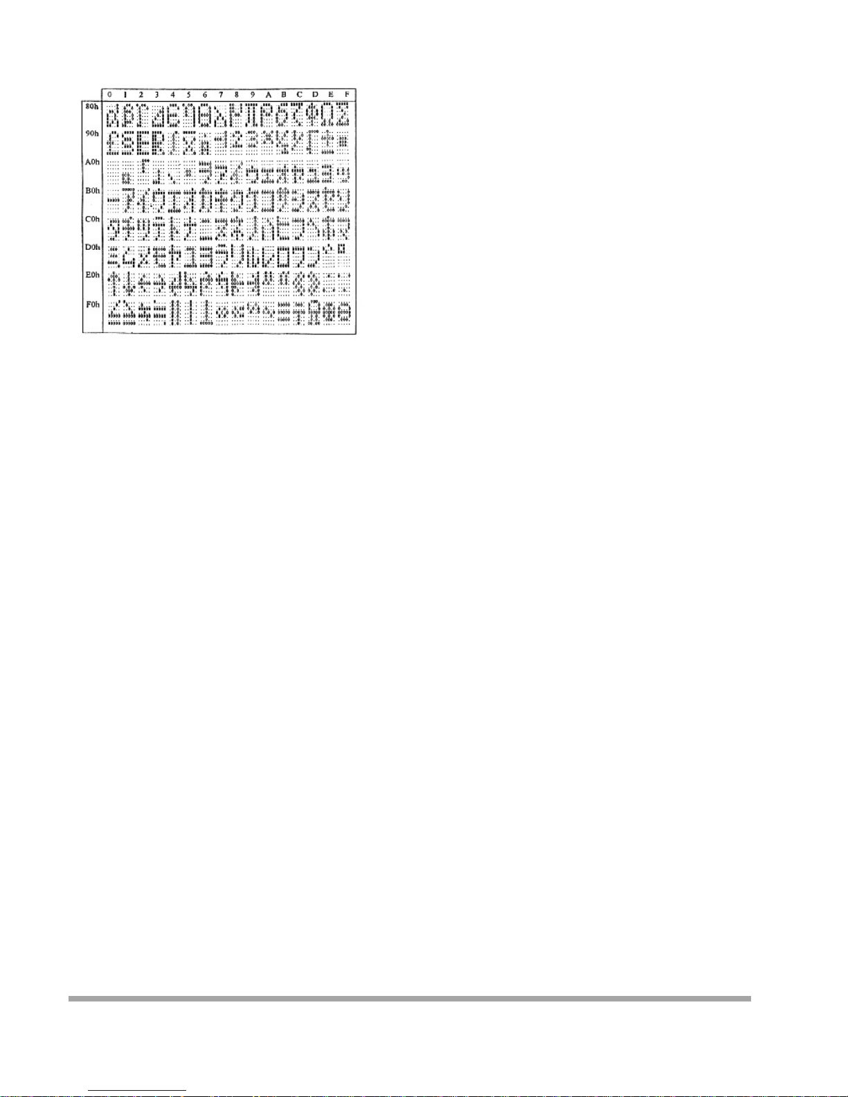
44H: Katakana font set
56
Page 58
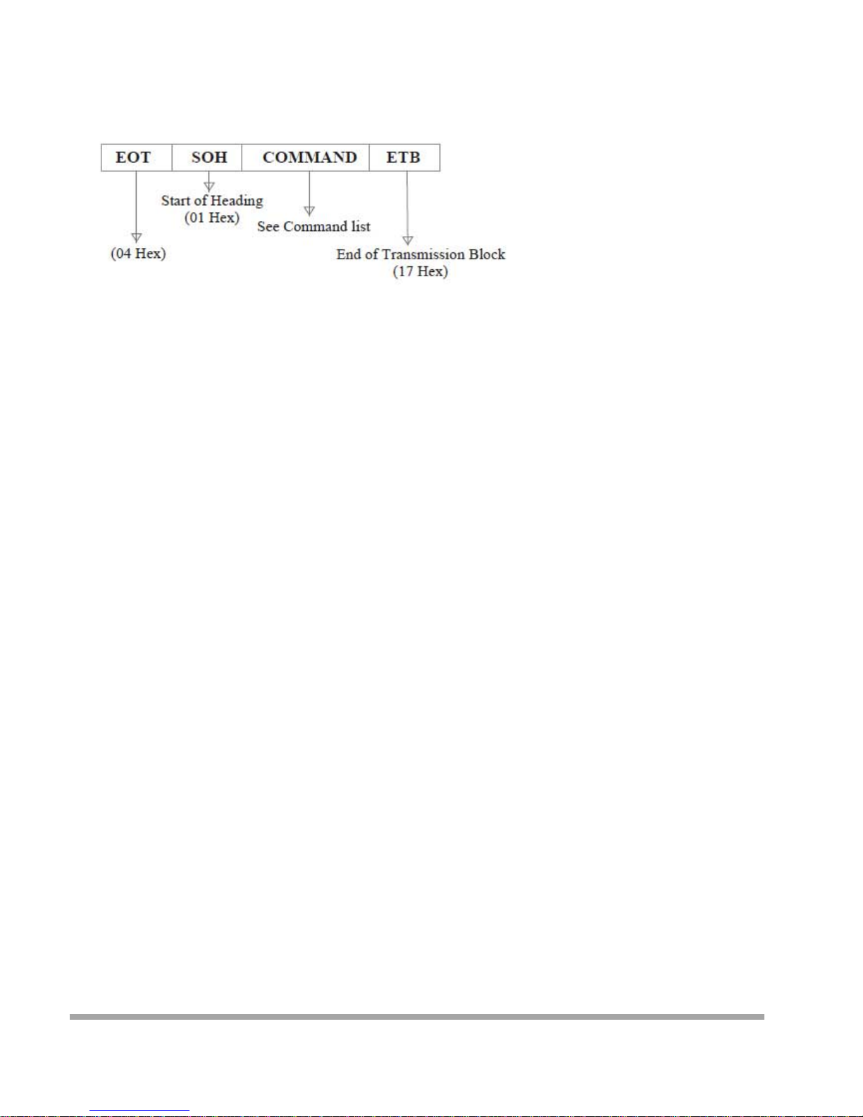
System Commands
Command Format
Command List
A. Set Baud Ra te
COMMAND: B
COMPUTER:EOT SOH 'B' 'BAUD RATE' 'N' ETB
ASCII (04H) (01H)(42H) (31H~37H)(4EH)(17H)
Byte 1 1 1 1 1 1
DISPLAY: ACK (or NACK if failed)
ASCII (06H) (15H)
Byte 1 1
Note: Baud rates
31H: 9600
32H: 4800
33H: 2400
34H: 1200
35H: 600
36H: 300
37H:19200
57
Page 59
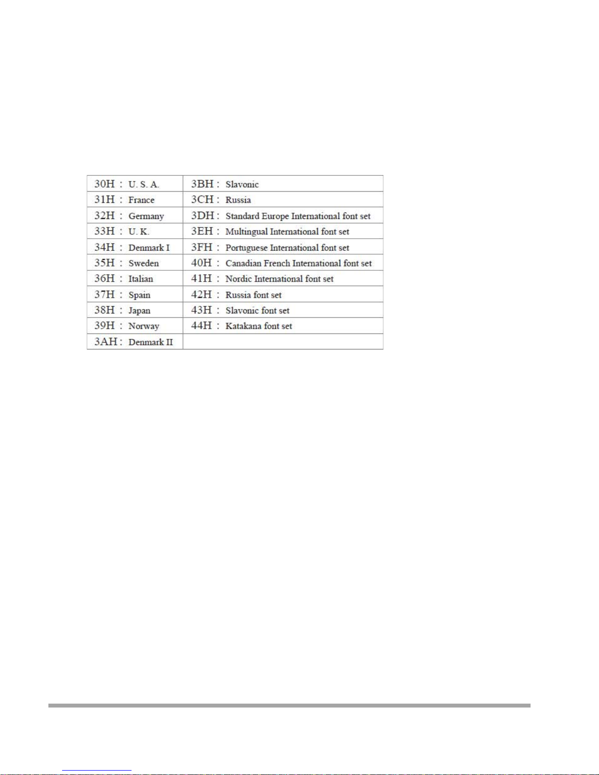
B. Select international code table
COMMAND: I
COMPUTER:EOT SOH 'I' 'CHAR' ETB
ASCII(04H)(01H)(49H)(30H~44H)(17H)
Byte 1 1 1 1 1
DISPLAY: ACK (or NACK if failed)
ASCII (06H) (15H)
Byte 1 1
Note : International Character Cod e
C. Save the curren t vi ew message
(Sa ve Demo view data)
COMMAND: S
COMPUTER:EOT SOH 'S ' 'Layer' ETB
ASCII(04H)(01H)(53H)(31H~33H)(17H)
Byte 1 1 1 1 1
DISPLAY: ACK (or NACK if failed)
ASCII (06H) (15H)
Byte 1 1
Note : 31H: Layer 1 / 32H: Layer 2 / 33H: Layer 3
D. Set cursor p ositi on
COMMAND: P
COMPUTER: EOT SOH 'P' 'Position' ETB
ASCII (04H) (0 1H) (50H) (31H~58H) (17H)
Byte 1 1 1 1 1
DISPLAY: ACK (or NACK if failed)
ASCII (06 H ) (15H)
Byte 1 1
58
Page 60

Note: The cursor can be set to the position from 1 to 40
Position 1 means the upper left corner position.
Position 20 means the upper right corner position.
Position 21 means the lower left corner position.
Position 40 means the lower right corner position.
E. Clear display range
COMMAND: C
COMPUTER: EOT SOH 'C' 'START' 'END' ETB
ASCII (04H)(01H)(43H)(31H~58H)(31H~ 58H)(17H)
Byte 1 1 1 1 1
DISPLAY: ACK (or NACK if failed)
ASCII (06H) (15H)
Byte 1 1
Note: Some part of the cu r rent view messages can be
cleared by this COMMAND. It can start clearing
between position 1 and position 40.
F. Display the saved DEMO message
COMMAND: D
COMPUTER: EOT SOH 'D' 'Layer' 'Mode' ETB
ASCII (04H)(01H)(44H)(31H~37H)(31H~ 33H)(17H)
Byte 1 1 1 1 1
DISPLAY: ACK (or NACK if failed)
ASCII (06H) (15H)
Byte 1 1
Note:
a) There are three layers of saved view messages as described on COMMAND "S"
b) There are two modes of display:
Mode 1 is running the saved messages from right to left, which is a horizontal scroll mode.
Mode 2 is running the saved messages from the lower line to the upper line, which is a vertical scroll mode.
c) For display layers:
select 31H means display the message saved on layer 1.
select 32H means display the message saved on layer 2.
select 33H means display the message saved on layer 1+ layer2.
select 34H means display the message saved on layer 3.
select 35H means display the two messages saved on layer 1 + layer 3.
select 36H means display the two messages saved on layer 2 +layer 3.
select 37H means display all the messages saved on layer 1 +layer 2 + layer 3.
d) For display modes,
select 31H means display the message with Mode 1.
select 32H means display the message with Mode 2.
59
Page 61
select 33H means display the message with Mode 1+Mode 2.
For this Demo display function, you must have saved the message by COMMAND "S" previously, For example,
select 37H for displaying layers and select 33H for displaying modes, DSP would display all the three messages saved on
layer 1+ layer 2 + layer 3 with both Mode 1 + Mode 2 displaying modes.
e) Any new message from the computer would stop this Demo
display function and DSP would display that new message from the computer.
G. Select the Command Mode
COMMAND: M
COMPUTER: EOT SOH 'M' 'Mode' ETB
ASCII (04H) (01H) (4DH)(30H~38H) (17H)
Byte 1 1 1 1 1
DISPLAY: ACK (or NACK if failed)
ASCII (06H) (15H)
Byte 1 1
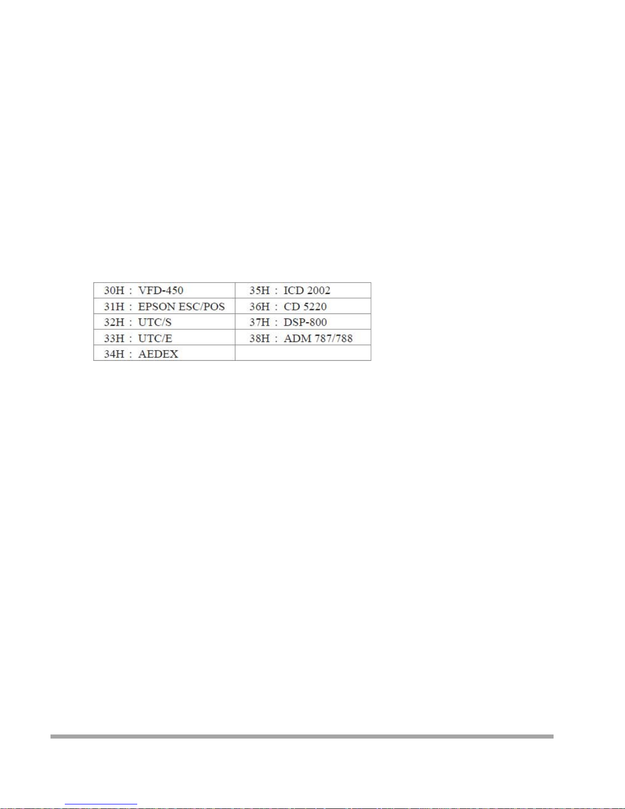
Note: Command Modes Selection
H. Set all default
COMMAND: X
COMPUTER: EOT SOH 'X' ETB
ASCII (04H) (0 1H) (58H) (17H)
Byte 1 1 1 1
60
Page 62

Transmission method
Each ASCII character is transmitted with
1 start bit
8 data bits
1 stop bit
No parity
Note: You may generate your own application software to run the display according to the standard
RS-232C communication protocols and the SOFTWARE CONTROL information listed on this chapter.
61
Page 63
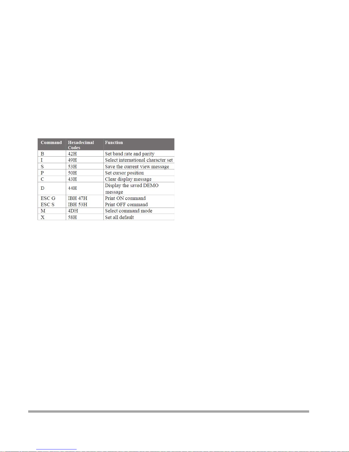
Command Modes
The c ommand modes can be selected with the Demo Software.
Mode 0: Default
Mode 1: EPSON Esc/POS
Mode 2: UTC S tandard
Mode 3: UTC E nhanced
Mode 4: AEDEX
Mode 5: ICD 2002
Mode 6: CD 5220
Mode 7: DSP -800
Mode 8: ADM 787/788
Mode 0: Default
62
Page 64
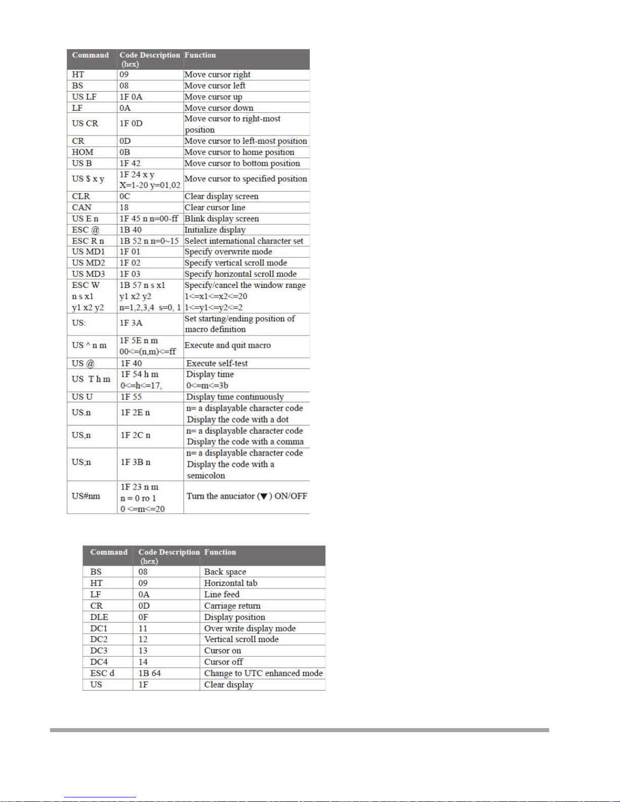
Mode 1 : EPSO N Es c /POS mode
Mode 2: UTC Standard mode
63
Page 65
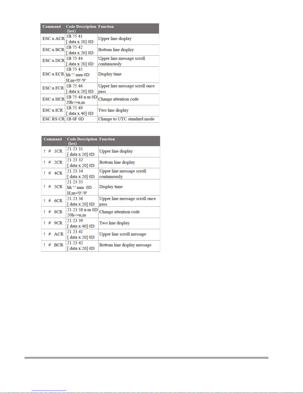
Mode 3: UTC enha nced mod e
Mode 4: AEDEX mode
64
Page 66
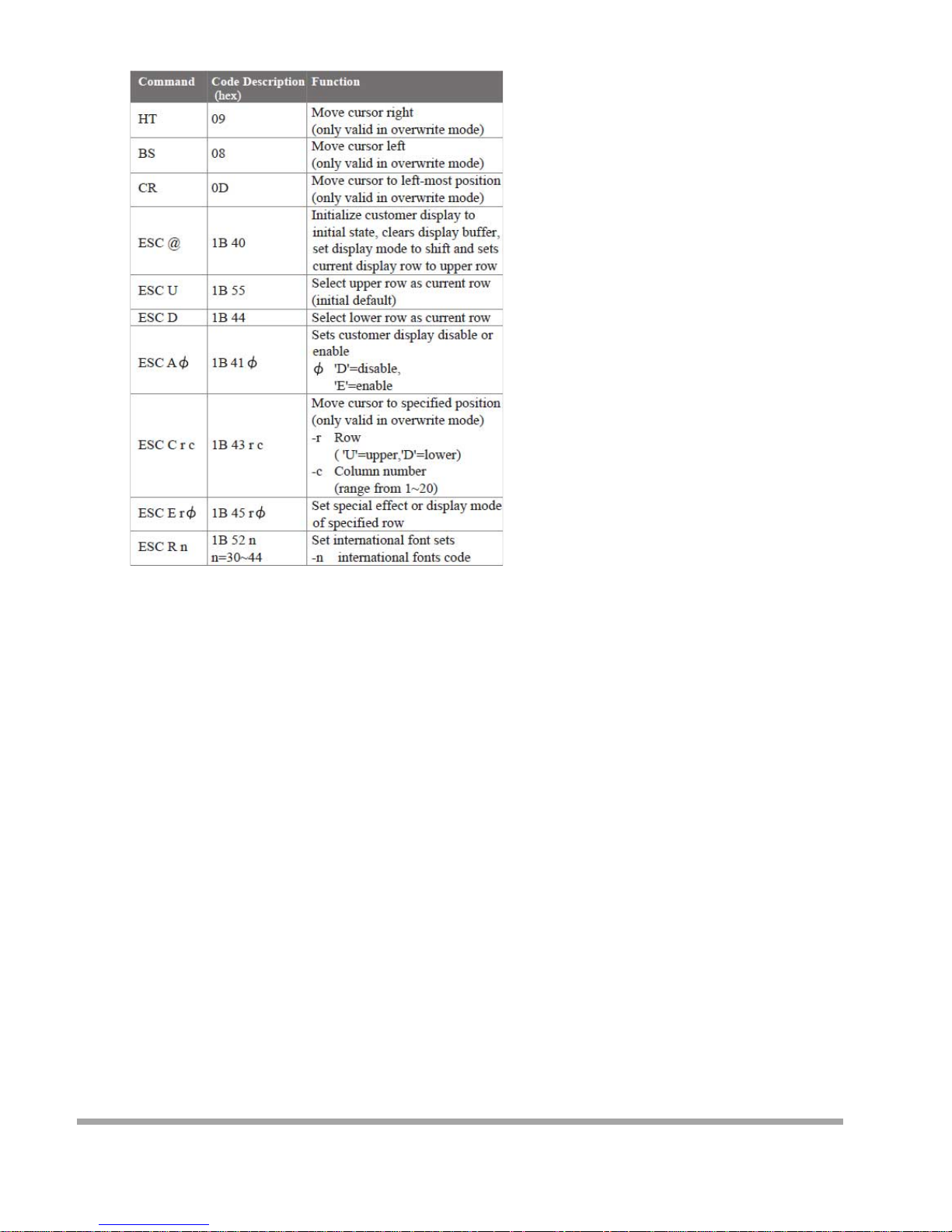
Mode 5: ICD 2002 mode
REMARK)* Using command "ESC E r Φ", the value of parameter:
r 58= all rows
55= upper row
44= lower row
Φspeci al fun c tion , th e valu e is on e of
30= shift mode (default)
31= r otation mode
32= blink mode
33= clear this row and switch to shift mode
34= overwrite mode
35= vertical mode
65
Page 67
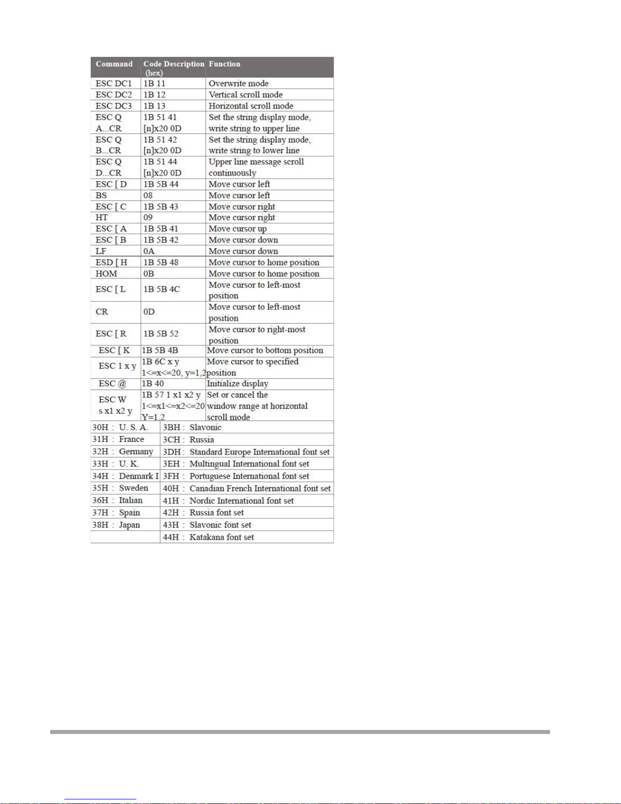
Mode 6: CD 5220 standar d mod e
66
Page 68
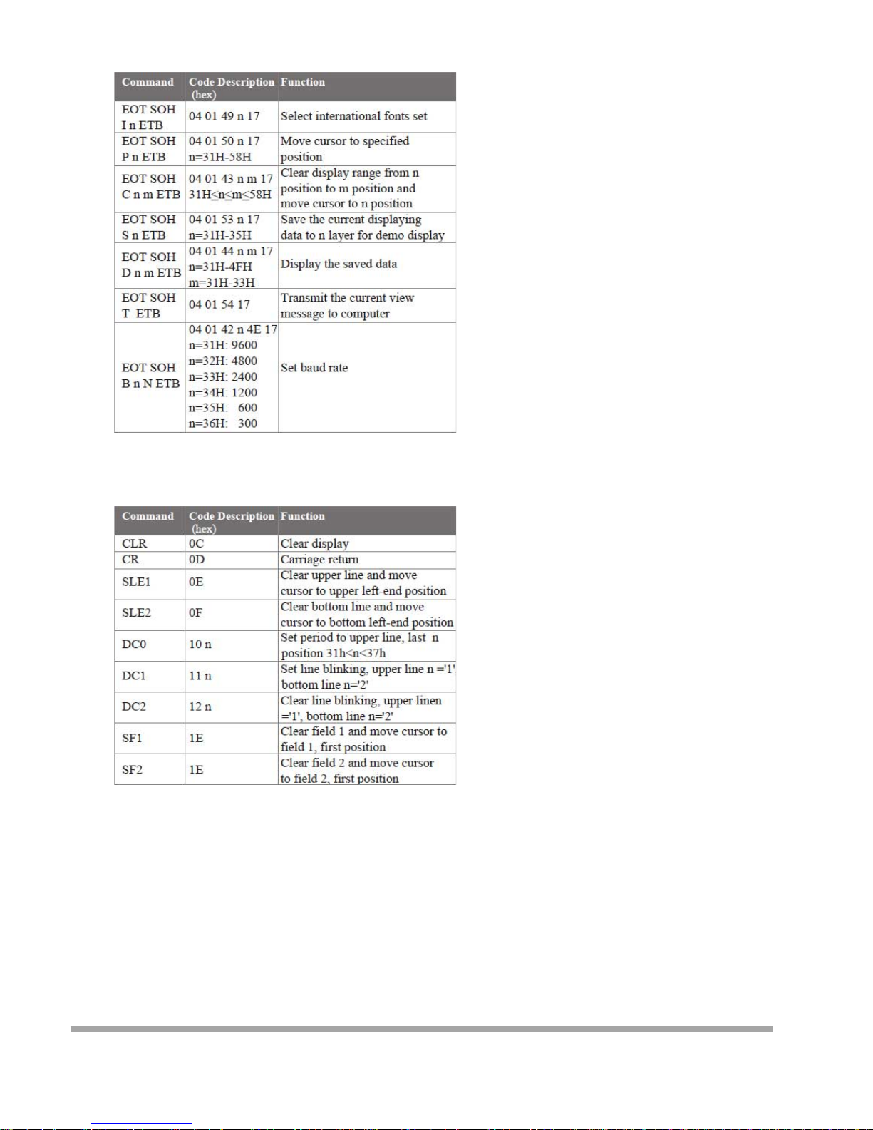
Mode 7: DSP-800 mode
Mode 8: ADM 787/788 mode
67
Page 69
CE MARK
This device compiles with the requirements of the EEC directive 89/336/EEC with regard to
“Electromagnetic compatibility” and 73/23/EEC “Low Voltage Directive”
FCC This device complies with part 15 of the FCC rules. Operation is subject to the following two
conditions:
(1)This device may not cause harmful interference.
(2)This device must accept any interference received, including interference that may cause
undesired operation.
CAUTION ON LITHIUM BATTERIES
There is adapter of explosion if the battery is replaced incorrectly. Replace only with the same or equivalent type
recommended by the manufacturer. Discard used batteries according to the manufacturer’s instructions.
LEGISLATION AND WEEE SYMBOL
2002/96/EC Waste Electrical and Electronic Equipment Directive on the treatment, collection,
recycling and disposal of electric and electronic devices and their components.
The crossed dustbin symbol on the device means that it should not be disposed of with other
household wastes at the end of its working life. Instead, the device should be taken to the
waste collection centers for activation of the treatment, collection, recycling and disposal
procedure.
To prevent possible harm to the environment or human health from uncontrolled waste disposal,
please separate this from other types of wastes and recycle it responsibly to promote the sustainable reuse of
material resources.
Household users should contact either the retailer where they purchased this product, or their local government
office, for details of where and how they can take this item for environmentally safe recycling.
Business users should contact their supplier and check the terms and conditions of the purchase contract.
This product should not be mixed with other commercial wastes for disposal.
68
 Loading...