

Page 1

1
Introduction..................................................................... 3
Installation....................................................................... 4
Pin Assignments............................................................. 5
Method of Programming................................................. 7
Interface sele ction......................................................... 10
Reading Mode................................................................1 1
RS –232 Communication Para meters............................12
Keyboard Wedge Parameters.........................................14
Output Characters Parameters..................................... 16
Wa nd Emulation............................................................ 1 7
OCIA Mode Para meters................................................ 18
Bar Code Type Selection.............................................. 21
UPC/EAN/JAN.............................................................. 24
Code 39........................................................................ 26
Code 128...................................................................... 28
Interleave 25................................................................. 30
Industrial 25................................................................... 3 2
Matrix 25........................................................................ 3 4
CODABAR/NW7........................................................... 36
Code 93......................................................................... 38
Code 11............... ......................................................... 40
MSI/PLESSEY............................................................... 42
BC 412.......................................................................... 44
China Postage..............................................................46
Language Sele ction....................................................... 48
Bar Code ID.................................................................. 50
Table of Contents
Page 2

2
Reading Level.............................................................. 53
Accuracy...................................................................... 53
Sensitivity of Continuous Reading Mode..................... 53
Buzzer Beep Tone........................................................ 54
PnP/Notebooks ........................................................... 54
Reverse Output Chara cters.......................................... 54
Setup Deletion.............................................................. 55
Setup Insertion.............................................................. 59
Appendix A..................................................................... 63
Appendix B.....................................................................64
Appendix C.....................................................................68
Table of Contents
Page 3

3
Thank you for selecting Birch barcode input product, CD108E CCD barcode re ader . The rea der is equipped with up
to date optical technology. It auto-discrimina tes nearly
twenty different kinds of barcode symbologies. Birch also
provides other barcode related products to meet your
application.
The easily plug and play design of the keyboard wedge
interface, provides a flexible solution to your application to
explore the magic of the barcode system.
This manual provides an easily method to modify the
decoding option s and interface protocols of the CD-108E
by scanning the barcode in the manual. Before starting,
please make sure that the barcode reader is properly
powered. For PC keyboard emulation type interfa ce, power
is directly come from the system. For RS-232 or other nonPC keyboard emulation type interface, a n external power is
always needed.
Codes Read
ALL UPC/EAN/JAN , Code 39, Code 39 Full ASCII, Code
128, Interleave 25, Industri al 25, Matrix 25, CODABAR/NW7,
Code 1 1, BC 412,MSI/PLESSEY , Code 93, Chin a Postage,
Code 32
Introduction
Page 4

4
Installation
Installing the Keyboard Wedge Reader
T o in stall a keyboard wedge re ader , f ollow the ste ps below:
1. Turn off the power of the PC or Terminal.
2. Un plug keyboard from the PC or Terminal.
3. Make sure you have the Y Cable with appropriate
connector type for your PC or T ermin al.
4. Connect Scanner to your PC or Terminal
5. Connect the keyboard connector to the female connector
of the Y cable
6. Turn on the power of PC or Terminal.
If the installation is successful , the Green LED light on the
top of the rea der should light up, a nd you should he ar three
beeps from rea der.
Installing the RS232 Reader
To install a RS232 reader , follow the ste ps below :
1. Turn off the power of the PC or Terminal.
2. Make sure the connector type from RS232 to the PC or
Terminal is correct.
3. Plug AC Ada ptor connector into connector of the re ader.
4. Turn on the power of PC or Terminal.
5. Setup the Interface of the reader to RS232 mode by
scanning the barcode in the Interfa ce Sele ction section.
If the installation is successful, the Green LED light on the
top of the rea der should light up, a nd you should he ar three
beeps from rea der.
Page 5
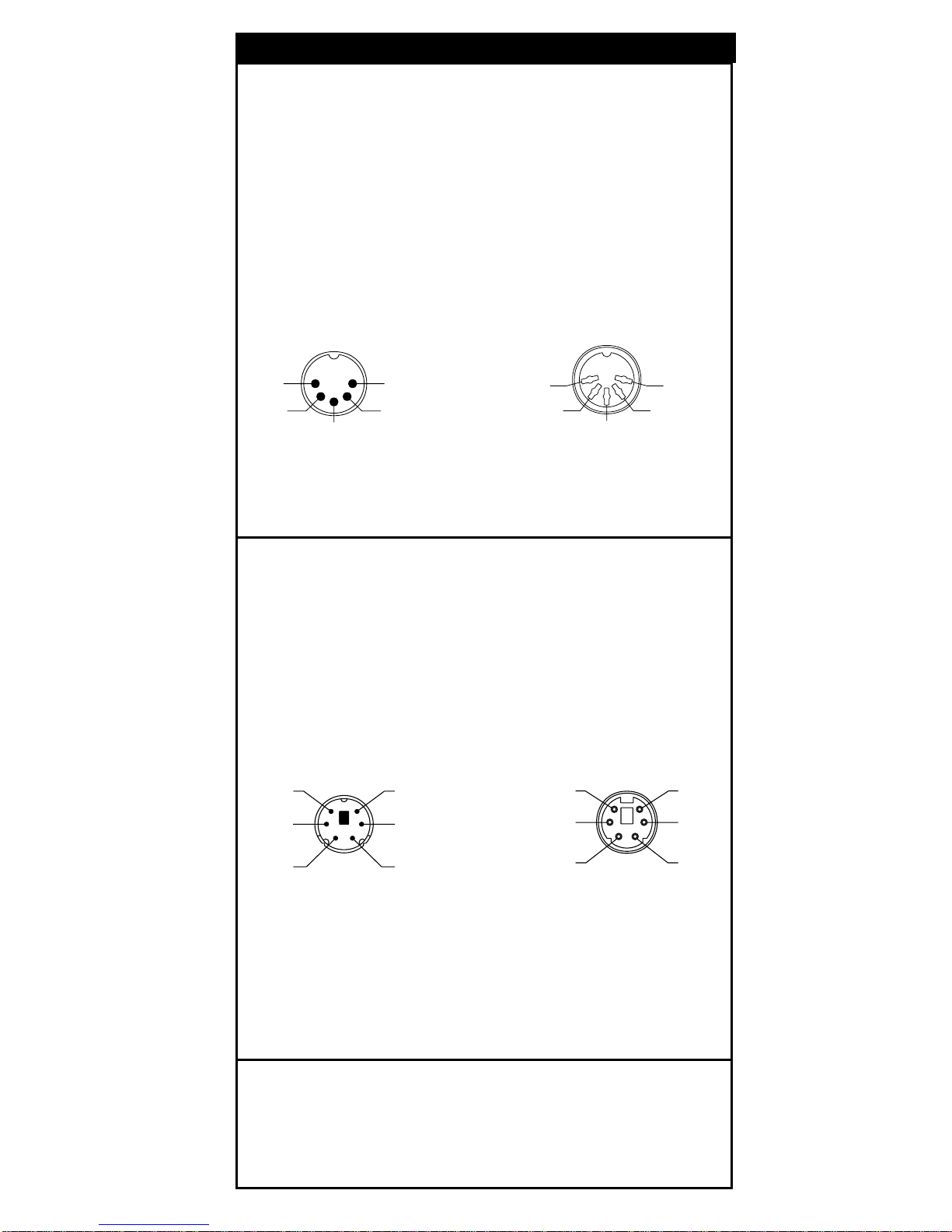
5
1. Keyboard Output
DIN 5 MALE DIN 5 FEMALE
Pin No. Function Pin No. Function
1 HOST CLK 1 KB CLK
2 HOST DAT A 2 KB DAT A
4 GND 4 GND
5 Vcc(+5V) 5 Vcc(+5V)
DIN 5 Male DIN 5 Female
Pin Assignment Pin Assign ment
MiniDIN 6 MALE MiniDIN 6 FEMALE
Pin No. Function Pin No. Function
1 HOST DAT A 1 KB DAT A
3 GND 3 GND
4 Vcc 4 Vcc
5 HOST CLK 5 KB CLK
MiniDIN 6 Male MiniDIN 6 Female
Pin Assignment Pin Assignment
Pin Assignments
4
5
3
2
1
5
4
1
2
3
3
1
5
4
2
6
3
1
5
4
2
6
Page 6
6
6
1
5
9
6
1
5
9
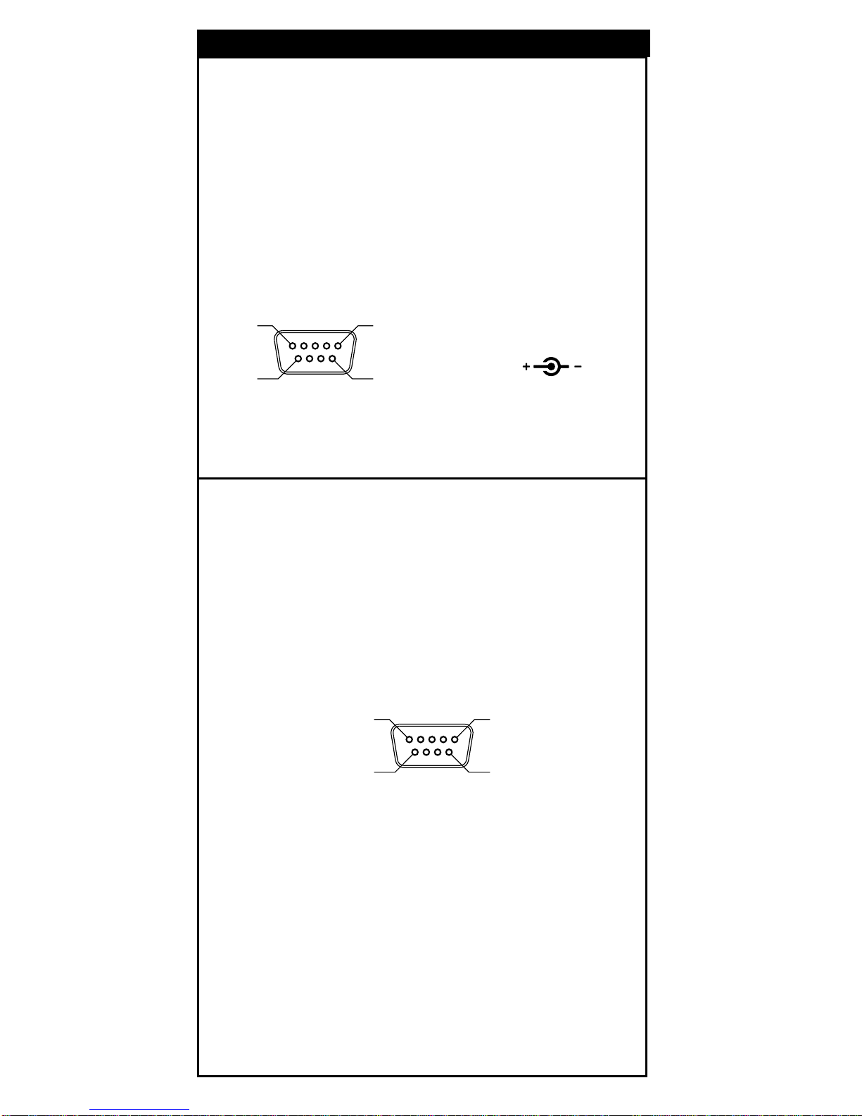
DB 9 Female Pin Assignment
2. RS-232 Output
DB 9 Female
Pin No. Function
2 TXD
3 RXD
5 GND
7 CTS
8 RTS
Power Lead Vcc +5V
DB 9 Female Pin Assignment M ale DC Jack
+5V GND
3. WAND Emulation Output
DB 9 Female
Pin No. Function
2DATA
7 GND
9 Vcc (+5V)
Pin Assignments
Page 7
7
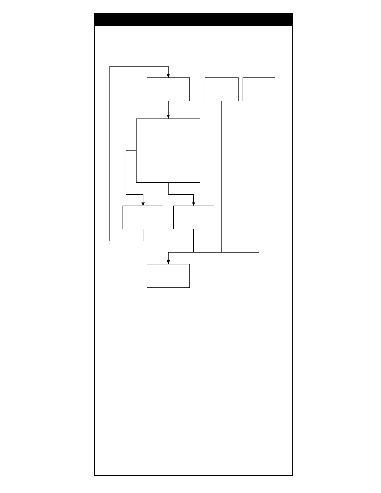
Setup Flow Chart
Loop of Programming
The philosophy of programming parameters has been
shown on the flow chart. Basically user should
1. Scan Start of Configuration.
2. Scan all necessary labels f or parameters that meet
applications.
3. Scan End of Configuration to end the programming.
4. To perma nently save the settings you programmed, just
scan label f or Save Parameters.
5. To go back to the Default Settings, just scan label f or Set
All Defaults.
Start
Configuration
Set All
Defaults
Recall
Parameters
Interface Selection
Input Port Selection
Communication
Parameters
Bar Codes Parameters
MSR Parameters
Misc. Parameters
etc.
End
Configuration
Save
Parameters
Abort
Configuration
Method of Progra mming
Page 8
8
Fa ctory Default Settings
The fa ctory default settings are shown with < > a nd bold in
the following sections. You can ma ke your own settings by
following the procedures in this ma nual. If you wa nt to save
the settings permanently , you should sca n the label of "Save
Parameters" on page 9, otherwise the settings will not be
saved after the decoder power is off, and all settings will go
back to previous settings.
By scanning "Set All Default" label, the settings will go ba ck
to the factory default settings.
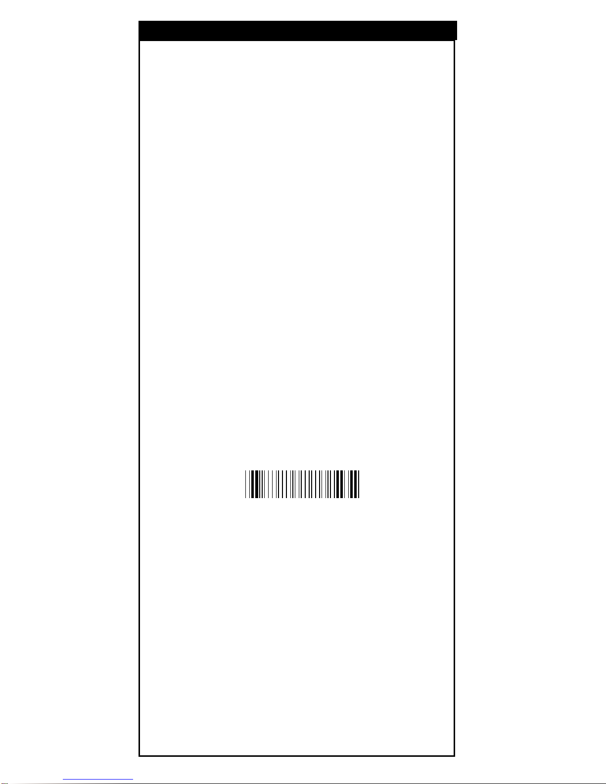
Download/Upload Settings
This decoder offers an easy way to config all parameters
from RS232 or PC keyboard interface. Just one click to
download or upload confiuration data instead of sca nning
bar codes in this menu.
Scan the Download/Upload bar code below to proceed
downloading or uploading.
Download/Upload
Method of Progra mming
%$ + / 7
Page 9
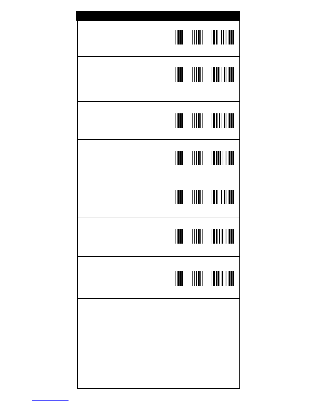
9
Save Parameters
Save the parameter settings
permanently.
Recall Stored
Parameters
Repla ce the current parameters
by which you had saved last time.
Set All Defaults
Set all the parameters to
the factory default settings.
Start Configuration
End Configuration
Abort Configuration
Terminate current
programming status.
Version Information
Display the decoder version
information a nd date code.
%$ + / 0
%$ + / 1
%$ + / 2
%$ + / 3
%$ + / 4
%$ + / 6
%$ + / 5
Setup Commands
Page 10
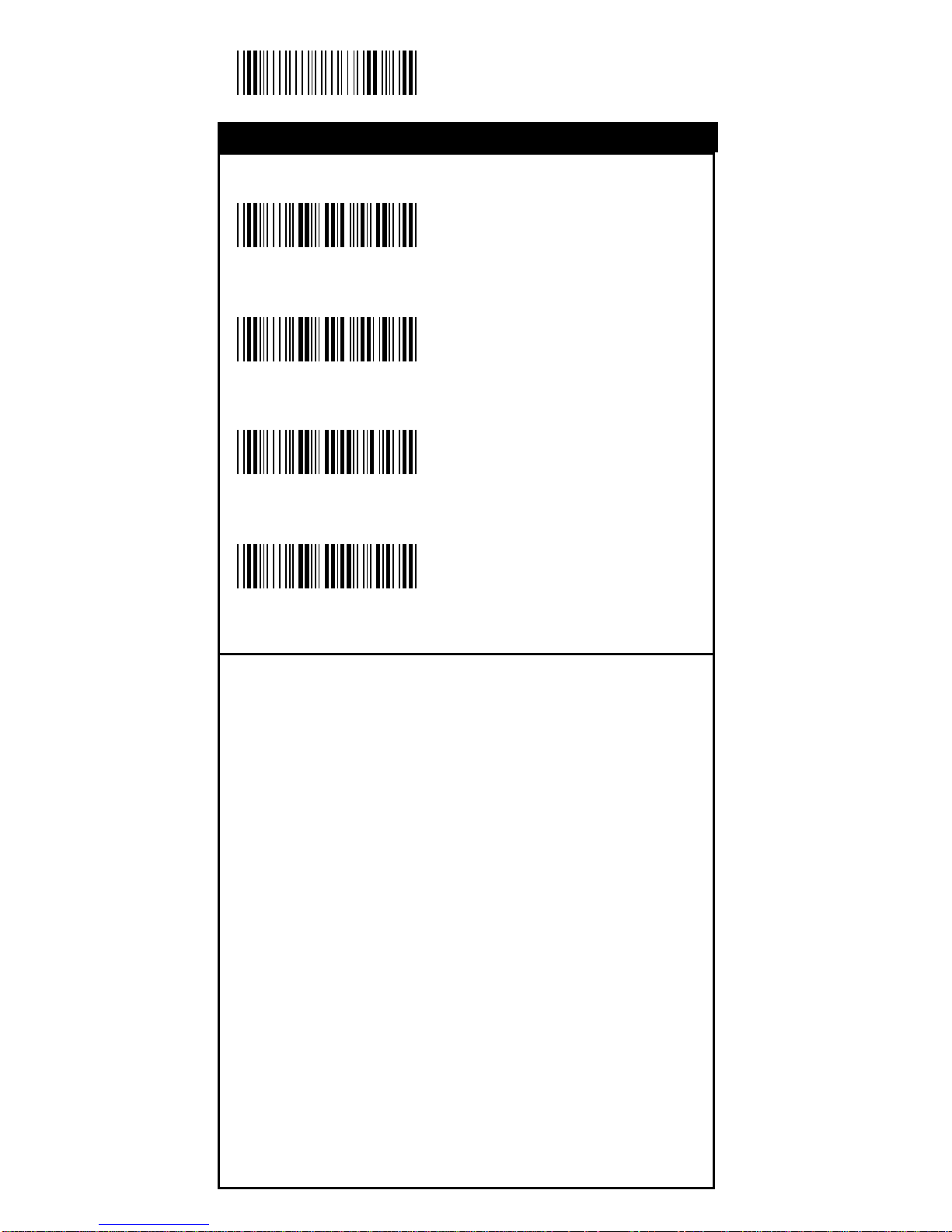
10
Start Configuration
<Keyboard/USB Mode>
RS232 Mode
WAND Emulation
OCIA Mode
%0 0 U 0
%0 0 U 8
%0 0 M 2
%0 0 M 4
Interface Selection
Interface
Page 11
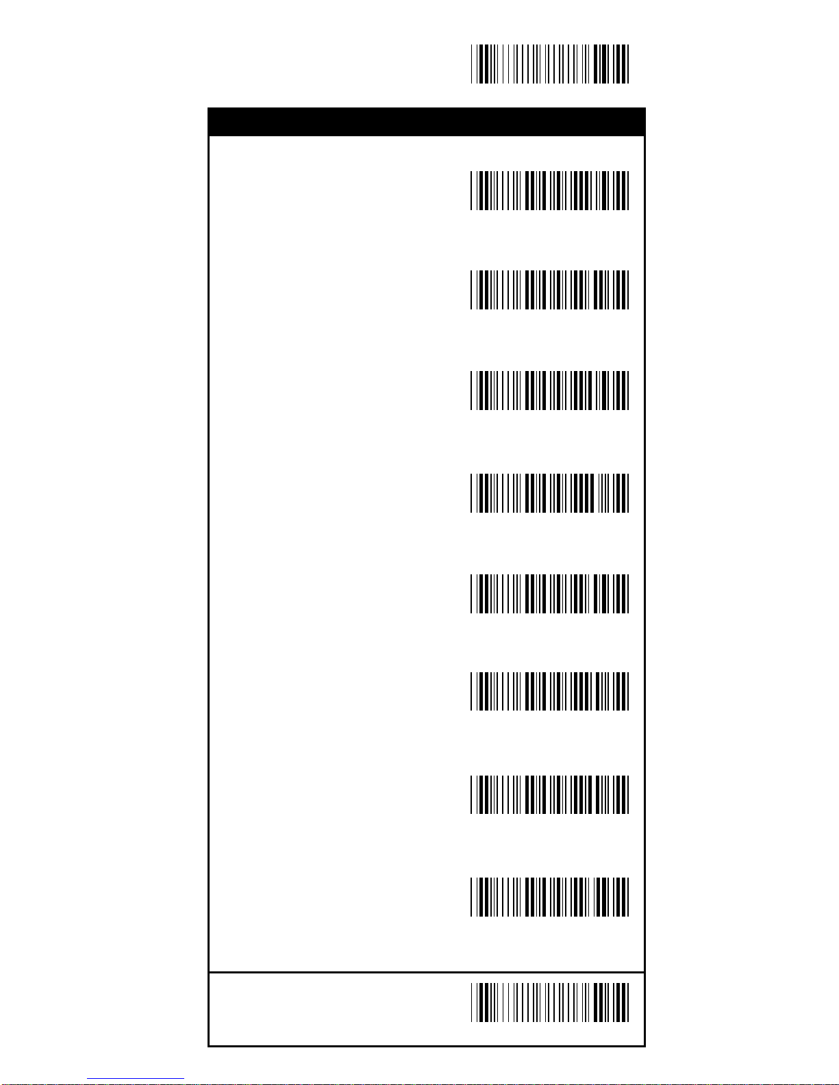
11
End Configuration
Save Configuration
<Good Read OFF>
Trigger ON/OFF
Continuous/Trigger OFF
Continuous/No Trigger
Flash
Testing
Reserved1
Reserved2
%0271
%0270
%0272
%0275
%0273
%0274
%0276
%0277
Reading Mode
Re ading Mode
Save Configuration
Page 12
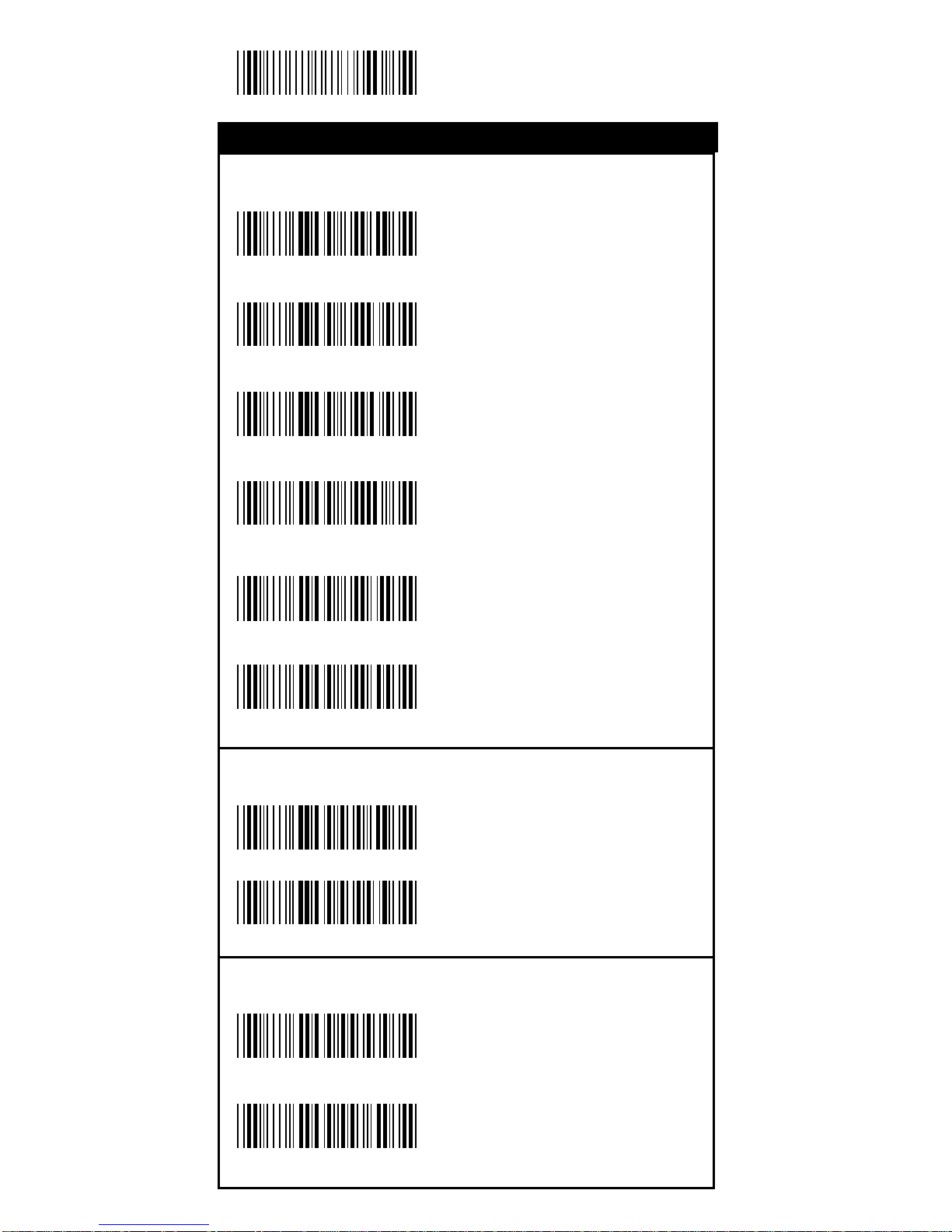
12
Start Configuration
Set Up BAUD Rate
600
1200
2400
4800
<9600>
19200
Set Up Data Bits
7 Data Bits
<8 Data Bits>
Set Up Stop Bits
<1 Bit>
2 Bits
%0 Y 8 0
%0 Y 8 8
%0 Y 7 0
%0 Y 7 1
%0 Y 7 2
%0 Y 7 3
%0 Y 7 7
%0 Y 7 4
%0 Y O8
%0 Y O0
RS-232 Communication Para meters
RS-232 Communication
Page 13
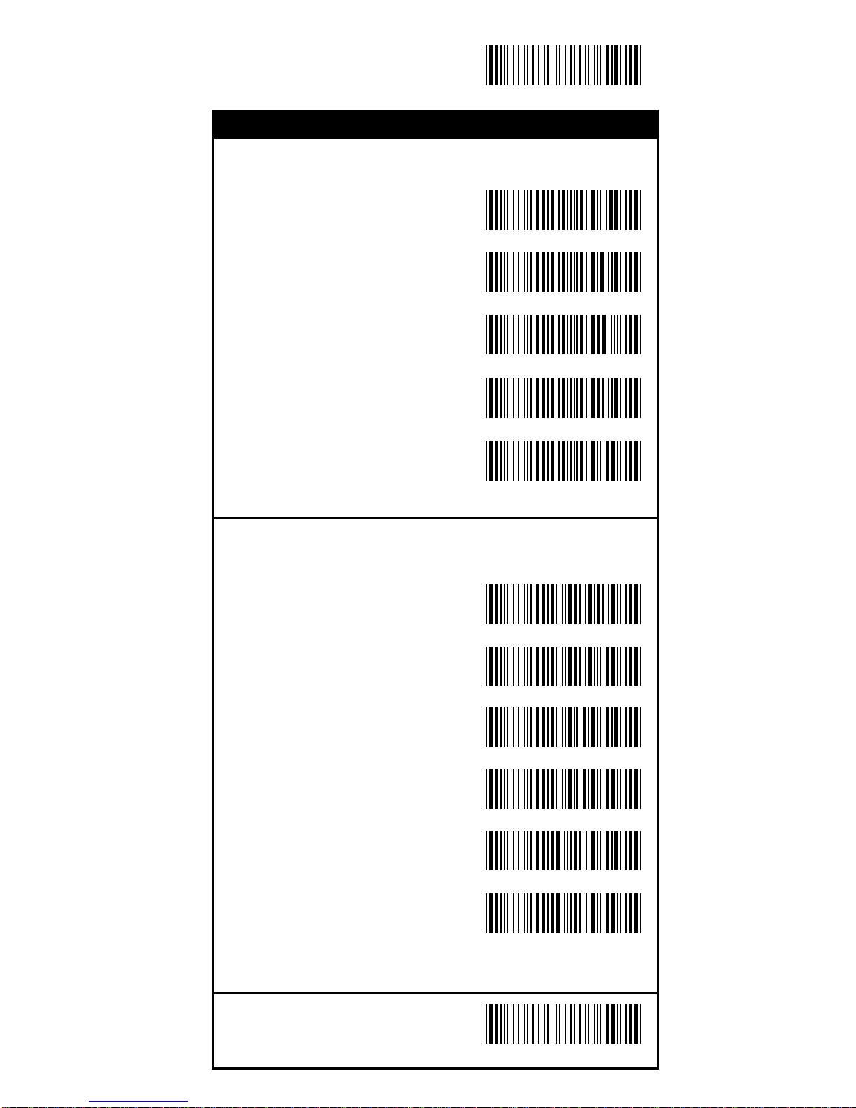
13
End Configuration
Save Configuration
Set Up Parity
<None>
Even
Odd
Mark
Space
Handsha king
RTS/CTS Enable
<RTS/CTS Disable>
ACK/NAK Enable
<ACK/NAK Disable>
XON/XOFF Enable
<XON/XOFF Disable>
%0 Y N 7
%0 Y N 2
%0 Y N 3
%0 Y N 1
%0 Y N 0
%0188
%0180
%0144
%0140
%0 3 K 4
%0 3 K 0
RS-232 Communication Para meters
RS-232 Communication
Page 14
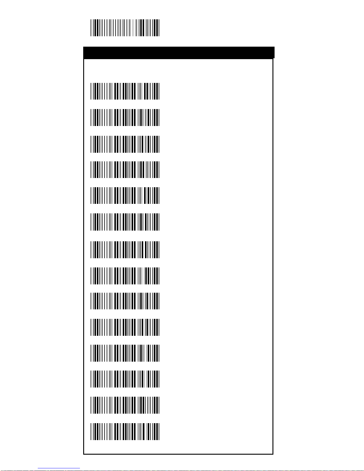
14
Start Configuration
T ermin al Type
<IBM PC/AT, PS/2>
IBM PC/XT
IBM PS/2 25, 30
NEC 9800
ADB
IBM 5550
IBM 122 Key (1)
IBM 102 Key
IBM 122 Key (2)
Reserved 1
Reserved 2
Reserved 3
Reserved 4
Reserved 5
%0ZF0
%0ZF1
%0ZF2
%0ZF3
%0ZF4
%0ZF5
%0ZF6
%0ZF7
%0ZF8
%0ZF9
%0ZFA
%0ZFB
%0ZFC
%0ZFD
Keyboard W edge Parameters
Keyboard Wedge
Page 15
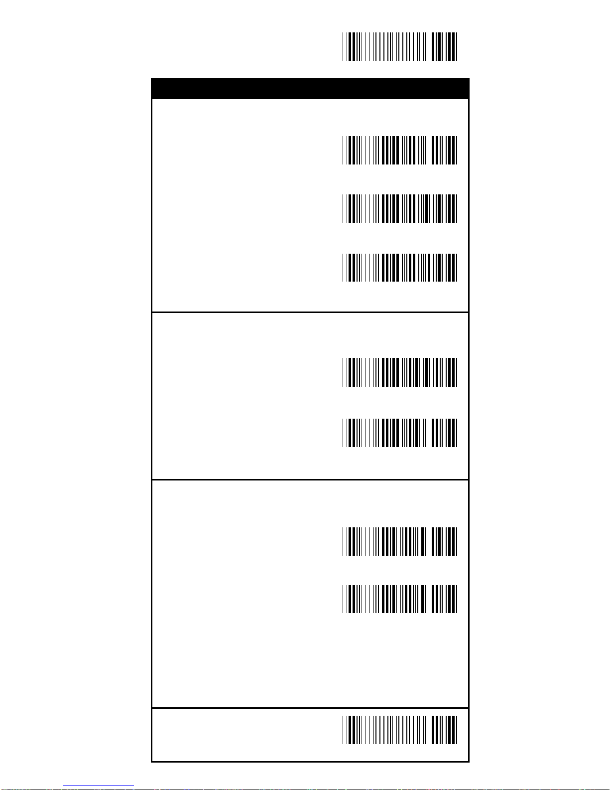
15
End Configuration
Save Configuration
Upper/Lower Ca s e
<No Change>
Upper Case
Lower Case
Send Character by ALT Method
Enable
<Disable>
Select Numerical Pad
ON
<OFF>
%0 3 O 8
%0 3 O 0
%0 1 K 4
%0 1 K 0
%0330
%0331
%0332
Keyboard W edge Parameters
Keyboard Wedge
Page 16
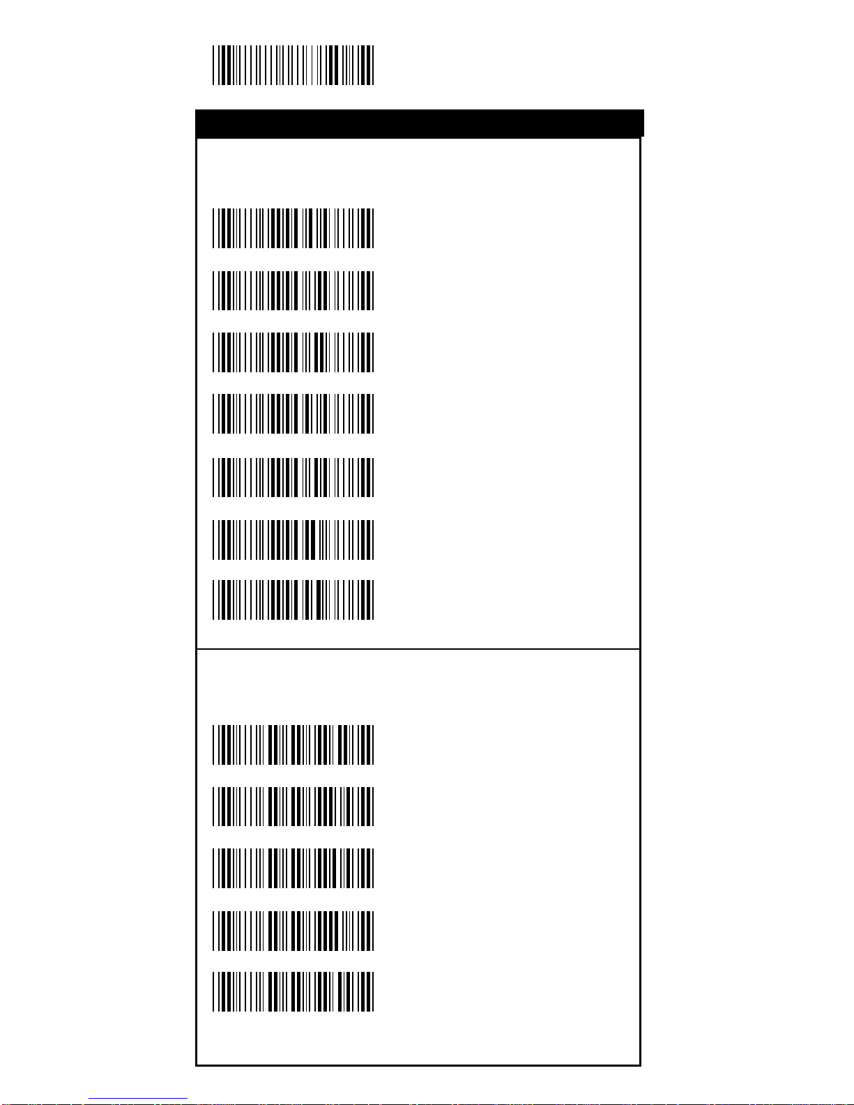
16
Start Configuration
Select Terminator
<CR+LF>
None
CR
LF
Space
HT(TAB)
STX-ETX
Time-out Between Characters
<0 ms>
5 ms
10 ms
25 ms
50 ms
%0070
%0071
%0072
%0073
%0074
%7 S 0 +
%7 S 2 +
%7 S 4 +
%7 S 5 +
%7 S 7 +
%7 S 1 +
%7 S 3 +
Output Characters Para meters
Output Para meters
Page 17
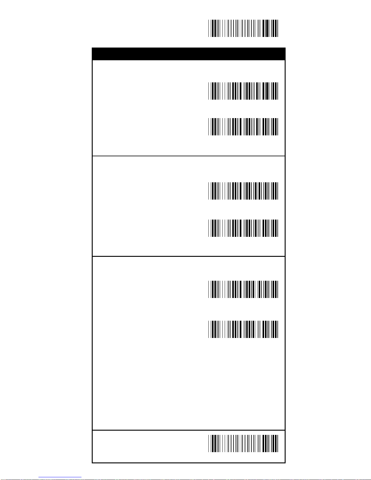
17
End Configuration
Save Configuration
TTL Level Re pre sentation
<Bar equals High>
Bar Equals Low
Sca n Speed Selection
<Fast>
Slow
Output Format Selection
<Output as Code 39>
Output as Code 39
Full ASCII
%0 2 K 4
%0 2 K 0
%0288
%0280
%0 2 O 8
%0 2 O 0
Wa nd Emulation
Wa nd Emulation
Page 18
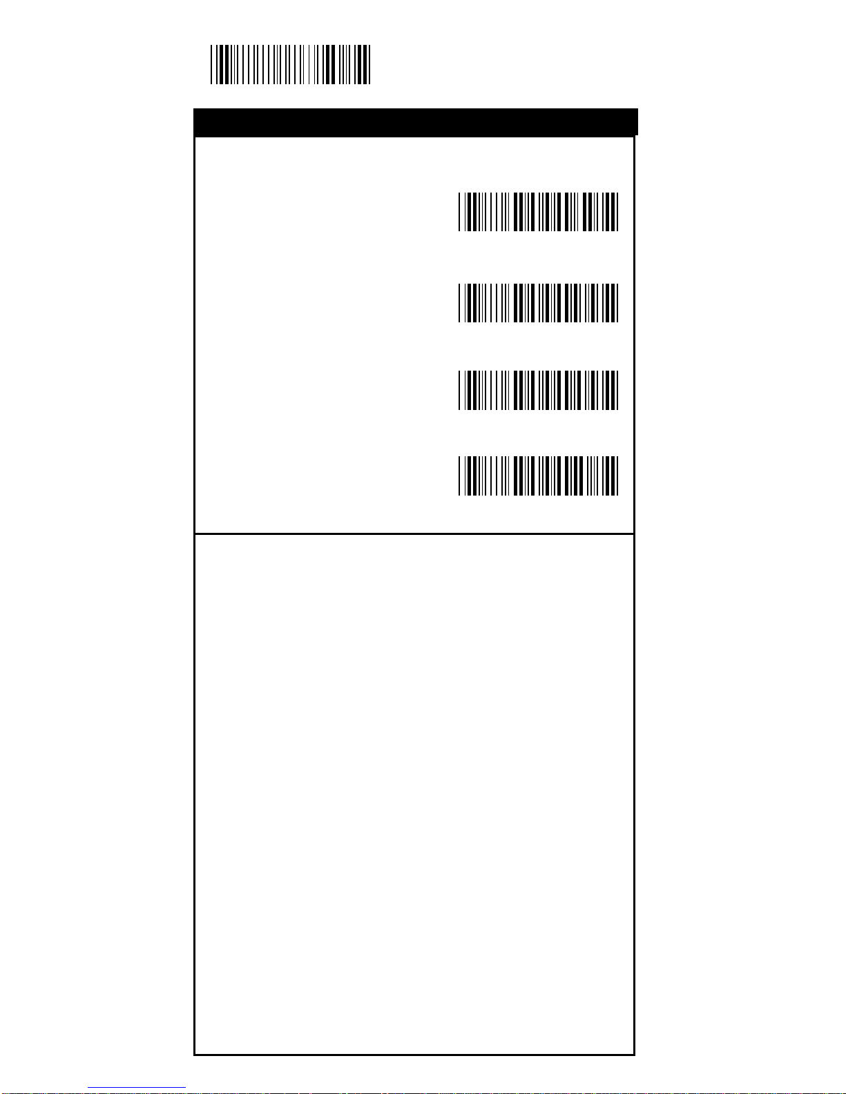
18
Start Configuration
OCIA Mode Parameters
<NCR 8 Bit Format>
NCR 9 Bit Fomat
Spectra-Physics
Nixdorf
OCIA Mode Parameters
%0 2 J 0
%0 2 J 1
%0 2 J 2
%0 2 J 3
OCIA Mode
Page 19
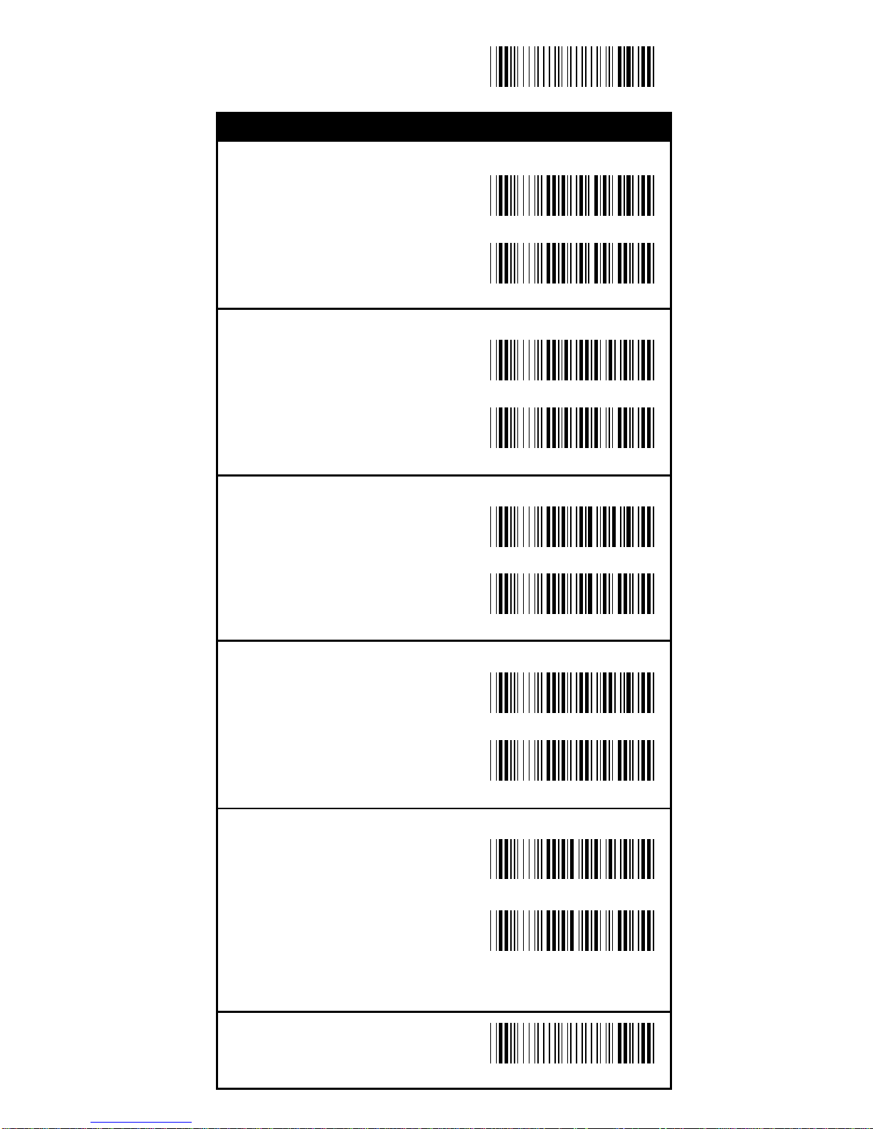
19
End Configuration
Save Configuration
UPC-A
<ON>
OFF
UPC-E
<ON>
OFF
EAN-13/JAN-13
<ON>
OFF
EAN-8/JAN-8
<ON>
OFF
CODE 39
<ON>
OFF
%0 A 4 4
%0 A 4 0
%0 B O8
%0 B O0
%0 A 2 2
%0 A 2 0
%0 A 1 1
%0 A 1 0
%0 E O8
%0 E O0
Bar Code Type Selection
Symbology
Page 20
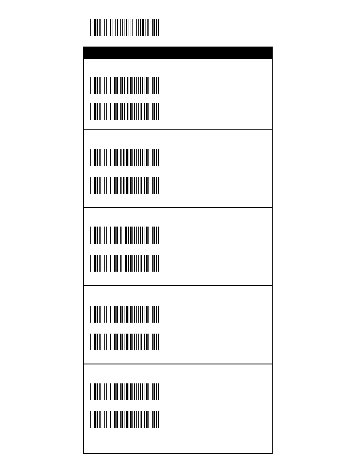
20
Start Configuration
CODE 128
<ON>
OFF
CODABAR/NW7
<ON>
OFF
Interleave 25
<ON>
OFF
Industrial 25
ON
<OFF>
Matrix 25
ON
<OFF>
Bar Code Type Selection
%0 GO8
%0 GO0
%0 H O 8
%0 H O 0
%0 I O 8
%0 I O 0
%0 F O 8
%0 F O 0
%0 J O 8
%0 J O 0
Symbology
Page 21
21
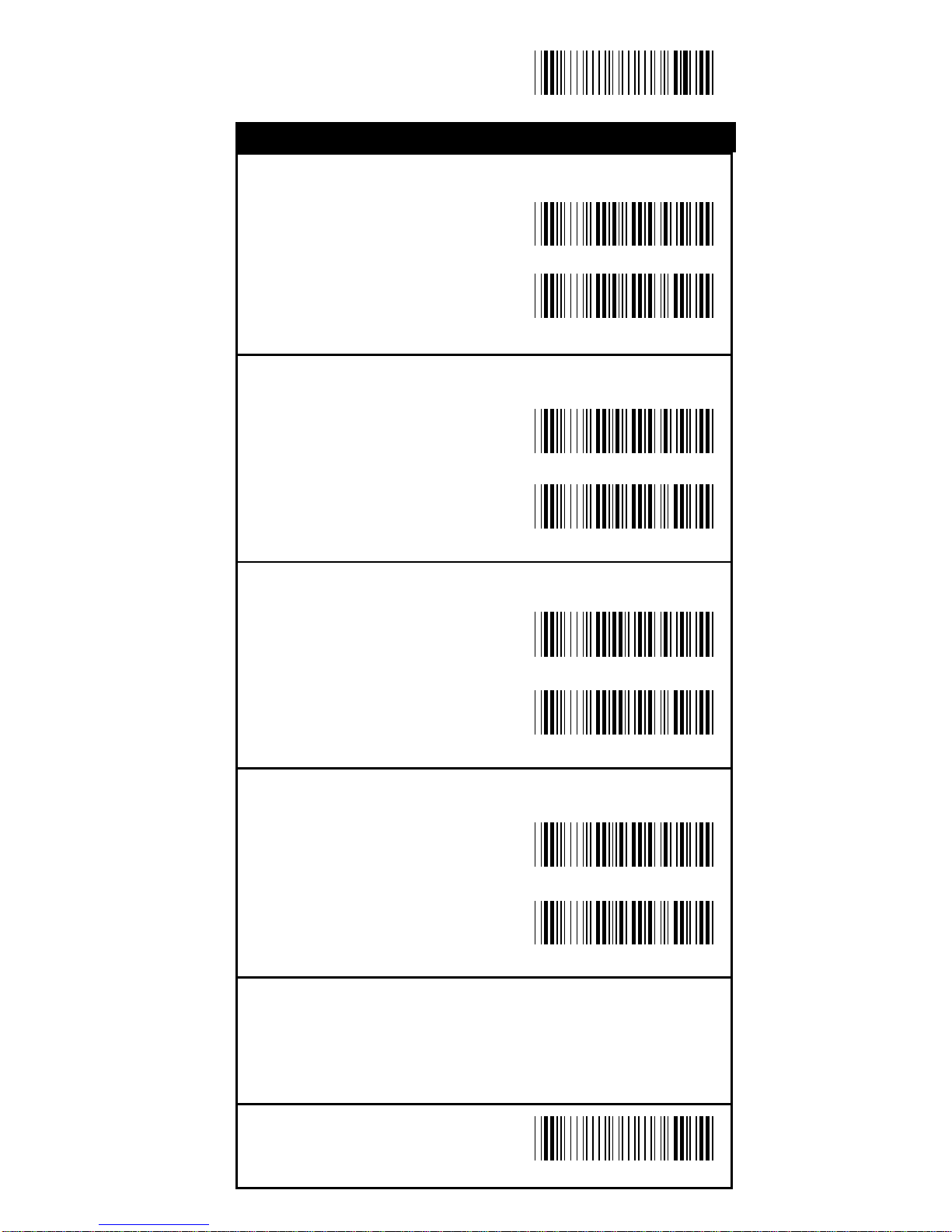
End Configuration
Save Configuration
CODE 93
ON
<OFF>
CODE 1 1
ON
<OFF>
China Postage
ON
<OFF>
MSI/PLESSEY
ON
<OFF>
Bar Code Type Selection
%0 K O8
%0 K O0
%0 L O 8
%0 L O 0
%0 M O 8
%0 M O 0
%0 N O 8
%0 N O 0
Symbology
Page 22
22
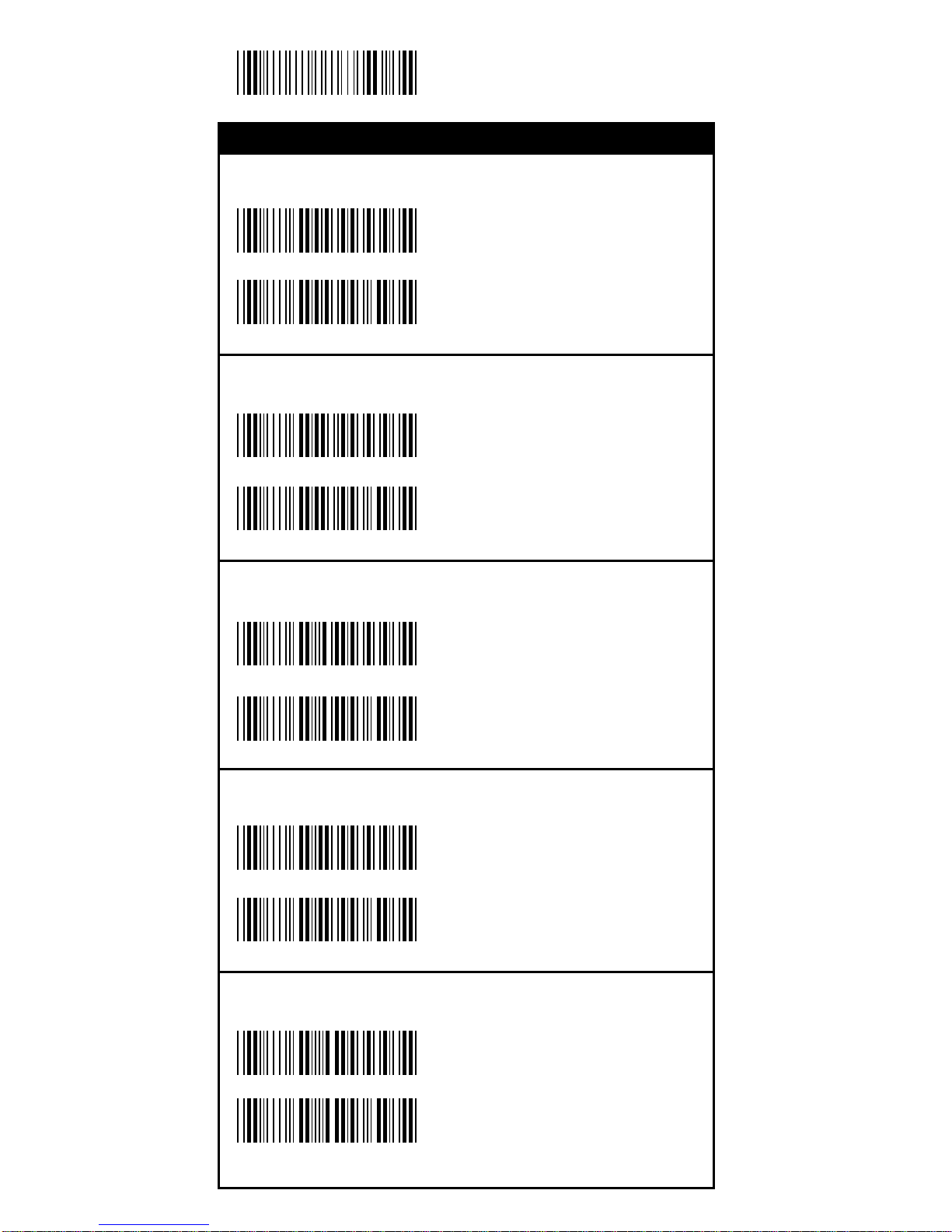
Start Configuration
BC412
ON
<OFF>
Reserved1
ON
<OFF>
Reserved2
ON
<OFF>
Reserved3
ON
<OFF>
Reserved4
ON
<OFF>
Bar Code Type Selection
Symbology
%0 OO8
%0 OO0
%0 C O 8
%0 C O 0
%0 D O 8
%0 D O 0
%0 P O8
%0 P O0
%0 QO8
%0 QO0
Page 23
23
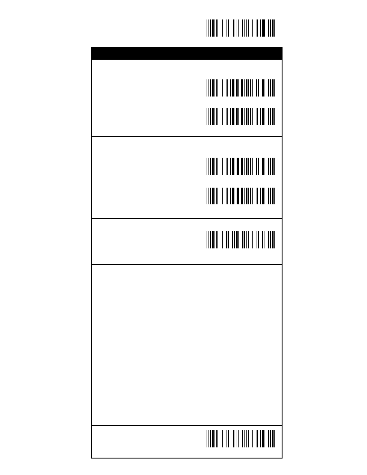
End Configuration
Save Configuration
Reserved5
ON
<OFF>
Reserved6
ON
<OFF>
Select All Bar Codes
Bar Code Type Selection
Symbology
%1 A / +
%0 R O 8
%0 R O 0
%0 S O8
%0 S O0
Page 24
24
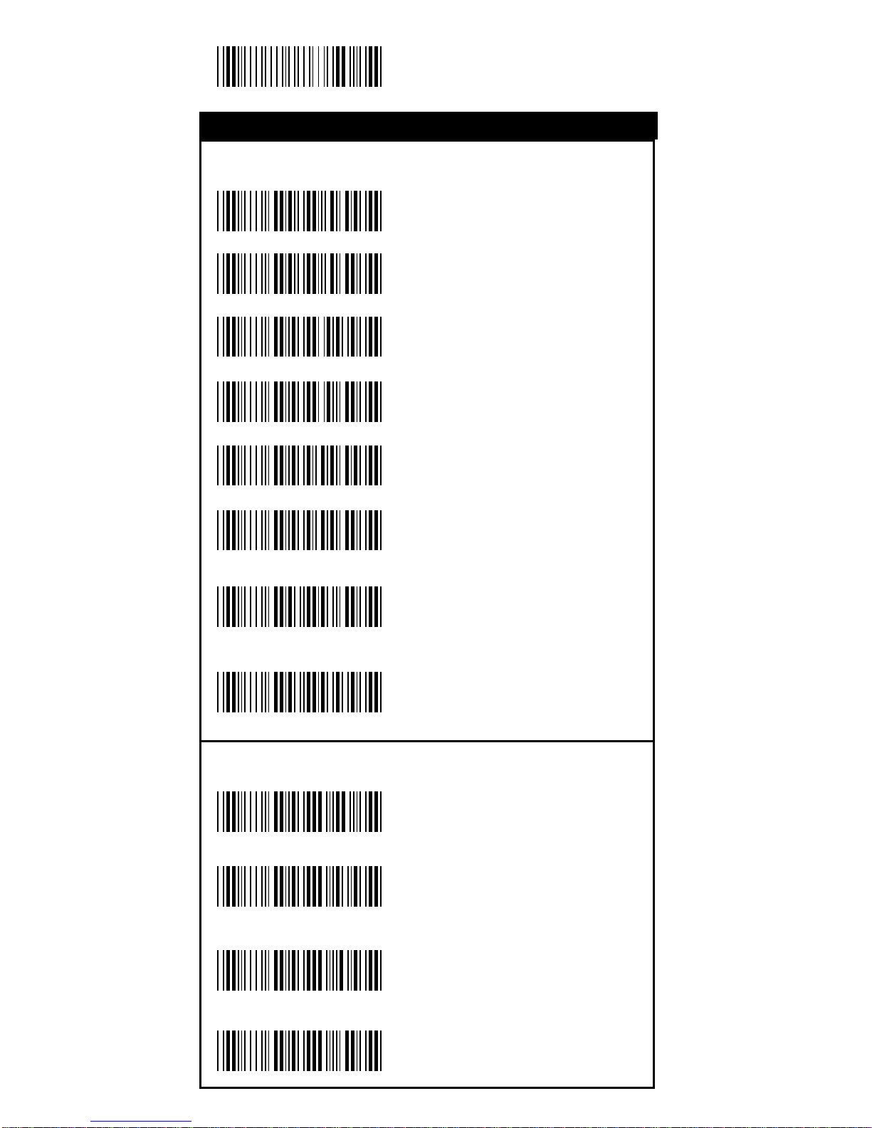
Start Configuration
Rea ding Type
UPCA=EAN13 ON
UPCA=EAN13<OFF>
ISBN Enable
ISBN <Disable>
ISSN Enable
ISSN <Disable>
Decode with
Supplementals
<Autodiscriminate
Supplementals>
Supplementals Set Up
<Not Transmit>
Transmit 2 Code
Transmit 5 Code
Tra nsmit 2&5 Code
%0AK4
%0AK0
%0 B 8 8
%0 B 8 0
%0 B 4 4
%0 B 4 0
%0 B 3 3
%0 B 3 1
%0 B 3 2
%0 B 3 0
%0 1 O 0
%0 1 O 8
UPC/EAN/JAN
Symbology
Page 25
25
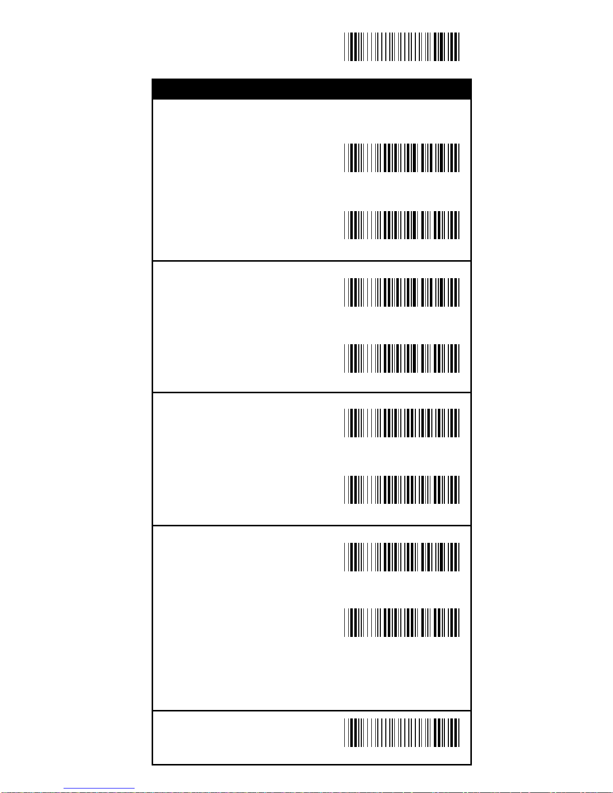
End Configuration
Save Configuration
Check Digit Transmission
UPC-A Check Digit
Transmission <ON>
OFF
UPC-E Check Digit
Transmission <ON>
OFF
EAN-8 Check Digit
Transmission <ON>
OFF
EAN-13 Check Digit
Transmission <ON>
OFF
%0 A I 2
%0 A I 0
%0 B I 2
%0 B I 0
%0 A H 1
%0 A H 0
%0 A 8 8
%0 A 8 0
UPC/EAN/JAN
Symbology
Page 26
26
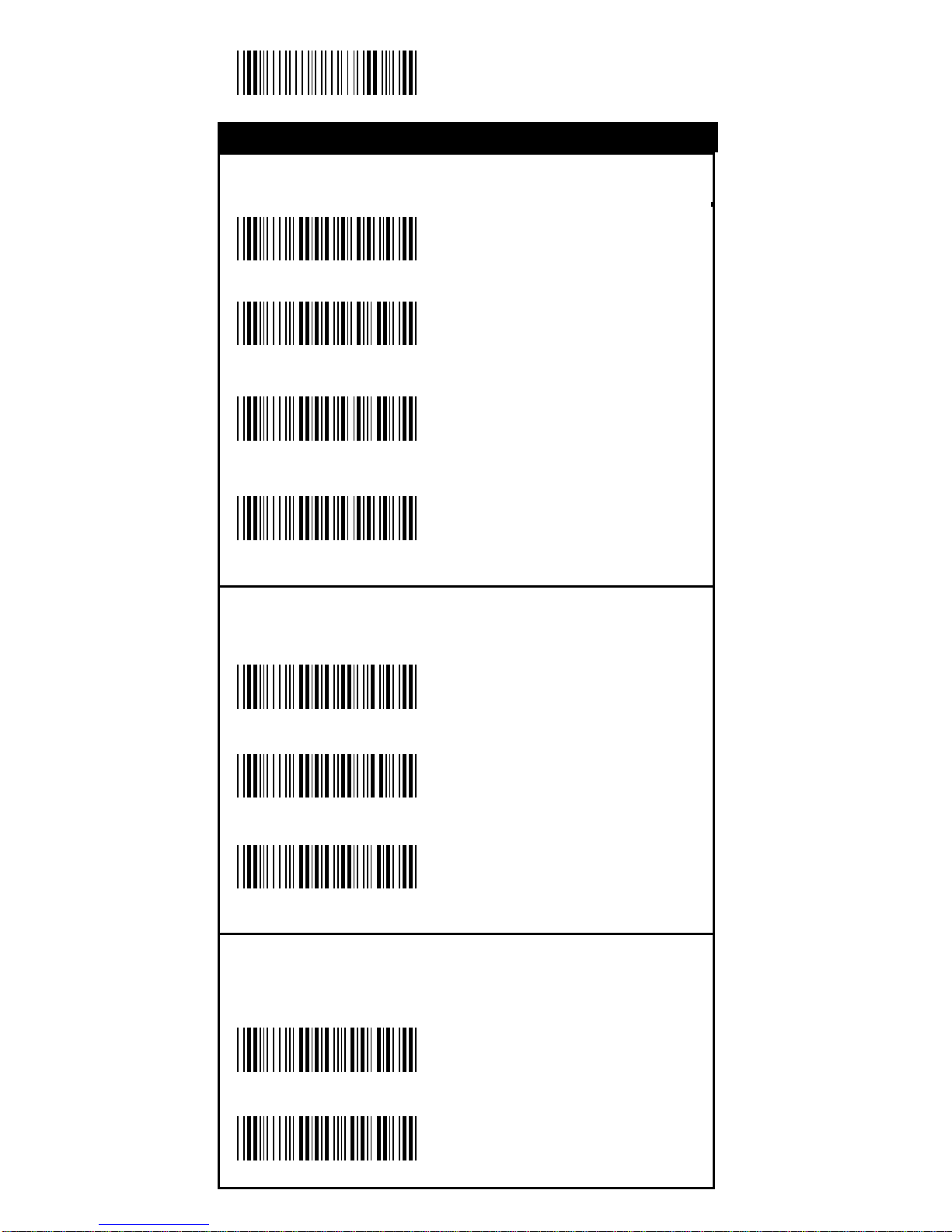
Start Configuration
T ype of Code
<Standard>
Full ASCII
Italian Pharma cy/Code
32<OFF>
Italian Pharma cy/
Code 32 ON
Check Digit Transmission
<Do Not Calculate
Check Digit>
Calculate Check Digit
&T ransmit
Calculate Check Digit
& Not Tra nsmit
Output Start/Stop Character
Enable
<Disable>
%0 E H 1
%0 E H 0
%0 E 8 8
%0 E 8 0
%0 E M2
%0 E M6
%0 E M4
%0 E 4 4
%0 E 4 0
Code 39
Symbology
Page 27
27
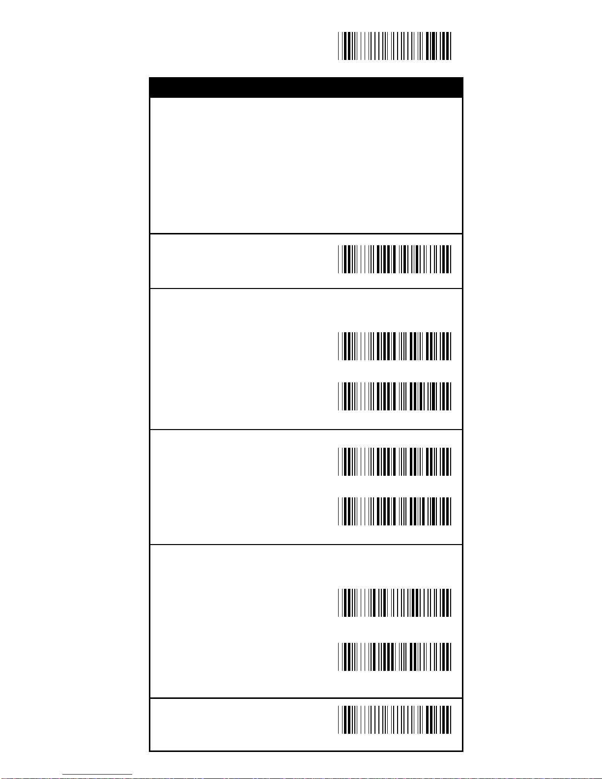
End Configuration
Save Configuration
Set Up Code Length
T o set the fixed length:
1. Sca n the "Begin" label of the de sired set.
2. Go to the Decimal Value Tabl es in Appendix A, scan
label(s) that represents the length to be read.
3. Sca n the "Complete" label of the desired set.
Repeat the steps 1 - 3 to set additional lengths.
<Variable>
Fix Length (2 Sets Availa ble)
1st Set Begin
(Then scan value in
Appendix A)
1st Set Complete
2nd Set Begin
(Then scan value in
Appendix A)
2nd Set Complete
Minimum Length
Begin(Then scan value
in Appendix A)
Complete
%4 E 1 +
%4 E 0 0
%4 E 0 1
%4 E 0 0
%4 E 0 2
%2 C 0 +
%2 + - /
Code 39
Symbology
Page 28
28
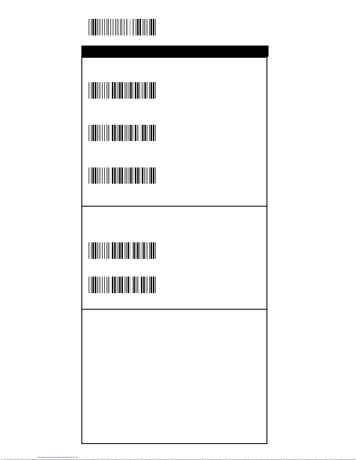
Start Configuration
Check Digit Transmission
Do Not Calculate
Check Digit
Calculate Check
Digit & Transmit
<Calculate Check
Digit & Not Transmit>
Append F NC2
ON
<OFF>
%0 F N 7
%0 F N 5
%0 F 8 8
%0 F 8 0
%0 F N 1
Code 128
Symbology
Page 29
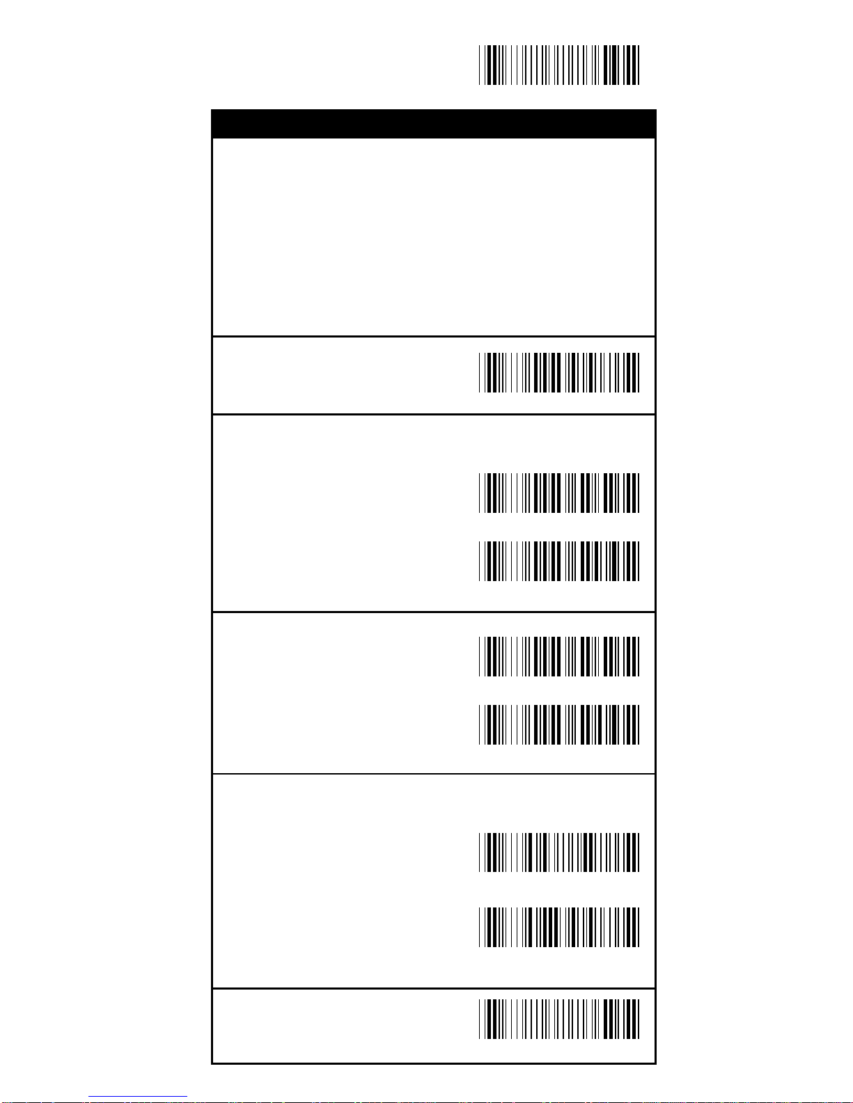
29
End Configuration
Save Configuration
Set Up Code Length
T o set the fixed length:
1. Sca n the "Begin" label of the de sired set.
2. Go to the Decimal Value Tabl es in Appendix A, scan
label(s) that represents the length to be read.
3. Sca n the "Complete" label of the desired set.
Repeat the steps 1 - 3 to set additional lengths.
<Variable>
Fix Length (2 Sets Availa ble)
1st Set Begin
(Then scan value in
Appendix A)
1st Set Complete
2nd Set Begin
(Then scan value in
Appendix A)
2nd Set Complete
Minimum Length
Begin(Then scan value
in Appendix A)
Complete
%4 F 1 +
%4 F 0 0
%4 F 0 1
%4 F 0 0
%4 F 0 2
%2 + - /
Code 128
Symbology
%2 C 1 +
Page 30
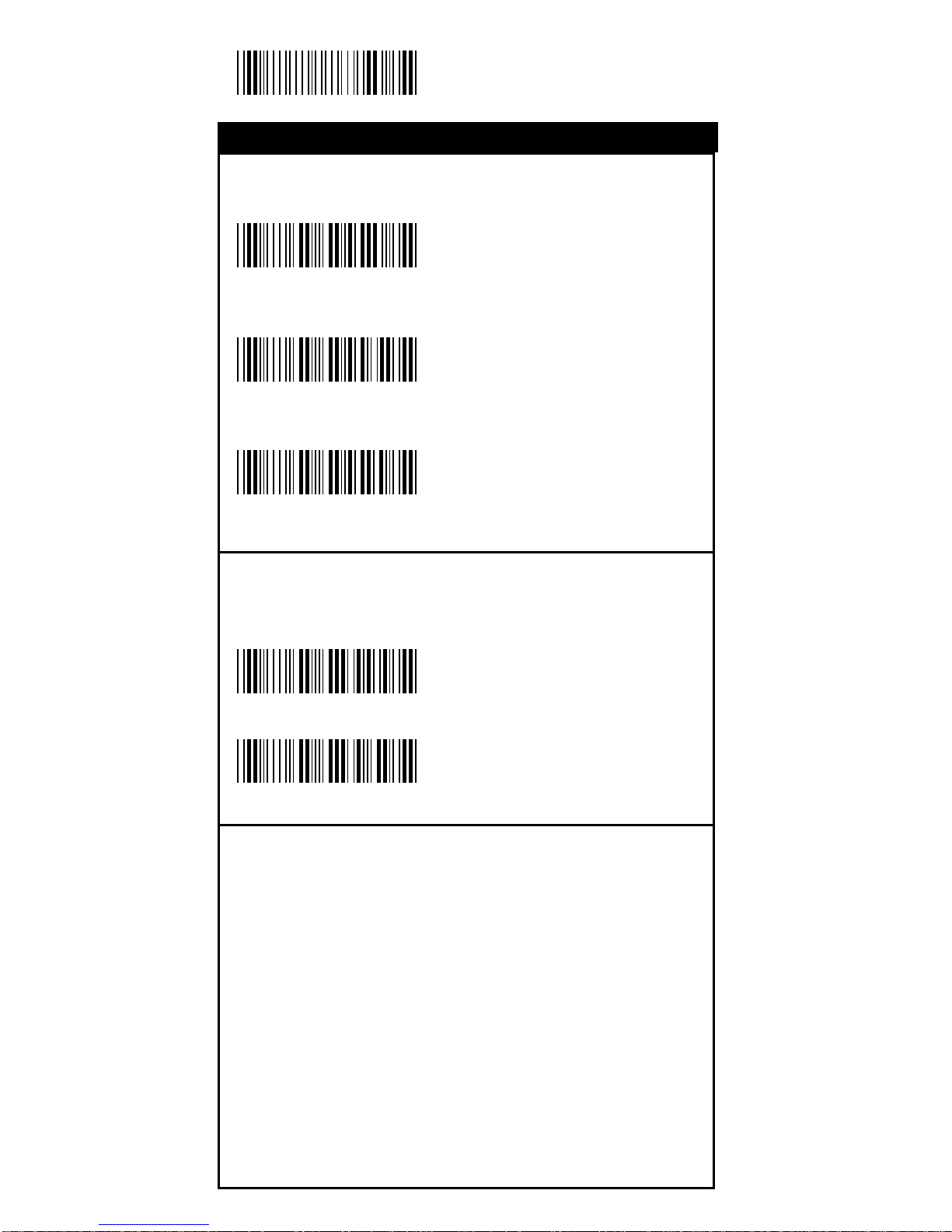
30
Start Configuration
Check Digit Transmission
<Do Not Calculate
Check Digit>
Calculate Check
Digit & Transmit
Calculate Check
Digit & Not T ransmit
Set Up Number of Character
<Even>
Odd
%0 G N 3
%0 G N 7
%0 G N 5
%0 G 8 8
%0 G 8 0
Interleave 25
Symbology
Page 31
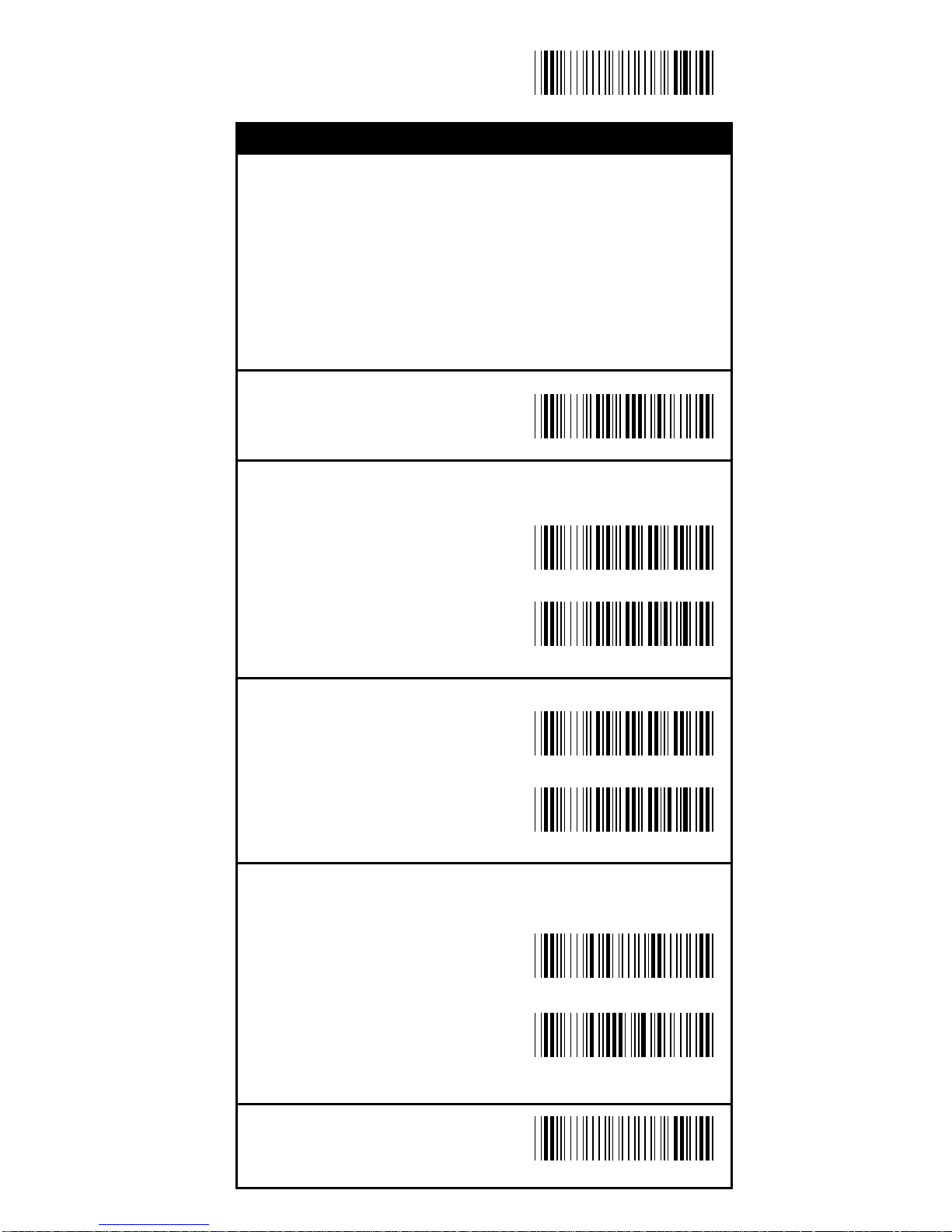
31
End Configuration
Save Configuration
Set Up Code Length
T o set the fixed length:
1. Sca n the "Begin" label of the de sired set.
2. Go to the Decimal Value Tabl es in Appendix A, scan
label(s) that represents the length to be read.
3. Sca n the "Complete" label of the desired set.
Repeat the steps 1 - 3 to set additional lengths.
<Variable>
Fix Length (2 Sets Availa ble)
1st Set Begin
(Then scan value in
Appendix A)
1st Set Complete
2nd Set Begin
(Then scan value in
Appendix A)
2nd Set Complete
Minimum Length
Begin(Then scan value
in Appendix A)
Complete
%4 G 1 +
%4 G 0 0
%4 G 0 1
%4 G 0 0
%4 G 0 2
%2 + - /
%2 C 2 +
Interleave 25
Symbology
Page 32
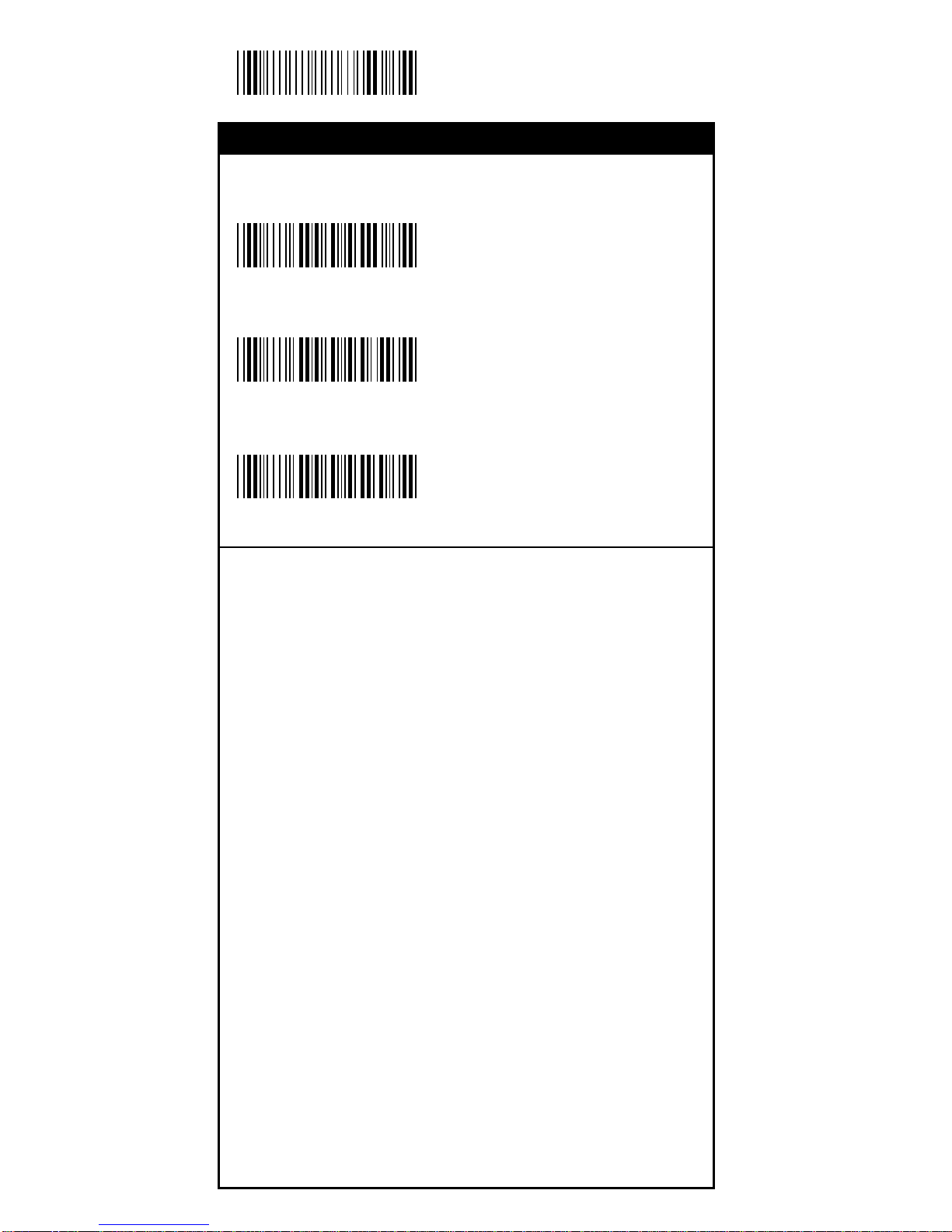
32
Start Configuration
Check Digit Transmission
<Do Not Calculate
Check Digit>
Calculate Check
Digit & Transmit
Calculate Check
Digit & Not T ransmit
%0 HN3
%0 HN7
%0 HN5
Industrial 25
Symbology
Page 33
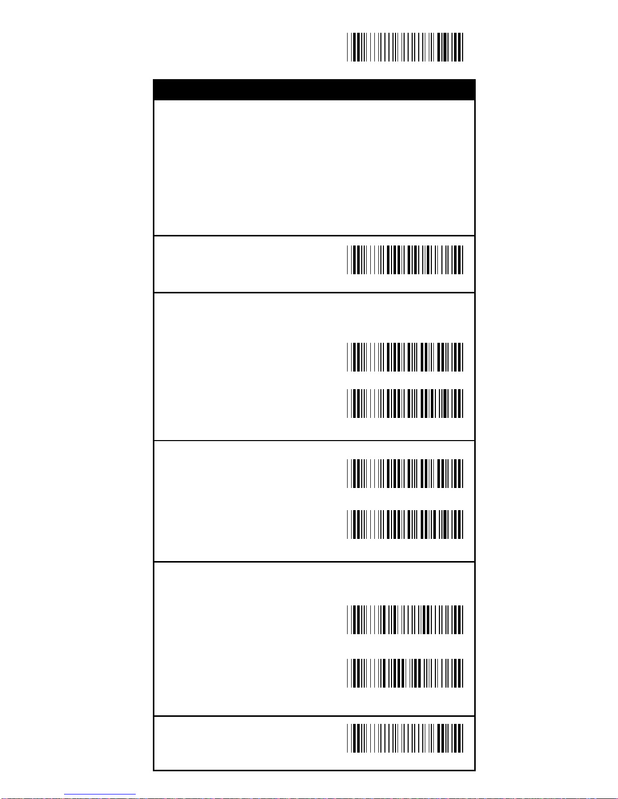
33
End Configuration
Save Configuration
Set Up Code Length
T o set the fixed length:
1. Sca n the "Begin" label of the de sired set.
2. Go to the Decimal Value Tabl es in Appendix A, scan
label(s) that represents the length to be read.
3. Sca n the "Complete" label of the desired set.
Repeat the steps 1 - 3 to set additional lengths.
<Variable>
Fix Length (2 Sets Availa ble)
1st Set Begin
(Then scan value in
Appendix A)
1st Set Complete
2nd Set Begin
(Then scan value in
Appendix A)
2nd Set Complete
Minimum Length
Begin(Then scan value
in Appendix A)
Complete
%4 H 1 +
%4 H 0 0
%4 H 0 0
%4 H 0 1
%4 H 0 2
%2 + - /
%2 C 3 +
Industrial 25
Symbology
Page 34
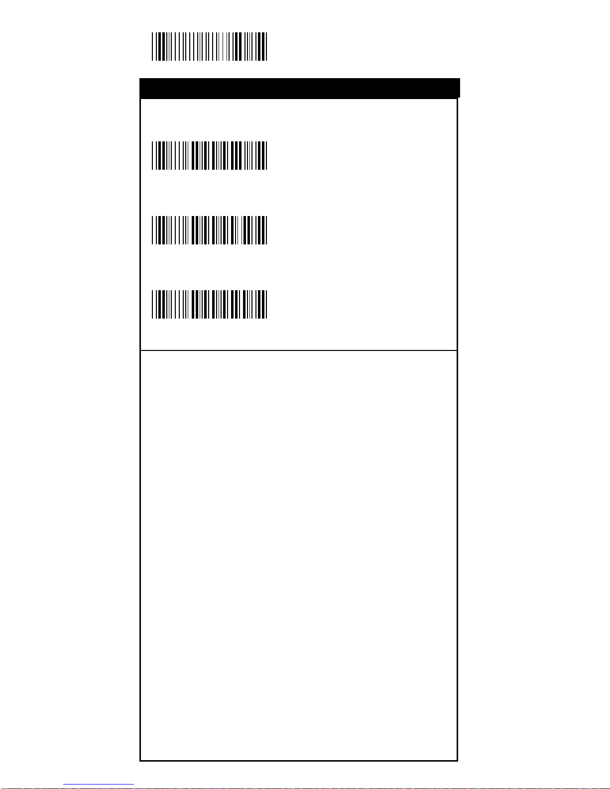
34
Start Configuration
Check Digit Transmission
<Do Not Calculate
Check Digit>
Calculate Check
Digit & Transmit
Calculate Check
Digit & Not T ransmit
%0 I N 3
%0 I N 7
%0 I N 5
Matrix 25
Symbology
Page 35
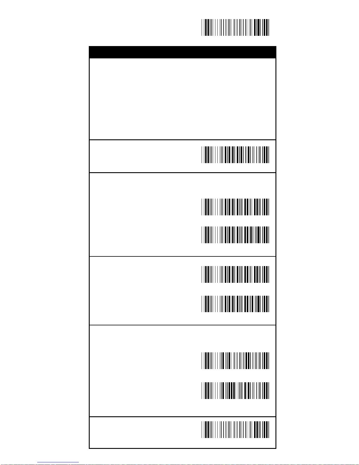
35
End Configuration
Save Configuration
Set Up Code Length
T o set the fixed length:
1. Sca n the "Begin" label of the de sired set.
2. Go to the Decimal Value Tabl es in Appendix A, scan
label(s) that represents the length to be read.
3. Sca n the "Complete" label of the desired set.
Repeat the steps 1 - 3 to set additional lengths.
<Variable>
Fix Length (2 Sets Availa ble)
1st Set Begin
(Then scan value in
Appendix A)
1st Set Complete
2nd Set Begin
(Then scan value in
Appendix A)
2nd Set Complete
Minimum Length
Begin(Then scan value
in Appendix A)
Complete
%4 I 1 +
%4 I 0 0
%4 I 0 0
%4 I 0 1
%4 I 0 2
%2 + - /
%2 C 4 +
Matrix 25
Symbology
Page 36
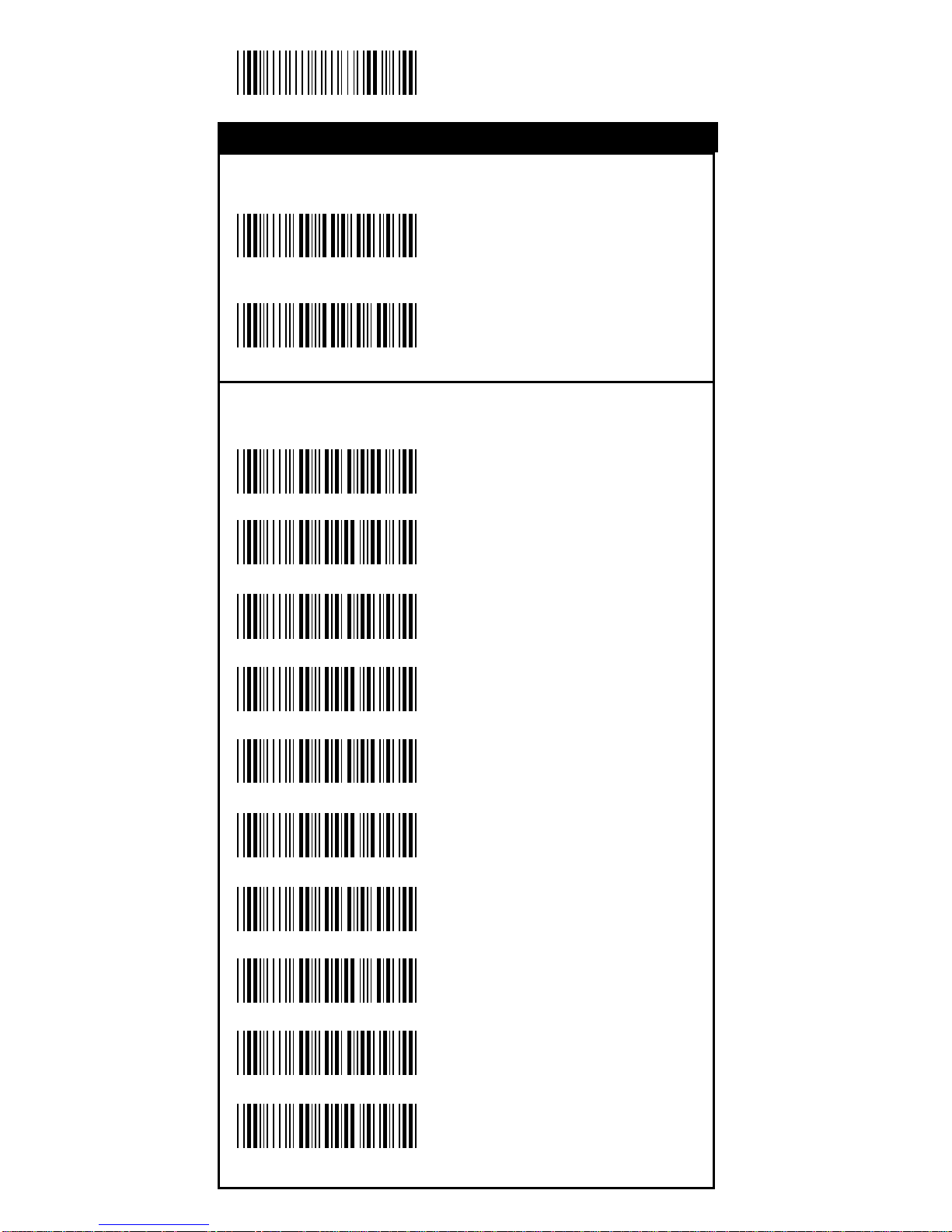
36
Start Configuration
Set Up Start/Stop Characters Upon Tra nsmission
ON
<OFF>
T ransmission Type of Start/Stop
<A/B/C/D> <Start>
<A/B/C/D> <Stop>
A Start
A Stop
B Start
B Stop
C Start
C Stop
D Start
D Stop
%0 J H 1
%0 J H 0
%0 4 V F
%0 4 F F
%0 4 V 1
%0 4 F 1
%0 4 V 2
%0 4 F 2
%0 4 V 4
%0 4 F 4
%0 4 V 8
%0 4 F 8
CODABAR/NW7
Symbology
Page 37
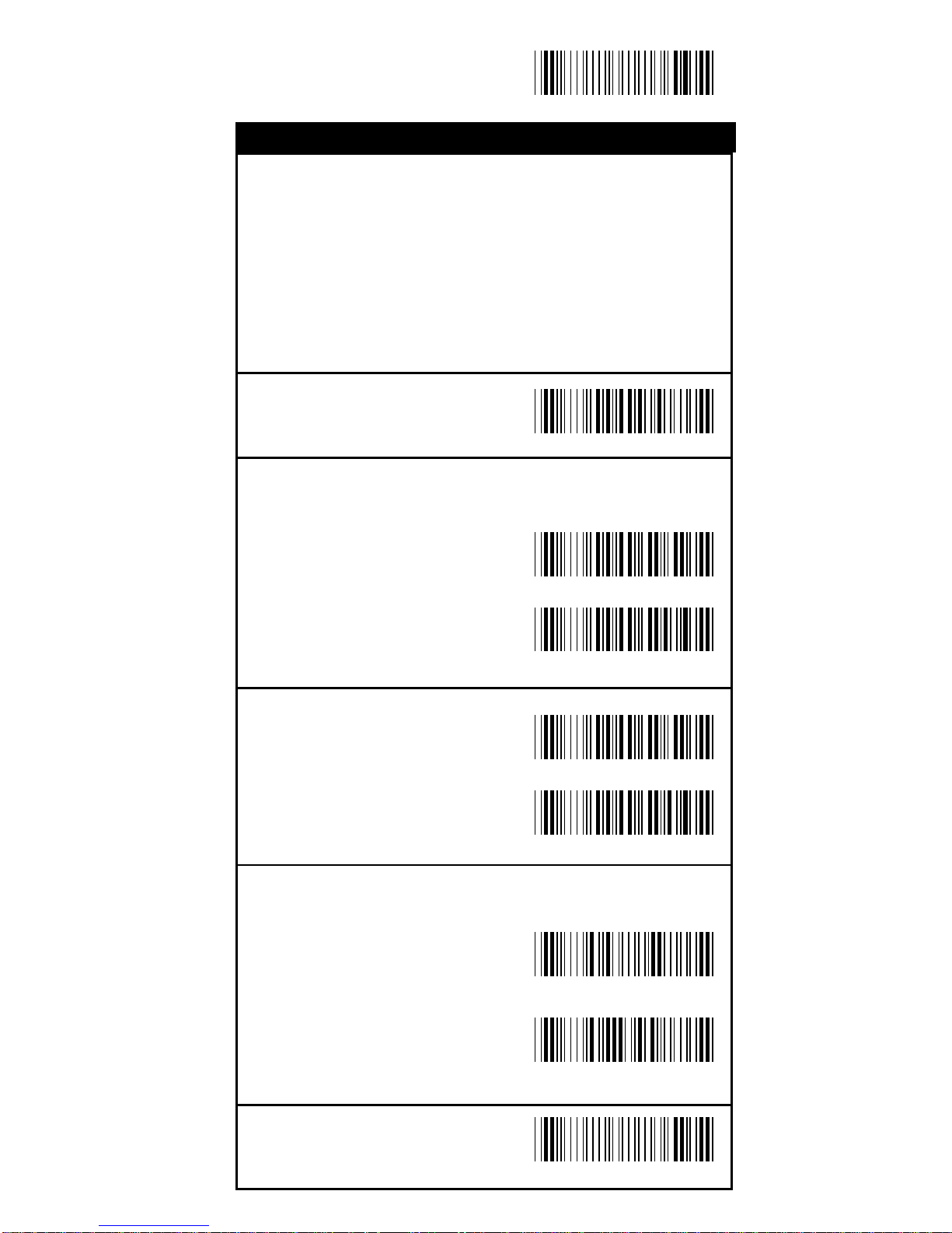
37
End Configuration
Save Configuration
Set Up Code Length
T o set the fixed length:
1. Sca n the "Begin" label of the de sired set.
2. Go to the Decimal Value Tabl es in Appendix A, scan
label(s) that represents the length to be read.
3. Sca n the "Complete" label of the desired set.
Repeat the steps 1 - 3 to set additional lengths.
<Variable>
Fix Length (2 Sets Availa ble)
1st Set Begin
(Then scan value in
Appendix A)
1st Set Complete
2nd Set Begin
(Then scan value in
Appendix A)
2nd Set Complete
Minimum Length
Begin(Then scan value
in Appendix A)
Complete
%4 J 1 +
%4 J 0 0
%4 J 0 0
%4 J 0 1
%4 J 0 2
%2 + - /
%2 C 5 +
CODABAR/NW7
Symbology
Page 38
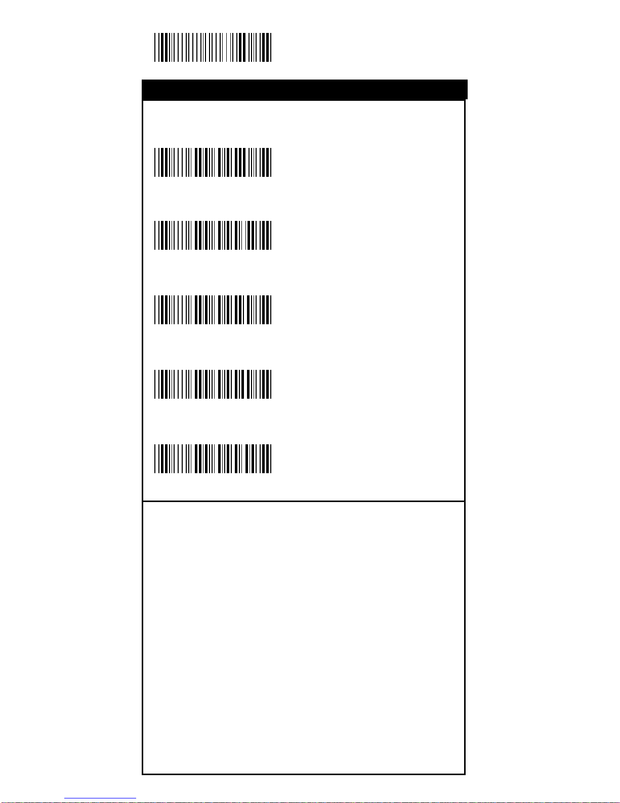
38
Start Configuration
Check Digit Transmission
<Do Not Calculate
Check Digit>
Calculate Check 1
Digit & Transmit
Calculate Check 1 Digit
& Not Tra nsmit
Calculate Check 2
Digits & Transmit
Calculate Check 2
Digits & Not T ransmit
%0 K N 3
%0 K N 7
%0 K N 5
%0 K N 6
%0 K N 4
Code 93
Symbology
Page 39
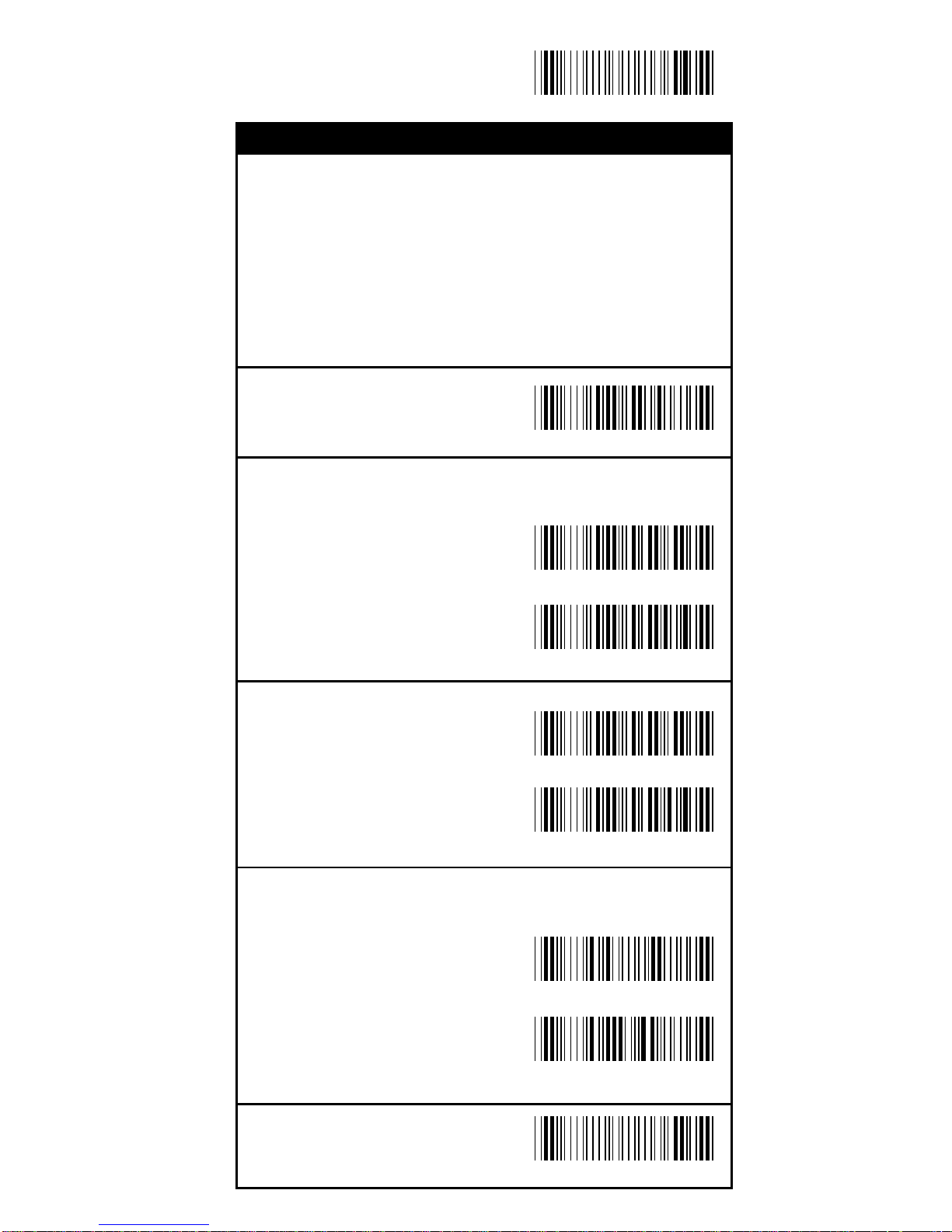
39
End Configuration
Save Configuration
Set Up Code Length
T o set the fixed length:
1. Sca n the "Begin" label of the de sired set.
2. Go to the Decimal Value Tabl es in Appendix A, scan
label(s) that represents the length to be read.
3. Sca n the "Complete" label of the desired set.
Repeat the steps 1 - 3 to set additional lengths.
<Variable>
Fix Length (2 Sets Availa ble)
1st Set Begin
(Then scan value in
Appendix A)
1st Set Complete
2nd Set Begin
(Then scan value in
Appendix A)
2nd Set Complete
Minimum Length
Begin(Then scan value
in Appendix A)
Complete
%4 K 1 +
%4 K 0 0
%4 K 0 0
%4 K 0 1
%4 K 0 2
%2 + - /
%2 C 6 +
Code 93
Symbology
Page 40
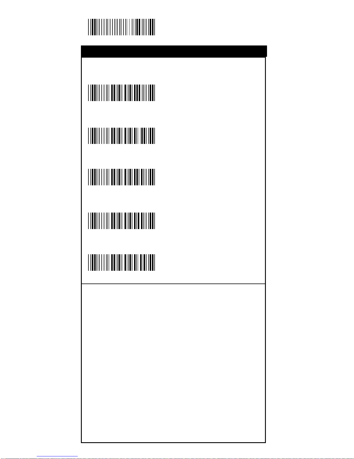
40
Start Configuration
Check Digit Transmission
<Do Not Calculate
Check Digit>
Calculate Check 1
Digit & Transmit
Calculate Check 1 Digit
& Not Tra nsmit
Calculate Check 2
Digits & Transmit
Calculate Check 2
Digits & Not T ransmit
%0 L N 3
%0 L N 7
%0 L N 5
%0 L N 6
%0 L N 4
Code 11
Symbology
Page 41
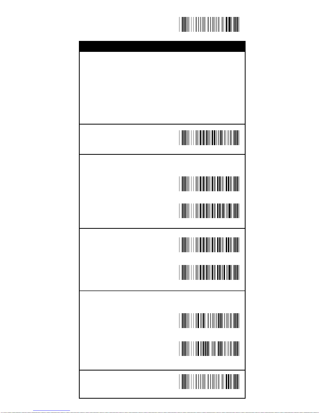
41
End Configuration
Save Configuration
Set Up Code Length
T o set the fixed length:
1. Sca n the "Begin" label of the de sired set.
2. Go to the Decimal Value Tabl es in Appendix A, scan
label(s) that represents the length to be read.
3. Sca n the "Complete" label of the desired set.
Repeat the steps 1 - 3 to set additional lengths.
<Variable>
Fix Length (2 Sets Availa ble)
1st Set Begin
(Then scan value in
Appendix A)
1st Set Complete
2nd Set Begin
(Then scan value in
Appendix A)
2nd Set Complete
Minimum Length
Begin(Then scan value
in Appendix A)
Complete
%4L1+
%4L00
%4L00
%4L01
%4L02
%2 + - /
%2 C 7 +
Code 11
Symbology
Page 42
42
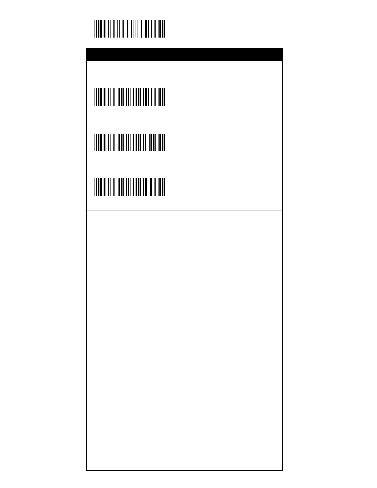
Start Configuration
Check Digit Transmission
<Do Not Calculate
Check Digit>
Calculate Check
Digit & Transmit
Calculate Check
Digit & Not T ransmit
%0 NN3
%0 NN7
%0 NN5
MSI/PLESSEY
Symbology
Page 43
43
End Configuration
Save Configuration
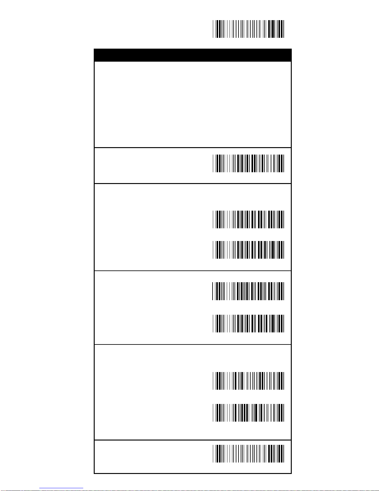
Set Up Code Length
T o set the fixed length:
1. Sca n the "Begin" label of the de sired set.
2. Go to the Decimal Value Tabl es in Appendix A, scan
label(s) that represents the length to be read.
3. Sca n the "Complete" label of the desired set.
Repeat the steps 1 - 3 to set additional lengths.
<Variable>
Fix Length (2 Sets Availa ble)
1st Set Begin
(Then scan value in
Appendix A)
1st Set Complete
2nd Set Begin
(Then scan value in
Appendix A)
2nd Set Complete
Minimum Length
Begin(Then scan value
in Appendix A)
Complete
%4 N 1 +
%4 N 0 0
%4 N 0 0
%4 N 0 1
%4 N 0 2
%2 + - /
%2 C 9 +
MSI/PLESSEY
Symbology
Page 44
44
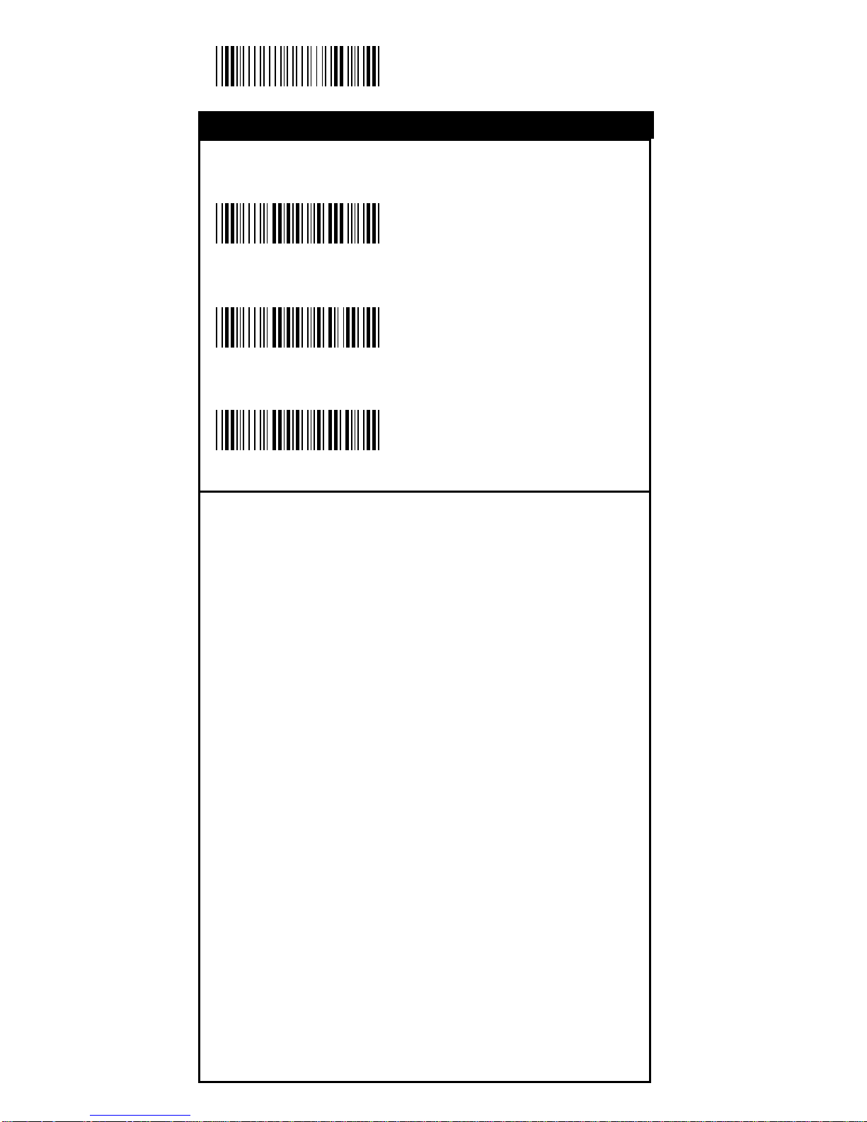
Start Configuration
Check Digit Transmission
Do Not Calculate
Check Digit
<Calculate Check
Digit & Transmit>
Calculate Check
Digit & Not T ransmit
%0 O N 3
%0 O N 7
%0 O N 5
BC 412
Symbology
Page 45
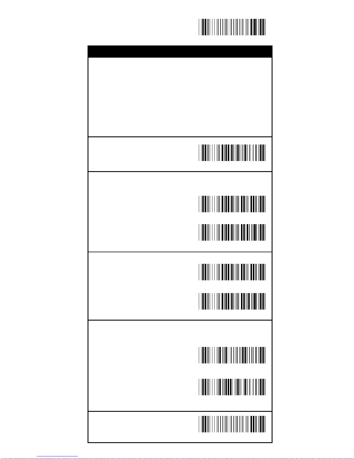
45
End Configuration
Save Configuration
Set Up Code Length
T o set the fixed length:
1. Sca n the "Begin" label of the de sired set.
2. Go to the Decimal Value Tabl es in Appendix A, scan
label(s) that represents the length to be read.
3. Sca n the "Complete" label of the desired set.
Repeat the steps 1 - 3 to set additional lengths.
<Variable>
Fix Length (2 Sets Availa ble)
1st Set Begin
(Then scan value in
Appendix A)
1st Set Complete
2nd Set Begin
(Then scan value in
Appendix A)
2nd Set Complete
Minimum Length
Begin(Then scan value
in Appendix A)
Complete
%4 O 1 +
%4 O 0 0
%4 O 0 0
%4 O 0 1
%4 O 0 2
%2 + - /
%2 C A +
BC 412
Symbology
Page 46
46
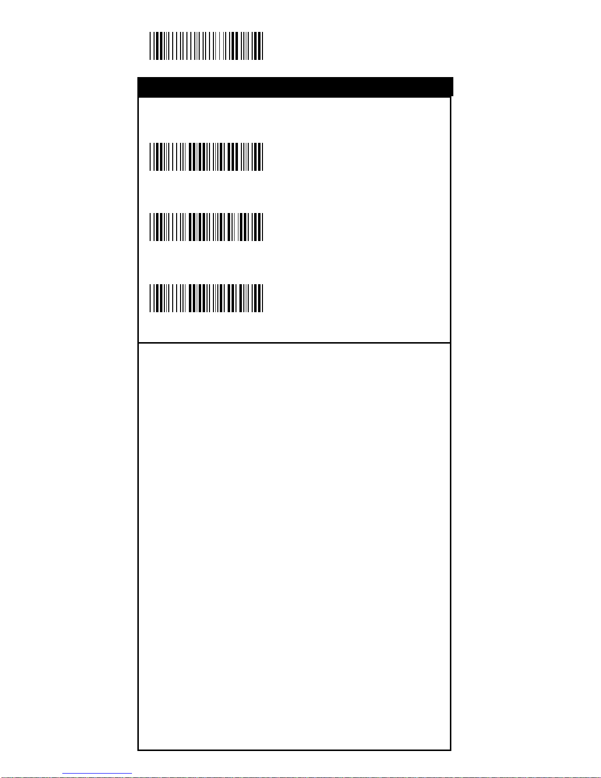
Start Configuration
Check Digit Transmission
<Do Not Calculate
Check Digit>
Calculate Check
Digit & Transmit
Calculate Check
Digit & Not T ransmit
%0 M N 3
%0 M N 7
%0 M N 5
China Postage
Symbology
Page 47
47
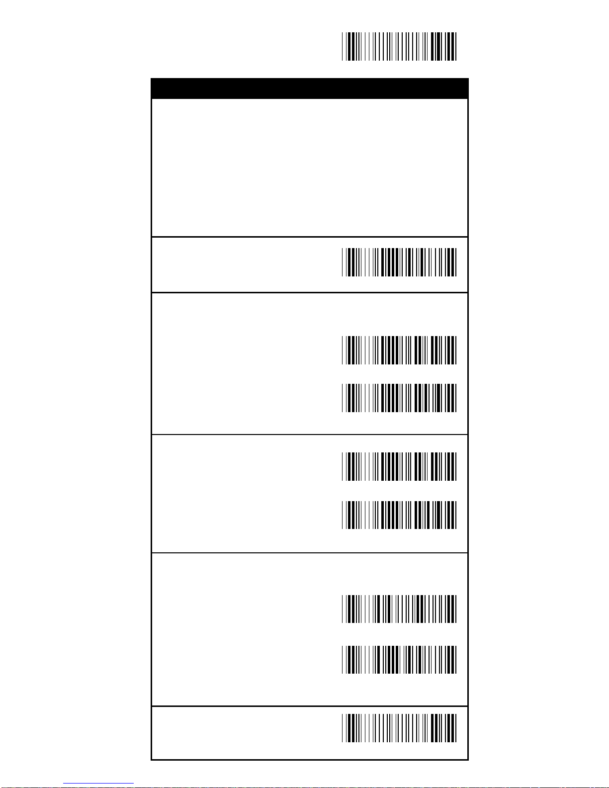
End Configuration
Save Configuration
Set Up Code Length
T o set the fixed length:
1. Sca n the "Begin" label of the de sired set.
2. Go to the Decimal Value Tabl es in Appendix A, scan
label(s) that represents the length to be read.
3. Sca n the "Complete" label of the desired set.
Repeat the steps 1 - 3 to set additional lengths.
<Variable>
Fix Length (2 Sets Availa ble)
1st Set Begin
(Then scan value in
Appendix A)
1st Set Complete
2nd Set Begin
(Then scan value in
Appendix A)
2nd Set Complete
Minimum Length
Begin(Then scan value
in Appendix A)
Complete
%4 M 1 +
%4 M 0 0
%4 M 0 0
%4 M 0 1
%4 M 0 2
%2 + - /
%2 C 8 +
China Postage
Symbology
Page 48
48
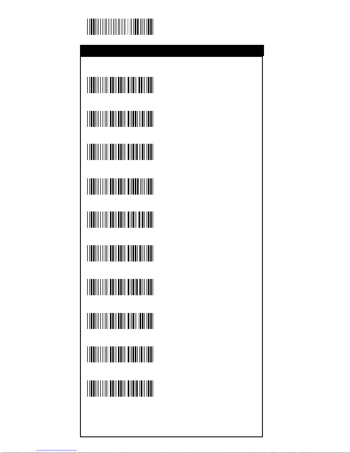
Start Configuration
<US English>
UK English
Italian
Spa nish
French
Germany
Swedish
Swiss
Hungaria n
Japanese
%0 Z V 0
%0 Z V 1
%0 Z V 2
%0 Z V 3
%0 Z V 4
%0 Z V 5
%0 Z V 6
%0 Z V 7
%0 Z V 8
%0 Z V 9
La nguage Selection
Operation
Page 49
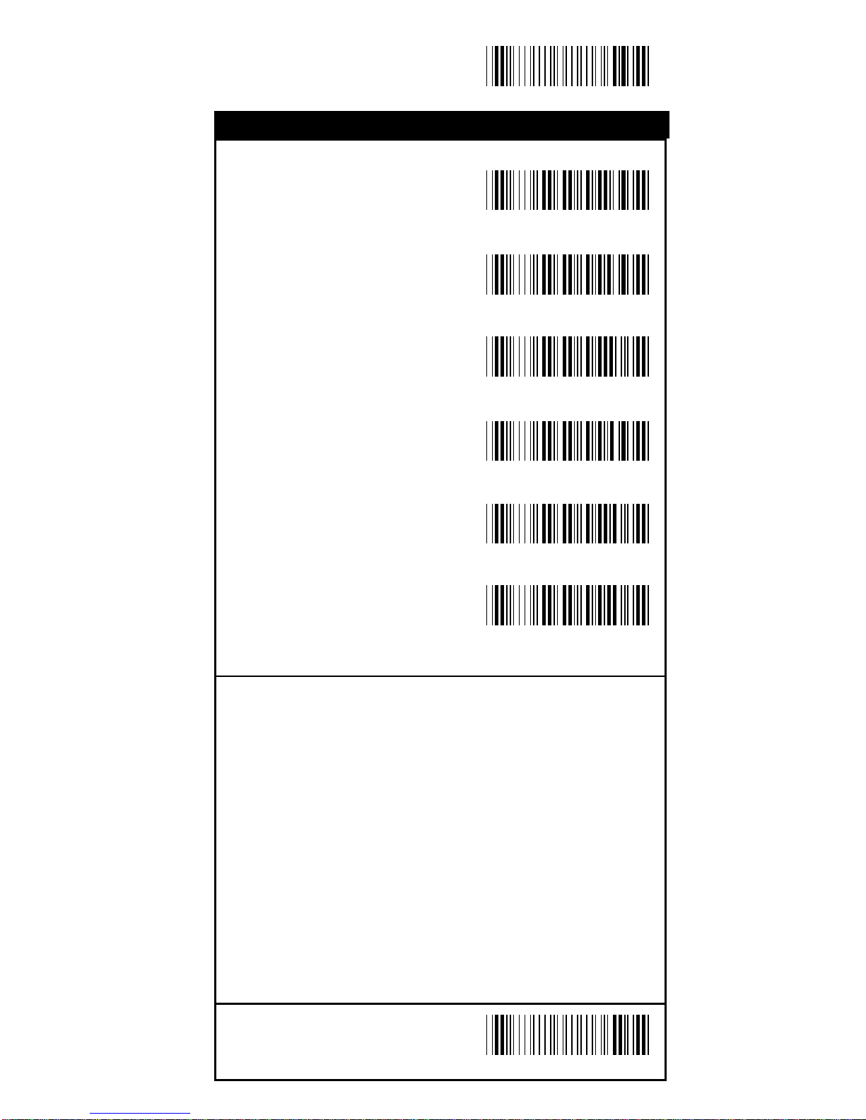
49
End Configuration
Save Configuration
Belgium
Portugal
Demark
Holland
Reserved1
Reserved2
%0 Z V A
%0 Z V B
%0 Z V C
%0 Z V D
%0 Z V E
%0 Z V F
La nguage Selection
Operation
Page 50
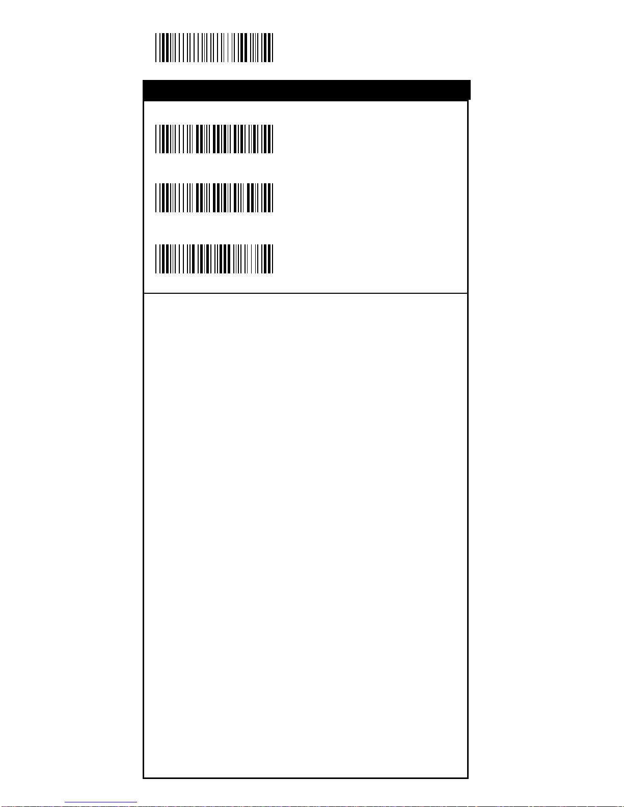
50
Start Configuration
ON
<OFF>
Default
With this function ON, a leading character will be a dded to
the output string while scanning code, user may refer to the
following table to know what kind of bar code is being
scanned.
Plea se refer to the table below f or matching code ID of codes
read in.
Code Type ID Code Type ID
UPC-A A UPC-E B
EAN-8 C EAN-13 D
CODE 39 E CODE 128 F
Interleave 25 G Industrial 25 H
Matrix 25 I Codabar/NW7 J
CODE 93 K CODE 11 L
China Postage M MSI/PLESSEY N
BC412 O
1st Track X 2nd Track Y
3rd T ra ck Z
User Define Code ID
To set the code ID:
1. Sca n the symboligie s la bel.
2. Go to the ASCII Tables in Appendix B, scan label that
represents the desired code ID.
Note:Note:
Note:Note:
Note:
User define code ID will override default value.User define code ID will override default value.
User define code ID will override default value.User define code ID will override default value.
User define code ID will override default value.
Program will not check the conflict. It is possible to haveProgram will not check the conflict. It is possible to have
Program will not check the conflict. It is possible to haveProgram will not check the conflict. It is possible to have
Program will not check the conflict. It is possible to have
more than two symboligies which have same code ID.more than two symboligies which have same code ID.
more than two symboligies which have same code ID.more than two symboligies which have same code ID.
more than two symboligies which have same code ID.
%0 0 H 1
%0 0 H 0
%913+
Bar Code ID
Operation
Page 51
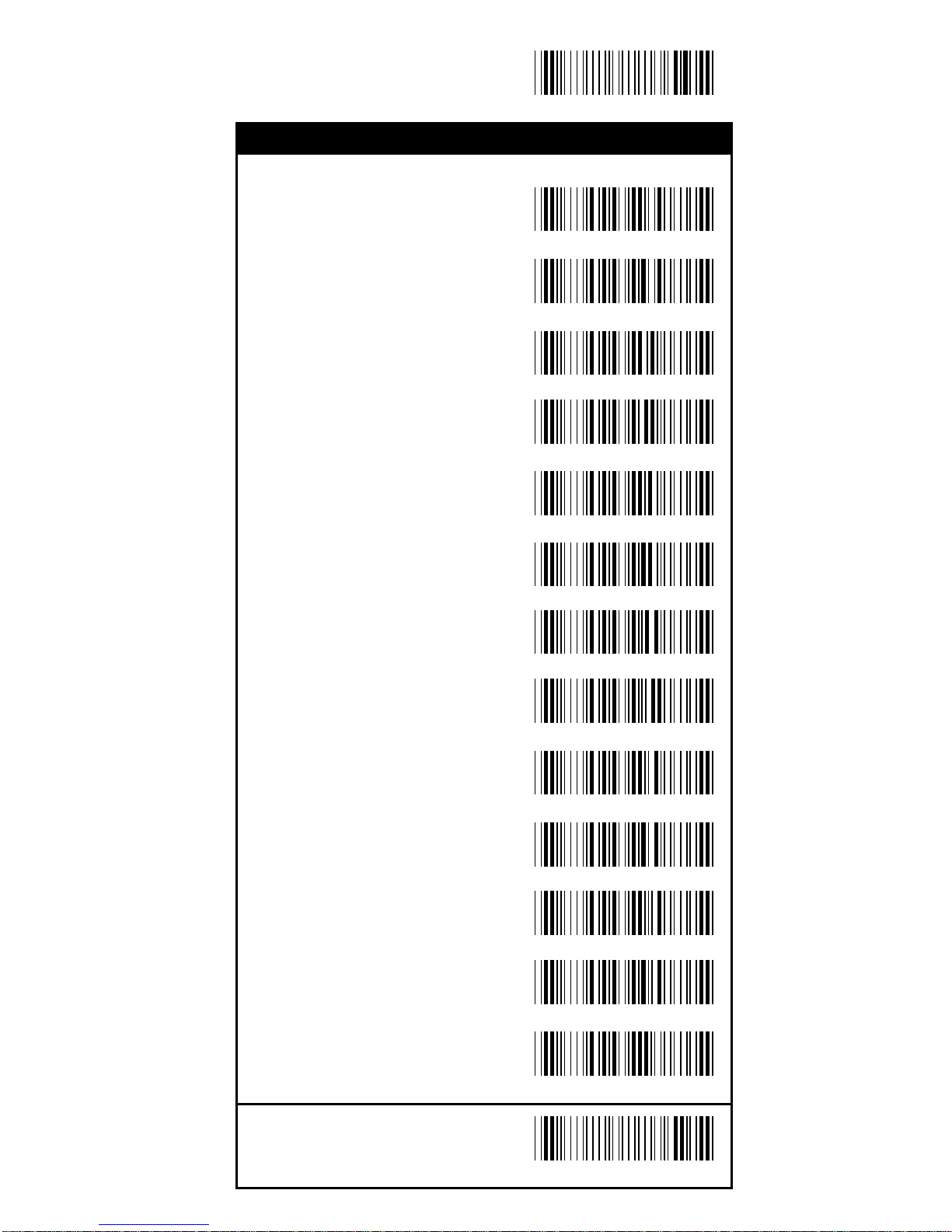
51
End Configuration
Save Configuration
UPC-A
UPC-E
EAN-13/JAN-13
EAN-8/JAN-8
CODE 39
CODE 128
CODABAR/NW7
Interleave 25
Industrial 25
Matrix 25
CODE 93
CODE 11
China Postage
%9 1 A +
%9 1 B +
%9 1 Y +
%9 1 Z +
%9 1 E +
%9 1 F +
%9 1 G +
%9 1 H +
%9 1 I +
%9 1 J +
%9 1 K +
%91L+
%9 1 M +
Bar Code ID
Operation
Page 52
52
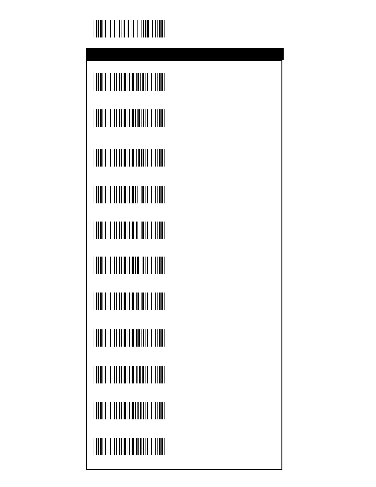
Start Configuration
MSI/PLESSEY
BC412
Mag. Track1
Mag. Track2
Mag. Track3
Reserved1
Reserved2
Reserved3
Reserved4
Reserved5
Reserved6
%910+
%911+
%912+
%9 1 C +
%9 1 D +
%9 1 P +
%9 1 Q +
%9 1 R +
%9 1 S +
Bar Code ID
%9 1 O +
%9 1 N +
Operation
Page 53
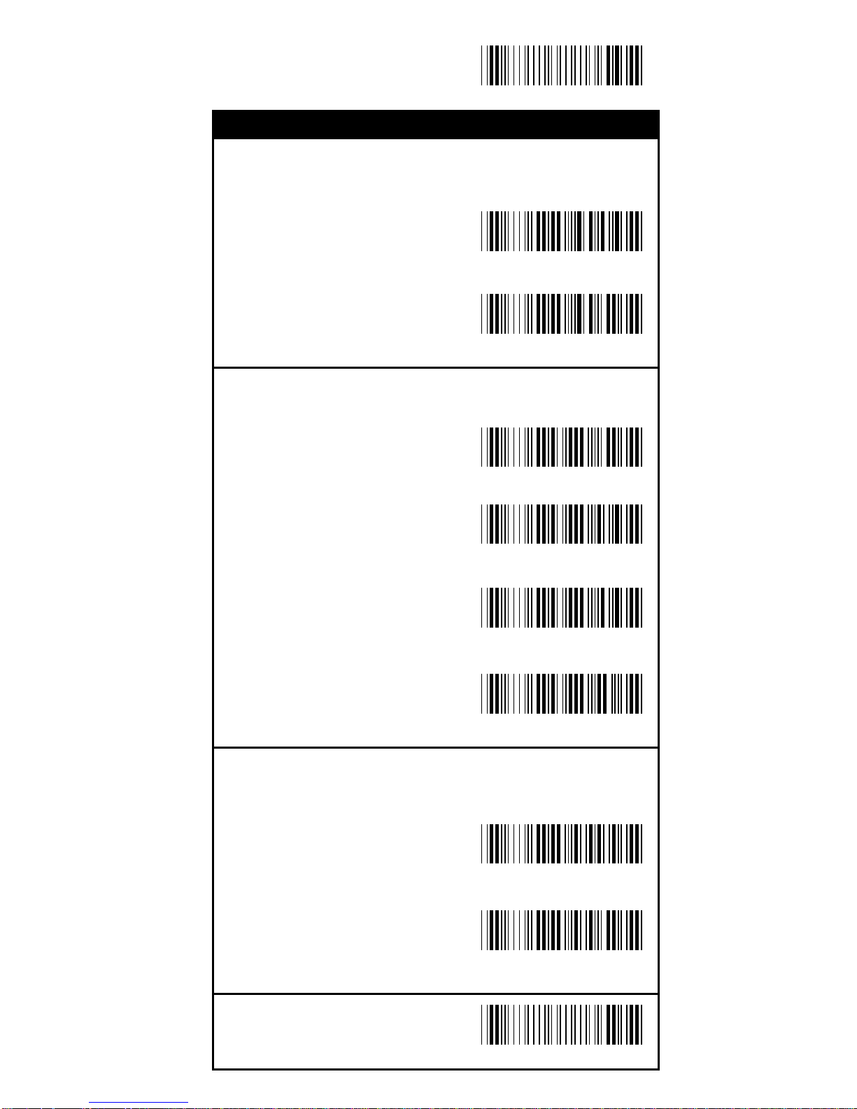
53
End Configuration
Save Configuration
Re ading Level
Bar Equals High
<Bar Equals Low>
Accura cy
<1 Time>
2 Ti mes
3 Ti mes
4 Ti mes
Sensitivity of Continuous Re a ding Mode
<Fast>
Slow
%0130
%0131
%0132
%0133
%0 3 I 0
%0 3 I 2
Misc. Para meters
Operation
%0388
%0380
Page 54
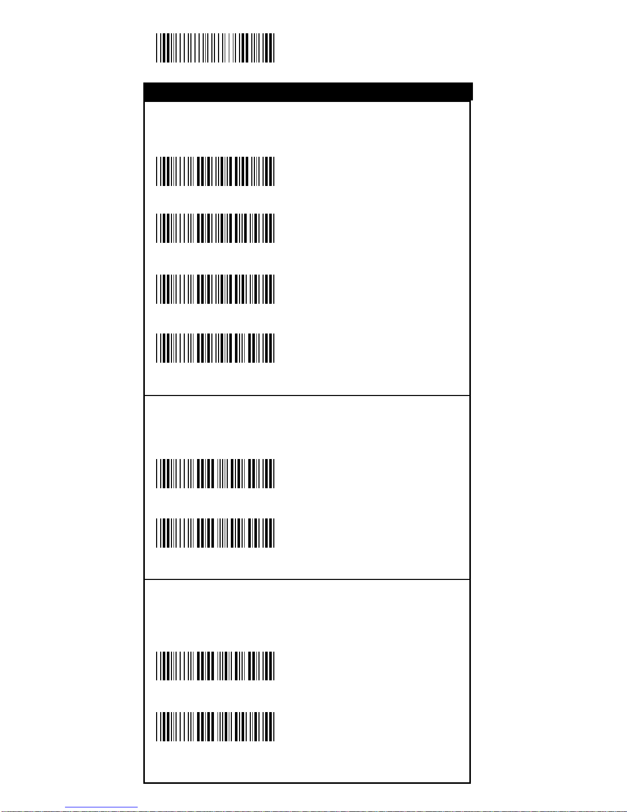
54
Start Configuration
Buzzer Beep Tone
<High>
Medium
Low
Off
PnP/Notebooks
<Disable>
Enable
Reverse Output Chara cters
<Disable>
Enable
%0 1 J 3
%0 1 J 2
%0 1 J 1
%0 1 J 0
%0 3 H 0
%0 3 H 1
Misc. Para meters
Operation
%0340
%0344
Page 55
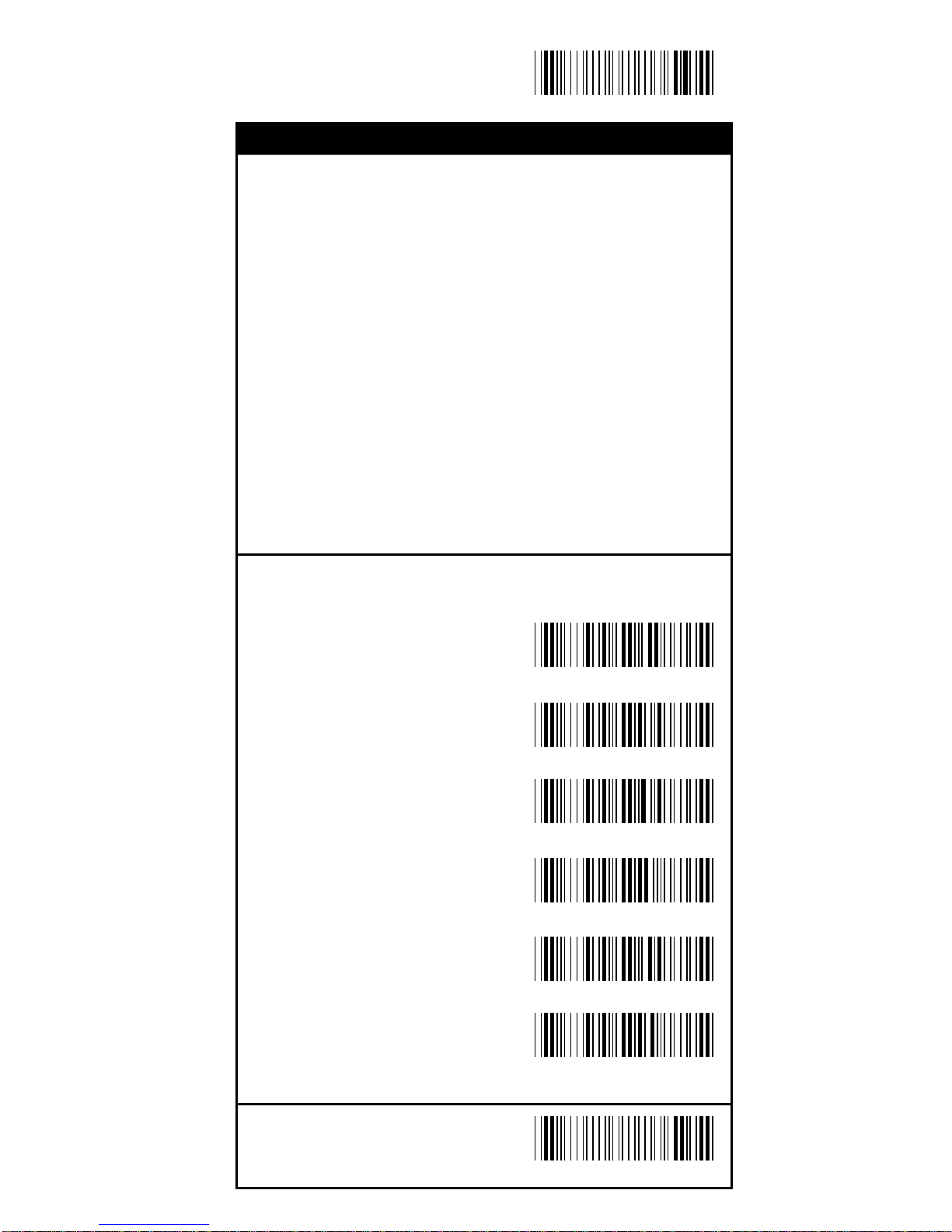
55
End Configuration
Save Configuration
Setup Deletion
To setup the deletion of output characters:
1. Sca n the label of the desired set below.
2. Sca n the label of the de sired symboligy.
3. Go to the Decimal Value Tabl es in Appendix A, scan
label(s) that represents the desired position to be deleted.
4. Sca n the "Complete" label of "Chara cter Position to be
Deleted".
5. Go to the Decimal Value Tabl es in Appendix A, scan
label(s) that represents the number of characters to be
deleted.
6. Scan the "Complete" la bel of "Number of Characters to
be Deleted".
Repeat the steps 1 - 6 to set additional deletion.
Select Deletion Set Number
1. 1st Set
2. 2nd Set
3. 3rd Set
4. 4th Set
5. 5th Set
6. 6th Set
%800+
%801+
%802+
%803+
%804+
%805+
Setup Deletion
Operation
Page 56
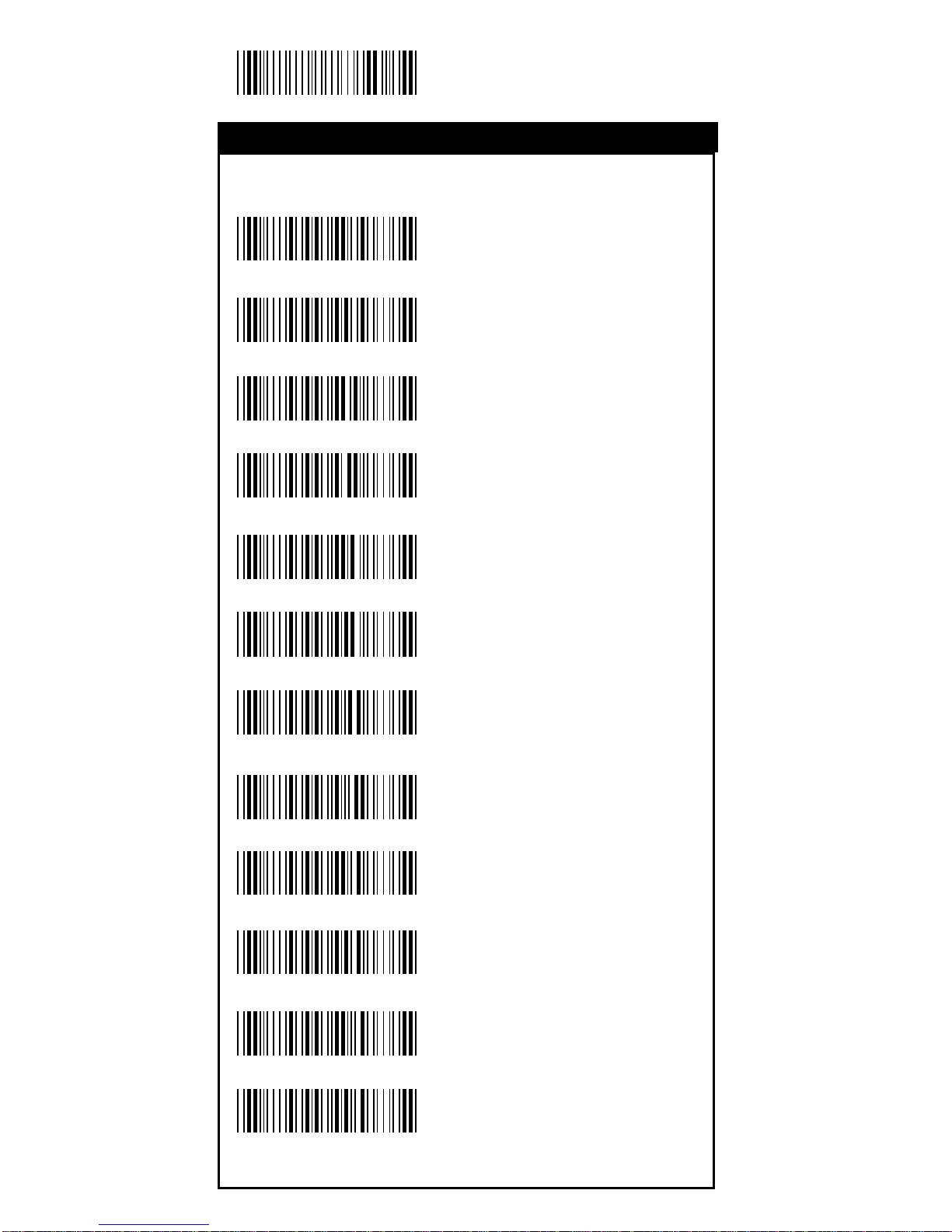
56
Start Configuration
Symboligies Sele ction
UPC-A
UPC-E
EAN-13/JAN-13
EAN-8/JAN-8
CODE 39
CODE 128
CODABAR/NW7
Interleave 25
Industrial 25
Matrix 25
CODE 93
CODE 1 1
%8 1 A +
%8 1 B +
%8 1 Y +
%8 1 Z +
%8 1 E +
%8 1 F +
%8 1 J +
%8 1 G +
%8 1 H +
%8 1 I +
%8 1 K +
%81L+
Setup Deletion
Operation
Page 57
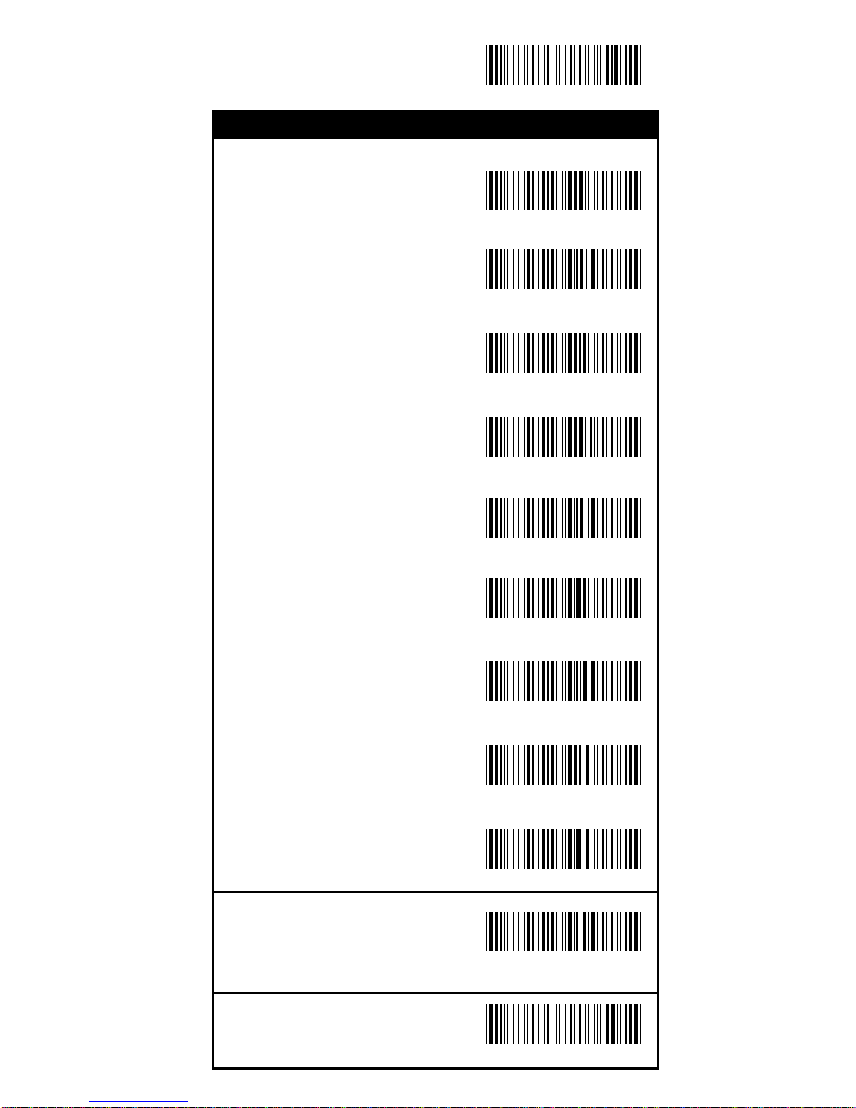
57
End Configuration
Save Configuration
China Postage
MSI/PLESSEY
BC412
Resvered1
Resvered2
Resvered3
Resvered4
Resvered5
Resvered6
None
%8 1 O +
%8 1 C +
%8 1 D +
%8 1 P +
%8 1 Q +
%8 1 R +
%8 1 S +
%814+
%8 1 M +
%8 1 N +
Setup Deletion
Operation
Page 58
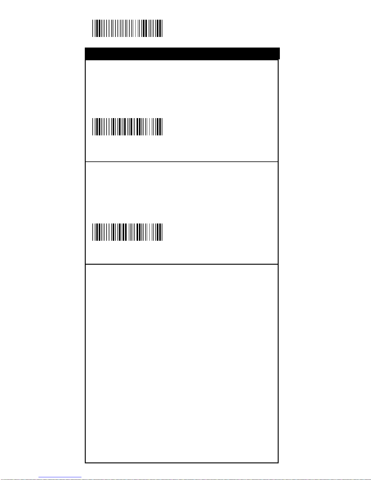
58
Start Configuration
Character Position to be Deleted
1. Scan De ci mal Value
in Appendix A first.
2. Complete
Number of Characters to be Deleted
1. Scan De ci mal Value
in Appendix A first.
2. Complete
Setup Deletion
%820+
%830+
Operation
Page 59
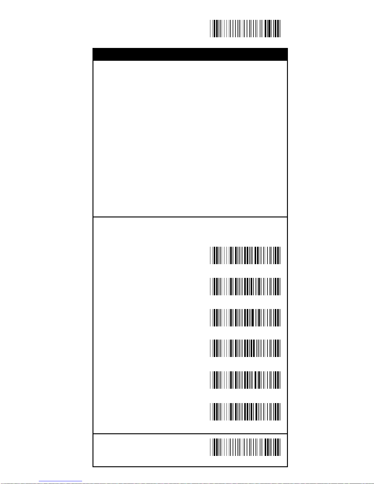
59
End Configuration
Save Configuration
Setup Insertion
To setup the insertion of output characters:
1. Scan the la bel of the desired set.
2. Sca n the label of the de sired symboligy.
3. Go to the Decimal Value Tabl es in Appendix A, scan
label(s) that represents the desired position to be inserted.
4. Sca n the "Complete" label of "Chara cter Position to be
Inserted".
5. Go to the ASCII Tables in Appendix B or Function Key
Tables in Apendix C, scan label(s) that represents the
desired characters to be inserted.
6. Scan the "Complete" la bel of "Characters to be In serted".
Repeat the steps 1 - 6 to set additional insertion.
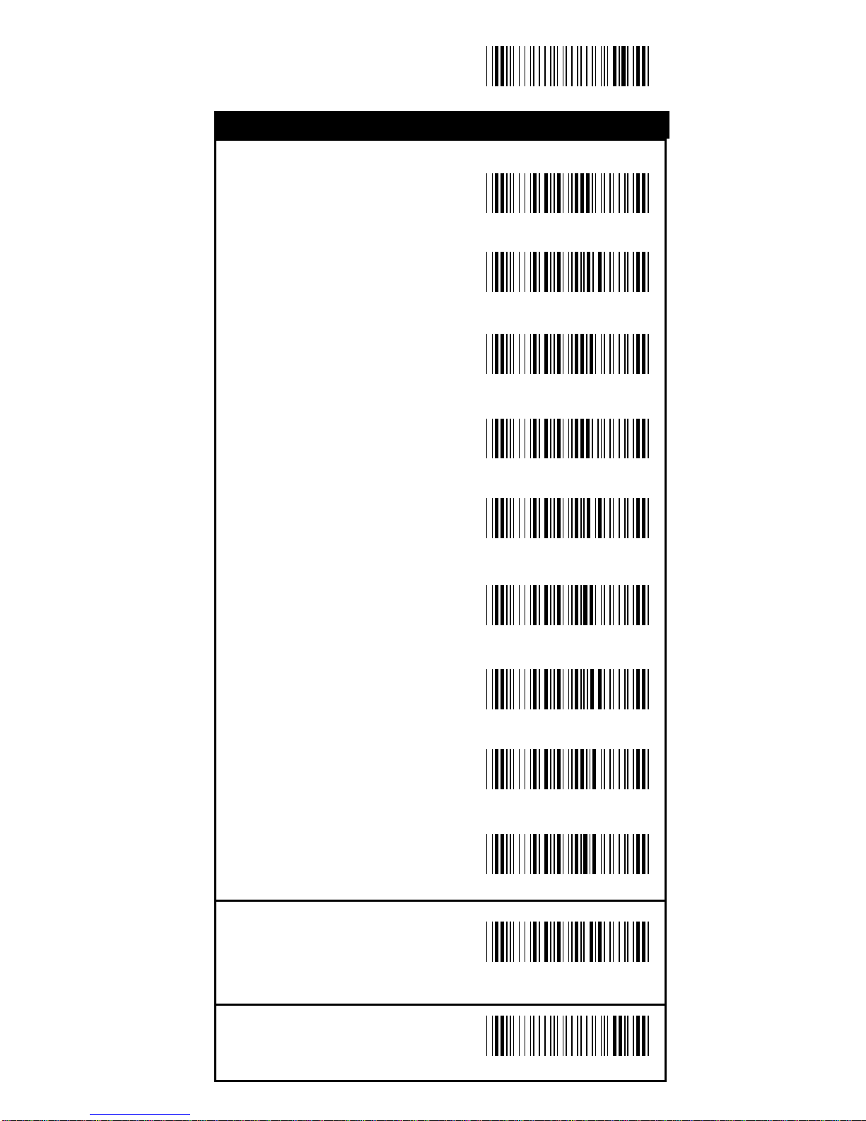
Select Insertion Set Number
1st Set
2nd Set
3rd Set
4th Set
5th Set
6th Set
%500+
%502+
%503+
%504+
%505+
%501+
Setup Insertion
Operation
Page 60
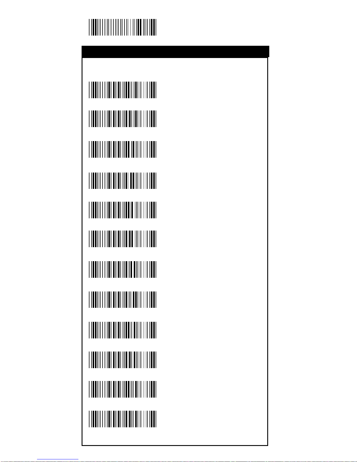
60
Start Configuration
Symboligies Sele ction
UPC-A
UPC-E
EAN-13/JAN-13
EAN-8/JAN-8
CODE 39
CODE 128
CODABAR/NW7
Interleave 25
Industrial 25
Matrix 25
CODE 93
CODE 1 1
Setup Insertion
%5 1 A +
%5 1 B +
%5 1 Y +
%5 1 Z +
%5 1 E +
%5 1 F +
%5 1 G +
%5 1 J +
%5 1 H +
%5 1 I +
%5 1 K +
%51L+
Operation
Page 61
61
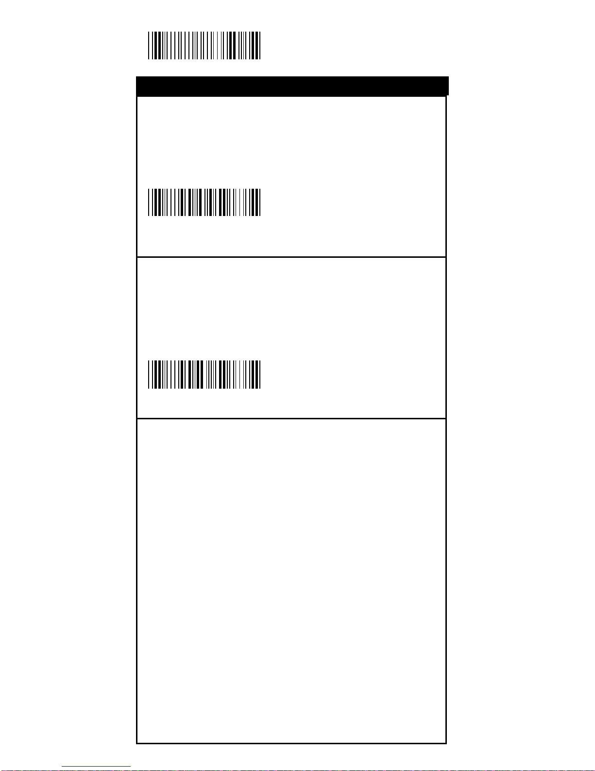
End Configuration
Save Configuration
China Postage
MSI/PLESSEY
BC412
Resvered1
Resvered2
Resvered3
Resvered4
Resvered5
Resvered6
None
%5 1 C +
%5 1 Q +
Setup Insertion
%514+
%5 1 O +
%5 1 D +
%5 1 P +
%5 1 S +
%5 1 R +
%5 1 M +
%5 1 N +
Operation
Page 62
62
Start Configuration
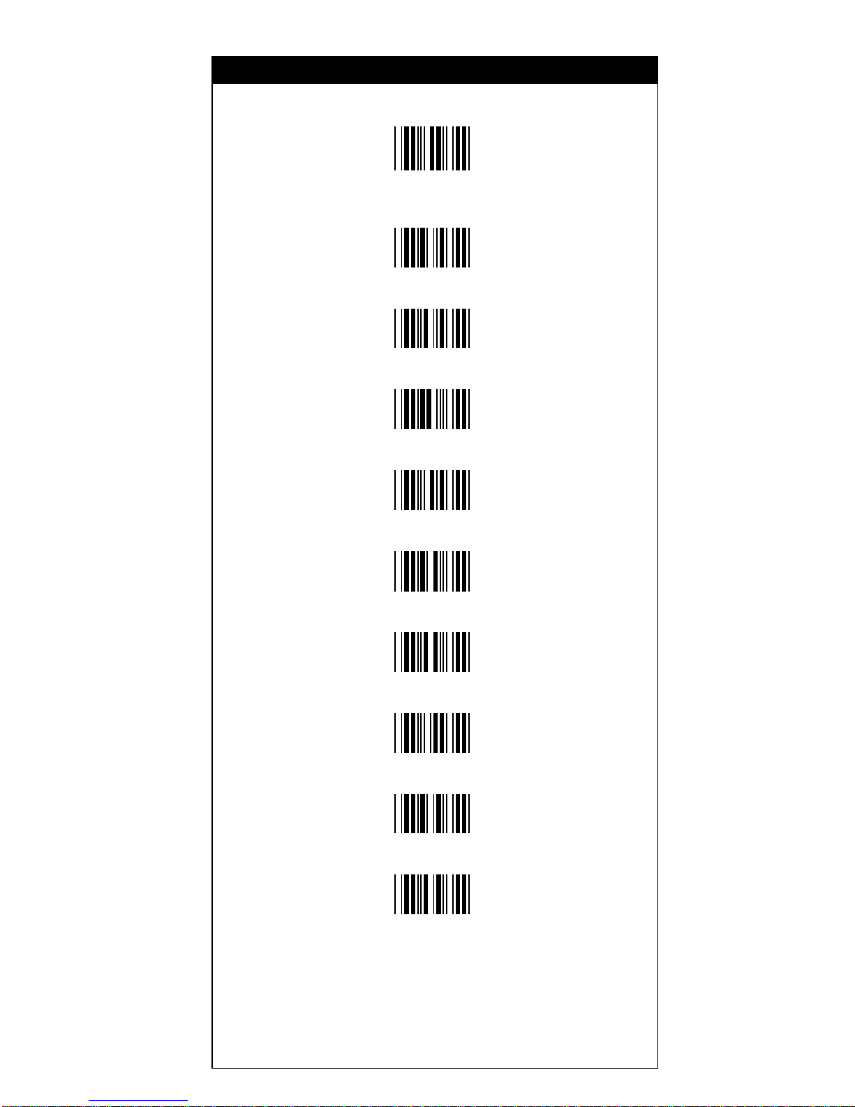
Chara cter Position to be Inserted
1. Scan De ci mal Value
in Appendix A first.
2. Complete
Characters to be Inserted
1. Scan ASCII Table
in Appendix B f irst.
2. Complete
Setup Insertion
%520+
%530+
Operation
Page 63
63
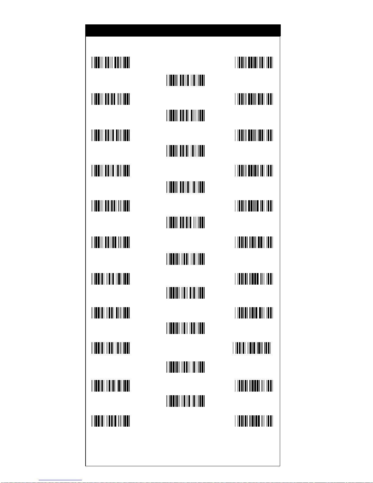
8
0
1
2
3
4
5
6
7
9
Decimal Value
Appendix A
Page 64
64
NULL SOH
STX
ETX EOT
ENQ
ACK BEL
BS
HT LF
VT
FF CR
SO
SI DLE
DC1
DC2 DC3
DC4
NAK SYN
ETB
CAN E M
SUB
ESC FS
GS
RS US
03
00
02
01
04
05
06 07
08
09 0A
0B
0C 0D
0E
0F 10
11
12 13
14
15 16
17
18 19
1A
1B 1C
1D
1E 1F
ASCll Ta bles
Appendix B
Page 65
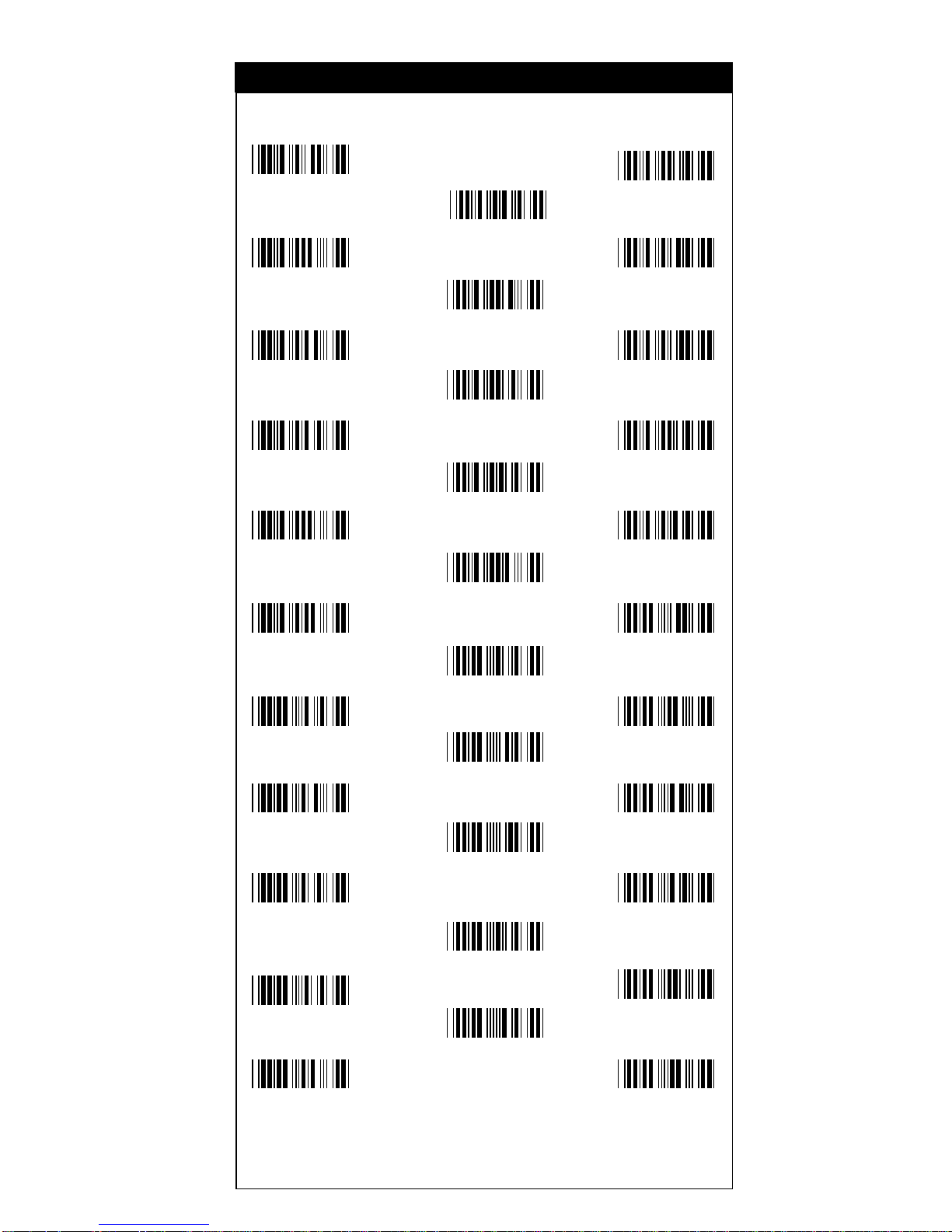
65
SPACE !
"
#$
%
&'
(
)*
+
,-
.
/0
1
23
4
56
7
89
:
;<
=
>?
20
21
22
23 24
25
26 27
28
29 2A
2B
2C 2D
2E
2F 30
31
32 33
34
35 36
37
38 39
3A
3B
3C
3D
3E 3F
ASCll Ta bles
Appendix B
Page 66
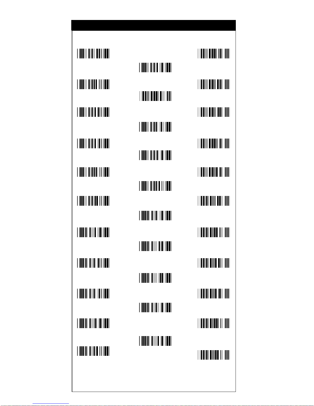
66
@A
B
CD
E
FG
H
IJ
K
LM
N
OP
Q
RS
T
UV
W
XY
Z
[\
]
^_
40 41
42
43 44
45
46 47
48
49 4A
4B
4C
4E
4D
4F 50
51
52 53
54
55 56
57
58 59
5A
5B 5C
5D
5E
5F
ASCll Ta bles
Appendix B
Page 67
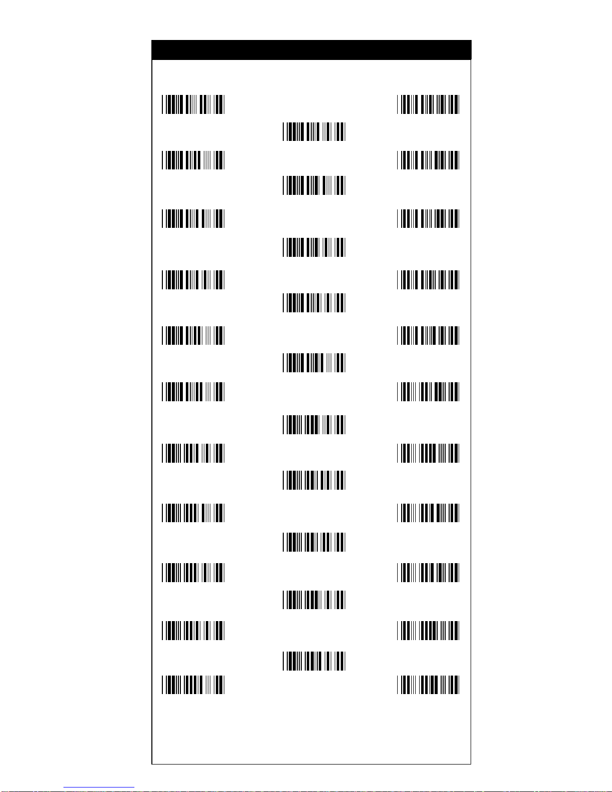
67
`a
b
cd
e
fg
h
ij
k
lm
n
op
q
rs
t
uv
w
xy
z
{|
}
~ DEL
60 61
62
63 64
65
66 67
68
69 6A
6B
6C 6D
6E
6F 70
71
72 73
74
75 76
77
78 79
7A
7B 7C
7D
7E 7F
ASCll Ta bles
Appendix B
Page 68
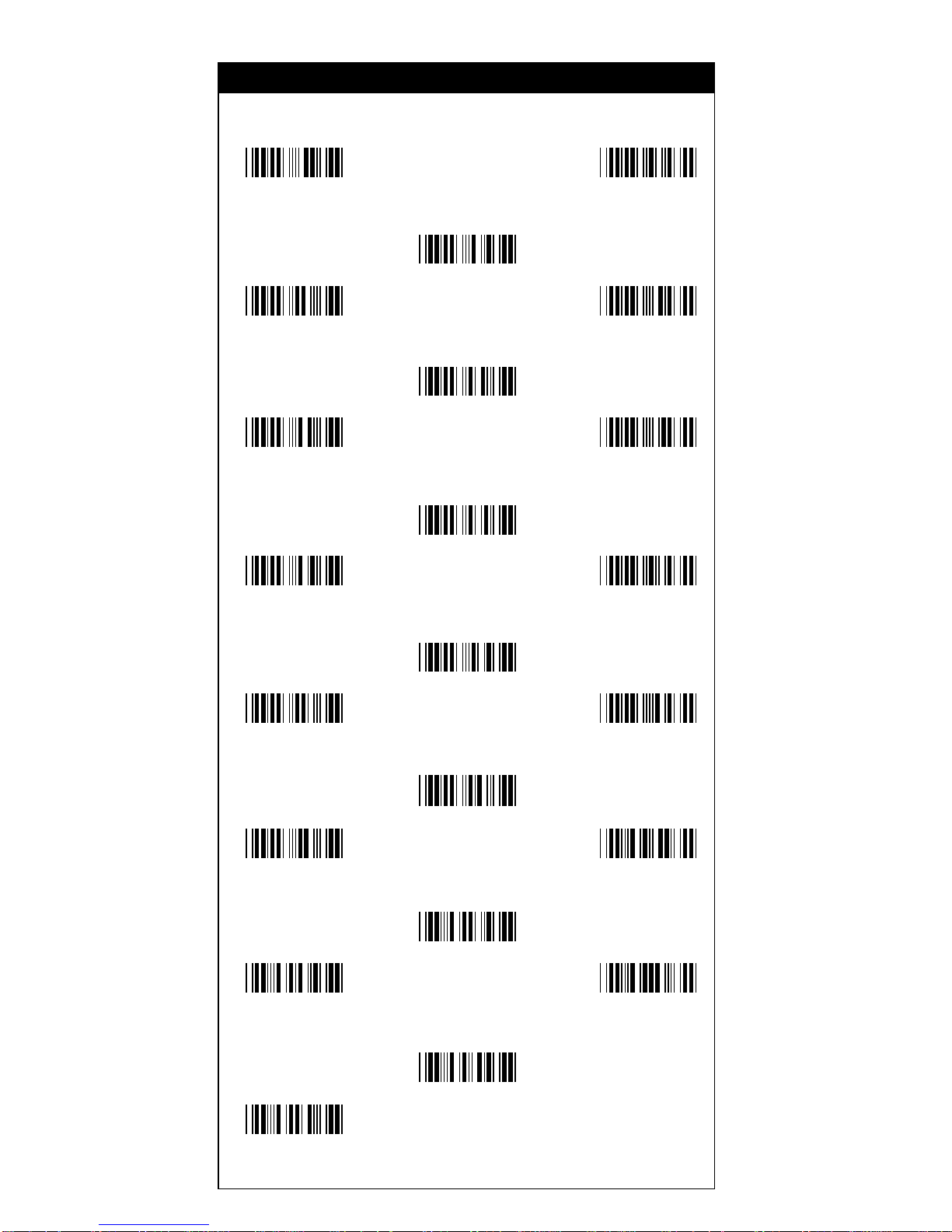
68
F1 F2
F3
F4 F5
F6
F7 F8
F9
F10 F11
F12
Insert Delete
Home
Page Up Page Down
End
Left Right
Up
Down
C1C0
C2
C3 C4
C5
C6 C7
C8
C9 CA
CB
CC CD
CE
CF D0
D1
D2 D3
D4
D5
Function Key Tabl es
Appendix C
 Loading...