

Page 1
®
T
h
ki
a
norTh
p
a
w
T
R
In
r
e
C
opyright 2
0
e informati
o
nd with rega
d fitness fo
r
consequen
t
is docume
n
rt of this do
c
r
itten conse
n
ADEMAR
K
tel®, Pentiu
m
gistered tra
d
11 April All
n contained
rd to this m
a
a particular
ial damage
s
t contains p
r
ument may
t of the ma
n
® and MM
X
emarks of
M
Rights Rese
in this docu
m
terial, inclu
d
purpose. W
in connecti
o
oprietary in
f
be photoco
p
ufacturer.
are regist
e
icrosoft Co
r
rved Versio
n
ent is subj
e
ing, but not
l
e shall not b
n with the f
u
ormation th
a
ied, reprod
u
red tradem
a
poration.
1.0
ct to chang
e
limited to, th
e liable for
e
rnishing, p
e
t is protect
e
ced or tran
s
rks of Intel
®
without no
t
e implied w
a
rrors contai
n
rformance,
o
d by copy ri
g
lated to an
o
Corporatio
n
ice. We ma
k
rranties of
m
ed herein o
r
r use of thi
s
ht. All right
s
ther langua
g
. Microsoft
®
e no warran
erchantabil
i
for inciden
t
material.
are reserv
e
e without th
and Wind
o
ty of any
ty
al
d. No
e prior
ws® are
Page 2

1
Main Board
CPU
PP7000D-15 Intel® Atom™ processor D525 (1M Cache, 1.80 GHz)
PP6000D-12 Intel® Atom™ processor D525 (1M Cache, 1.80 GHz)
Chipset Intel® NM10 Express Chipset
System Memory Socket-type RAM device, 204PIN SO-DIMM DDR3 RAM, up to 4GB
Graphic Memory Shared system memory up to 256MB
LCD Panel
PP7000D-15
Panel Size 15”
Maximum Resolution 1024 x 768
Brightness 250 cd/m1
Contrast Ratio 600 : 1
Response Time 8 ms
View Angles (H/V) 160 / 160
Touch Panel Five Wires Resistive
PP6000D-12
Panel Size 12.1”
Maximum Resolution 1024 x 768
Brightness 195 cd/m1
Contrast Ratio 400 : 1
Response Time 16 ms
View Angles (H/V) 90 / 65
Touch Panel Five Wires Resistive
Storage
HDD 2.5” SATA interface
Compact Flush Type Ⅰ&Ⅱ
Expansion
Mini-PCIE Socket One
Power
Power Adaptor Input AC 100-240V 2.5A 50/60Hz, Output DC 12V 6.66A
1
Page 3

2
I / O
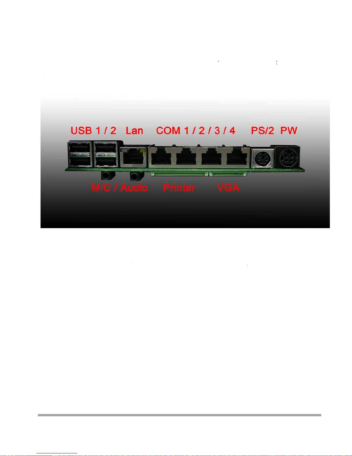
USB Six
Serial Four COM ports with RJ-45 Connector
Pin 9 with 5V / 12V power selectable
Parallel One LPT with adaptor cable
LAN One
2nd VGA Output One with optional adaptor cable
PS/2 One
Audio One Earphone & One Microphone
Control/Indicator
Power Button One
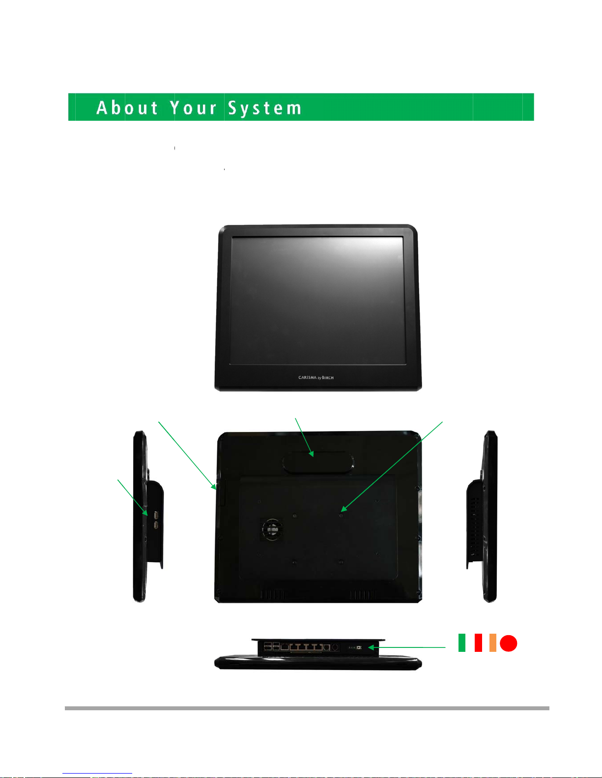
LED Indicators Power (Green), HDD (Red), LAN(Orange)
Optional Peripherals
Magnetic Card Reader ISO Track 1/2/3, USB interface
VFD customer display 20 x 2 characters, RS-232 interface
Dimensions
PP-7000D-15 358(W) X 300(L) X 52(H) mm
PP-6000D-12 294(W) X 235(L) X 45(H) mm
Environment
Operating Temperature 0°C ~ 40°C ( 32°F ~ 104°F )
Storage Temperature - 20°C ~ 60°C ( - 4°F ~ 140°F )
Operating Humidity 10% - 80% RH non condensing
Storage Humidity 10% - 80% RH non condensing
Model Number
PPS000DX – SS Intel® Atom™ processor D525 (1M Cache, 1.80 GHz)
X : M --- Shinny Black housing
Q --- Dull Black housing
W – Shinny White housing
S000DX-SS: 7000DX-15 --- 15"TFT LCD
6000DX-12 --- 12"TFT LCD
Page 4
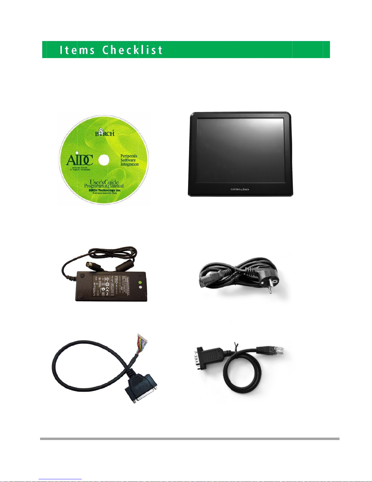
If
T
apr
any item
ke the syst
e
otect the sy
s
1
5. Pri
is missin
g
m unit out f
r
tem. The fo
. CD that in
c
driver and
. Power
A
nter Port co
n
, please
om the cart
o
llowing item
s
luding all
manual
daptor
version ca
b
ontact y
o
n. Remove
should be
f
le
ur sale
a
the unit by
c
ound in the
gent imm
arefully hol
d
carton:
2.
T
4. A
C
6. Tw
o
conv
e
ediately.
ing the foa
m
he System
Power Cor
d
RS-232 po
rsion cable
s
inserts an
d
rt
2
remove slo
w
3
ly to
Page 5

7. Sec
o
nd Display
c
able (Optional)
4
Page 6
P
s
tto
lease un
p
andby p
o
your sy
s
USBx2
M
lug the A
C
wer is al
w
tem whe
n
SR(Option
power
o
ays on a
f
you ope
al)
f the ada
p
ter the a
d
n any par
t
pter befo
r
apter is
p
of it.
VFD(Opti
o
e openin
g
lugged i
n
nal)
any par
t
. It may c
7
of the sy
ause per
m
3
5x75mm
V
Power
tem. Sin
c
anent d
a
ESA
PowerSW
LAN
HDD
5
e the
mage
Page 7
P
D
P
1
.
a
n
Th
e
lease not
i
B-9 conv
e
lease noti
c
25 type c
o
d a centr
o
conn
e
ce that al
rsion ca
b
e that the
nnectors.
nic conn
e
ctor pa
l Four C
O
les are p
r
Printer a
n
The pack
a
ctor. The
V
nel
M ports
u
ovided i
n
d VGA co
n
ge includ
e
GA, Aud
i
sing RJ-
4
the pac
k
nnectors i
n
s a Print
e
io adapter
5 connec
t
age.
the seco
r Port ad
a
is optiona
or and t
w
d level, u
pter cable
l accessor
y
o RJ-45
t
sing JST
P
to conne
c
y.
o
HD pitch
t to this c
o
6
nnector
Page 8
7
Important Notice
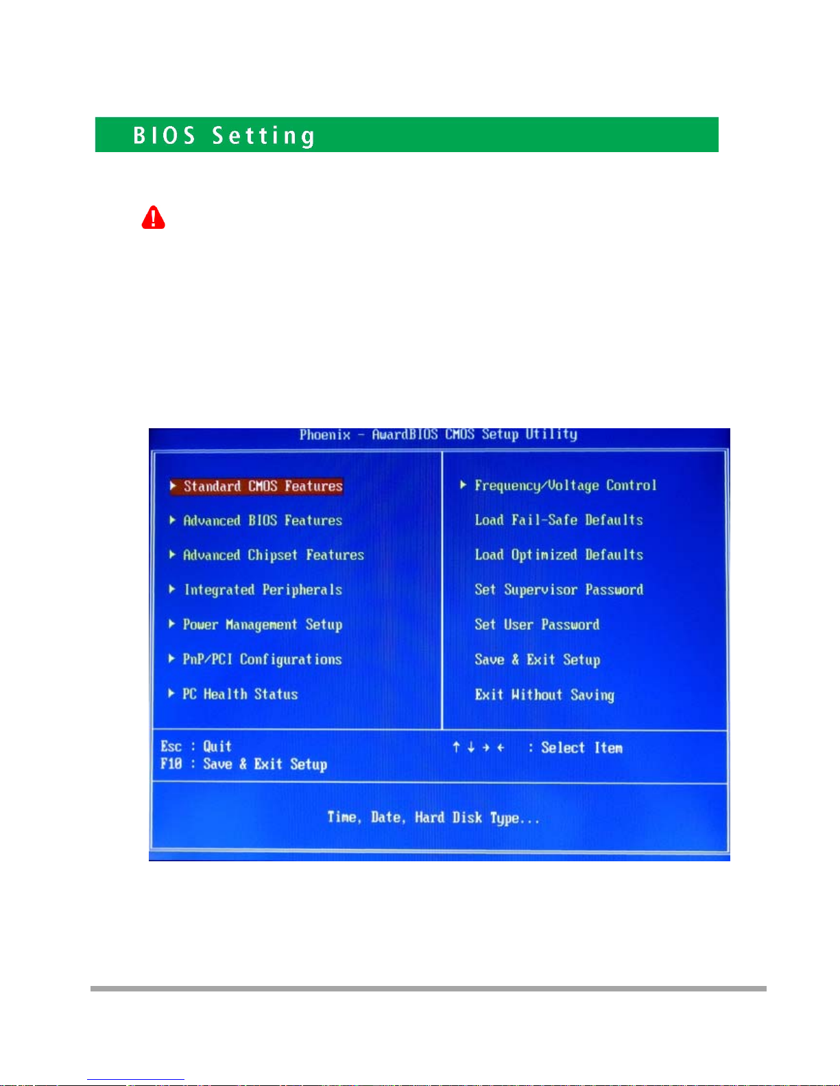
If you find the screen is completely dark when power on. Please Reset BIOS setting as
described in the former chapter. After clean CMOS operation, press <DEL> key many times
after power on beep sound to enter BIOS setup mode then press <F10> and <Enter>. It will set
BIOS to default value. Or connect a monitor to the second VGA port and enter BIOS setup
mode then Load Optimized Defaults and Save &Exit Setup.
Standard CMOS Features
Use this menu for basic system configuration.
4
Page 9

8
Advanced BIOS Features
Use this menu to set the Advanced Features available on the system.
Advanced Chipset Features
Use this menu to change the values in the chipset registers and optimize the system’s performance.
Integrated Peripherals
Use this menu to specify your settings for integrated peripherals.
Power Management setup
Use this menu to specify your settings for power management.
PnP/PCI Configurations
This entry appears if your system supports Plug and Play and PCI Configuration.
PC Health Status
Displays CPU, System Temperature, Fan Speed, and System Voltages Value.
Frequency / Voltage Control
Control DIMM & PCI Clock
Load Fail-Safe Defaults
Use this menu to load the BIOS default values, i.e., factory settings for fail-safe system operations
Load Optimized Defaults
Use this menu to load the BIOS default values, i.e., factory settings for optimal performance system operations. While
Award has designed the custom BIOS to maximize performance, the factory has the option to change these defaults to
meet their needs.
Set Supervisor Password
Enables you to change, set, or disable the supervisor or user password.
Set User Password
Change, set, or disable the password.
It allows you to limit access to the system and to the setup, or just to the setup.
Save & exit setup
Save CMOS value changes to CMOS and exits setup.
Exit without saving
Ignores all CMOS value changes and exits setup.
For the PP7000D-15 (15” TFT), Panel Type (LVDS) should set to 1024 x 768 24
-
”
Page 10
9
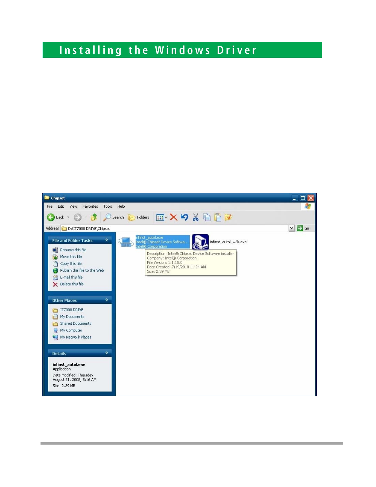
Driver List a. Intel Chipset driver
b. Intel Extreme Graphics driver
c. Intel 82562ET LAN driver
d. Realtek AC97 codec driver
e. TouchKit Touch Screen driver
Please always install the Intel Chipset driver first and restart the Windows system
before processing other driver’s installation.
Chipset Driver Installation
Insert the CD comes with the system into any USB external CD-ROM, select the CD driver and change directory to
“Chipset”.
5
Page 11
10
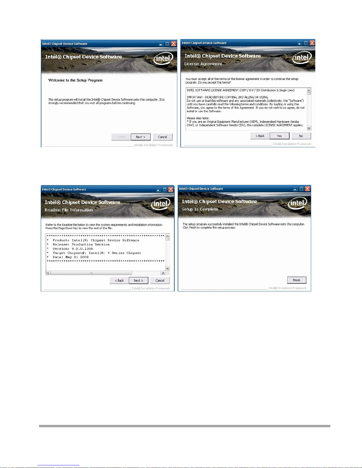
A. Click the “Next” button on the
Welcome window
B. Click the “Yes” button on the License
Agreement window
C. Click the “Next” button to continue
D. Click the “Finish” button
Page 12
11
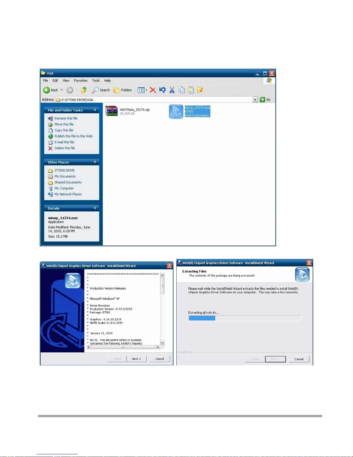
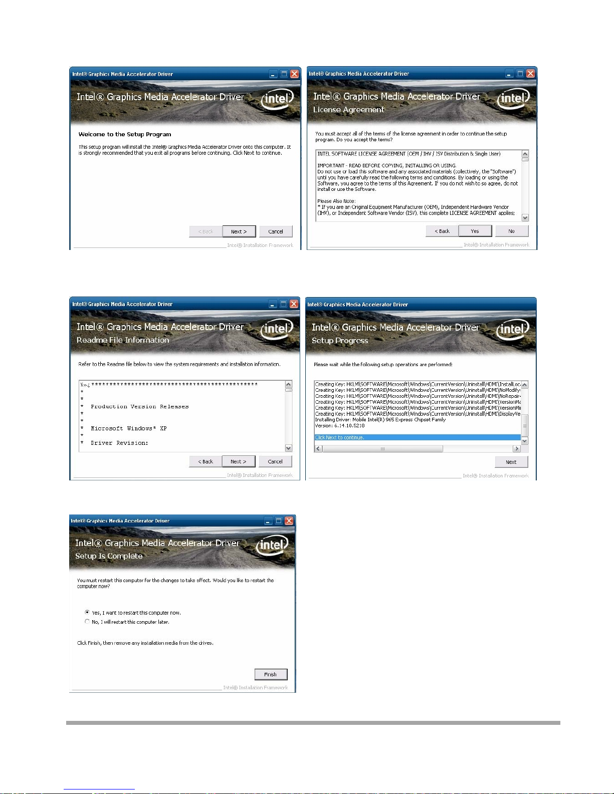
VGA Driver Installation
Select the CD directory to “VGA”
Page 13
12
A. Click the “Next” button on the
Welcome window
B. Click the “Yes” button on the License
Agreement window
C. Click the “Next” button to continue
D. Click the “Finish” button
Page 14
13
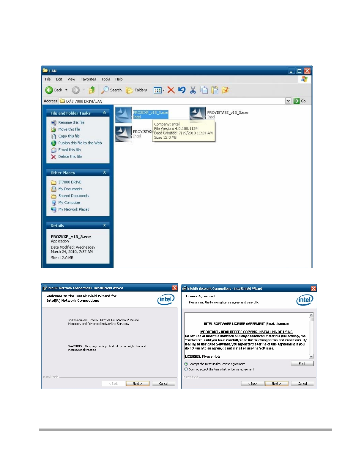
LAN Driver Installation
Select the CD directory to “LAN”
A. Click the “Next” button on the Welcome window
Page 15
14
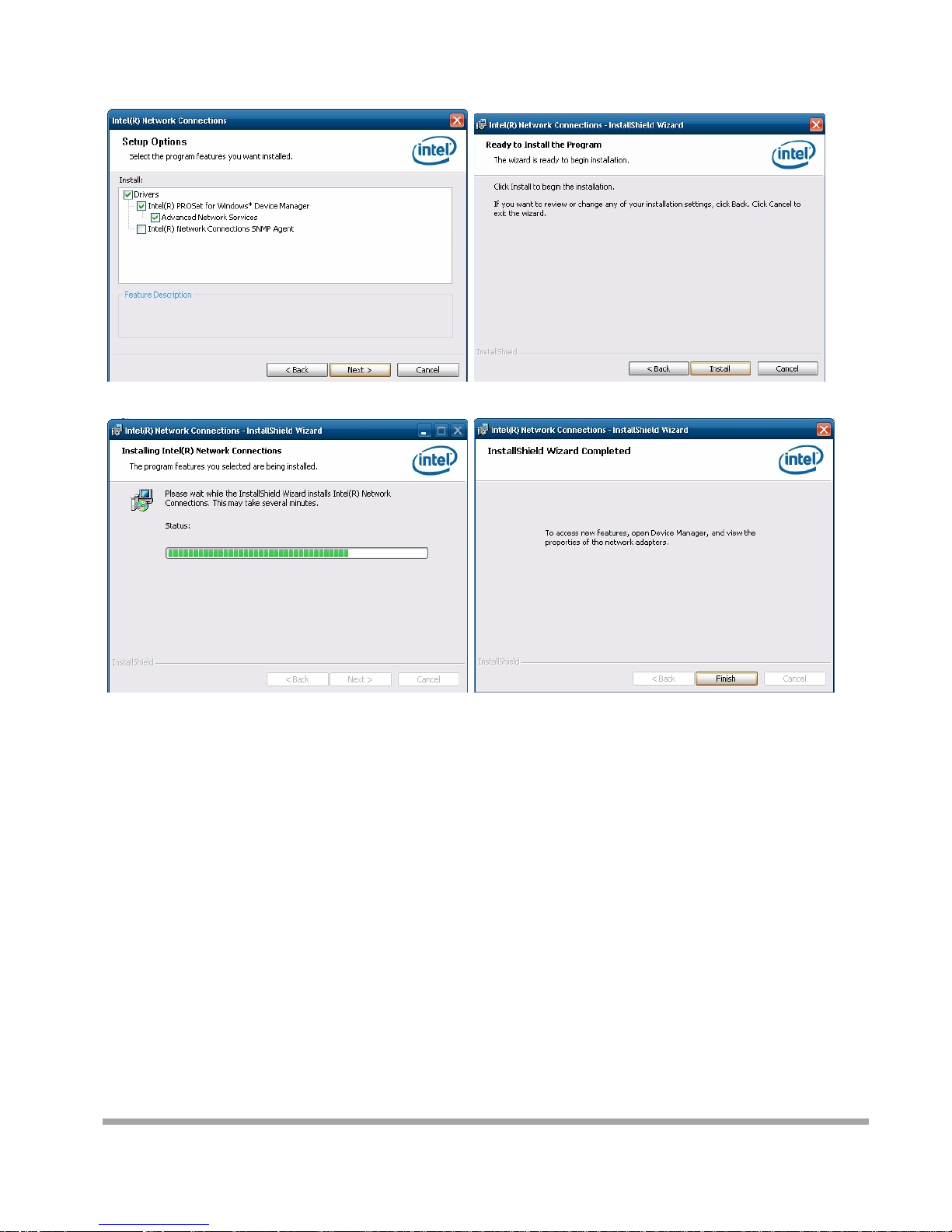
B. Click the “Finish” button
Page 16
15
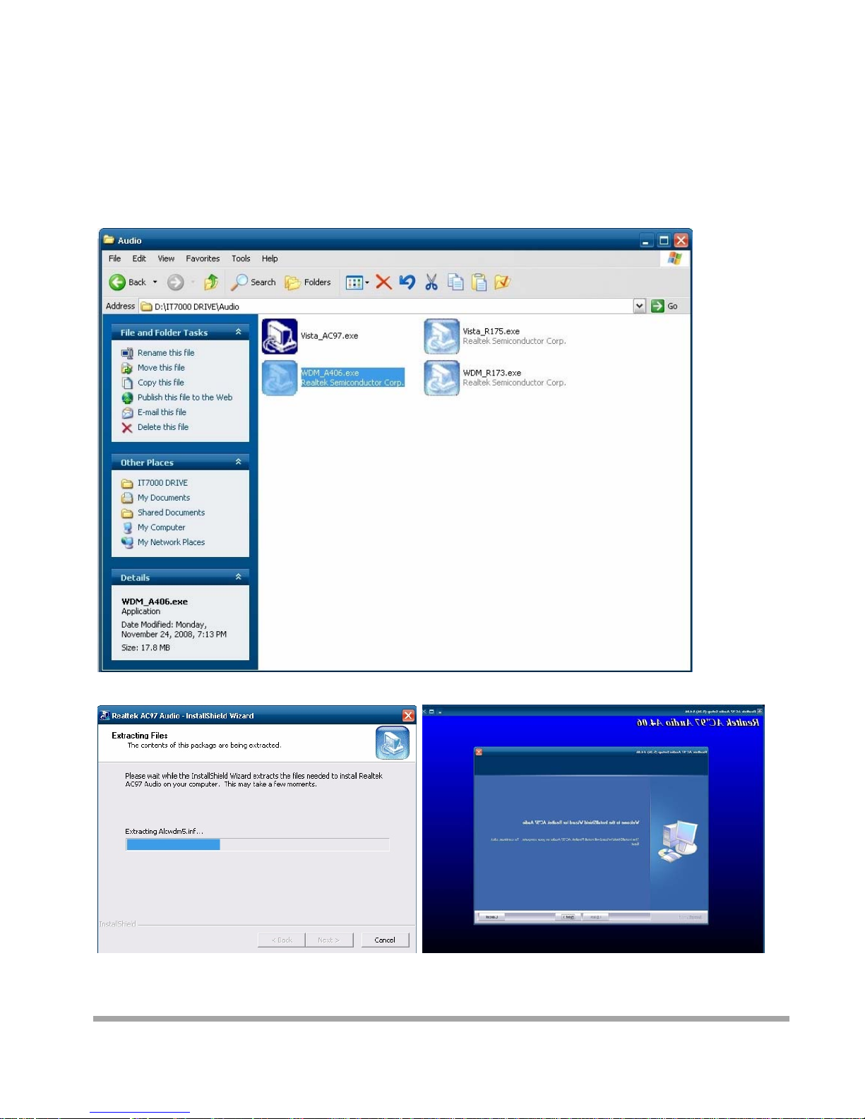
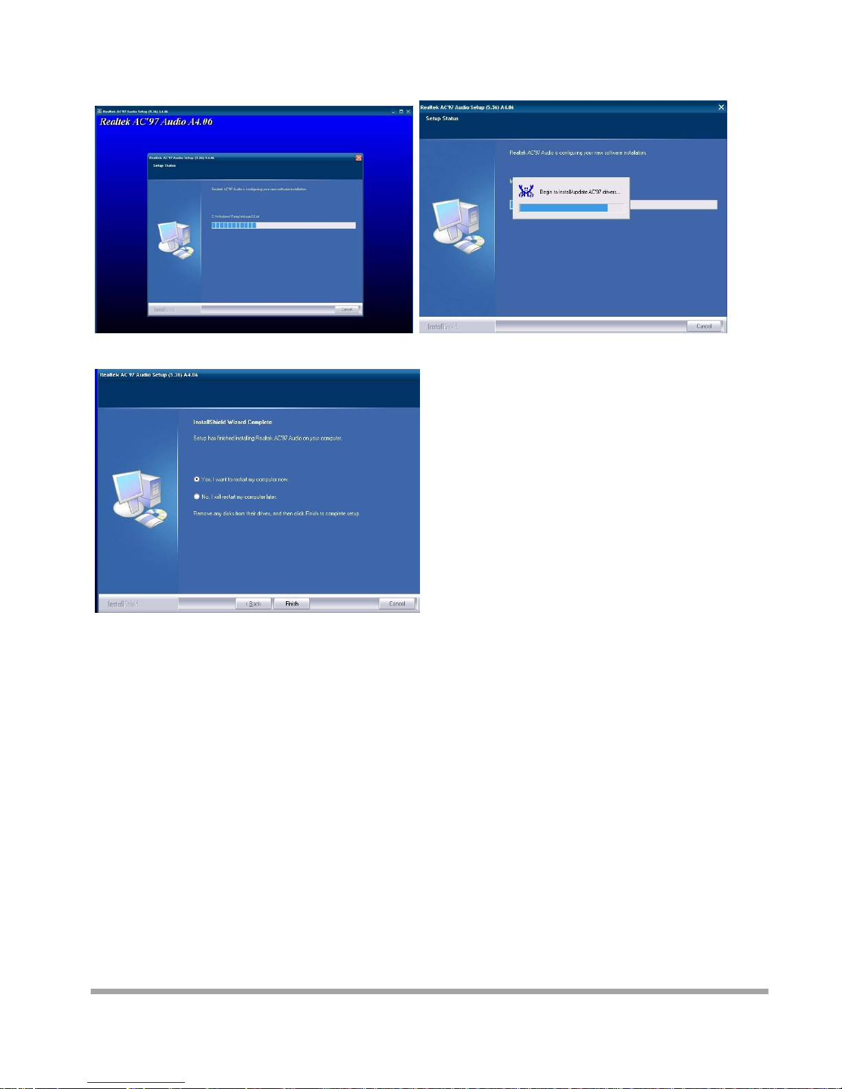
Audio Driver Installation
Select the CD directory to “Step 4 - Install Realtek AC97 codec Driver”
A. Click “NEXT”
Page 17
16
B. Click the “Finish” button
Page 18
17
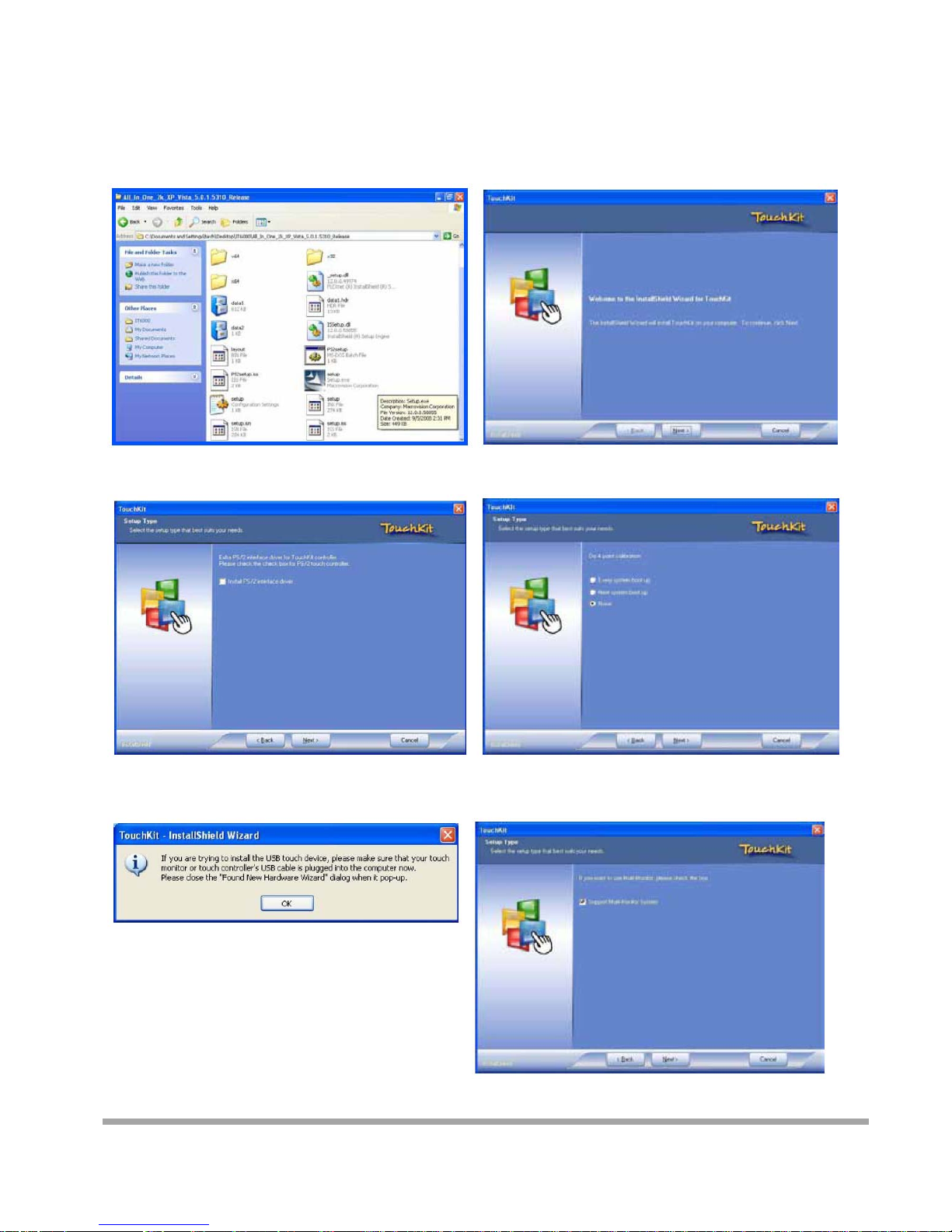
Touch Kit Touch Driver Installation
Select the CD directory to “TouchKit Driver”
A. Double click “SETUP” on the
My computer window
B. Click the “Next” button on the Welcome
window
C. Click “Next “button on the “Select Type”
window
D. Select “None” and Click “Next”
E. Click “ OK ”
F. Select “Support Multi-Monitor
System” Click “Next”
Page 19
18
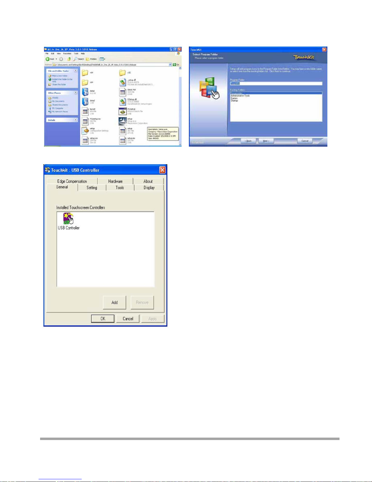
A. Double click “SETUP” on the my computer
window
B. Click the “Next” button on the Welcome
window
G. Install successful and restart your system
Page 20
19
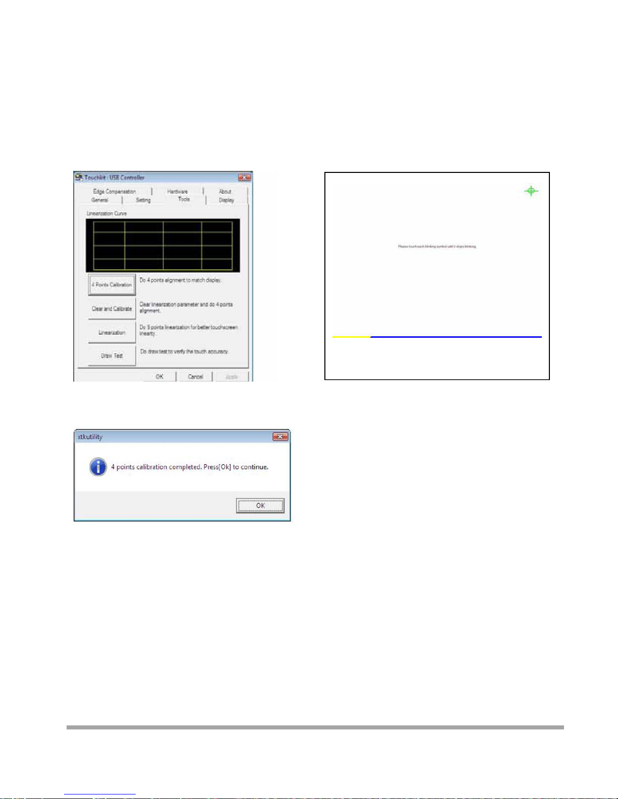
Four Points Calibration of the touch screen
Always perform the Four Points Calibration of the TouchKit program after your first
installation of the touch screen driver.
A. Select Tools then 4 Points Calibration.
B. Press the Green Blink Cross mark.
C. Press OK to continue.
Page 21
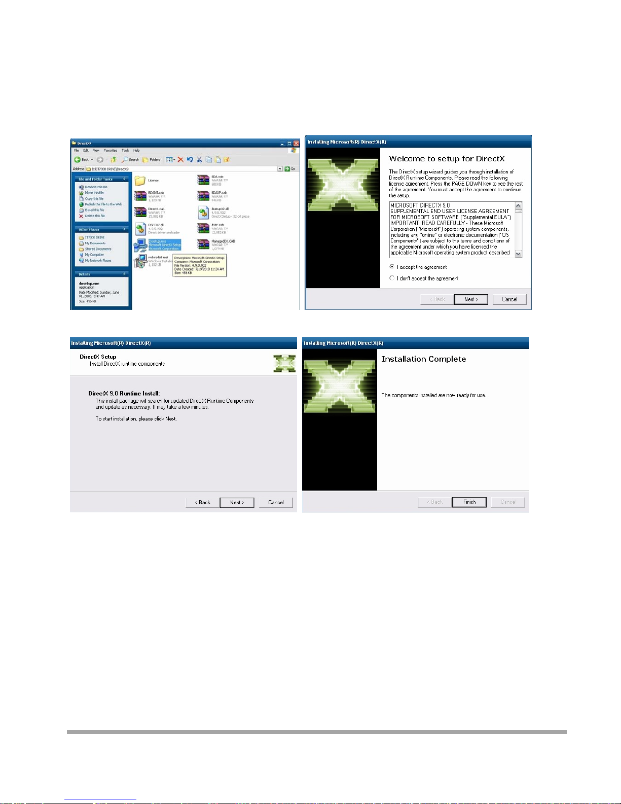
20
DirectX 9 Installation
Page 22
P
p
oyo
I
n
M
lease unpl
u
wer is al
w
u open a
n
stallin
g
other
b
FAN
Front
Board
g the AC
ays on aft
e
y part of t
h
Perip
h
oard L
a
CO
M
U
S
power of t
h
r the ada
p
e system.
erals
C
yout C
5US
B
L
e adapter
ter is plug
g
onnec
t
ompon
e
LVD
AN
before op
e
ed in. It
m
ors &
J
nt Sid
e
SI
N
COM
1
ning any
p
ay cause
p
umper
s
V
S
A
/2/3
art of the
s
ermanent
settin
g
S
TA
/4
ystem. Si
n
damage t
o
s
6
SATAp
o
PS/2
ce the sta
n
your syst
e
wer
U
S
PW
21
dby
m when
B
Page 23
C
T
y
Sol
d
onnec
t
pe: DF1
3
Pin
1
3
5
7
9
er sid
e
or: CN
_
10-pin pit
Descri
p
5VSB
USB4N
/
USB4P
/
GND
GND
USB3
/
ch=1.25m
tion
6N
6P
4
VGA
Pin
D
2 5
4
U6 U8 G
10
N
LPT
escriptio
n
VSB
SB5N/7N
SB5P/7P
ND
/C
Audio MIC
22
Page 24
23
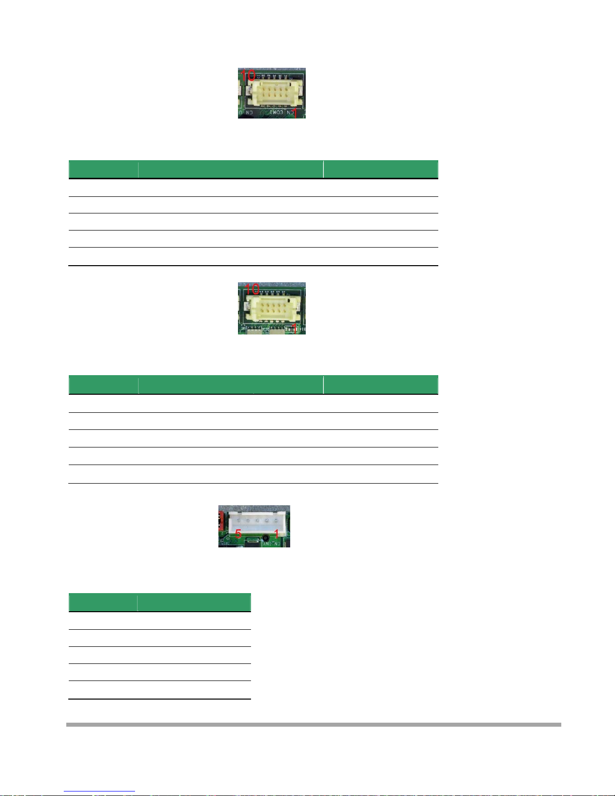
Connector: CN_COM1
Type: DF13 10-pin pitch=1.25mm
Pin Description Pin Description
1 MDCD1 2 MSIN1
3 MS01 4 MDTR1
5 GND 6 MDSR1
7 MRTS1 8 MCTS1
9 +12V 10 N/C
Connector: CN_COM2
Type: DF13 10-pin pitch=1.25mm
Pin Description Pin Description
1 MDCD1/2 2 MSIN1/2
3 MS01/2 4 MDTR1/2
5 GND 6 MDSR1/2
7 MRTS1/2 8 MCTS1/2
9 +5V 10 N/C
Connector: CN_INV
Type: 5-pin LVDS Power Header
Pin Description
1 +12V
2 CTLBKL
3 GND
4 GND
5 ENABKL
Page 25
24
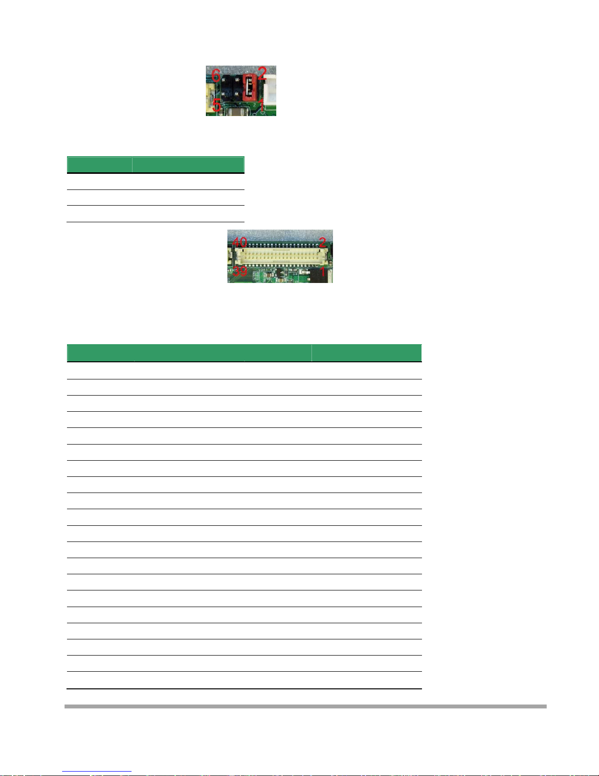
Connector: JVLCD
Type: 6-pin Power select Header
Pin Description
1-2
LCDVCC (3.3V)
3-4
LCDVCC (5V)
5-6
LCDVCC (12V)
Connector: CN_LVDS
Type: onboard 40-pin connector for LVDS connector
Connector model: HIROSE DF13-40DP-1.25V
Pin Description Pin Description
2 LCDVCC 1 LCDVCC
4 GND 3 GND
6 ATX0- 5 BTX0-
8 ATX0+ 7 BTX0+
10 GND 9 GND
12 ATX1- 11 BTX114 ATX1+ 13 BTX1+
16 GND 15 GND
18 ATX2- 17 BTX220 ATX2+ 19 BTX2+
22 GND 21 GND
24 ACLK- 23 BTX326 ACLK+ 25 BTX3+
28 GND 27 GND
30 ATX3- 29 BCLK32 ATX3+ 31 BCLK+
34 GND 33 GND
36 DDCPCLK 35 N/C
38 DDCPDATA 37 N/C
40 N/C 39 N/C
Page 26
25
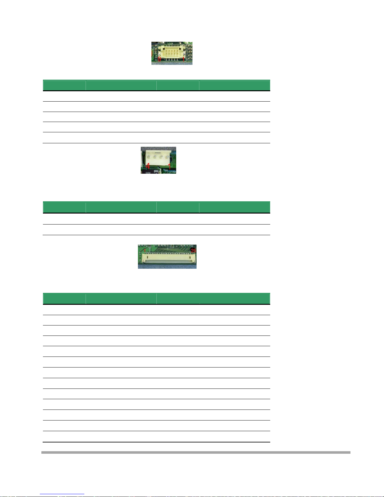
Connector: CN_JFRNT
Type: DF13 10-pin pitch=1.25mm
Pin Description Pin Description
1 PWRBT- 2 PWRBT-
3 LANLED- 4 LANLED+
5 HDLED 6 HDLED+
7 PWRLED 8 PWRLED+
9 Reset+ 10 Reset-
Connector: DC_OUT
Type: 4-pin connector for +5V/+12V output
Pin Description Pin Description
1 +12V 2 Ground
3 Ground 4 +5V
Connector: CN_LPT
Type: DF14 25-pin pitch=1.25mm
Pin Description Pin Description
1 -PSTB 2 AFD
3 PRD0 4 ERR
5 PRD1 6 INIT
7 PRD2 8 SLIN
9 PRD3 10 GND
11 PRD4 12 GND
13 PRD5 14 GND
15 PRD6 16 GND
17 PRD7 18 GND
19 ACK 20 GND
21 BUSY 22 GND
23 PE 24 GND
25 SLCT
Page 27
26
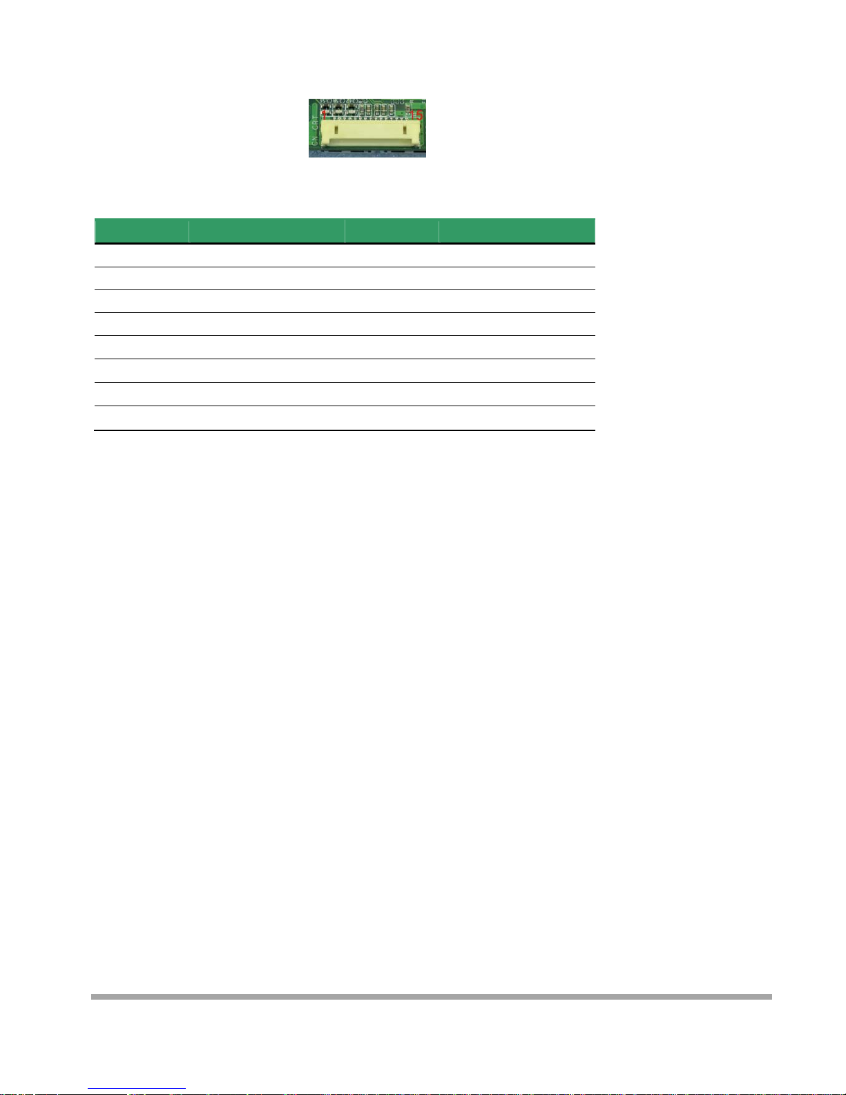
Connector: CN_CRT
Type: DF14 25-pin pitch=1.25mm
Pin Description Pin Description
1 BR 2 5VSB
3 BG 4 GND
5 BB 6 N/C
7 N/C 8 CDA
9 GND 10 HSYNC
11 GND 12 VSYNC
13 GND 14 CLK
15 GND
Page 28
C
A
B
haract
e
. Control c
o
. U.S.A. fo
n
r Font
de set
t set
Table
7
27
Page 29
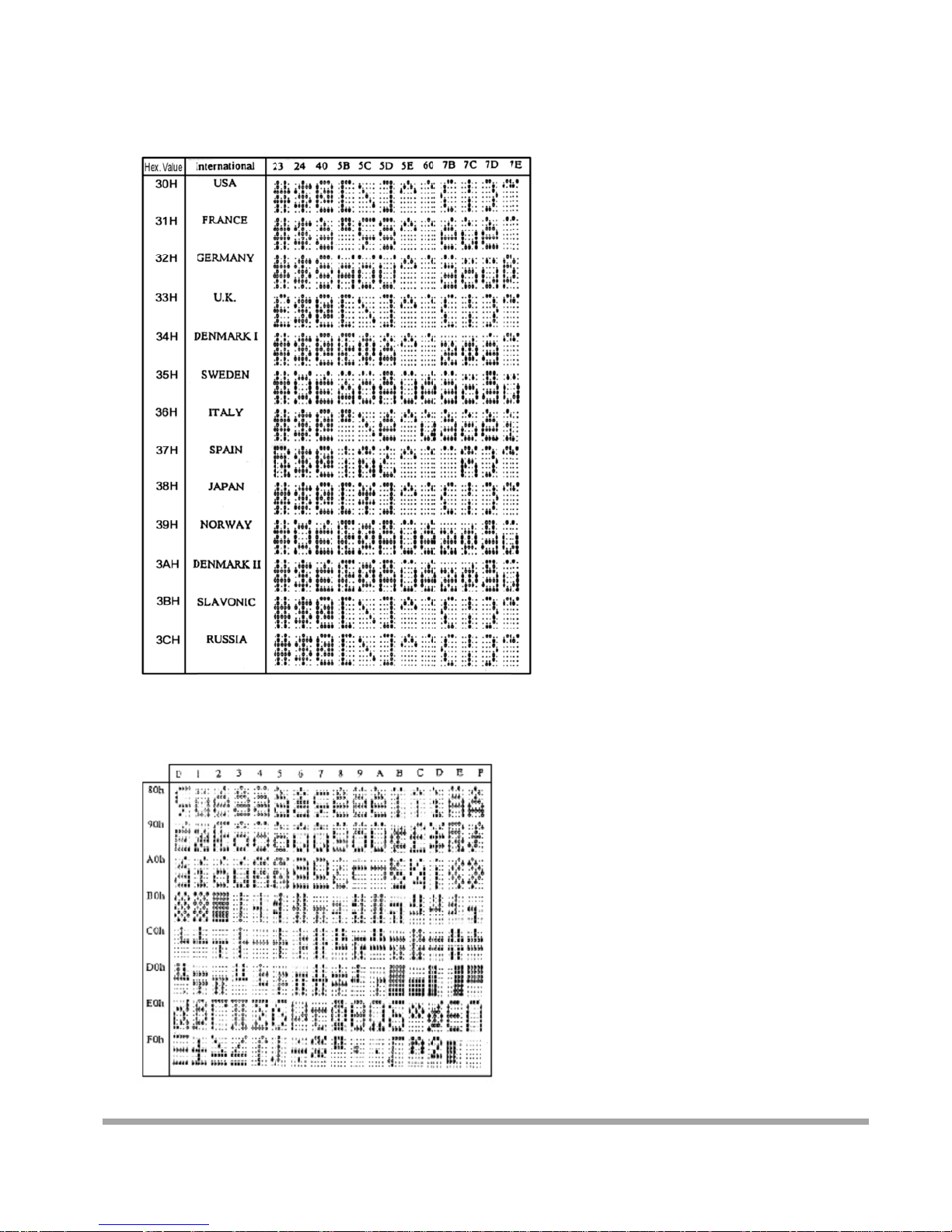
C
3
D
. Internatio
n
H: Stand
a
al charact
e
ASCII C
O
rd Europe
i
r selection
DE
nternational font set
28
Page 30
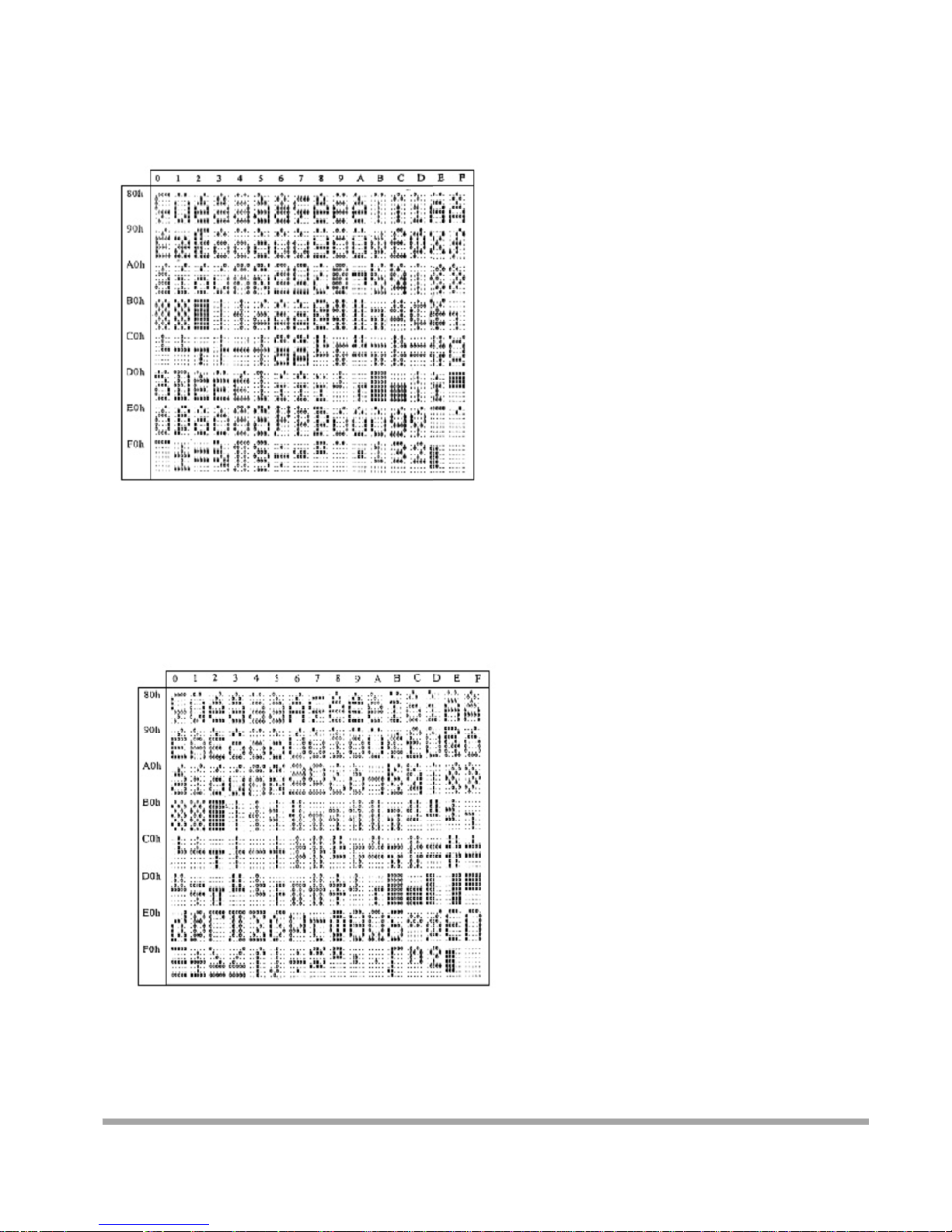
3
E
3
F
H: Multin
g
H: Portug
u
ual intern
a
ese intern
a
tional font
tional font
set
set
29
Page 31
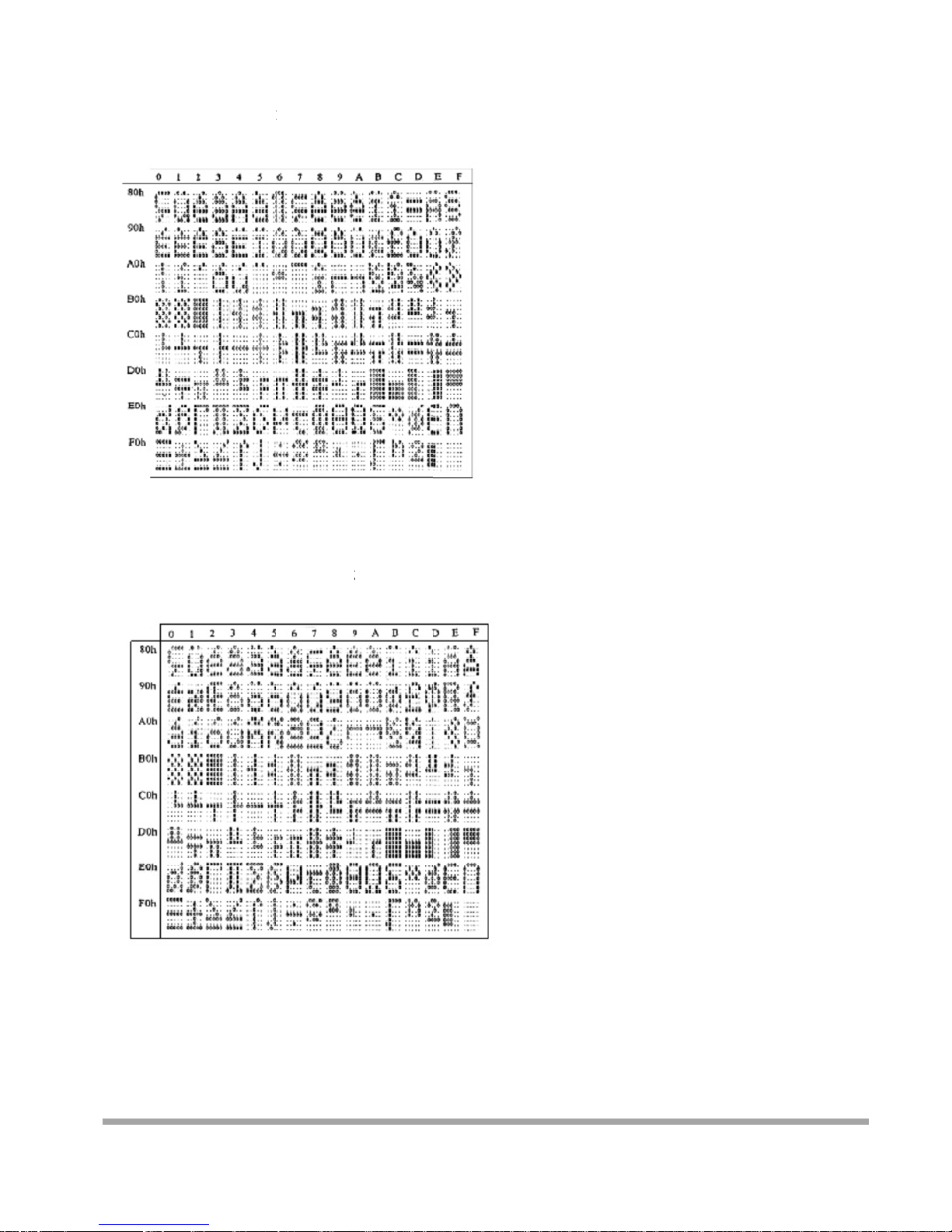
4
0
4
1
H: Canadi
a
H: NORD
I
n French i
n
C internat
i
ternationa
nal font se
t
font set
30
Page 32
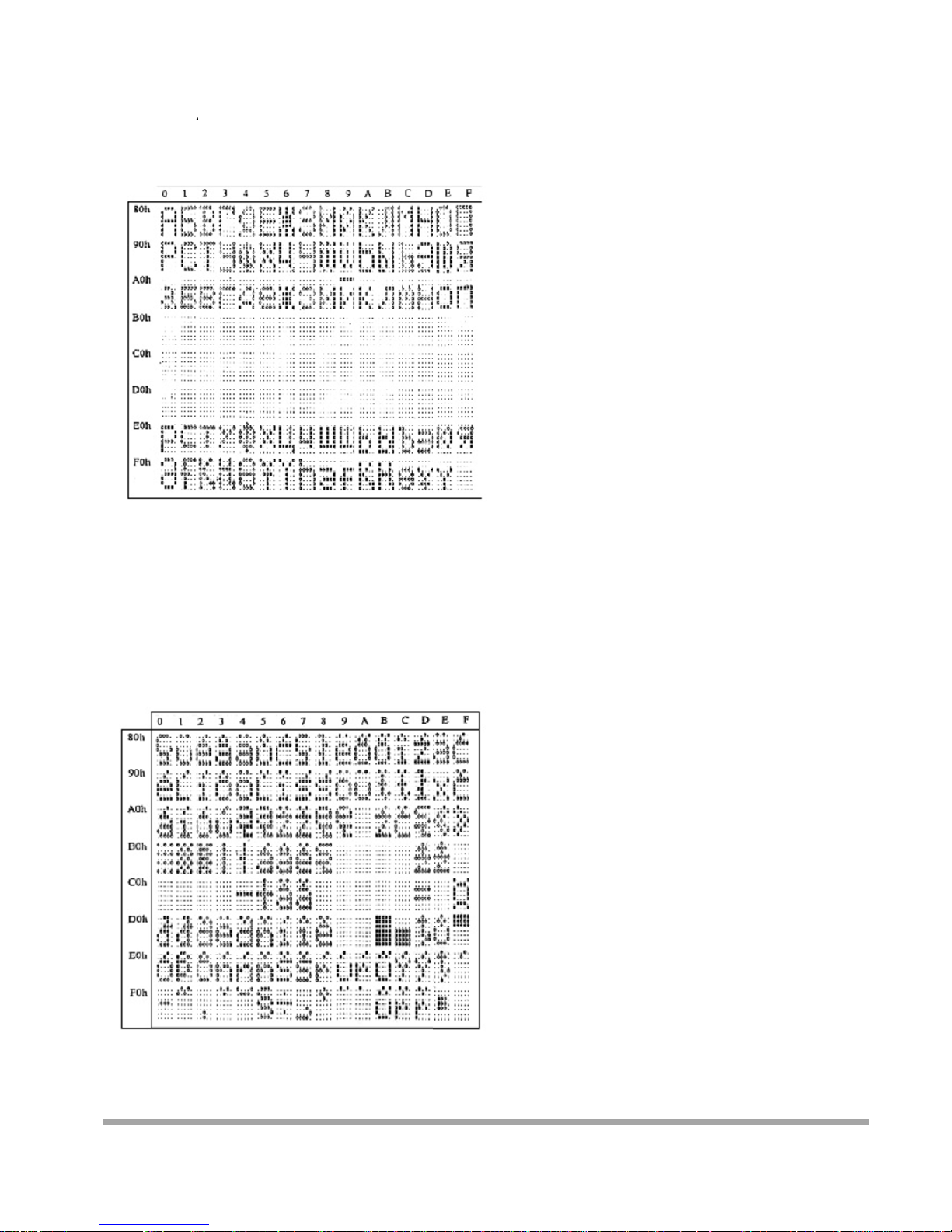
4
2
4
3
H: RUSSI
A
H: SLAV
O
font set
NIC Font set
31
Page 33
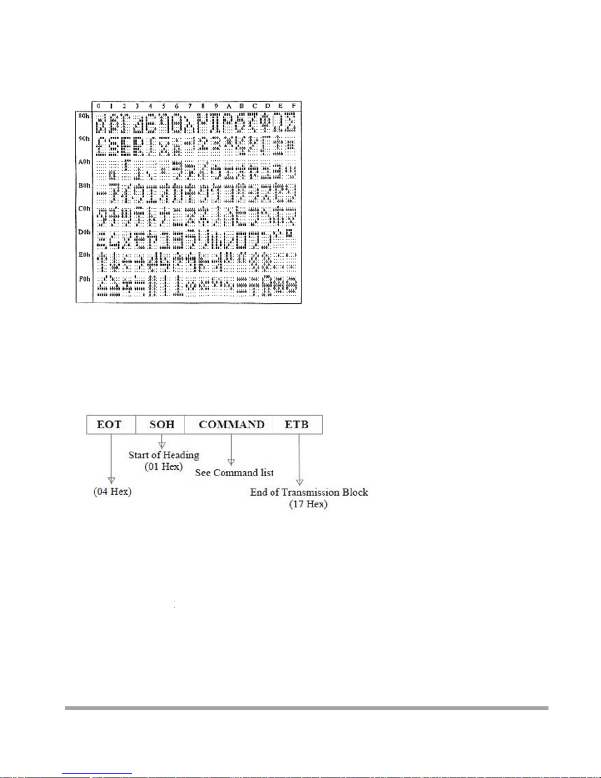
4
4
S
C
C
H: Kataka
n
ystem
C
ommand
F
ommand L
A. Se
t
a font set
omm
a
ormat
ist
Baud Rat
e
COMMAN
D
COMPUTE
R
ASCI
IByt
DISPL
A
ASCI
I
By
t
nds
: B
:EOT SOH '
B
(04H) (01H)(
4
e 1 1
Y: ACK
(06H)
e 1
' 'BAUD RAT
E
2H) (31H~37
H
1 1
(
' 'N' ETB
)(4EH)(17H)
1 1
or NACK if fa
i
(15H)
1
led)
32
Page 34
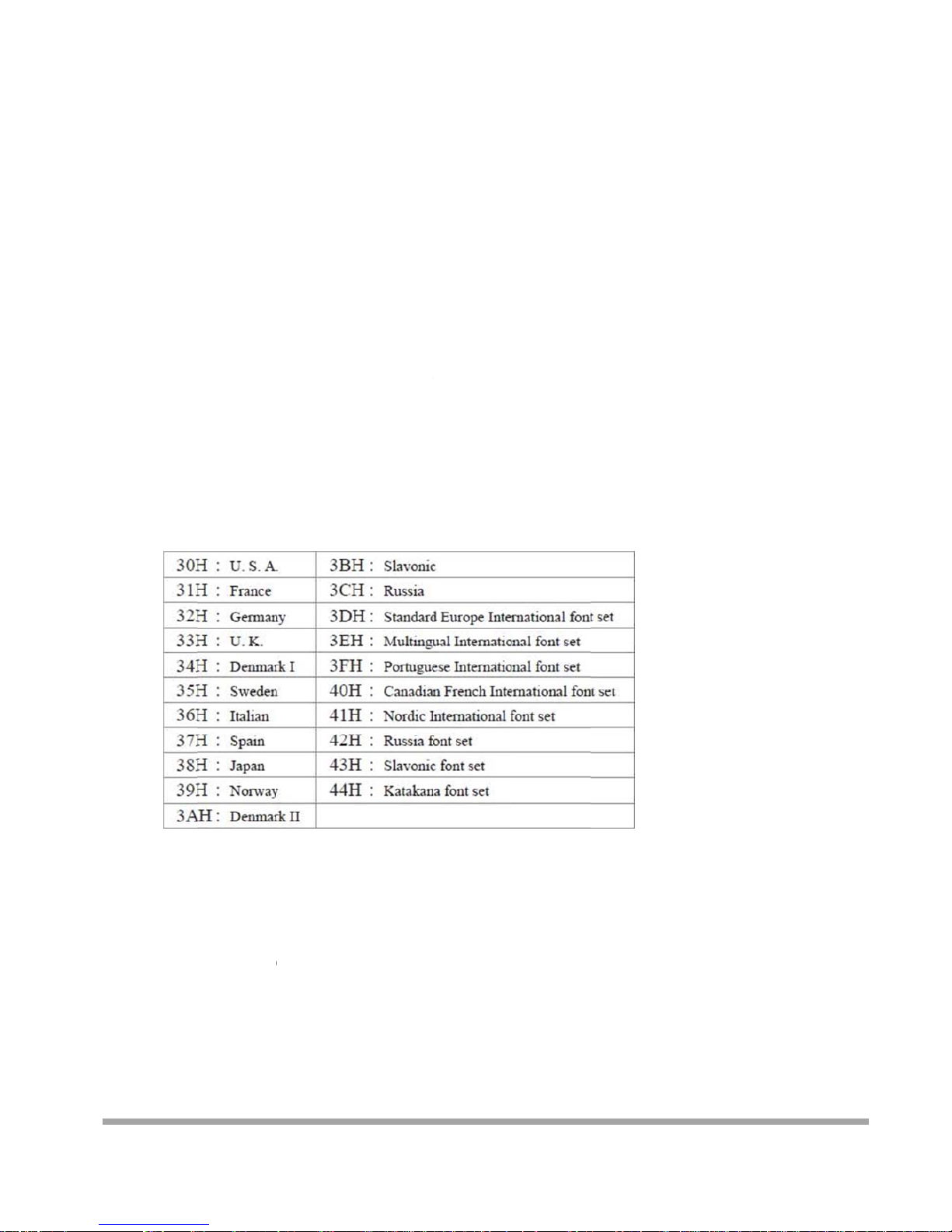
Note:
B. Se
l
Note :
C. Sa
v
(S
a
Note :
Baud rates
31H: 9600
32H: 4800
33H: 2400
34H: 1200
35H: 600
36H: 300
37H:1920
0
ect interna
t
COMMA
N
COMPUT
E
AS
C
By
t
DISPL
A
AS
CByt
International
e the curr
e
ve Demo vie
w
COMMA
N
COMPUT
E
AS
C
B
DISP
LAS
31H: Layer
1
ional code
t
D: I
R:EOT SO
H
II(04H)(01H
)
e 1 1
Y: ACK
II (06H)
e 1
Character C
o
nt view me
s
data)
D: S
R:EOT SO
H
II(04H)(01
H
yte 1
1
AY: ACK
CII (06H)
Byte 1
/ 32H: Laye
r
able
'I' 'CHAR' E
(49H)(30H~
4
1 1
(or N
A
(
de
sage
'S' 'Layer' E
T
)(53H)(31H
~
1
1
(or N
A
(
2 / 33H: La
y
TB
4H)(17H)
1
CK if failed
15H)
1
B
33H)(17H)
1
CK if failed)
15H)
1
er 3
)
33
Page 35

34
D. Set cursor position
COMMAND: P
COMPUTER: EOT SOH 'P' 'Position' ETB
ASCII (04H) (01H) (50H) (31H~58H) (17H)
Byte 1 1 1 1 1
DISPLAY: ACK (or NACK if failed)
ASCII (06H) (15H)
Byte 1 1
Note: The cursor can be set to the position from 1 to 40
Position 1 means the upper left corner position.
Position 20 means the upper right corner position.
Position 21 means the lower left corner position.
Position 40 means the lower right corner position.
E. Clear display range
COMMAND: C
COMPUTER: EOT SOH 'C' 'START' 'END' ETB
ASCII (04H)(01H)(43H)(31H~58H)(31H~58H)(17H)
Byte 1 1 1 1 1
DISPLAY: ACK (or NACK if failed)
ASCII (06H) (15H)
Byte 1 1
Note: Some part of the current view messages can be
cleared by this COMMAND. It can start clearing
between position 1 and position 40.
F. Display the saved DEMO message
COMMAND: D
COMPUTER: EOT SOH 'D' 'Layer' 'Mode' ETB
ASCII (04H)(01H)(44H)(31H~37H)(31H~33H)(17H)
Byte 1 1 1 1 1
DISPLAY: ACK (or NACK if failed)
ASCII (06H) (15H)
Byte 1 1
Note:
a) There are three layers of saved view messages as described on COMMAND "S"
b) There are two modes of display:
Mode 1 is running the saved messages from right to left, which is a horizontal scroll mode.
Mode 2 is running the saved messages from the lower line to the upper line, which is a vertical scroll mode.
c) For display layers:
Page 36
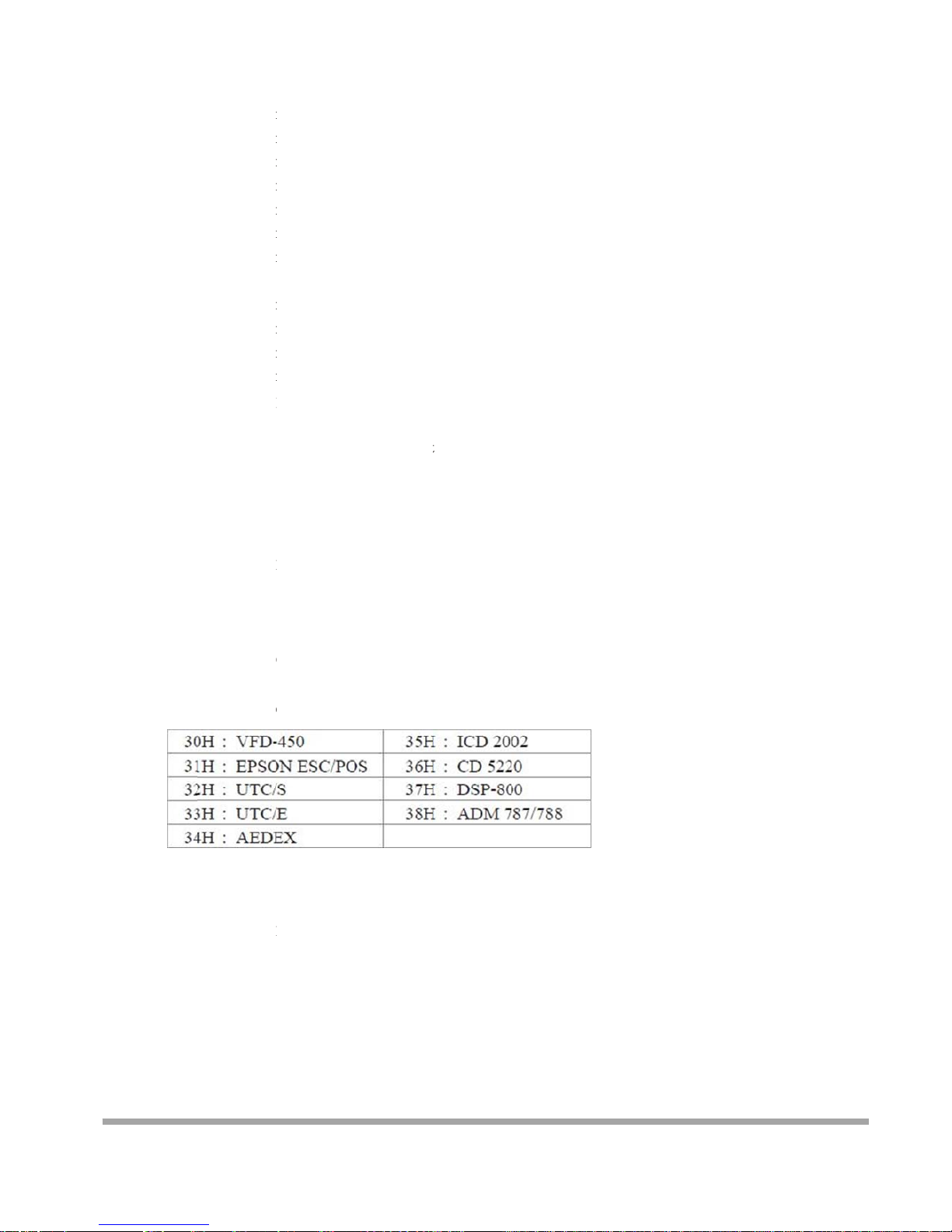
d) For
e) An
y
G. Se
l
Note:
H. Se
t
select 31H
m
select 32H
m
select 33H
m
select 34H
m
select 35H
m
select 36H
m
select 37H
m
display mode
s
select 31H
m
select 32H
m
select 33H
m
For this De
m
37H for dis
p
layer 1+ la
y
new message
display fun
c
ect the Co
m
COMMAN
D
COMPUTE
R
ASCI
IBy
DISPL
AASC
B
Command M
o
all default
COMMAN
D
COMPUTE
R
ASCI
IByt
eans display
eans display
eans display
eans display
eans display
eans display
eans display
,
eans display
eans display
eans display
o display fu
n
p
laying layers
er 2 + layer 3
from the com
p
tion and DSP
mand Mo
d
: M
: EOT SOH '
M
(04H) (01H)
(
te 1 1
Y: ACK
II (06H)
yte 1
des Selectio
n
: X
: EOT SOH '
X
(04H) (01H)
(
e 1 1
the message s
the message s
the message s
the message s
the two mess
a
the two mess
a
all the messa
g
the message
w
the message
w
the message
w
ction, you m
u
and select 33
H
with both Mo
d
uter would st
would displa
y
e
' 'Mode' ETB
4DH)(30H~3
8
1 1
(or N
A
(
1
' ETB
58H) (17H)
1 1
aved on layer
aved on layer
aved on layer
aved on layer
ges saved on
l
ges saved on
l
es saved on l
a
ith Mode 1.
ith Mode 2.
ith Mode 1+
M
st have saved
for displayi
n
e 1 + Mode
2
op this Demo
that new me
s
H) (17H)
1
CK if failed)
5H)
1
1.
2.
1+ layer2.
3.
ayer 1 + laye
r
ayer 2 +layer
yer 1 +layer
2
ode 2.
the message b
g modes, DS
P
displaying m
o
sage from the
3.
3.
+ layer 3.
COMMAN
D
would displa
y
des.
computer.
"S" previou
s
all the three
ly, For examp
messages sav
e
35
le, select
d on
Page 37
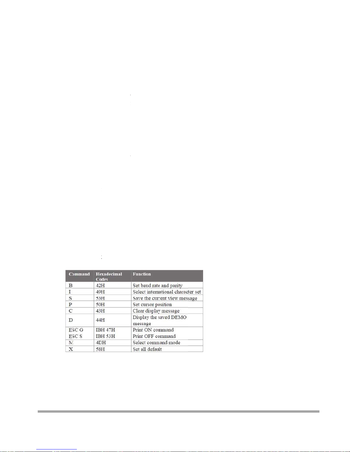
Tr
C
T
h
ansmissio
n
Each
A
Note:
omm
a
e command
m
Mode
Mode
Mode
Mode
Mode
Mode
Mode
Mode
Mode
Mod
e
method
SCII charac
t
1 start bit
8 data bits
1 stop bit
No parity
You may
g
RS-232C
c
nd M
o
odes can be
0: Default
1: EPSON E
s
2: UTC Stan
d
3: UTC Enha
n
4: AEDEX
5: ICD 2002
6: CD 5220
7: DSP-800
8: ADM 787
/
0: Defaul
t
er is transmit
t
enerate your
o
ommunicatio
n
des
selected wit
h
c/POS
ard
nced
788
ed with
wn applicati
protocols a
n
the Demo S
o
on software t
o
d the SOFT
W
ftware.
run the disp
l
ARE CON
T
ay according
ROL inform
a
to the standa
r
tion listed o
n
d
this chapter.
36
Page 38
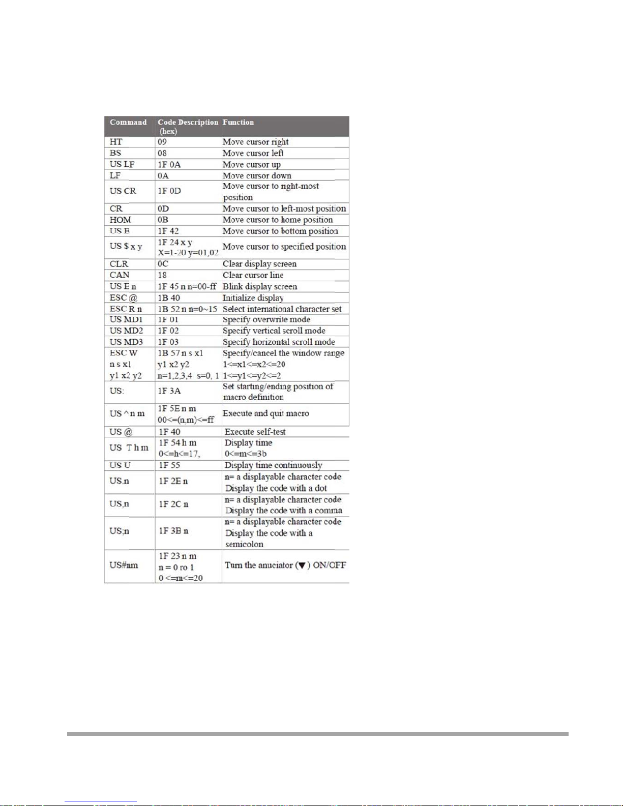
Mode 1: EPSON Esc/POS mode
37
Page 39
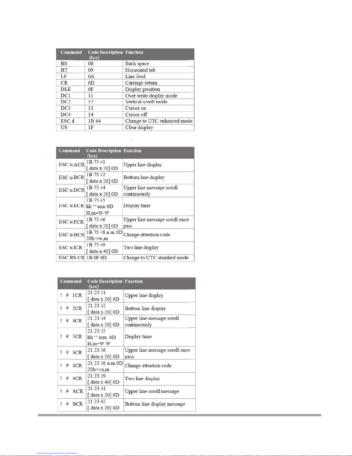
Mod
e
Mod
e
Mod
e
2: UTC S
t
3: UTC e
n
4: AEDE
X
andard mo
d
hanced m
o
mode
e
de
38
Page 40
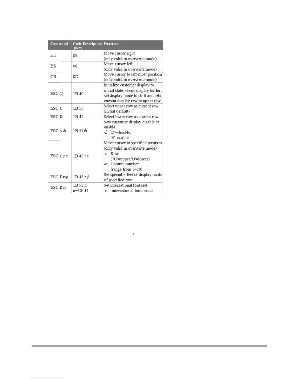
Mod
e
REM
A
5: ICD 20
RK)* Usin
g
r
554
Φ
3
33333
02 mode
command "
E
8= all rows
5= upper ro
w
4= lower ro
w
special funct
i
0= shift mo
d
1= rotation
m
2= blink mo
d
3= clear this
4= overwrit
e
5= vertical
m
SC E r Φ", t
h
on, the value
e (default)
ode
e
row and swit
c
mode
ode
e value of
pa
is one of
h to shift m
o
rameter:
de
39
Page 41
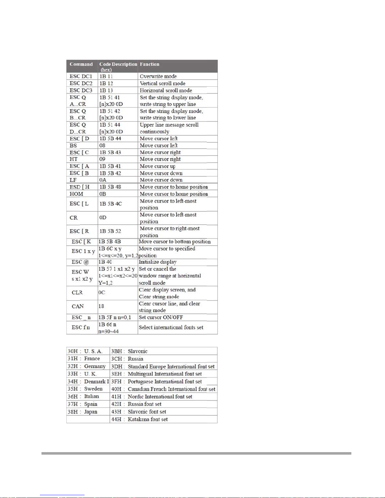
Mode 6: CD 5220 standard mode
40
Page 42
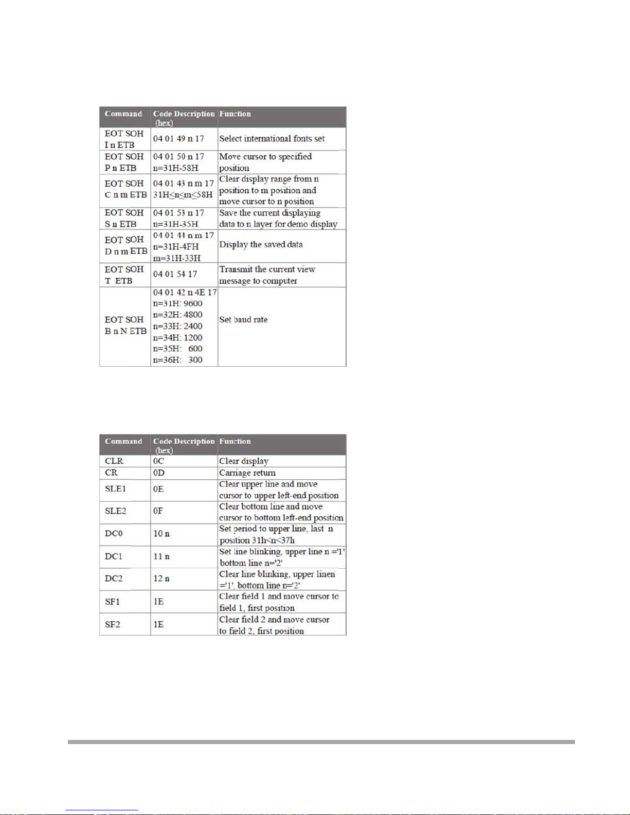
Mod
e
Mod
e
7: DSP-8
0
8: ADM
7
0 mode
87/788 mode
41
Page 43
42
CE MARK
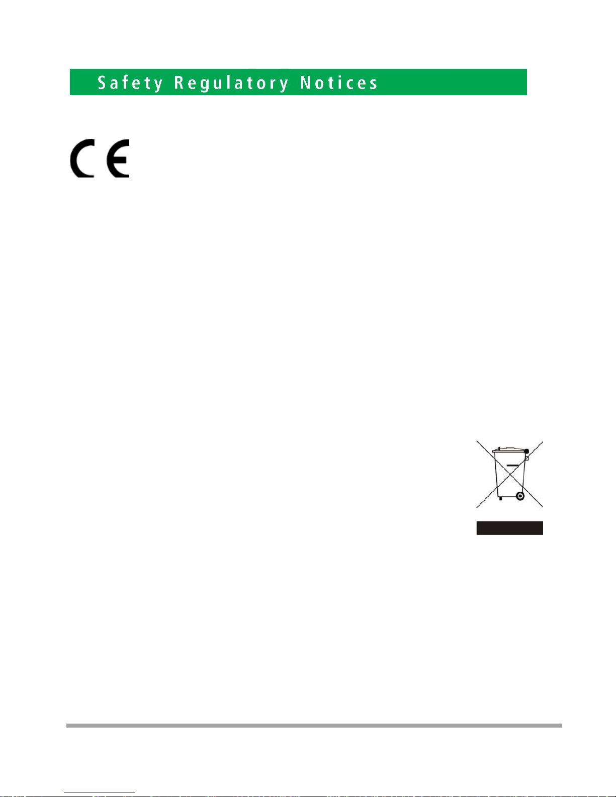
This device compiles with the requirements of the EEC directive 89/336/EEC with regard to
“Electromagnetic compatibility” and 73/23/EEC “Low Voltage Directive”
FCC This device complies with part 15 of the FCC rules. Operation is subject to the following two
conditions:
(1)This device may not cause harmful interference.
(2)This device must accept any interference received, including interference that may cause
undesired operation.
CAUTION ON LITHIUM BATTERIES
There is adapter of explosion if the battery is replaced incorrectly. Replace only with the same or equivalent type
recommended by the manufacturer. Discard used batteries according to the manufacturer’s instructions.
LEGISLATION AND WEEE SYMBOL
2002/96/EC Waste Electrical and Electronic Equipment Directive on the treatment, collection,
recycling and disposal of electric and electronic devices and their components.
The crossed dustbin symbol on the device means that it should not be disposed of with other
household wastes at the end of its working life. Instead, the device should be taken to the
waste collection centers for activation of the treatment, collection, recycling and disposal
procedure.
To prevent possible harm to the environment or human health from uncontrolled waste disposal,
please separate this from other types of wastes and recycle it responsibly to promote the sustainable reuse
of material resources.
Household users should contact either the retailer where they purchased this product, or their local
government office, for details of where and how they can take this item for environmentally safe recycling.
Business users should contact their supplier and check the terms and conditions of the purchase contract.
This product should not be mixed with other commercial wastes for disposal.
 Loading...