

Page 1
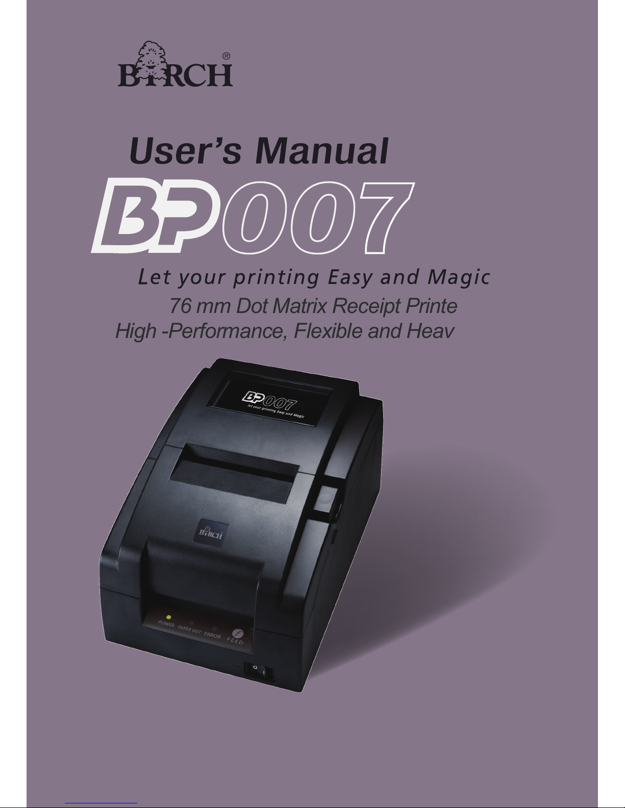
76 mm Dot Matrix Receipt Printer
High -Performance, Flexible and Heavy Duty
Page 2

BP-007 User’s Manual
- i -
Important Safety Instructions
Read all of these instructions carefully and thoroughly and save them for later reference. The unauthorized
operation may lead to error or accident. Manufacturer will not answer for any problems which lead by
unauthorized operations.
1. Follow all warnings and instructions in the manual as well as marked on the product.
2. Don’t touch the thermal print head with your hand and other solid object at any moment to avoid your
body burned or the thermal head damaged.
3. Be careful the dentate cutter when you are installing the paper.
4. Unplug this product from the power outlet before cleaning. Do not use liquid or aerosol cleaners. Use a
damp cloth for cleaning.
5. Please don’t use the printer near the water.
6. Do not place this product on an unstable cart, stand or table. The product may fall, causing serious
damage to you or the product.
7. Slots and openings on the cabinet and the back or bottom are provided for air ventilation. To ensure
reliable operation of the product and to protect it from overheating, do not block or cover these
openings. The openings should never be blocked by placing the product on a bed, sofa, rug or other
similar surface. This product should never be placed near or over a radiator or heater. This product
should not be placed in a built-in installation or kiosk stand unless proper ventilation is provided.
8. This product should never be placed near or over a radiator or heat origin, and should avoid of direct
sunshine.
9. Do not locate this product where the cord will be walked on. When the cord or the plug is mangled,
please stop using and get a new one replaced. Make sure the old one is far away from the printer, so it
can avoid someone who does not know the inside story getting damage.
10. Do not use in locations subject to high humidity or dust levels. Excessive humidity and dust may cause
equipment damage or fire.
11. Never push objects of any kind into this product though cabinet slots as they may touch dangerous
voltage dots or short out parts.
12. Don’t remove the printer’s out-cover and repair the printer. When needed, call or take it to the
professional.
13. To ensure safety, please unplug this product prior to leaving it unused for an extended period. The wall
outlet you plan to connect to should be nearby and unobstructed.
14. This device complies with Part 15 of the FCC Rules.
Operation is subject to the following two conditions:
(1) This device may not cause harmful interference.
(2) This device must accept any interference received, including interference that may cause undesired
operation.
The manufacturer is not responsible for any radio or TV interference caused by unauthorized
modifications to this equipment. Such modifications could void the user's authority to operate the
Page 3

BP-007 User’s Manual
- ii -
equipment.
15. Unplug this product from the power outlet and leave servicing to qualified service personnel under the
following conditions:
When the power cord or plug is damaged or frayed.
a) If liquid has been spilled into the product.
b) If the product has been exposed to rain or water.
c) If the product does not operate normally when the operating instructions are followed. Adjust only
those controls that are covered by the operating instructions since importer adjustment of other
controls may result in damage and will often require extensive work by a qualified technician to
restore the product to normal operation.
d) If the product has been dropped or the cabinet has been damaged.
e) If the product exhibits a distinct change in performance, indicating a need for service.
Warning: In order to ensure the printer life, strictly prohibit printing full line full black
exceeding 2 CM.
Notice: The contents of this manual are subject to change without notice.
*All the parts of the printer can be recycled. When it is abandoned, we can call it back freely.
Please contact us when you abandon it.
Page 4

BP-007 User’s Manual
- iii -
Table of Contents
Important Safety Instructions
..................................................................................................................... i
Chapter 1 Introduction
............................................................................................................................... 1
1.1 Features..............................................................................................................................................1
1.2 Application
...........................................................................................................................................1
1.3 Main Parts of the
Printer......................................................................................................................2
Chapter 2 Printer Inst
allation.....................................................................................................................3
2.1 Unpacking and Checki
ng ....................................................................................................................3
2.2 Removing the Protect
ive Materials......................................................................................................3
2.3 Connecting Computer or Other Equipments
.......................................................................................3
2.3.1 Connecting the Cash Drawer Cable
.............................................................................................3
2.3.2 Connecting the Par
allel Cable......................................................................................................4
2.3.3 Connecting the USB Cable
...........................................................................................................4
2.3.4 Connecting the Seri
al Cable.........................................................................................................5
2.3.5 Connecting the Ethernet Cable
.....................................................................................................5
2.4 Connecting the Power Cord
................................................................................................................6
2.5 Installing the Ribbon Cartridge
............................................................................................................6
2.6 Installing the Driv
er .............................................................................................................................7
2.7 Installing Bluetooth Interface Driv
er ..................................................................................................10
2.8 Network Settings
...............................................................................................................................13
2.8.1 Connecting Printer
......................................................................................................................13
2.8.2 Setting IP Address
......................................................................................................................13
2.9 Wi-Fi Set
ting......................................................................................................................................15
2.9.1 Connect to the Printer, Run the W
iFiConfig Software.................................................................16
2.9.2 Set Wi-Fi Param
eters .................................................................................................................17
2.9.3 Checking Wi-Fi Param
eters........................................................................................................18
2.9.4 Recover the Default Sett
ing........................................................................................................19
2.10 Installing Printer Network Driver
......................................................................................................19
Chapter 3 Control Panel...........................................................................................................................26
3.1 Control Panel
....................................................................................................................................26
3.1.1 Indicat
or LEDs............................................................................................................................26
3.1.2 Function Keys
.............................................................................................................................26
3.2 Printer Parameter Set
tings................................................................................................................26
3.2.1 Current Settings of t
he Printer Parameter...................................................................................26
3.2.2 Printer Setting Desc
riptions........................................................................................................27
3.2.3 Parameter Settings
.....................................................................................................................28
3.3 Self-Test
Function .............................................................................................................................29
Chapter 4 Installing Paper........................................................................................................................31
Chapter 5 Specifications
..........................................................................................................................32
5.1 Basic Specifications .......................................................................................................................... 32
5.2 Interface
............................................................................................................................................33
5.2.1 Cash Drawer Interface
................................................................................................................33
5.2.2 Parallel Interface
.........................................................................................................................34
Page 5

BP-007 User’s Manual
- iv -
5.2.3 USB Interface.............................................................................................................................36
5.2.4 Serial I
nterface ...........................................................................................................................37
5.2.5 Ethernet Interface
.......................................................................................................................38
5.3 Auto-cutter S
pecification....................................................................................................................39
Chapter 6 Troubleshooting and Maintenance
........................................................................................40
6.1 Clean the Printer
...............................................................................................................................40
6.2 Problems and Solutions
....................................................................................................................40
Chapter 7 Command Co
de Summary .....................................................................................................42
7.1 General ............................................................................................................................................. 42
7.2 Explanation of Command
..................................................................................................................42
Appendix Commands L
ist .......................................................................................................................54
Page 6

BP-007 User’s Manual
- 1 -
Chapter 1 Introduction
1.1 Features
BP-007 series products are developed by our corporation in order to fulfill different requirements and
using environments. BP-007 series printers can be configured with parallel interface, USB interface,
serial interface, USB interface + Ethernet interface, Bluetooth or USB interface + Wi-Fi.
Interface:
BP-007 series products are configured with a cash drawer interface, you can choose one of the
following data interfaces when purchasing this product:
Model Interface Cable Color
BP-007BP Parallel interface Parallel interface cable Black
BP-007BU Serial interface USB interface cable Black
BP-007BR USB interface Serial interface cable Black
BP-007BN USB interface + Ethernet interface Ethernet interface cable Black
BP-007BT Bluetooth USB interface cable Black
BP-007BF USB interface + Wi-Fi USB interface cable Black
BP-007WP Parallel interface Parallel interface cable White
BP-007WU Serial interface USB interface cable White
BP-007WR USB interface Serial interface cable White
BP-007WN USB interface + Ethernet interface Ethernet interface cable White
BP-007WT Bluetooth USB interface cable White
BP-007WF USB interface + Wi-Fi USB interface cable White
Note: Please contact the local dealer to change the interface with added expense if needed.
1.2 Application
y Embedded installation and preprinting common bill printing market
y Embedded installation and trilogy common bill printing market
y Can be applied to tax-controlled cash register for invoice printing
y Can be applied to electronically billing machine for invoice printing
y Can be applied to self-service terminal for invoice printing or applied to other preprinting bill printing
Page 7
BP-007 User’s Manual
- 2 -
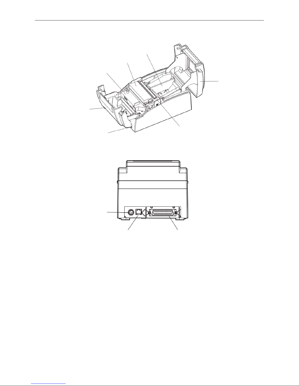
1.3 Main Parts of the Printer
Note: According to specific interface standards
Figure 1-1 Main parts of printer (Front view)
Fi
g
ure 1-2 Main parts of printe
r
(
Rear view
)
Power Supply Inlet
Cash Drawer Interface
Data Interface
Upper Cover
Paper stopper_Holder
(57.5mm)
Ribbon Cartridge
(Compatible Star RC 200B)
Auto-cutter Assembly
Front Cover
Power Switch
Cover-open Button
Page 8
BP-007 User’s Manual
- 3 -
Chapter 2 Printer Installation
2.1 Unpacking and Checking
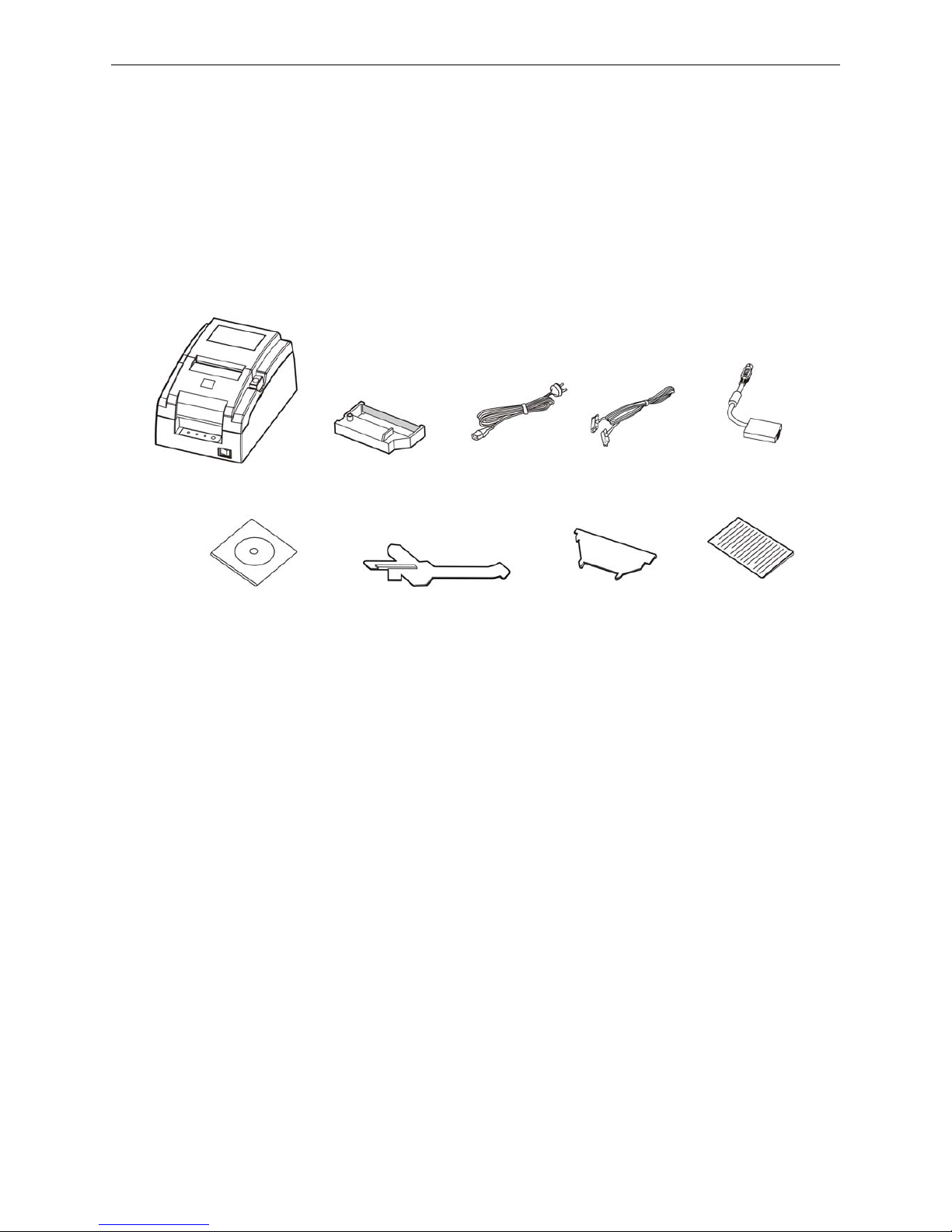
Check the following items in the package, if any of these items is missing, please contact your dealer:
(1) Printer; (2) Power cord; (3) Interface cable; (4) AC adapter; (5) Driver CD;
(6) Ribbon cartridge
compatible star RC 200B; (7) 57.5mm Paper stopper_mechanism; (8) 57.5mm Paper stopper_holder;
(9) Facility user's guide.
★ Interface cable is an optional part, you could select or cancel it base on your requirement.
2.2 Removing the Protective Materials
① Open the packing box, take out the printer.
② Save all the original packing materials, so that they can be used when transporting the printer.
2.3 Connecting Computer or Other Equipments
This printer is equipped with one data interface (parallel interface, serial interface, USB interface, USB
interface + Ethernet interface, Bluetooth or USB interface + Wi-Fi) and one cash drawer interface.
(According to specific interface standards) Connect the computer with correct cables.
Caution: Before connecting or disconnecting the cash drawer interface, parallel interface or
serial interface, you should make sure that the power of the printer is turned off. Only
after tightening the cable could turn on the printer, or else, it may damage the printer.
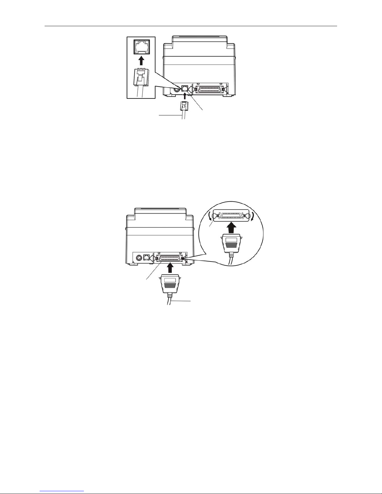
2.3.1 Connecting the Cash Drawer Cable
Make sure the printer is turned off. Plug one end of the cable into the cash drawer interface of the
printer and the other end connect to cash drawer. (Shown as figure 2-2)
Figure 2-1 Packing list
Printer
Facility User's
Guide
AC Adapter
Power Cord
57.5mm Paper
stopper_holder
Interface Cable
Driver CD
(Including User's Manual
and Driver)
Ribbon Cartridge
(Compatible Star
RC 200B)
57.5mm Paper
stopper_mechanism
Page 9
BP-007 User’s Manual
- 4 -
Note: You must use the proper cash drawer. Manufacturer will not honor warranty when using
improper cash drawer.
2.3.2 Connecting the Parallel Cable
1. Make sure that the computer and the printer are both turned off, connect the parallel cable to the
interface of the printer, and fasten the wire clips as shown in Figure 2-3.
2. Connect the other end of the cable to the computer’s parallel interface, and tighten the screws on
both sides.
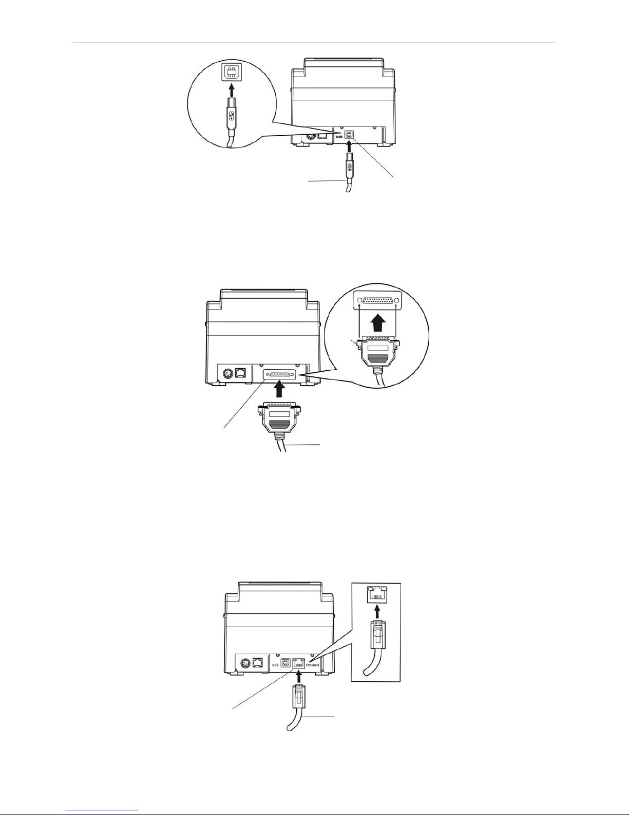
2.3.3 Connecting the USB Cable
1. Plug the USB cable A end (flat shape) into the computer's USB interface.
2. Plug the USB cable B end (square shape) into the printer's USB interface. (As shown in figure
2-4)
Caution: Don't impact the plug after connecting to the USB cable.
Fi
g
ure 2-3 Connecting the parallel cable
Figure 2-2 Connecting the cash drawer cable
Cash Drawer Interface
Cash Drawer Cable
Wire clips
Parallel Interface
Parallel Cable
Page 10
BP-007 User’s Manual
- 5 -
2.3.4 Connecting the Serial Cable
1. Make sure that the computer and the printer are both turned off, connect the serial cable to the
interface of the printer and tighten the screws as shown in Figure 2-5.
2. Connect the other end of the cable to the computer’s serial interface and tighten the screws on both
sides.
2.3.5 Connecting the Ethernet Cable
Plug the crystal end of the Ethernet cable (RJ-45) into the printer’s Ethernet interface, and then, plug
the other end into the LAN’s entrance. (Shown as figure 2-6)
Figure 2-5 Connecting the serial cable
Serial Cable
Serial Interface
Screw
Figure 2-4 Connecting the USB cable
Figure 2-6 Connecting the Ethernet Cable
Ethernet cable
Ethernet interface
USB Cable
USB Interface
Page 11
BP-007 User’s Manual
- 6 -
Note: The detailed information of the network settings, please refer to the User’s Manual.
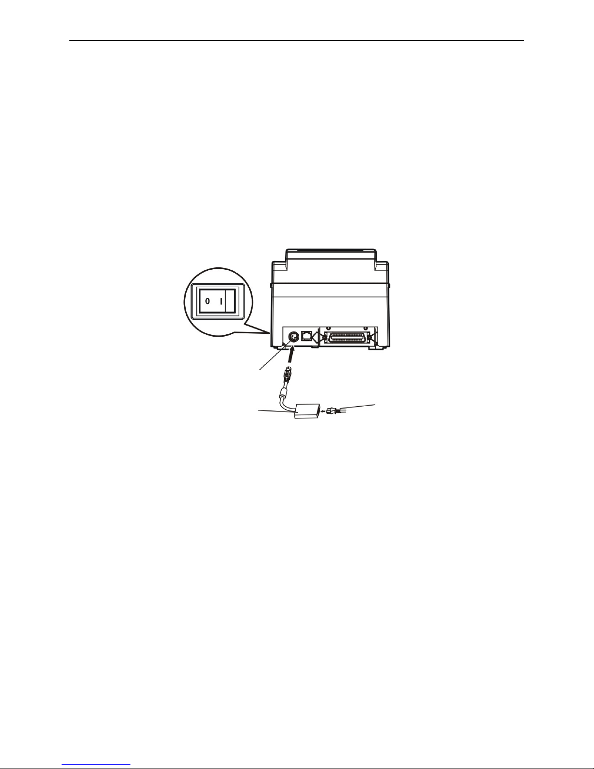
2.4 Connecting the Power Cord
1. Make sure the printer is turned off. (O mark on the power switch is pressed down).
2. Make sure the voltage of the electrical outlet matches that of the AC adapter.
3. Plug the AC adapter to printer's power supply inlet.
4. Plug one end of the power cord into the AC adapter, and then plug the other end of the power cord
into the grounded electrical outlet.
Warning: 1. If the voltage cannot match, please contact your dealer for assistance, and do not
plug in the power cord.
2. Please use the electrical outlet connecting the ground properly.
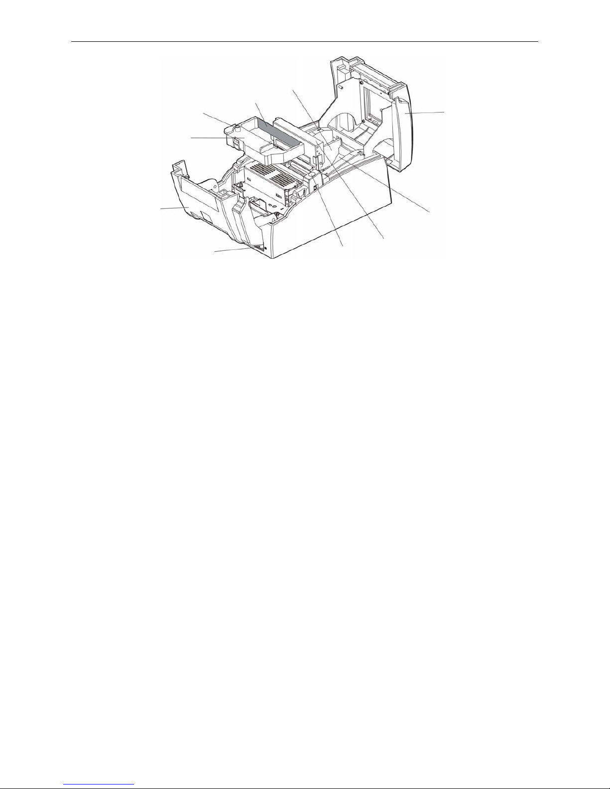
2.5 Installing the Ribbon Cartridge
1. Make sure the printer is turned off.
2. Please open the upper cover and front cover firstly, then turn up the auto-cutter assembly backwards,
and then, install the ribbon cartridge.
3. Turn the ribbon knob several times in the direction shown by the arrow to take up any slack in the
ribbon.
4. Insert the ribbon cartridge with the ribbon knob in the left and push the ribbon cartridge down until the
ribbon core is locked in place.
5. Turn the ribbon knob in the direction shown by the arrow again.
6. Turn the auto-cutter assembly down to the original position, and then close the upper cover and front
cover.
Figure 2-7 Connecting the power cord
Power Supply Inlet
AC Adapter
Power Cord
Page 12
BP-007 User’s Manual
- 7 -
Note: 1. When your print becomes faint, you need to replace the ribbon cartridge. Otherwise,
the print quality will be affected and the print head may be damaged.
2. To remove the old ribbon cartridge, first make sure the power is turned off, then as
the upper figure shown, hold the ribbon cartridge handle on the left side to take out
the ribbon cartridge. Install a new one as the above steps.
3. Please use the original
compatible star RC 200B ribbon cartridge only. Manufacturer
will not honor warranty when using unauthorized ribbon cartridge.
2.6 Installing the Driver
Please use the cable to connect computer with printer, then turn on the computer and the printer, put
the driver CD into the CD-ROM. Install driver by the following ways:
Auto-installing way
Double click the file “Setup.exe” in the driver disc, install driver by the following direct.
Note: Auto-installing way needs the operating system of Windows 2000 or above.
Hand operated installing way
Note: The hand-operated installing ways of serial interface and parallel interface are the same.
1) The installing steps of parallel interface for Windows 2000/XP/Vista are as follows:
1 Click “Start” → “Settings” → “Select Printers”.
2. Click “Add Printer”, then it pops up a window of “Add Printer Wizard”, click “Next”, then please read
the select guide carefully, such as, select “Local printer” in the “Local or Network Printer” window,
then click “next”.
3. A window of “Select a Printer Port” pops up, select a usable port. Such as, select “LPT1:
(Recommended Printer Port)”, click “Next”.
4. A window of “Install Printer Software" pops up, click “Have Disk...”, click “Next”.
5. A window of “Install From Disk” pops up. Please according to the operating system environment, you
Figure 2-8 Installing the ribbon cartridge
Ribbon Cartridge
(Compatible Star
RC 200B)
Ribbon Knob
Upper Cover
Front Cover
Power Switch
Cover-open Button
Auto-cutter Assembly
Ribbon Core
57.5mm Paper stopper_Holder
Paper Holder
Page 13

BP-007 User’s Manual
- 8 -
should select the path as follow: CD-ROM → “Driver” → “WIN2000 (XP-Vista-Win7)”, click “Open”,
then click “OK” to return to the window of “Install Printer Software”, select the respective model, click
“Next”.
6. Follow the guide click “Next” gradually till the installation is finished.
2) The installing steps of parallel interface for Windows 7 are as follows:
1. Click “Start” → “Device and Printers”.
2. Click “Add Printer”, then it pops up a window of “Add Printer Wizard”, click “Next”, then please read
the select guide carefully, such as, select “Local printer” in the “Local or Network Printer” window,
then click “next”.
3. A window of “Select a Printer Port” pops up, select a usable port. Such as, select “LPT1:
(Recommended Printer Port)”, click “Next”.
4. A window of “Install Printer Software” pops up, click “Have Disk...”, click “Next”.
5. A window of “Install From Disk” pops up. Please according to the operating system environment,
such as Windows XP operating system, you should select the path as follow: CD-ROM → “Driver”
→“WIN2000 (XP-Vista-Win7)”, click “Open”, then click “OK” to return to the window of “Install
Printer Software”, select the respective model, click “Next”.
6. Follow the guide click “Next” gradually till the installation is finished.
The USB interface installing steps for Windows 2000/XP/Vista/Win7 are as follows:
The following steps are used Windows XP as example. There are slight differences among different
operating systems.
1. Connect the printer to computer with an USB cable and turn on the printer.
2. After the computer find out new hardware and finish searching, pop up a window of “Found New
Hardware Wizard”, choose “Install from a list or specific location (Advanced)”, click “Next”.
3. A window of “Found New Hardware Wizard” — “Please choose your search and installation
options” pops up, choose “Don't search, I will choose the driver to install”, click “Next”.
4. A window of “Add Printer Wizard” pops up, click “Have Disk...”, click “Browse”.
5. A window of “Install From Disk” pops up. Please according to the operating system environment,
you should select the path as follow: CD-ROM → “Driver” → “WIN2000 (XP-Vista-Win7)”, click
“Open”, then click “OK” to return to the window of “Add Printer Wizard", select the respective model,
click “Next”.
6. Follow the guide click “Next” gradually till the installation is finished.
The installing steps for Windows 98 are as follows:
(1) The installing steps with a parallel cable or a serial cable:
1. Click “Start” → “Settings” → “Printers”.
2. Click “Add Printer”, then a window of “Add Printer Wizard” pops up, click “Next”, then please read
the select guide carefully, such as, select “Local printer” in the “Local or Network Printer” window,
then click “Next”.
3. A window of “Click the manufacturer and model of your printer” pops up, click “Have Disk...”, please
click “Browse”, select the path as follow: CD-ROM →
“Driver” → “WIN98 (WINME)”, then
click “OK”.
4. A window of “Install From Disk” pops up, click "OK, return to a window of “Add Printer”, select the
respective model, and then click "Next".
Page 14

BP-007 User’s Manual
- 9 -
5. A window of “Printer port” pops up, select “Available ports”, such as, select “LPT1: Printer Port”,
click “Next”, and then show the printer’s name. If the system is not installed by other printer driver
process, the printer is treated as default printer by the application process of Window98
environment, click “Next”. Otherwise according to prompt, choose the printer is default: “Yes”, click
“Next”, choose “Yes-(recommended)”, click “Finish”. A window of “Printer test page completed”
pops up, click “Yes”.
6. The printer driver process is installed successfully.
(2) The installing steps with an USB cable:
Note: 1. As the system of Windows 98/ME doesn’t have integrated USB driver control, please
install USB driver before using USB interface printing. Then install USB printer driver.
2. If it has installed the USB driver, please install the USB printer driver directly as the
following steps.
USB driver installing steps:
1. Connect an USB cable and turn on the printer.
2. After the computer find out new hardware and finish searching, a window of “Add New Hardware
Wizard” pops up, click “Next”.
3. A window of “Add New Hardware Wizard” — “Windows operation” pops up, choose “Search the
best driver for the device (recommended)”, and click “Next”.
4. A window of “Search for new drivers” pops up, check “Specify a location”, click “Browse”, select
the path as follows: CD → ROM → “Driver”-“[WIN98 (WINME) \ USBdriver]”, then click “OK”.
5. Return to a window of “Search for new drivers”, click “Next”; a window of “Windows driver file
search for the device” pops up, click “Next”.
6. After the system finishing installing the file automatically, a window of “USB Print Supported”
pops up, click "Finish".
7. The printer USB driver process is installed successfully.
USB printer driver installing steps:
1. Click “Start” → “Settings” → “Printers”.
2. Click “Add Printer”, then a window of “Add Printer Wizard” pops up, click “Next”.
3. A window of “Click the manufacturer and model of your printer” pops up, click “Have Disk...”,
please click “Browse”, select the path as follow: CD-ROM → “Driver” → “WIN98 (WINME)”, and
then click “OK”.
4. A window of “Install From Disk” pops up, click “OK”, return to a window of “Add Printer”, then click
"Next".
5. A window of “Printer port” pops up, select “Available ports”, select “JMUSB”, click "Next", and
then show the printer’s name. If the system is not installed by other printer driver process, the
printer is treated as default printer by the application process of Window98 environment, click
“Next”. Otherwise according to prompt, choose the printer is default: "Yes", click "Next" choose
“Yes-(recommended)”, click “Finish”. A window of “Printer test page completed” pops up, click
“Yes”.
6. The printer driver process is installed successfully.
Page 15
BP-007 User’s Manual
- 10 -
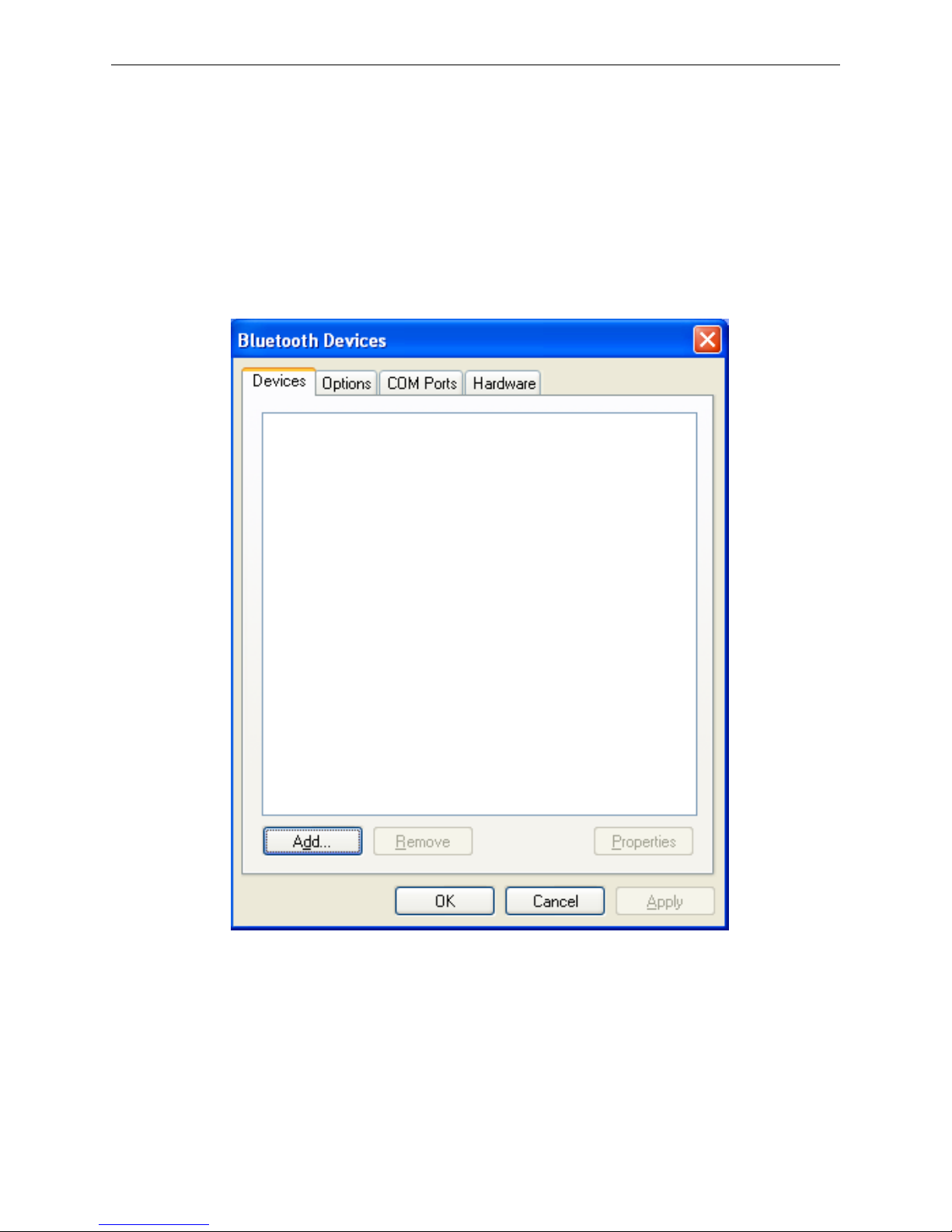
2.7 Installing Bluetooth Interface Driver
Note: Select to install this driver according to the chosen model.
1. Adjust the printer serial to 38400bps, 8 data bits, no check bit, 1 stop bit and the protocol is
DTR/DSR.
2. Choose the appropriate Bluetooth adapter, the operation system is Window XP or above which with
Bluetooth adapter driver.
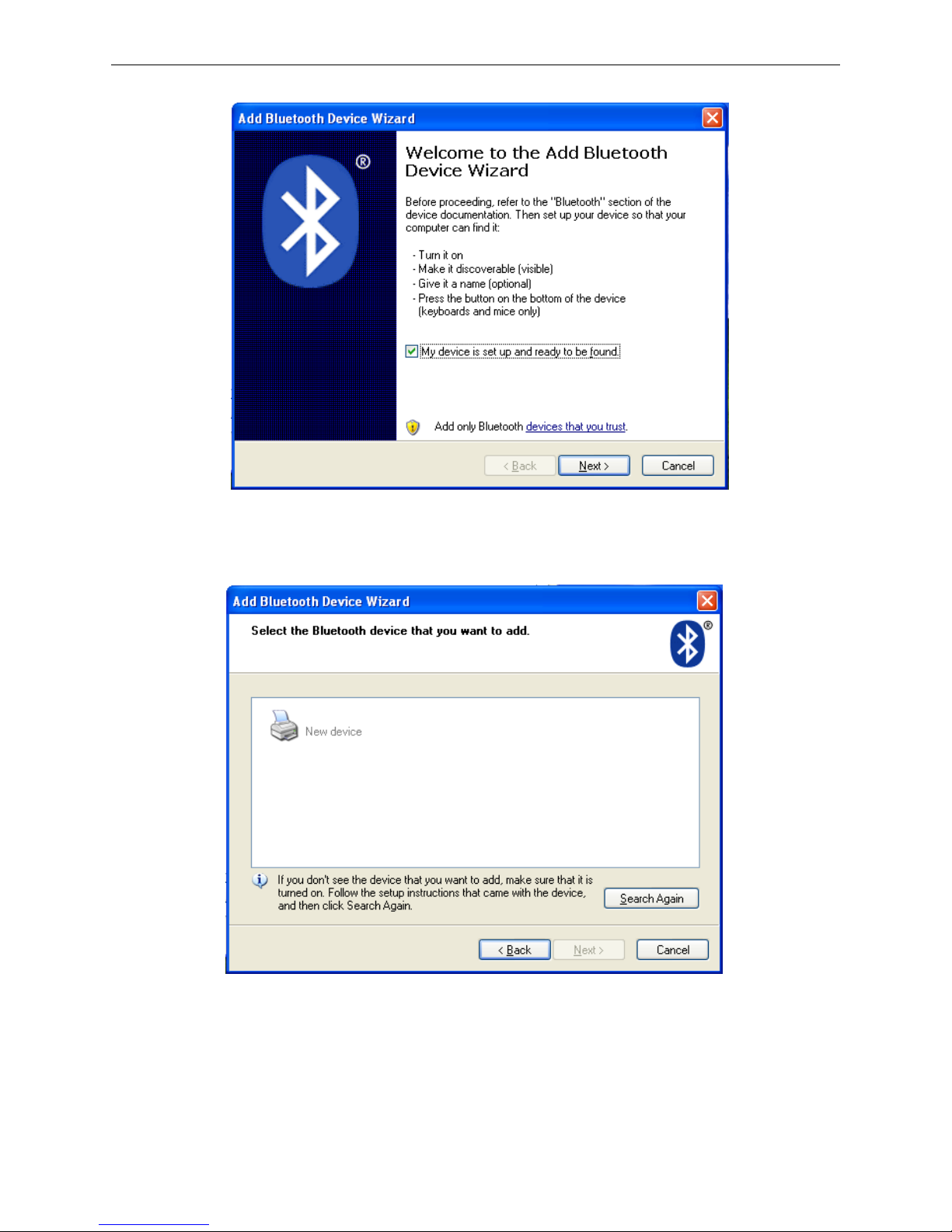
3. Turn on the printer, search Bluetooth device in Window XP system, and click “Add”.
4. Tick off the option of “My device is set up and ready to be found.” Click “Next” to continue.
Page 16
BP-007 User’s Manual
- 11 -
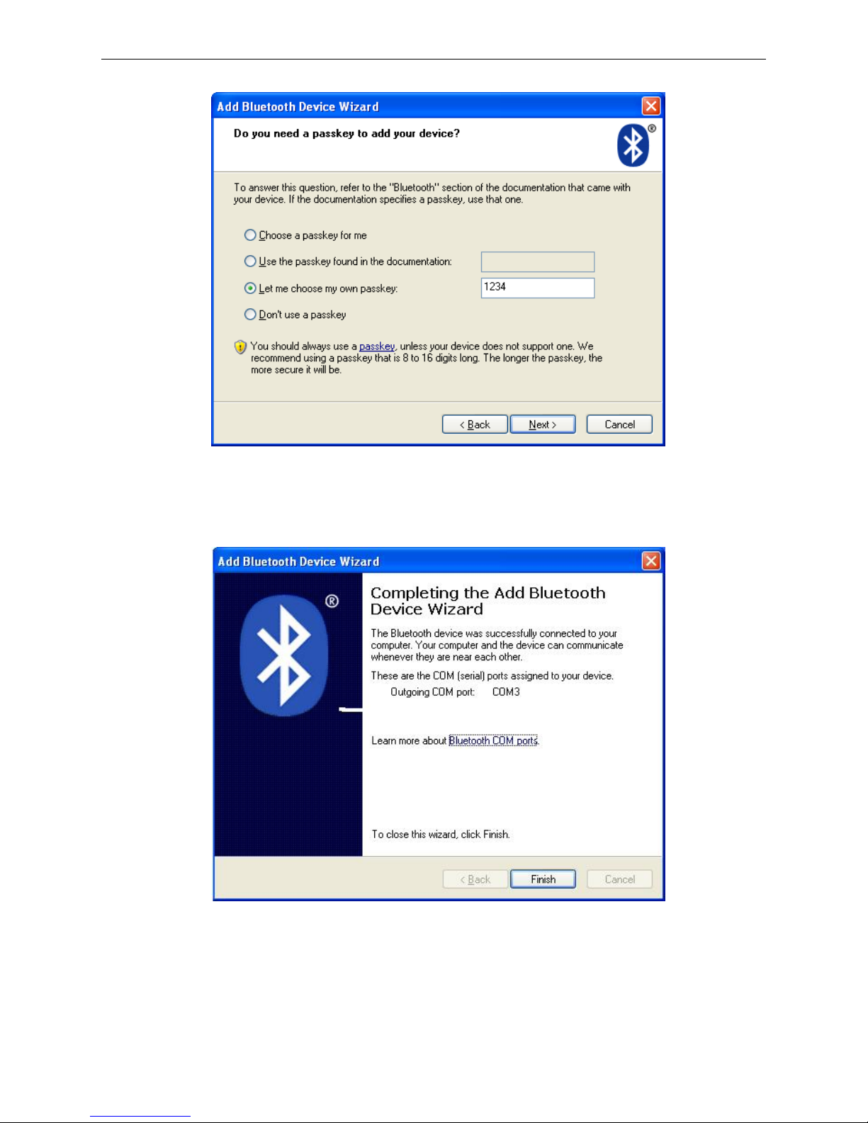
5. Select the “BP-007”, and then click “Next”.
6. Tick off the option of “Let me choose my own passkey” and enter “1234” as shown, then click “Next”.
BP-007
Page 17
BP-007 User’s Manual
- 12 -
7. Record the Outgoing COM port and click “Finish”, then reboot the computer.
8. Set the printer driver print port as the outgoing port and the installation is finish.
Note: Every Bluetooth device has its own address. Please reinstall it when replacing the
Bluetooth device.
Page 18
BP-007 User’s Manual
- 13 -
2.8 Network Settings
Please use Birch network setting software NetFinder to set the IP address for Birch Ethernet interface
network printers, which can be found in the CD or downloaded from www.birch.com.tw
.
Caution: The network printing function needs the operation system of Windows2000 or above.
2.8.1 Connecting Printer
Power on the printer, connect with the Ethernet cable which has been connected to LAN, and look into
the information of Ethernet LED indicator to ensure the printer has entered into the normal connection.
2.8.2 Setting IP Address
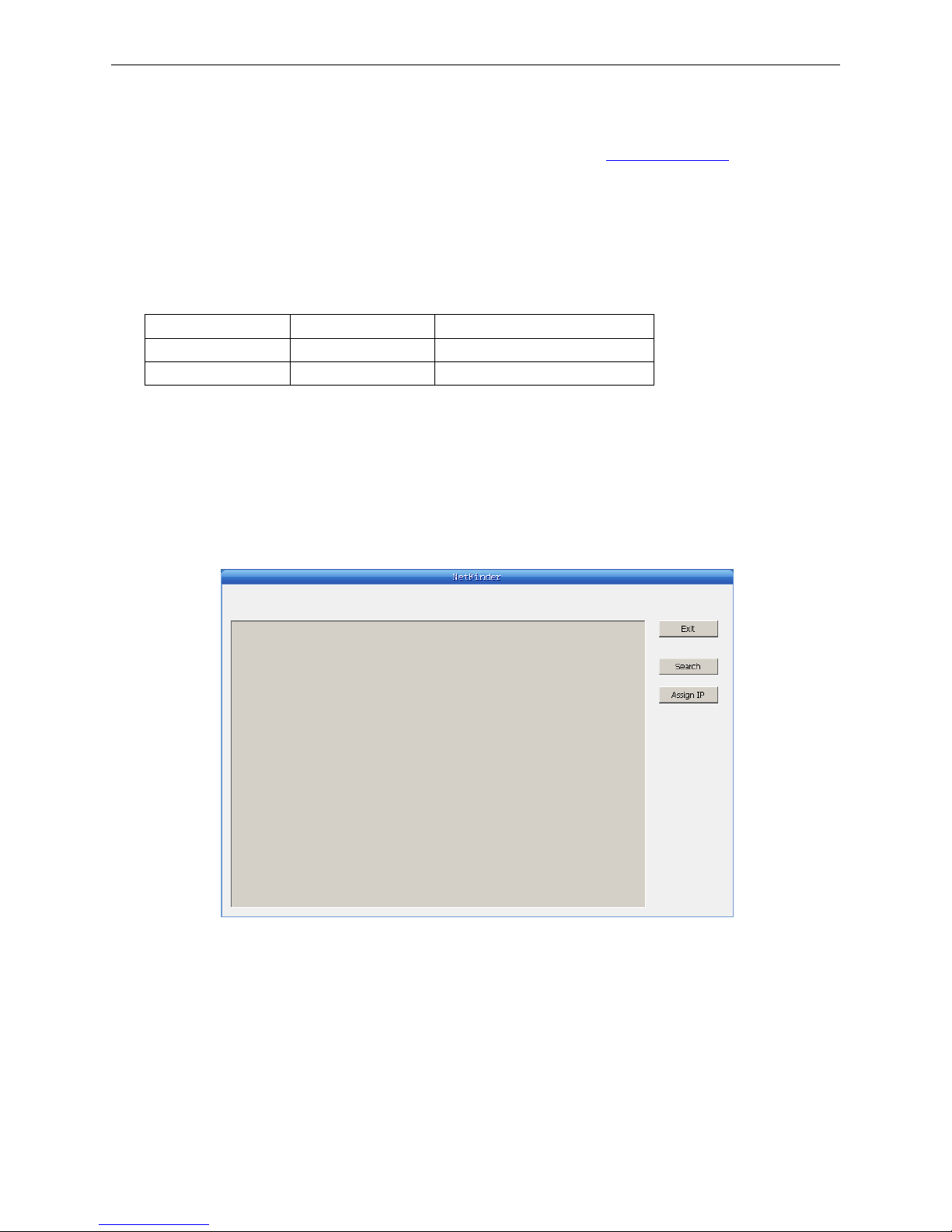
1. Run NetFinder Software
Double click NetFinder.exe in the PC which connects the printer in the same LAN. The figure of the
software is shown as follows:
Button description:
Exit — Exit from the software
Search — Search printers in the same LAN
Assign IP — Modify the IP address and other settings for the specified printer.
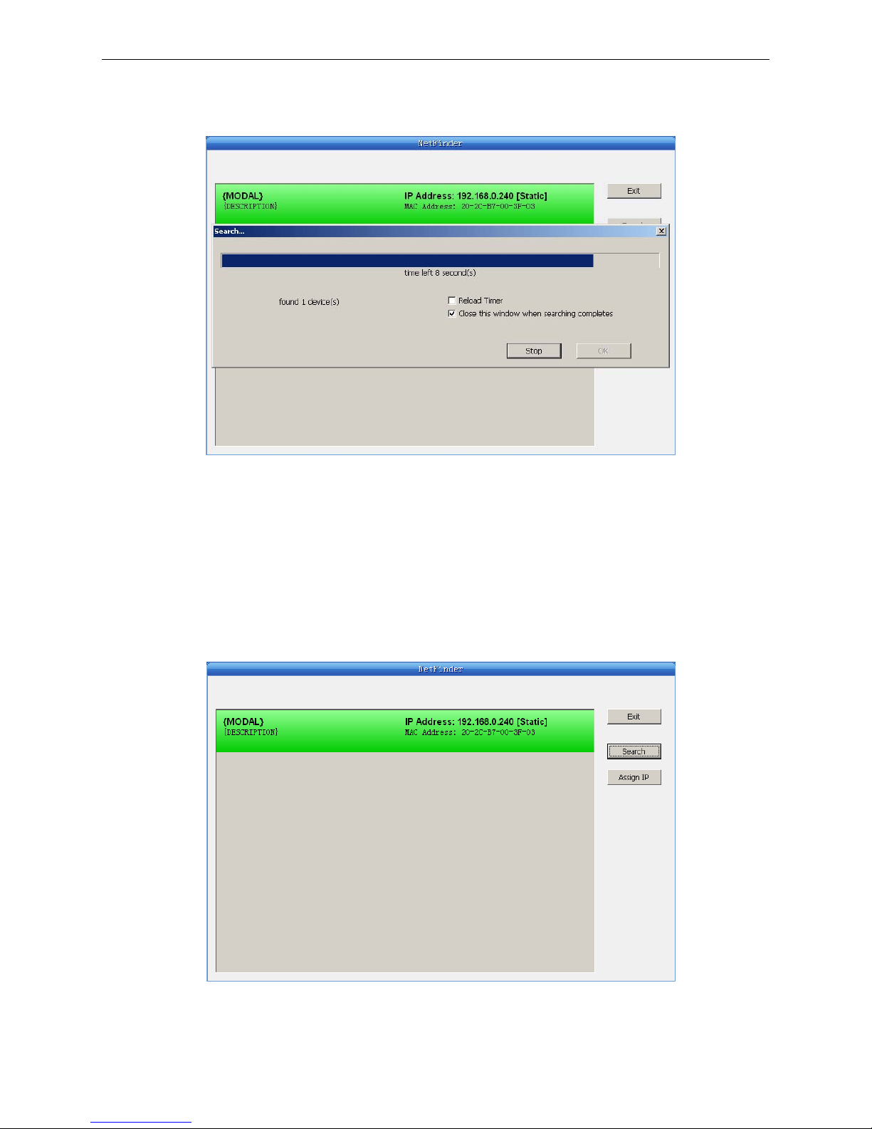
2. Search printer
Click “Search” button in the main interface, the dialog box appearing will begin searching
automatically and show appearance, listing a printer in the main interface if found. The time is
Yello w LED Green LED Description
ON Blink Connecting to network
OFF OFF Not connecting to network
Page 19
BP-007 User’s Manual
- 14 -
counting down in the progress bar (10s in total) and the search will finish as soon as the time is over.
When going on searching, press “search” button again.
If the printer still can not be found out when the network connection is correct in the same network,
Please check whether the network fire wall on the PC open or not. If there is fire wall, please close it
temporarily, open again after finishing searching and setting a printer completely.
3. Setting printer’s IP address
The printer’s information is listed in the main interface, the left side of which is the model and
description and the right is the IP and MAC address. What’s more, the assign mode (dynamic/static)
is noted behind the IP address.
1) Correlative description for IP address settings
In order to search and set printer’s IP address conveniently for the first time, the factory default
Page 20

BP-007 User’s Manual
- 15 -
setting is DHCP mode which assigns IP address dynamically. If there is no DHCP server in the
connected LAN and printer is set to DHCP mode as well, then it will use the internal pre-set address
(IP: 10.0.0.1, Subnet Mask: 255.255.255.0) automatically.
It is suggested that printer’s IP set to static in actual usage, which can cut down the time when
initializing the Ethernet interface as the printer is turned on and prevent IP conflicts (The dynamic
address used in printer may conflict with another one). The network segment part of the IP address
and Subnet Mask must be the same as those of PC connecting with a printer. For example, the
address of working PC is 192.168.0.1/255.255.255.0 (IP/Subnet Mask), then which of printer
should be set to 192.168.0.x/255.255.255.0(x=2~254 and should avoid the IP in used. It is not
restricted for NetFinder to search printers in the same network but different segment parts (can not
stride gateway). Relative glossary of IP address may refer to corresponding information.
2) Setting printer’s IP address
Select the printer information to be modified (black frame appears), click “Assign IP” button. Set the
IP in the dialog box appearing.
Check the “Use DHCP” if need to assign dynamic address, the settings above will be disabled
automatically. Please make sure there is a DHCP server in the network, or the printer can not
receive an effective IP address.
When to specify static address, uncheck “Use DHCP” and fill in “IP address”, “Subnet Mask” and
“Default Gateway”. If there is no gateway in the network, fill 255.255.255.255 in the “Default
gateway”. “IP address” and “Subnet Mask” should obey the assigning rules of local LAN (Ethernet),
please enquire the administrator of networks which the printer connects to for more details.
Click “OK” to send address setting information to the specified printer. The printer takes response
after “Close this window on success” is checked, and then this dialog is closed automatically. Select
“Reload Timer” then the software will wait for the printer’s response. Generally, printer will take
response in a circle time if network connection is correct.
Click “Cancel” if you abandon the modification.
Click “Search” in the main interface again to update printer information after modifying the printer’s
IP address.
3) Report printer’s IP address
Report the printer’s IP address, which will be used in the section “Newly-install printer network driver”
or “Upgrade-install printer network driver (setting driver’s network port)”.
2.9 Wi-Fi Setting
Please use Birch network setting software WiFiConfig to set the IP address for Birch Wi-Fi interface
network printers, which can be found in the CD or downloaded from www.birch.com.tw
.
Caution: The network printing function needs the operation system of Windows2000 or above.
Caution: Wi-Fi interface transfers data through wireless network. The wireless signal may be
affected by the surrounding environment, please ensure the signal around printer
location is well enough.
Page 21
BP-007 User’s Manual
- 16 -
2.9.1 Connect to the Printer, Run the WiFiConfig Software
Connect the printer and the computer with the USB interface cable, make sure the printer is in normal
working condition, and then turn on both the printer and the computer, double click WiFiConfig.exe in
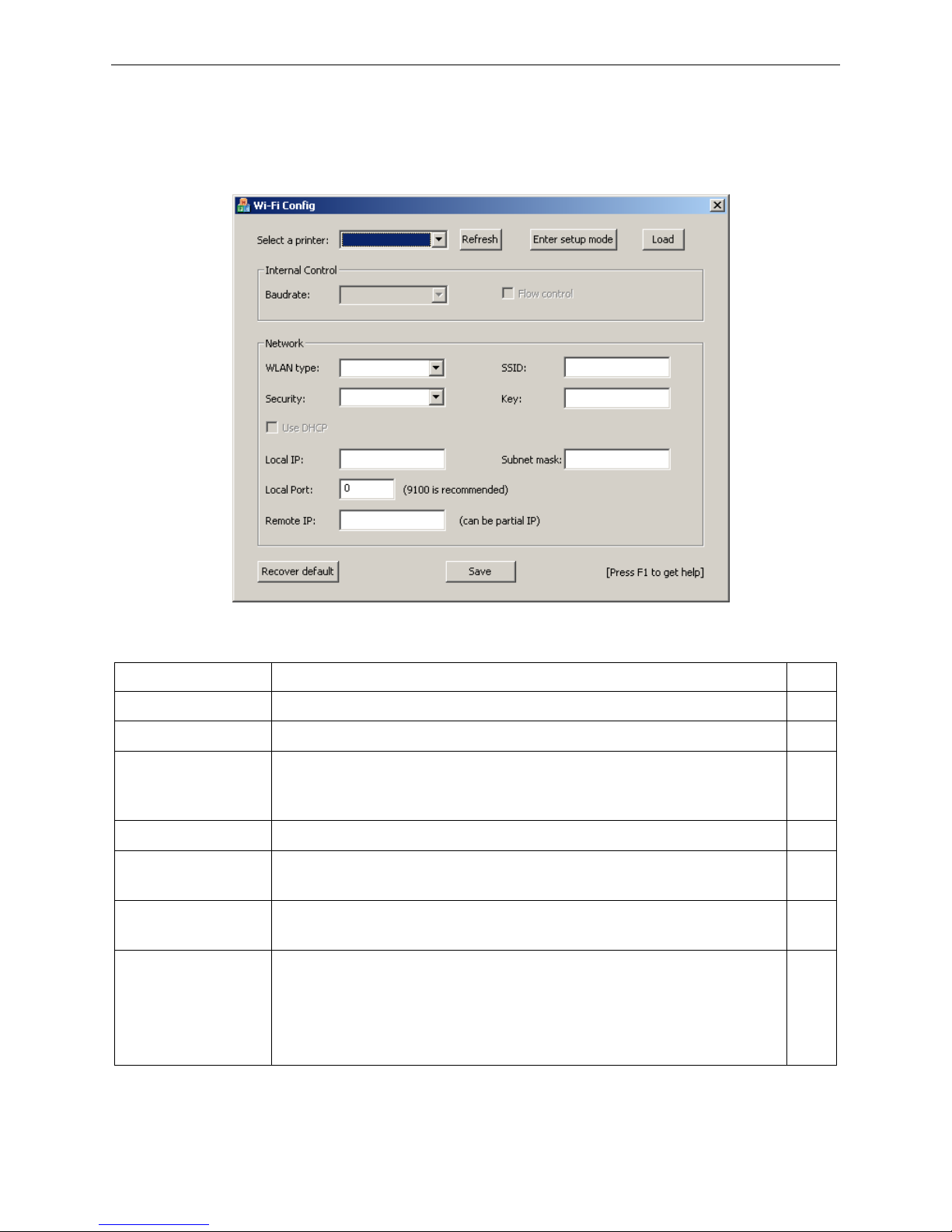
the driver CD. The software interface is as follows:
Explanation Table
Item Explanation Note
Select a printer Select the printer model in the list.
Refresh Refresh the printer model.
Enter setup mode
Enter setup mode.
Note: If the printer has entered setup mode, please don’t click “Enter
setup mode” again.
Load Load the current Wi-Fi parameter.
Baudrate
Set the serial baudrate. This parameter setting usually does not need to
change.
Flow control
Control the flow of communication data. There is no need to change this
parameter normally.
WLAN type
Select the WLAN type as Infrastructure, Ad Hoc or OFF.
Infrastructure: Select infra, through router to connect network;
Ad Hoc: Select ad-hoc, wireless network card can communicate with
printer directly;
OFF: Select the printer Wi-Fi interface off.
Page 22

BP-007 User’s Manual
- 17 -
SSID
Network name.
The longest network name is 32 characters and there is no space
between characters.
When WLAN type is Infrastructure, the network name is the same with the
router’s network name;
When WLAN type is Ad Hoc, the network name is the same with the
wireless network card’s network name.
Security Select the security mode.
Key
Enter the corresponding key.
When “Security” is selected to “None”, do not need to enter key.
Use DHCP
Select to use dynamic IP assignment or not. There is no need to change
this parameter normally.
Note: Dynamic IP assignment is uncertain, it is easy lead to
unsuccessful communication because of IP mismatching, so
we don’t suggest using dynamic assignment.
Local IP
IP address of printer Wi-Fi interface.
Note: This IP address should not conflict with other network
devices.
If “Use DHCP” has been selected, then this IP is invalid.
Subnet mask The subnet mask of printer Wi-Fi interface.
Local port The local port of printer Wi-Fi interface. It is suggested using 9100.
Remote IP
The remote IP is a segment of the LAN or the PC IP which communicates
with printer.
When filling in IP, such as “192.168.0.1”, PC is communicate with printer
respectively; When filling in segment, such as “192.168.0”, the PCs in this
segment all can communicate with the printer.
Recover default
Recover the default setting.
After recover the default setting, you should set the Wi-Fi parameters
again.
Save Save the setting parameter. After saving, please reboot the printer.
Press F1 to get help Press F1 to get the help information.
2.9.2 Set Wi-Fi Parameters
Note: 1. You should use the USB interface cable to connect the printer and computer before
configuring Wi-Fi parameters, and run the WiFiConfig software.
2. Configuring Wi-Fi parameters should in the setup mode (besides recover the default
setting).
3. You should make sure the printer is in normal working condition before running the
WiFiConfig software.
The detail parameter configuration instruction and cautions please refer to the Help of WiFiConfig.exe.
Press F1 to pop up the Help instruction when running that software.
1. Connect the printer and the computer with a USB interface cable, and then turn on both the printer
and the computer, run the WiFiConfig software.
Page 23

BP-007 User’s Manual
- 18 -
2. Check if the corresponding printer model is in the list of Select a printer, if no, please click “Refresh”,
select the corresponding printer model after it appears.
3. Click “Enter setup mode”, it will pop up a Success dialog box when it enters the mode successfully.
After entering setup mode, printer could not receive print data, and you should restart the printer
before printing.
4. Click “Load”, the printer would load the current Wi-Fi setting.
5. Sets the network communication parameters.
Please set the corresponding network communication parameters according to the actual network
circumstances. The detailed information please enquire the network administer.
WLAN type: Select the network mode. Through hotspot, connect the network with router mode,
select “Infrastructure”; Wireless network card communicates with the printer directly,
select “Ad Hoc”; Do not need the Wi-Fi printing function, select “OFF”.
SSID: SSID is the corresponding network name. When “WLAN type” is selected to “Infrastructure”,
network name and the router network name should be the same; when “WLAN type” is
selected to “Ad Hoc”, network name and the wireless network card name should be the same.
Security: Select the security mode of the selected network.
Key: Enter the key of the selected network. When “Security” is selected to “None”, you do not need
to enter key.
6. Set the printer IP parameters.
Please set the corresponding printer IP parameters according to the actual network circumstances.
The detail information please enquire the network administer.
Note: Dynamic assign IP is uncertain, it is easy lead to unsuccessful communication because
of IP mismatching, so we don’t suggest using dynamic assignment.
IP address and subnet mask should obey the assignment rule of the local LAN.
Use DHCP: Select to use dynamic IP assignment or not. When select “Use DHCP”, the IP parameters
would be invalid. Please ensure there it DHCP server in the network firstly, or else the
printer would not achieve the valid IP address. Do not select “Use DHCP”, you should
specify static address.
Local IP: The IP address of printer Wi-Fi interface.
Subnet mask: The subnet mask of printer Wi-Fi interface.
Local port: The local port of the printer Wi-Fi interface. It is suggested using 9100.
Record the printer IP address and port number, the IP address and port number would use in the
Newly-install way or Upgrade-install way in next chapter.
7. Setting remote IP parameters.
The remote IP is a segment of the LAN or the PC IP which communicates with printer.
When filling in IP, such as “192.168.0.1”, PC communicates with printer respectively; when filling in
segment, such as “192.168.0”, the PCs in this segment all can communicate with the printer.
8. After finish setting, click “Save” to save the setting and then restart the printer.
2.9.3 Checking Wi-Fi Parameters
After setting Wi-Fi network parameters, you should check the parameters to ensure the Wi-Fi network
Page 24
BP-007 User’s Manual
- 19 -
connection is properly.
1. Through “ping” command to check if the printer connects to network or not.
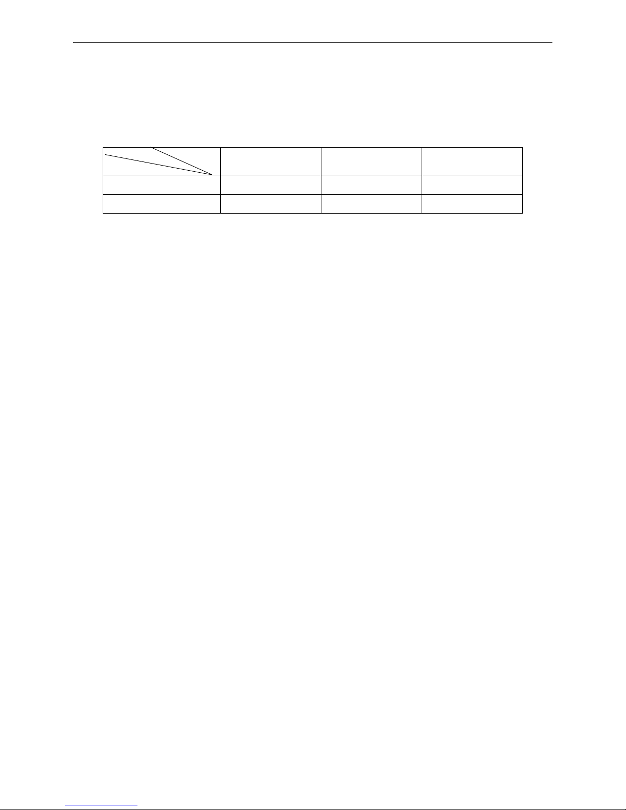
2. When “WLAN type” is select to “Infrastructure”, you could look into the Wi-Fi indicator lights to judge
the connection status.
Indicator Lights Description
2.9.4 Recover the Default Setting
When the malfunctions of the Wi-Fi parameters lead to the printer unable to connect with the network,
you could recover the default setting to set the parameters again.
Note: Printer does not need to enter setup mode when recovering the default setting. If the
printer has entered into setup mode, please restart the printer before recovering the
default setting.
1. Connect the printer and the computer with a USB interface cable, and then turn on both the printer
and the computer and run the WiFiConfig software.
2. Check if the corresponding printer model is in the list of Select a printer, if no, please click “Refresh”,
select the corresponding printer model after it appears.
3. Click “Recover default”, wait several seconds and a dialog box would pop up to denote the recovery
is successful or not.
4. After finishing recovering, please restart the printer and set the Wi-Fi parameters again.
2.10 Installing Printer Network Driver
The ways of installing network driver are divided into Newly-install way and Upgrade-install way
according to whether the PC installs the printer driver or not.
If the printer driver hasn’t been installed on the PC, adopt newly-install way whose steps are shown in
“Newly-install printer network driver”.
If the printer driver has been installed on the PC, adopt Upgrade-install way whose steps are shown in
“Upgrade-install printer network driver”.
1. Newly-install printer network driver
1) Click “Start” → “Settings” → “Select Printers”.
2) Click “Add printer”, then a window of “Add Printer Wizard” pops up, click “next”, then please read the
select direct carefully. Such as, select “local or Network Printer”, then click “next”.
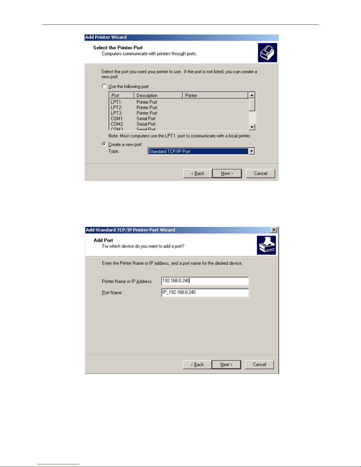
3) A window of “Select the Printer port” pops up, select a port you want your printer to use. For example,
select “Create a new port”, select “Standard TCP/IP Port” in the port, click “next”.
4) A window of “Add standard TCP/IP Printer Port Wizard” pops up, click “Next”.
Infrastructure Ad Hoc OFF
Connect ON ON BLINK
Disconnect BLINK ON BLINK
Network
Light
Communication
Page 25
BP-007 User’s Manual
- 20 -
5) A window of “Add Port” pops up, enter the IP address reported by the “Setting printer’s IP address”
in the “Printer Name or IP Address” column. Take IP address “192.168.0.240” for example. “Port
Name” is created automatically after finishing filling in IP address.
6) A window of “Additional Port Information Required” pops up, select “Custom” in the “Device Type”,
then click “Settings”.
Page 26
BP-007 User’s Manual
- 21 -
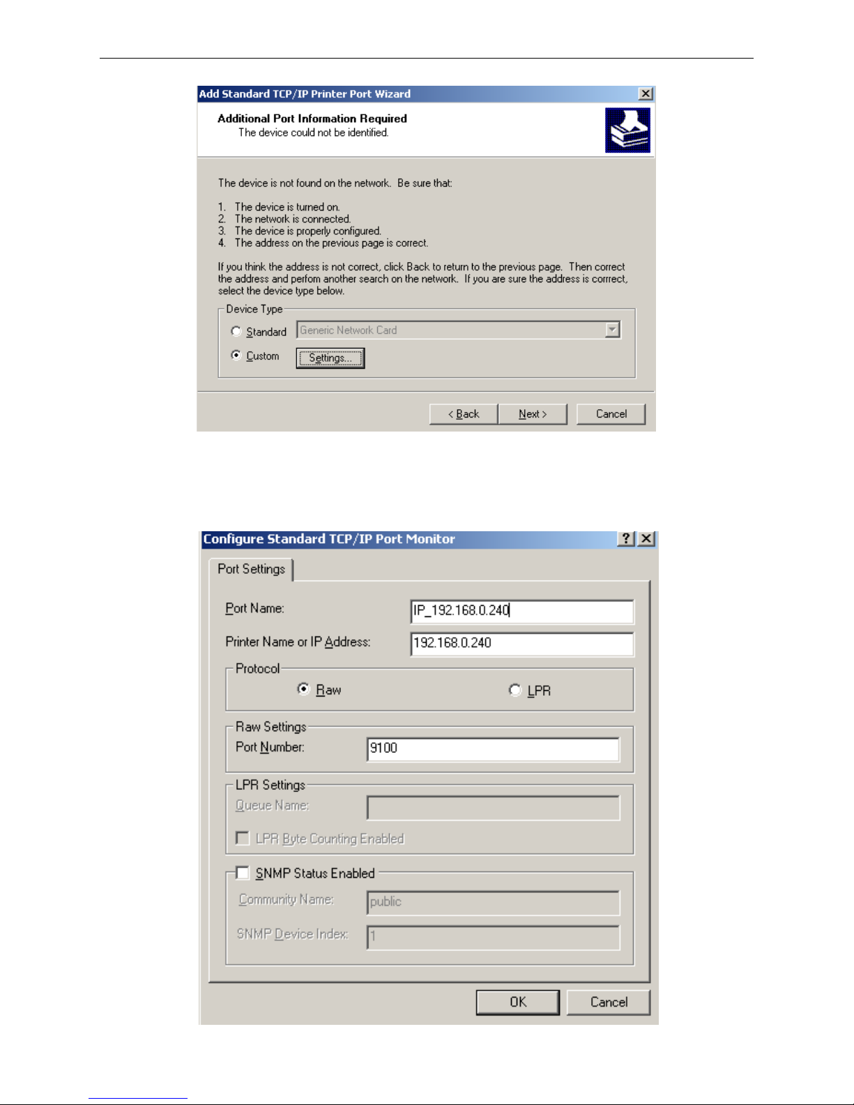
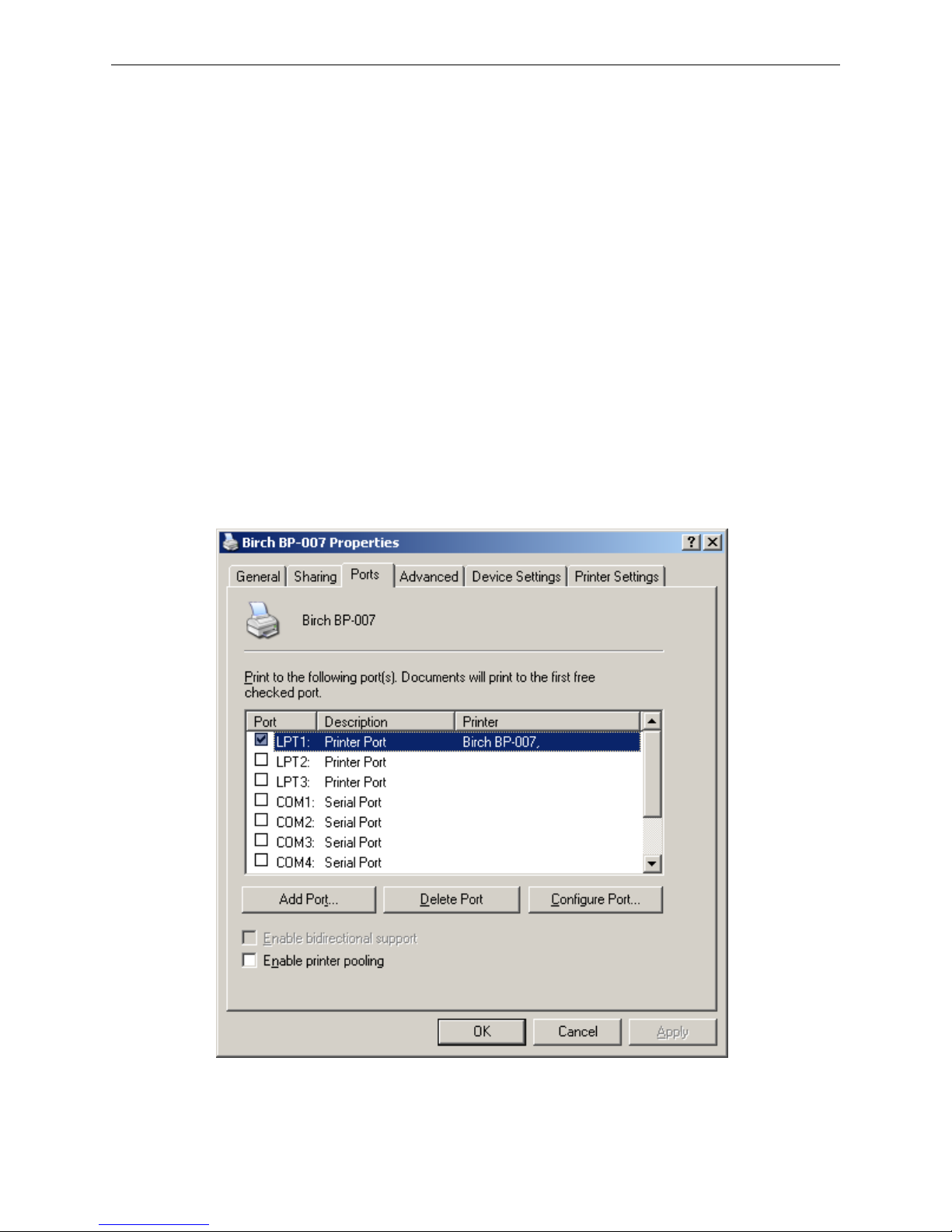
7) A window of “Port Settings” pops up. Affirm that “Port name” and “Printer name or IP address” are
correct, “Protocol” is “RAW” and “Port Number” is “9100”, click “OK”.
Page 27
BP-007 User’s Manual
- 22 -
8) Return to “Additional Port Information Required”, click “Next”.
9) A window of “Completing the Add Standard TCP/IP Printer Port Wizard” pops up, click “Finish”.
10) In the selection of "Manufacturers/Printers", click “Have Disk”, and then click “Next”.
11) A window of “Install From Disk” pops up. Please according to the operating system environment,
such as Windows 2000/XP/Vista/Win7 operating system you should select the path as follows:
CD-ROM-“Driver”-“WIN2000 (XP-Vista-Win7)”, click “Open”, then click “OK” to return to the
window of “Install Printer Software”, select the respective model, click “Next”.
12) Follow the direct click “next” gradually till the installation is finish. At this time, printer network driver
is installed completely.
2. Upgrade-install printer network driver (setting driver’s network port)
If PC has installed the printer’s driver, set driver’s network port to carry out network printing. The
concrete steps are shown below:
1) Click “Start” → “Settings”, select “Printers”.
2) Right click BP-007 driver, click “Properties” on the window coming out.
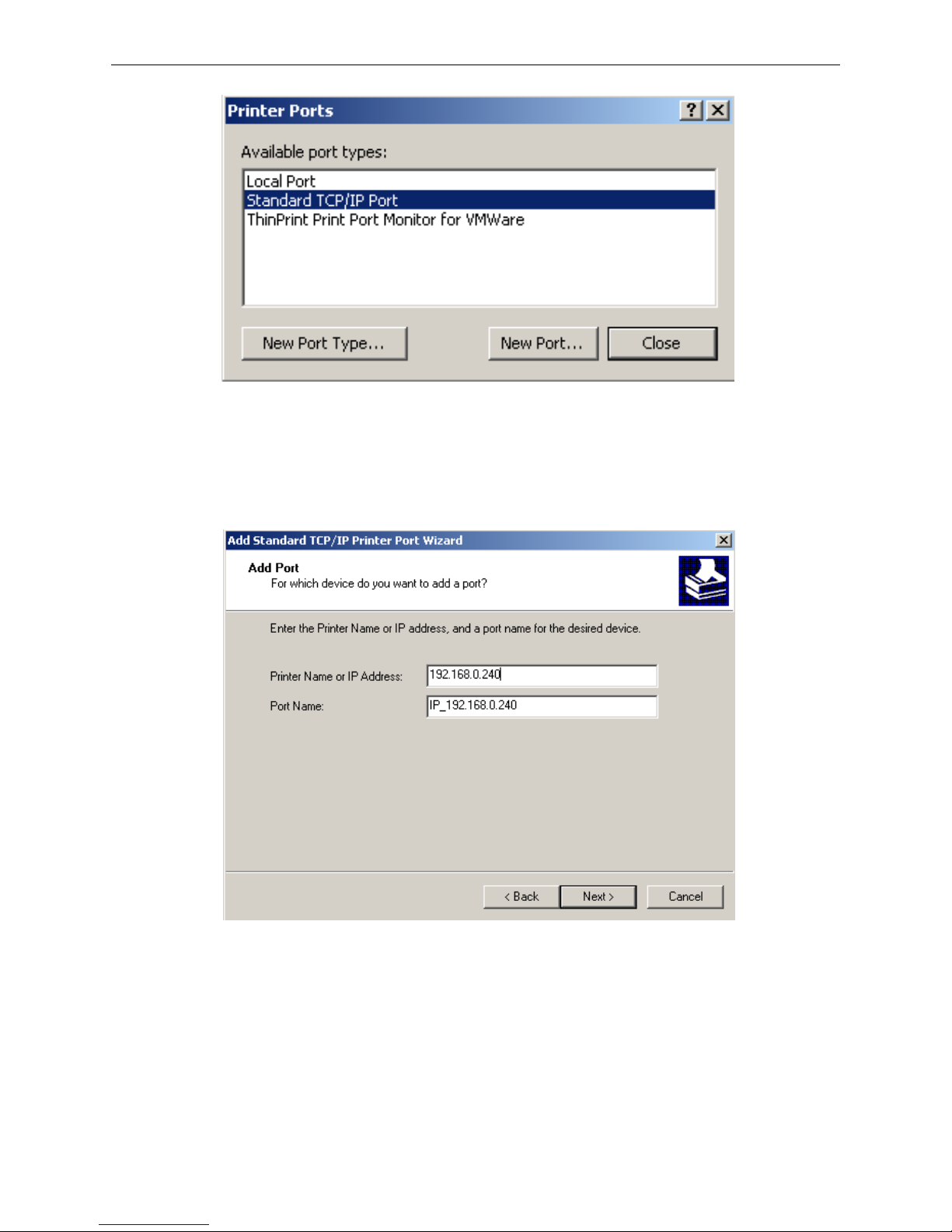
3) A window of “Properties” pops up, click “Ports” and “Add Ports”.
4) A window of “Printer port” pops up, select “Standard TCP/IP Port”, click “New port”.
Page 28
BP-007 User’s Manual
- 23 -
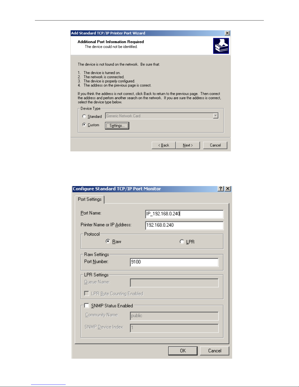
5) A window of “Add Standard TCP/IP Printer Port Wizard” pops up, click “Next”.
6) A window of “Add a port” pops up, import the IP address reported by the “Setting printer’s IP
address” in the “Printer name or IP address” column. Take IP address “192.168.0.240” for
example. “Port name” is created automatically after finishing filling in IP address. Click “Next”.
7) A window of “Additional Port Information Required” pops up, select “Custom” in the “Device Type”,
then click “settings”.
Page 29
BP-007 User’s Manual
- 24 -
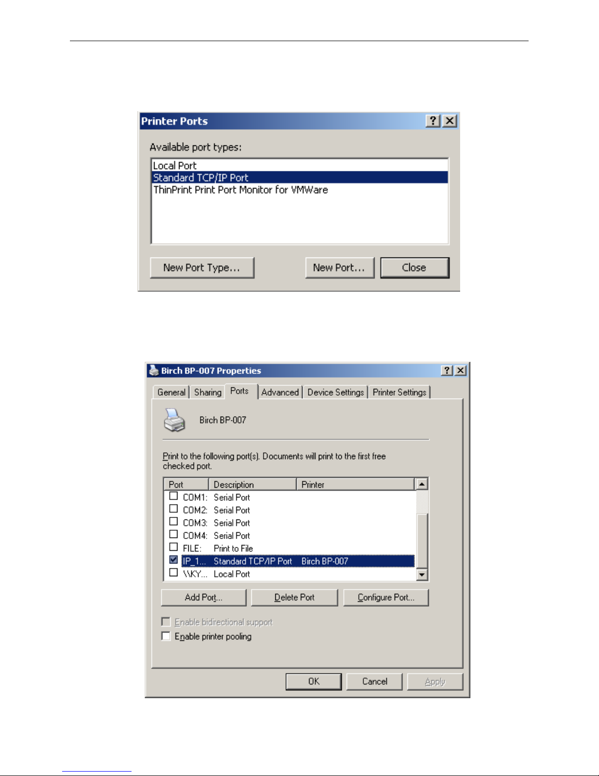
8) A window of “Port Settings” pops up. Affirm that “Port name” and “Printer name or IP address” are
correct, “Protocol” is “RAW” and “Port Number” is “9100”, click “OK”.
Page 30
BP-007 User’s Manual
- 25 -
9) Return to “Additional Port Information Required”, click “Next”.
10) A window of “Completing the Add Standard TCP/IP Printer Port Wizard” pops up, click “Finish”.
11) Return to “Printer Ports”, click “Close”.
12) Return to “Properties”, make sure the network port is selected, click “Apply”, and then click
“Close”. Thus, printer’s network port setting is finished.
Page 31
BP-007 User’s Manual
- 26 -
Chapter 3 Control Panel
3.1 Control Panel
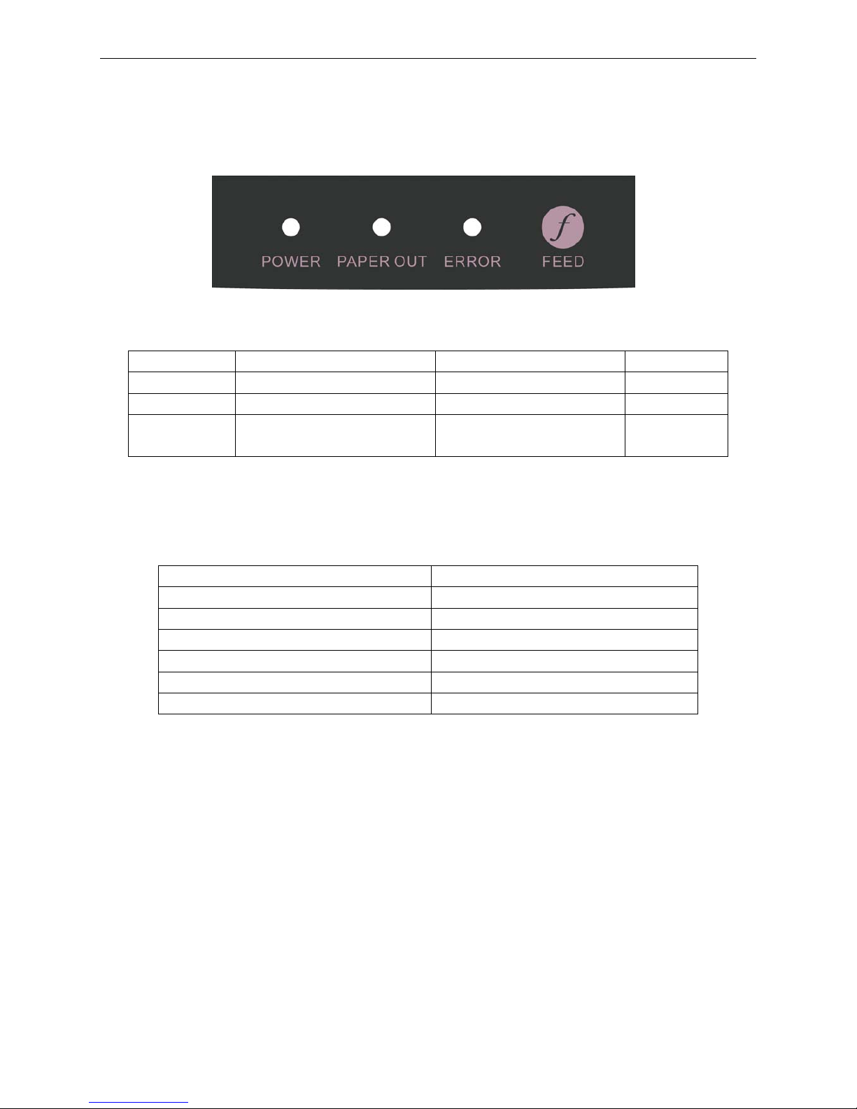
There are three LEDs and one key on the control panel as shown in Figure 3-1.
3.1.1 Indicator LEDs
3.1.2 Function Keys
While pressing the FEED key and holding on, turn on the printer at the same time. Loosen the FEED
key according to voice presentation times, and the printer will perform the following functions
correspondingly.
Voice presentation times Function Description
One beep Self-test
Two beeps print-pins test
Three beeps Alignment adjustment
Four beeps Hex dump mode
Five beeps Initialize the printer
Six beeps Aging test
Note: When there is paper in the printer, every time the FEED key is pressed (less than 0.5 second),
paper will feed one line. If you press and hold the key, the paper will feed continuously until
you release it.
3.2 Printer Parameter Settings
3.2.1 Current Settings of the Printer Parameter
Pressing down the FEED key while turning on the printer, loosen it when the printer beeps once.
Printer would print out the self-test sample, and the printer version and current settings are printed out
firstly.
LED On Blink Off
POWER
Power on
——
Power off
PAPER OUT
Paper out with alarm beep Paper is about to end Paper in
ERROR
Error occurs Print head is too hot and
protected
Normal status
Figure 3-1 Control panel
Page 32

BP-007 User’s Manual
- 27 -
3.2.2 Printer Setting Descriptions
PARAMETER ITEMS DESCRIPTION REMARK
BLACK MARK ON; OFF After selecting this function on, printer would
carry out black mark detect instruction so that
to make the vertical positioning printing
precisely. (Bills or papers should have black
mark on the surface.)
PRINT MODE BI-DIR; Select the printing direction of the print head:
Figure 3-2 BP-007 Default settings (Parallel and USB interface)
Figure 3-3 BP-007 Default setting (Serial interface)
BP-007 9Pin Mini Printer
VX.XX XXX XXXX-XX-XX
SN: XXXXXXXXXXXXXXXXXXXX
Cutter: OFF
Black Mark: OFF
Print Mode: BI-DIR
Paper Width: 76mm
CODEPAGE:
0:PC437
1:PC850
2:PC860
20:THAI(KU42)
21:THAI(TIS11)
26:THAI(TIS26)
BP-007 9Pin Mini Printer
VX.XX XXX XXXX-XX-XX
SN: XXXXXXXXXXXXXXXXXXXX
Cutter: OFF
Interface: RS-232
Baud Rate: 9600
Parity check: No
Data bit length: 8 bits
Stop bit: 1bit
Handshake: DTR/DSR
Black Mark: OFF
Print Mode: BI-DIR
Paper Width: 76mm
CODEPAGE:
0:PC437
1:PC850
2:PC860
20:THAI(KU42)
21:THAI(TIS11)
26:THAI(TIS26)
Page 33
BP-007 User’s Manual
- 28 -
UNI-DIR unidirectional or bidirectional
PAPER
WIDTH
76 mm; 57.5
mm
Specify the bill width of 76mm or 57.5mm.
INTERFACE RS-232 Specify the interface type. Only for Serial
interface model
BAUD RATE 9600 bps;
19200 bps
Specify the printer serial data transfer rate. Only for Serial
interface model
PARITY
CHECK
NO; EVEN;
ODD
Specify the parity bit for serial data transfer. Only for Serial
interface model
DATA BIT
LENGTH
8 BITS Specify the serial data bits. Only for Serial
interface model
STOP BIT 1 BIT Specify the serial data transfer stop bit. Only for Serial
interface model
HANDSHAKE DTR/DSR;
XOFF/XON
Specify the protocol of printer serial data
transfer as software control (XON/XOFF) or
hardware control (DTR).
Only for Serial
interface model
3.2.3 Parameter Settings
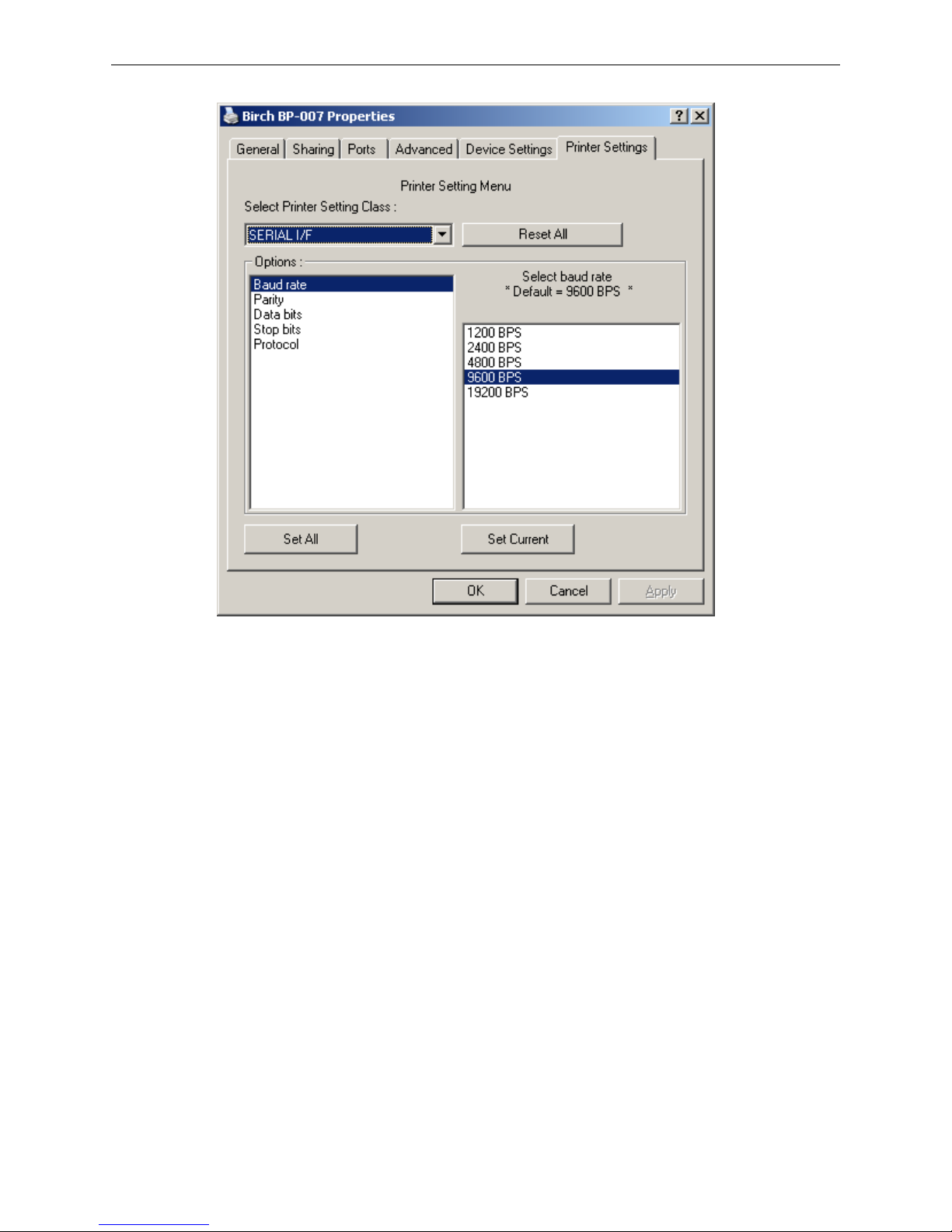
BP-007 supports the function of online-aptitude parameter settings, which can be set in the PC with the
driver installed in.
The concrete setting steps are shown as follows:
1. Make sure that the computer and the printer are connected with a cable and both the computer and
the printer are turned on, the printer should be in normal working condition as well.
2. Click “Start” → “Settings” → “Printers”.
3. Right click “BP-007”, select “Properties”.
4. Click “Printer settings” in the property page.
Page 34
BP-007 User’s Manual
- 29 -
5. In the window of “Printer Settings”, select parameter types in the Printer Setting Class, then select
the parameter items in the Options list. At last, select the parameter in the right column.
6. Click “Reset All” to recover all the parameter to the default settings and does not change the printer
parameter settings.
7. When setting parameter, you could click “Set Current” to save the current value after setting every
item. Also, you could click “Set All” to save the all the parameter values after setting all items. After
clicking “Set All” or “Set Current”, program would set the setting command to the printer.
8. Printer would change the parameter settings as soon as it receives the setting command. It is no
need to reboot the printer.
9. After finishing setting, click “OK” to exit the “Properties” window.
3.3 Self-Test Function
■ Self-Test Mode
While pressing the FEED key and holding on, turn on the printer. The printer would beep once,
then loosen the key, the printer would enter self-test mode.
■ Print-Pins Test
While pressing the FEED key and holding on, turn on the printer. The printer sounds two beeps,
and you should loosen the FEED key at the same time. The printer will enter the print-pins test.
Page 35

BP-007 User’s Manual
- 30 -
■ Mode of Alignment Adjusting
While pressing the FEED key and holding on, turn on the printer. The printer sounds three beeps,
and you should loosen the FEED key at the same time. The printer will print the degree of
alignment adjusting.
Each press the FEED key will add 1 to the original value. If you select BID 08, press FEED key for
8 times, and then press this key for a long time, it will be saved after sounding two beeps, and the
present selected value will be printed at the same time. Turn off the printer; the new value will be
active after the printer is restarted.
NOTE: Adjustment of alignment will affect printing quality. You must think carefully before
adjusting and must operate strictly according to instruction.
■ Hex Dump Mode
While pressing the FEED key and holding on, turn on the printer. The printer sounds four beeps,
and you should loosen the FEED key at the same time. The printer will enter the Hexadecimal
Printing Mode.
Page 36
BP-007 User’s Manual
- 31 -
Chapter 4 Installing Paper
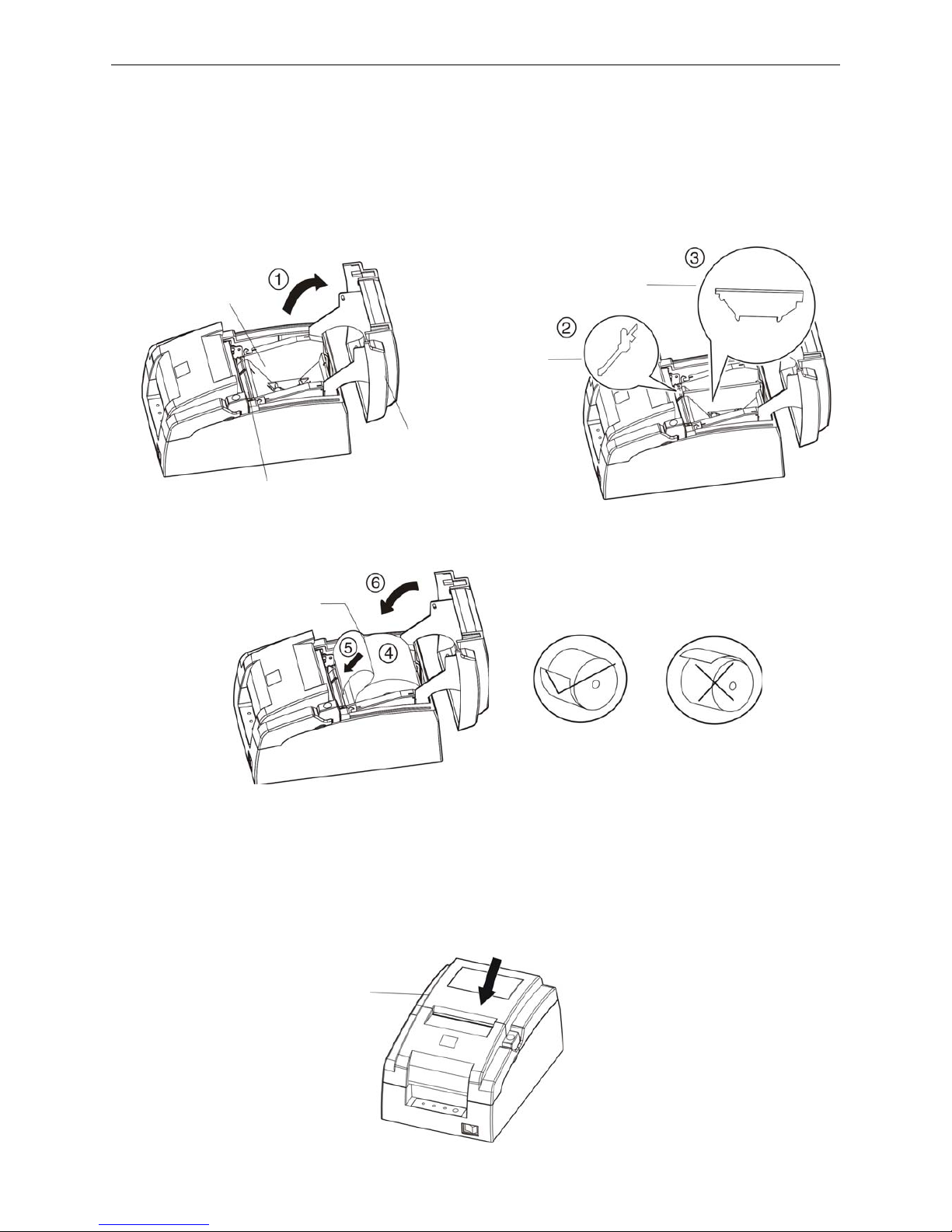
The printer can use the paper with the width of 76±0.5mm or 57.5±0.5mm, and it is easy to load paper.
How to load paper will be introduced in this chapter.
1. Press the cover-open button to open the upper cover. If you want to use 57.5mm paper to print, you
must install the 57.5mm paper stopper_mechanism and 57.5mm paper stopper_holder.
2. Place the roll paper into the paper holder.
Note: Paper head should be pulled out by the direction of p aper-input slot, but not the opposite.
3. Turn on the printer, and then hold both edges of the paper and insert it straight into the paper-input slot
until the paper is fed automatically.
Note: Paper head must be even, or the paper cannot be fed. If this phenomenon happens, you
must pull out paper head and cut evenly the paper head, and load paper once again.
4. Close the upper cover and press FEED key to adjust the printing home position.
Correct
Error
Paper-input Slot
Upper Cover
Paper Holder
Roll Pape
r
Upper Cover
57.5mm Paper
stopper_Mechanism
57.5mm Paper stopper_Holder
Page 37
BP-007 User’s Manual
- 32 -
Chapter 5 Specifications
5.1 Basic Specifications
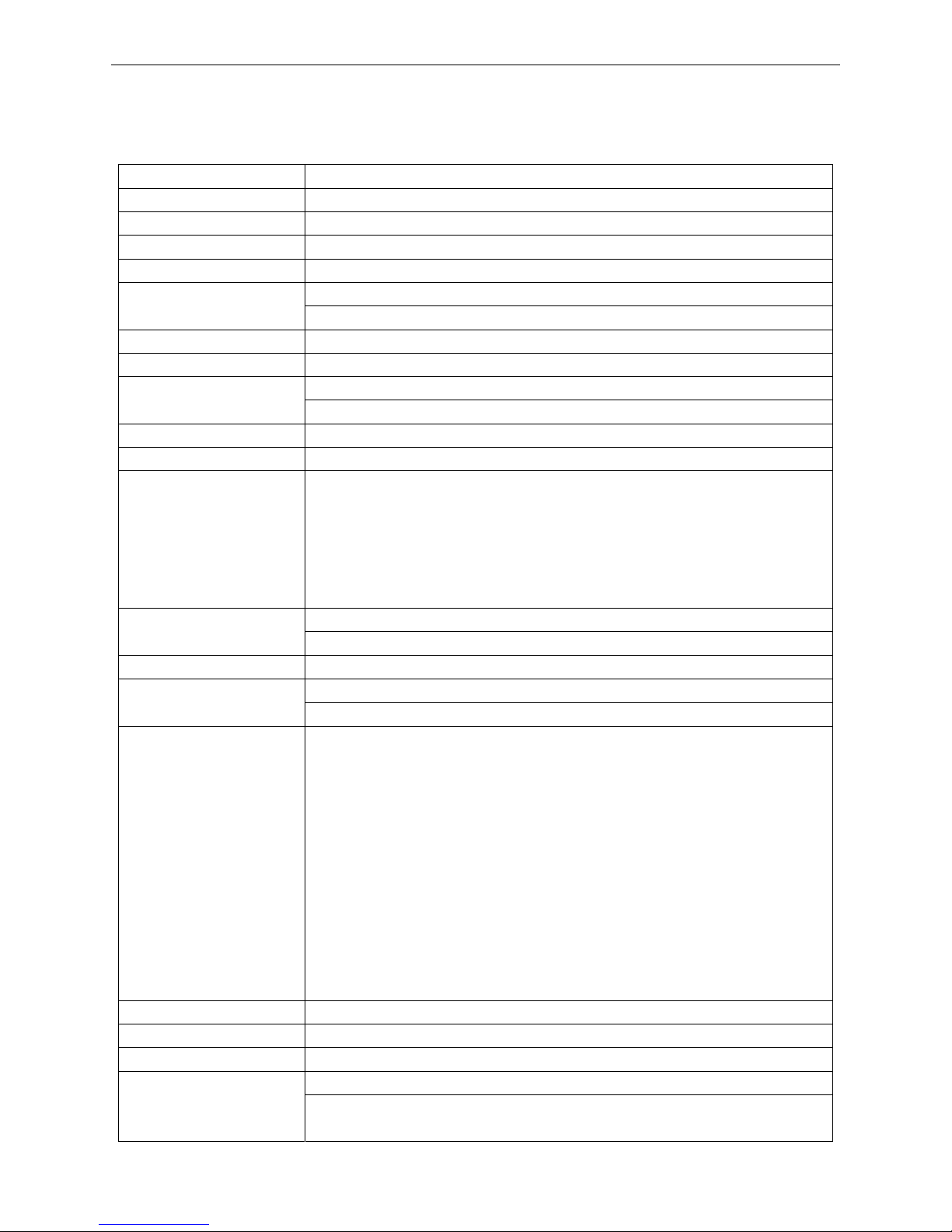
Item Description
Printing method 9 Pins Dot matrix impact
Printing direction Bidirectional logic seeking
Diameter of wire 0.3mm
Dot density 160×144DPI (maximum)
Standard Auto-cutter
Cuttable thickness:0.065 ~ 0.075mm
Print speed: 4.7lines per second (paper width 76mm, 40 columns);
Copy 3 pieces (Original + 2 copies)
MCBF: 12 million lines Reliability
Print Head Life: 400 million dots/wire (200 million characters)
Effective printing width 63mm
Paper feed speed 140mm/s (Max.)
Paper Specifications
Paper Width: 57.5 ±0.5 mm, 76 ±0.5 mm
Paper Weight: 52.3~64.0 g/m
2
Paper Thickness: 0.06~0.20mm
Diameter of paper: Φ83mm max.
Inner Diameter of paper shaft: Φ12mm min.
Outer Diameter of paper shaft: Φ18mm max.
ASCII character set, International character set Character set
Big 5 or GB 18030
Line spacing 1/6 inch, or by programmable in 1/144 inch increments
Type: Compatible star RC 200B Ribbon
Life: 3 million characters
Interface types
Cash drawer interface + data interface (parallel interface, USB interface,
serial interface, USB interface + Ethernet interface, Bluetooth or USB
interface & Wi-Fi)
Cash drawer interface: RJ-11, DC24V/1A
Parallel interface: Centronics
Serial interface: RS-232C (DB25)
USB interface: 2.0 Full-speed
USB interface + Ethernet interface: 2.0 Full-Speed, 10/100Base-T
Bluetooth: 2.0/2.1 + EDR
USB interface + Wi-Fi: 2.0 Full-Speed , 802.11b/g/n
Note: Only one of the data interfaces is supplied when leaving the
factory. (According to the specific interface standards.)
Black mark Standard
Special function Online parameter settings, Software online upgrade
Buffer memory 60KB
ESC/POS Emulation Control command
Character printing command: Support ANK characters, user-define
characters and enlarge Chinese characters 1-2 times printing, can adjust
Page 38
BP-007 User’s Manual
- 33 -
character line spacing
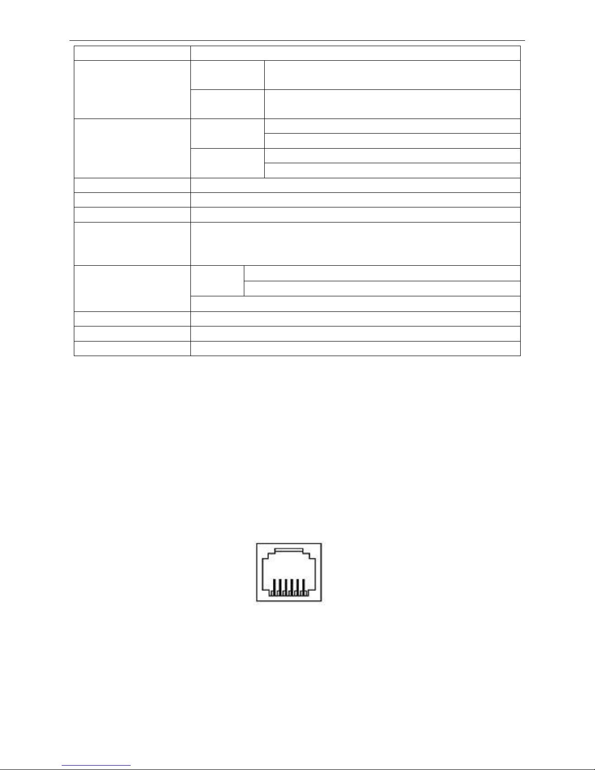
Input
Voltage: 100-240V AC
Frequency: 50Hz/60Hz
Power supply
Output
Voltage: 24V DC
Current: 2.5A
Temperature: 5 ~ 40℃
Operating
environment
Humidity: 20%RH ~ 80%RH (No condensation)
Temperature: -40 ~ 55℃
Environmental condition
Storage
environment
Humidity: ≤93%RH (40℃, No condensation)
Weight Approx. 2.1 kg (with auto-cutter)
Noise
<58 dB (A) (ISO7779 standard)
Physical dimensions 156mm(Width) × 236mm(Depth) × 131mm(Height)
Power Operation power: 20W; Max. power: 48W; Standby power: 3.2 W.①②③
Note: Only when the product doesn’t connect any power supply, can it
consume zero energy.
300 dots per line (57.5±0.5mm paper width)
Horizontal
420 dots per line (76±0.5mm paper width)
Resolution
Vertical: 144DPI
Control panel 1 key and 3 indicator lights
Paper type Roll paper
Wireless disturb Grade B
Note: The Print head life and MCBF above are realized by using appointed printing paper and ribbon
cartridge in the environment appointed by BIRCH PRINTER.
5.2 Interface
This printer is equipped with one data interface (parallel interface, serial interface, USB interface, USB
interface + Ethernet interface, Bluetooth or USB interface + Wi-Fi) and one cash drawer interface.
Connect the computer with correct cables.
5.2.1 Cash Drawer Interface
(1) The cash drawer interface is RJ-11 interface (6 lines), shown as below.
(2) Definition of pins
The definition of the cash drawer interface pins is shown as the Table below:
Figure 5-1 Cash drawer interface
6 1
Page 39
BP-007 User’s Manual
- 34 -
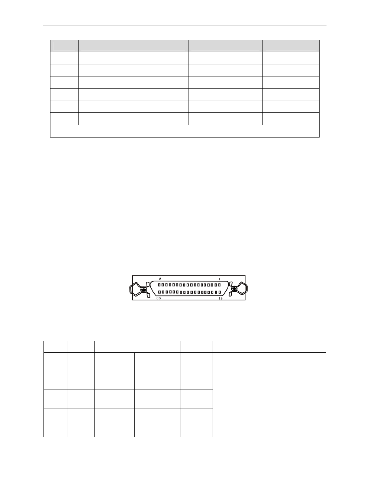
Table A-1 Definition of the Cash drawer Connector Pins
Pin NO. Signal Name Electric Characteristic Signal Direction
1 Frame GND
2 Cash drawer drive signal DC24V/1A Output
3 Cash drawer Open/close signal TTL Input
4 24VDC Power
5 NC
6 Cash drawer Open/close signal GND
Drive current≤24V/1A
Note: Please use the proper cash drawer. Manufacturer will not honor warranty when using
improper cash drawer.
5.2.2 Parallel Interface
(1) Technology specifications
a) Select pulse: Pulse is supplied from exterior/STROBE.
b) Signal exchange: /ACK (answer) and BUSY (busy).
c) Logic electric level: All the input data and interface control signal are compatible with TTL electric
level.
(2) Linker
Parallel interface is 57-30360 (AMPHENOL). The parallel interface connector is 36PIN type, shown
as Figure 5-2.
(3) Definition of pins (as shown in table A-2)
Table A-2 Pin function of parallel interface connector
Pin return Signal name Direction Description
1 19 /STROBE Data selected IN
Width of selected pulse is 0.5 µ sec.
2 20 DATA1 Date bit 1 IN / OUT
3 21 DATA2 Date bit 2 IN / OUT
4 22 DATA3 Date bit 3 IN / OUT
5 23 DATA4 Date bit 4 IN / OUT
6 24 DATA5 Date bit 5 IN / OUT
7 25 DATA6 Date bit 6 IN / OUT
8 26 DATA7 Date bit 7 IN / OUT
9 27 DATA8 Date bit 8 IN / OUT
Means 8 bits of parallel data signal. High
level means logical “1”, low level means
logical “0”.
Figure 5-2 Pins number of the parallel interface connector
Page 40

BP-007 User’s Manual
- 35 -
10 28 /ACK Answer out OUT
Pulse width is about 12µ sec. Low level
means that data is received and the
printer is ready for receiving more data.
11
29
BUSY Printer state OUT
High level out means that printer is busy
and can’t receive data. High level is out
from this pin on the following condition:
1. When data is being imported;
2. At the time of printing;
3. When the printer is offline;
4. When error happens.
12 30 PE Paper out OUT High level means paper out.
13 SLCT
Printer is
selected
OUT
High level (5V) with the 3.3KΩpull-up
resistor.
14
/AUTOFEED Auto feed IN
At low level, the printer will change to the
next line to print automatically after one
line printing is finished.
15 NC Empty pin --- This pin is empty.
16 GND Logical ground --- Logical ground
17 CHASSIS
Structure
ground
---
It is structure ground of printer, and is
separated from logical ground.
18 NC Empty pin --- This pin is empty.
19~
30
GND Ground ---
Loop ground that is twisted with signal
line.
31 16 /INIT
Initialization of
printer
Input
Low level means initialization of printer
32 /ERROR
Error happens
with printer.
Out
When the printer is in state of paper out,
offline condition or error, this signal level
becomes low.
33 GND Ground ---
Same with 19~30 pins.
34 NC Empty pin --- This pin is empty.
35 +5V +5V supply Out
Pull up to 5V by the 3.3K Ω pull-up
resistor.
36 /SLCTIN
Printer is
selected and
answered.
In
Only when this signal level is low, can
the data be put into the printer.
The “direction” in the title panel means the flow direction of printer signal to the printer.
“Return” in the title panel means returning by pair-twist. You must confirm that the interface
cable is pair-twist shielding line, and every signal line is looped with ground line and pair-twisted
together. Shielding line should be connected with the frame ground of host computer and
printer.
All the interface condition is based on TTL level. The rising and falling time of signal must be
less than 0.2 ms.
The data transfer must comply with the specification of ACK or Busy signal. Only when the level
of ACK or Busy signal is low can data be transferred.
Page 41
BP-007 User’s Manual
- 36 -
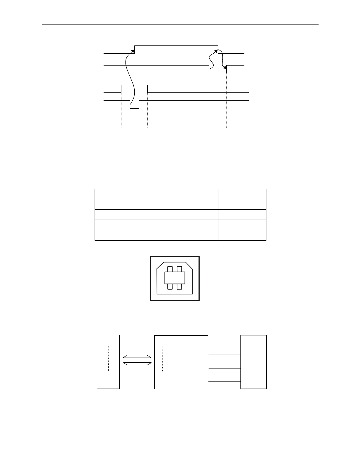
(4) Time sequence of Parallel to transmit data (as shown by Figure 5-3):
5.2.3 USB Interface
1. The USB interface connector is USB-B type (as shown by Figure 5-4):
USB interface is 2.0 Full-Speed version.
Contact Number Signal Name Color
1 VBUS Red
2 D- White
3 D+ Green
4 GND Black
2. The connecting figure of printer and computer with USB interface (as shown in Figure 5-5).
USB Interface is 2.0 Full-Speed interface, and displayed as a USB port on the computer finally. You
can use the
USB Interface to print by selecting corresponding USB port.
BUSY
/
ACK
DAT
/
STR
0.5
μs
0.5
μs
0.5
μs
5μs5
μs
Figure 5-3 Time sequence of parallel to transmit data
Figure 5-4 USB-B type connector
Figure 5-5 Connecting figure of printer and computer with USB interface
2 1
3 4
D0
D7
VBUS
GND
D+
D-
D0
PDIUSBD12
D7
Printer’s 26PIN connector
PDIUSBD12 chip
USB-B connector
Page 42

BP-007 User’s Manual
- 37 -
5.2.4 Serial Interface
(1) Serial interface is RS-232 type and the connector type is DB-25.
The DB-25 connector is shown as Figure 5-6.
(2) Connecting figure of printer and computer with serial interface
The figure is shown as follows:
(3) Definition of pins
Definition of each pin of RS-232 serial interface is shown in Table A-3:
Table A-3 Definition of pins of RS-232 serial interface
Pin NO. Signal name Signal Direction
1 FG Frame GND
2 TXD Data output Output
3 RXD Data input Input
4 RTS Ask for Sending Output
5 CTS Allowable to Send Input
6 DSR Data Set Ready Input
7 GND power GND
8 DCD Data Carrier Detect Input
……
20 DTR Data Terminal Ready Output
……
(4) Interface protocol
1. DTR/DSR interface protocol
The DTR from the printer controls the data flow between the printer and Host. When the DRT is
high level means the printer is FREE and it can receive the data from the Host. DTR is High level
when it belongs to the following three conditions:
Figure 5-7 Connecting figure of printer and computer with serial interface
Host computer’s 9PIN connector
Print
e
r’s 25PIN connect
or
DTR
GND
TXD
RXD
DSR
DCD
CTS
GND
RXD
TXD
20
7
2
3
5
2
3
6
1
8
Figure 5-6 Pin number of the serial interface connector
Page 43
BP-007 User’s Manual
- 38 -
The printer is ONLINE
The available memory of data buffer is larger than limited value.
The printer has no error.
When the DTR is Low level means the printer is BUSY and it can’t receive the data from the Host.
DTR is Low level when it belongs to the following three conditions:
The printer is OFFLINE
The available memory of data buffer is less than limited value.
The printer has error
2. X-ON/X-OFF communication protocol
When the printer sends X-ON (11H) code to the Host through TXD, it means the printer is FREE
and it can receive data from the Host. When the available memory of the printer’s data buffer is
greater than limited value, the printer can send the X-ON code when it is in the following two
conditions:
The printer becomes FREE from BUSY
The printer becomes ONLINE from OFFLINE
When the printer sends X-OFF (13H) code to the Host through TXD, it means the printer is BUSY
and it can’t receive the data from the Host. The printer can send the X-OFF code when it is in the
following conditions:
The printer becomes BUSY from FREE
The printer becomes OFFLINE from ONLINE
The available memory of the printer’s data buffer is less than limited value
The printer has error
The printer is out of paper
(5) Serial data receive/send format
The serial data is consisted of original bit (1 bit), data bit (8 bits), check bit (1 bit) and stop bit (1 bit).
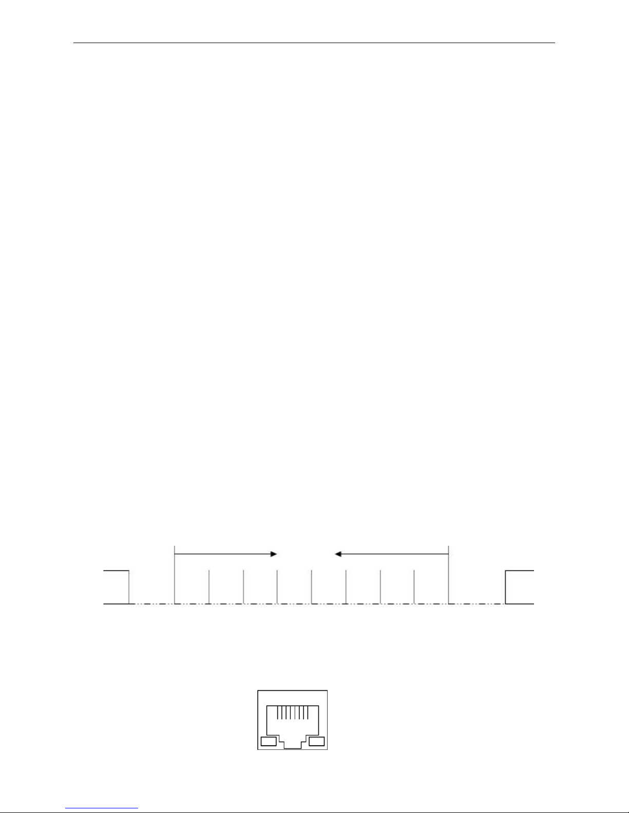
(As shown in figure 5-8)
5.2.5 Ethernet Interface
10/100Base-T Ethernet interface can connect to 10/100M Ethernet.
Figure 5-9 Ethernet interface
Figure 5-8 Serial data format
Original bit D1 D2 D3 D4 D5 D6 D7 D8 Check bit
Stop bit
Data bit
Page 44
BP-007 User’s Manual
- 39 -
5.3 Auto-cutter Specification
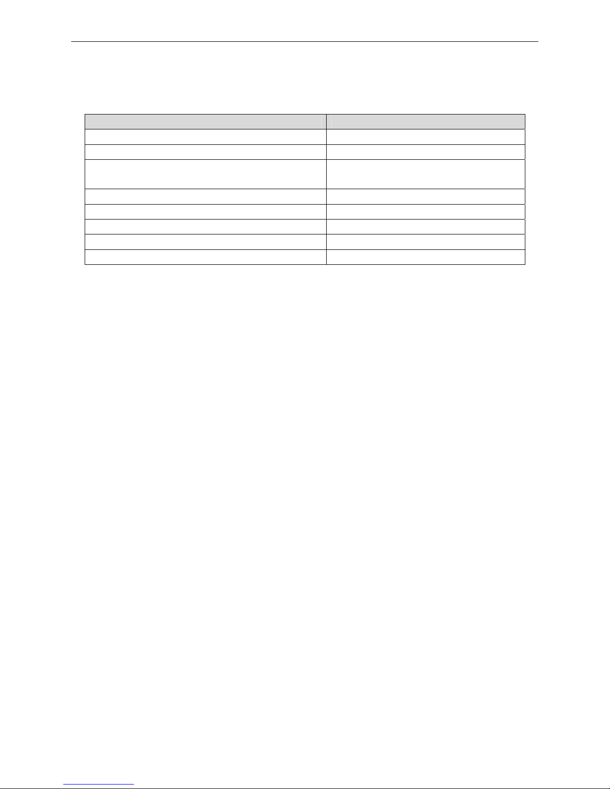
BP-007 is equipped with an auto-cutter, which parameter is shown as table A-4:
T able A-4 Auto-cutter Specification
Item Specification
Paper width 85mm (max.)
Cuttable thickness
Paper thickness: 65~75 µm
Cutting mode
Full cut or partially cut leaving point (one
point, 2mm)
Drive voltage (V) Motor: 24±2.4, detector: 3.3±0.165
Startup current (A) 1.2 (max.)
Operating time (second/ cut period) 500 (max.)
Cutting frequency (cuts/minute) 30 (max.)
Physical dimensions (length × width × height) (mm) 100×52×15
Page 45
BP-007 User’s Manual
- 40 -
Chapter 6 Troubleshooting and Maintenance
6.1 Clean the Printer
It’s necessary to clean the printer periodically.
Cleaning periodically and the cleaning tool
Periodically cleaning: every six months or every 300 working hours once
Cleaning tool: dry cloth (please use soft cloth to clean metal parts.)
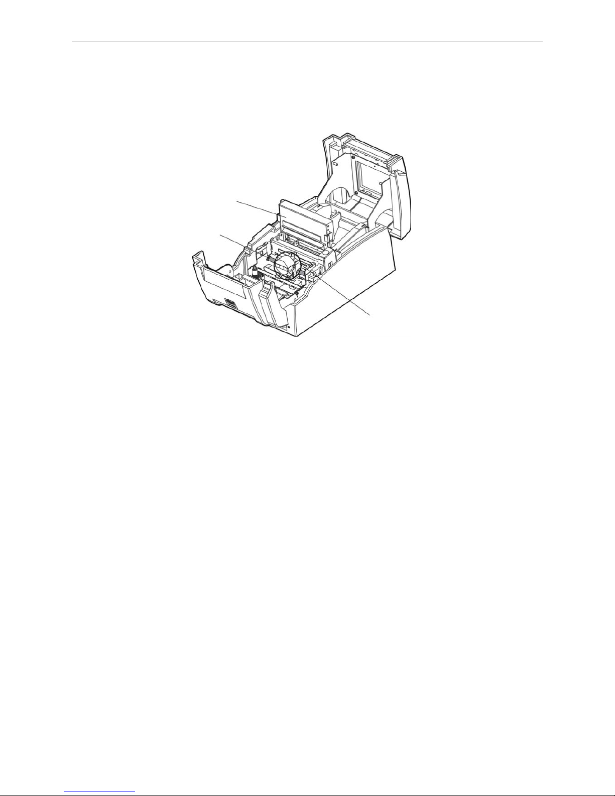
Cleaning the paper channel and spare parts under carriage
Wipe off wasted paper and clean dirt and dust.
Cleaning the carriage shaft
There is a layer of oil covered on the carriage shaft which guarantees the carriage runs smoothly. But the oil
is easy to absorb dust, please clean the dust with soft cloth first, and then add proper lube (NYE180 lube of
NYE Company is recommended), move print head back and forth to make lube scattered.
Note: 1. Turn off printer and pull out the power cord before cleaning.
2. Being used under dust circumstance, the carriage shaft may stack much dust and affect the
print quality.
3. Do not touch the print head if the printer has just been used as the print head may be hot.
4. Don't use hard cloth or flammable solvent to clean the printer.
6.2 Problems and Solutions
(1) Turn on the printer, all LEDs are off, and printer has no action
Make sure that the printer is connected to the power, and check whether the power cable and
electrical outlet are working normally.
(2) Self-test is ok, but online is disabled
Figure 6-1 Cleaning the printer
Carriage Frame
Carriage shaft
Auto-cutter Assembly
Page 46

BP-007 User’s Manual
- 41 -
① Please make sure that the printer is connected with the computer correctly and the paper is loaded
well.
② If it can't print with online function all the time, please replace the interface cable with a new one.
(3) Paper out
① Phenomenon: Paper out LED is on and cannot print;
Or the printing action stops suddenly while printing, and paper out LED is on; and at
the same time the alarm voice is presented by the printer.
Reason: Paper out
Solution: Install the roll paper again, then, press FEED key, printer would enter into Online mode from
Offline mode and it would resume normal.
② Phenomenon: Paper out LED is blinking.
Reason: Paper is about to use up.
Solution: Prepare to install new roll paper.
(4) Print head overheat protection
Phenomenon: The print head move, but not print, ERROR LED blinks.
Reason: The temperature of the print head is too hot, and it enters the protect state.
Solution: Please wait patiently; the printer will recover automatically after the print head cools down.
(5) Print quality
①Phenomenon: The printer can't print at all.
Solution: 1. Check the ribbon cartridge is installed correctly.
2. Make sure that the interface cable is connected correctly.
②Phenomenon: The printed characters are feint
Solution: Remove the ribbon cartridge and turn the ribbon knob, then install it again. If the printed
characters are still feint, please replace a new one.
③Phenomenon: One line prints only one character, or the spacing between characters is too large.
Solution: Initialize the printer and make it come back to factory default setting.
Method: Pressing the FEED key, and turn on the printer at the same time, when you hear it sound 5
beeps, loosen the FEED key, the printer is initialized automatically.
(6) Print character
Phenomenon: The printer can’t print the appropriate characters.
Solution: Make sure the driver is installed correctly, and the character format you selected in the
application is the appropriate format.
Page 47

BP-007 User’s Manual
- 42 -
Chapter 7 Command Code Summary
7.1 General
The BP-007 printer‘s control commands are compatible with ESC/POS.
Explanation of every command contains format and description. “Format” parts give three kinds of
command format, including ASCII Code, Decimal code and hexadecimal code. “Description” parts
describe the function of command. These three kinds of command format are equivalent, and you can
select anyone by your need.
The explanation format of these commands is shown as following:
Command Function
Format: ASCII: Indicates the ASCII equivalents
Decimal: Indicates the decimal equivalents
Hex: Written in hexadecimal code
[Description]
Describing the function and using instruction of this command.
7.2 Explanation of Command
HT Horizontal tab
Format: ASCII: HT
Decimal: 9
Hex: 09
[Description]
Moves the print position to the next horizontal tab position.
If the current printing position exceeds the last horizontal tab position, the HT command will not be
executed.
Horizontal tab positions are set by “ESC D” command.
LF Print and line feed
Format: ASCII: LF
Decimal: 10
Hex: 0A
[Description]
Prints one line data in the line editing buffer and feeds one line based on the current line spacing.
If the line editing buffer is empty, then only feeds one line based on the current line spacing without printing.
CR Print and carriage return
Format: ASCII: CR
Decimal: 13
Hex: 0D
[Description]
The printer prints one line data in the line editing buffer and the print head returns to the left position
automatically.
Page 48
BP-007 User’s Manual
- 43 -
FF Print and change page
Format: ASCII: FF
Decimal: 12
Hex: 0C
[Description]
Prints one line data in the line editing buffer and feeds to the top of next page based on the current page
length.
ESC SP Set right-side character spacing
Format: ASCII: ESC SP n
Decimal: 27 32 n
Hex: 1B 20 n
[Description]
Sets the right-side character spacing to n times of half dot spacing (1/144 Inch).
n=0~32; Default n=0.
ESC ! Set character printing mode
Format: ASCII:
ESC ! n
Decimal: 27 33 n
Hex: 1B 21 n
[Description]
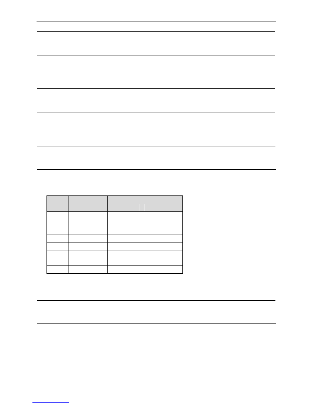
“ESC ! n” is synthetic setting command for character printing mode, and is used for selecting size
and underline of printed character. The bit definition of print parameter “n” is shown as follows:
Default n=1. That means: 7×7 dot array, normal character size and no underline.
ESC % Select/cancel user-defined character set
Format: ASCII: ESC % n
Decimal: 27 37 n
Hex: 1B 25 n
[Description]
Parameter n is one byte, and only the lowest bit is valid.
When n=<*******1>B, the user-defined character set is selected.
When n=<*******0>B, the inner character set is selected.
When 0≤n≤255, default n=0.
Value
Bit Function
0 1
0 Character font 5×7 7×7
1 undefined
2 undefined
3 undefined
4 Double-height Canceled Selected
5 Double-width Canceled Selected
6 undefined
7 Underline Turned off Turned on
Page 49
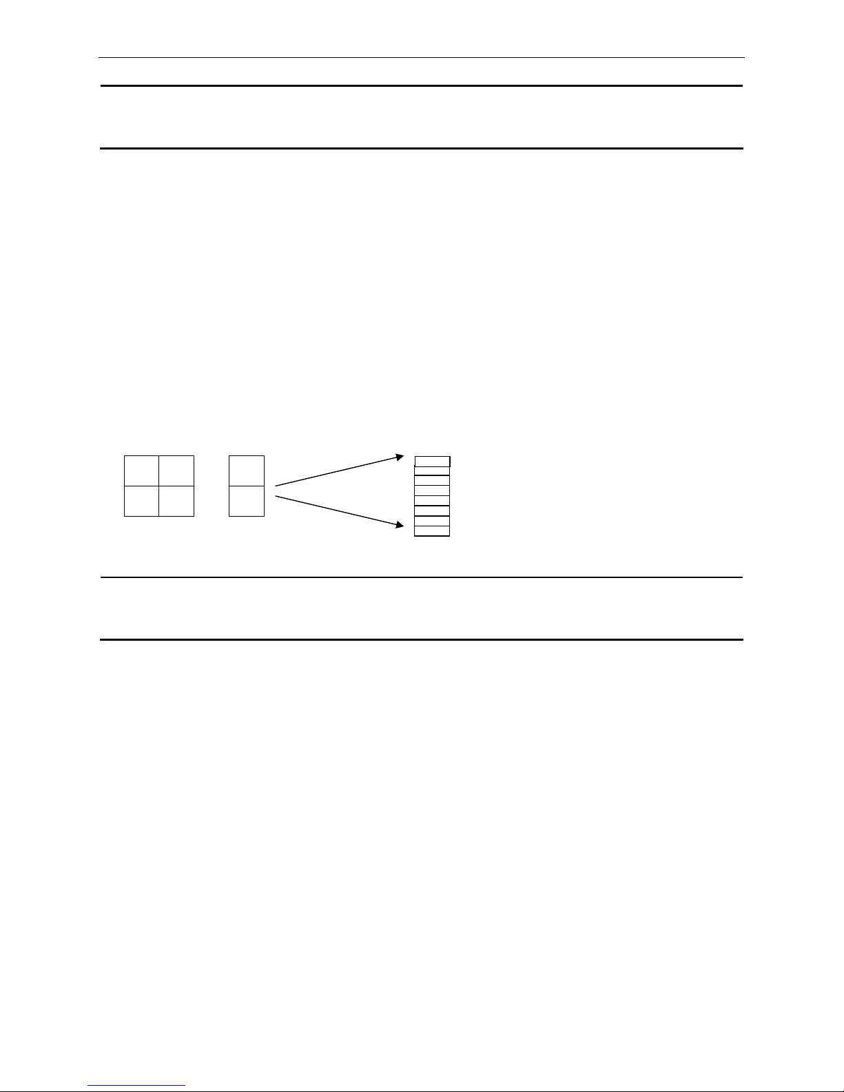
BP-007 User’s Manual
- 44 -
ESC & Define user-defined characters
Format: ASCII: ESC & s n m a d1 d2……db
Decimal: 27 38 s n m a d1 d2……db
Hex: 1B 26 s n m a d1 d2……db
[Description]
This command is used for self-defining characters. The meaning of each parameter is shown as follows:
S: The number of longitudinal byte. Here S=1, 2. When n=1, define 7×7 character.
When n=2, define 7×9 or half-size character.
N: Starting ASCII code of user-defined character set. n≥32.
M:
Ending ASCII code of user-defined character set. m≤127. The number of user-defined
characters is m-n+1, and the maximum number is 96. When user defines only 1
character, m=n.
A: The byte number of user-defined characters.
d1 d2…db:
The data of user-defined characters. Every character has s×a bytes. m-n+1 bytes
altogether have (s×a) × (m-n+1) bytes.
The user-defined characters after being defined will be valid all the time until they are
defined again or the printer is turned off.
The format of user-defined characters is shown as follows:
d1 d4 …
d2 d3 …
ESC * Select bit-image mode
Format: ASCII:
ESC * m n1 n2 [d]n1+256×n2
Decimal:
27 42 m n1 n2 [d]n1+256×n2
Hex:
1B 2A m n1 n2 [d]n1+256×n2
[Description]
This command is used for setting dot matrix figure mode (m) and setting the transverse dots number (n1,
n2) of dot matrix figure.
m=0, 1
0≤n1≤255, 0≤n2≤3, 0≤d≤255.
n1, n2 is hexadecimal figure with two bits. n1 is low byte and n2 is high byte. n1, n2 is used for denoting the
transverse dots number of figure printed by “ESC *” command. This value should be within the number of
maximum line-width dots.
When m=0, normal printing is selected, the maximum number of printing dots is 210.
When m=1, half-dot printing is selected, the maximum number of printing dots is 420. On this condition the
adjacent dots cannot be “1” at the same time.
The definition of [d] is:
b7
Page 50
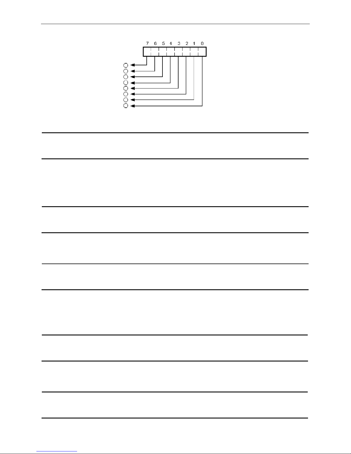
BP-007 User’s Manual
- 45 -
ESC - Turn underline mode on/off
Format: ASCII: ESC - n
Decimal: 27 45 n
Hex: 1B 2D n
[Description]
n=0, turns off underline mode; n=1, turns on underline mode.
ESC 2 Set 1/6 inch line spacing
Format: ASCII: ESC 2
Decimal: 27 50
Hex: 1B 32
[Description]
Set the line spacing to 1/6 inch.
ESC 3 Set n/144 inch line spacing
Format: ASCII: ESC 3 n
Decimal: 27 51 n
Hex: 1B 33 n
[Description]
Set the line spacing to n/144 inch.
n=0~255.
Default: n=24.
ESC < Print head Returns to standby position
Format: ASCII: ESC <
Decimal: 27 60
Hex: 1B 3C
[Description]
This command makes the print head move to the standby position.
ESC ? n Cancel user-defined characters
Format: ASCII:
ESC ? n
Decimal: 27 63 n
Hex: 1B 3F n
[Description]
Bit image data
The first pin
The eighth pin
Print data
Page 51

BP-007 User’s Manual
- 46 -
Cancel he user-defined character “n”. This command function can be canceled only after the computer
being restarted.
ESC @ Initialize printer
Format: ASCII:
ESC @
Decimal: 27 64
Hex: 1B 40
[Description]
This command is used for initializing the printer, and its function is described as follows:
(1) Clearing the data in the print buffer and line-editing buffer.
(2) Resuming the default value.
(3) Setting the printing mode of Chinese character.
(4) Deleting user-defined characters.
ESC C Set the page length according to line spacing
Format: ASCII: ESC C n
Decimal: 27 67 n
Hex: 1B 43 n
[Description]
The command sets the length of detecting black mark in the meantime. If the black mark can’t be detected
in this length, then it is considered that the paper has no black mark.
The specified page length = current line spacing* n.
ESC D Set horizontal tab positions
Format: ASCII: ESC D n[k] NULL
Decimal: 27 68 n[k] 0
Hex: 1B 44 n[k] 00
[Description]
Set horizontal tab positions to n1, n2, …, nK.
For BP-007, k=1~21, and it can set 21 horizontal tab positions at most.
The absolute horizontal position of the first horizontal tab is: n1 times of half-dot distance;
The absolute horizontal position of the second horizontal tab is: (n1+n2) times of half-dot distance;
The absolute horizontal position of the third horizontal tab is: (n1+n2+n3) times of half-dot distance;
……
The absolute horizontal position of the Kth horizontal tab is: (n1+n2+n3+……+nK) times of half-dot
distance;
Default value: n1=n2=……=nK=10.
All the horizontal tab positions (ni) should be within the line width allowed by the printer. ni=1~80, it is equal
to 40 7×7 or 7×9 dot matrix characters width, or equal to 20 16×15 Chinese characters width.
After executing “ESC D” command, changing the kind and size of characters will not affect tab positions
already set. This can guarantee that tab is put in order when Chinese characters are confused with
common characters in one line, or when characters are magnified or shrinked.
NUL put in the end means that this command is over.
ESC E Set / Cancel boldface printing
Format: ASCII: ESC E n
Decimal: 27 69 n
Hex: 1B 45 n
[Description]
This command realizes boldface printing by printing twice in which 2nd printing shifts little rightwards from
1st printing.
• When n is 0, boldface printing is invalid.
• When n is 1, boldface printing is valid.
Page 52

BP-007 User’s Manual
- 47 -
ESC G Turn double-strike mode on/off
Format: ASCII: ESC G n
Decimal: 27 71 n
Hex: 1B 47 n
[Description]
When double-strike mode is turned on, the same character will be printed twice in the same position.
• When n is 0, double-strike mode is turned off.
• When n is 1, double-strike mode is turned on.
ESC J
Print and feed paper
Format: ASCII: ESC J n
Decimal: 27 74 n
Hex: 1B 4A n
[Description]
Print the data in the print buffer and feeds the paper by n/144 inch. If there is no content in buffer, the printer
will feed paper directly without printing.
ESC K Print and feed reversely
Format: ASCII: ESC K n
Decimal: 27 75 n
Hex: 1B 4B n
[Description]
Print the data in the print buffer and feeds the paper by n/144 inch in the reverse direction.
n=0~48.
ESC U Turn unidirectional printing mode on/off
Format: ASCII: ESC U n
Decimal: 27 85 n
Hex: 1B 55 n
[Description]
Turn unidirectional print mode on or off. n=0~255, only the lowest bit is valid.
When n=<*******1>B, unidirectional printing mode is set.
When n=<*******0>B, bidirectional printing mode is set.
[Default] n = 0.
ESC c 4 n Select paper sensor to stop printing
Format: ASCII: ESC c 4 n
Decimal: 27 99 52 n
Hex: 1B 63 34 n
[Description]
Select the paper sensor to stop printing when a paper end is detected.
n=0~255.
n=05H, selects the paper sensor to stop printing when a paper end is detected.
n=0, when a paper end is detected, printing is not stopped, so that user can print the last bill to the page
end.
[Default] n = 05H.
Page 53

BP-007 User’s Manual
- 48 -
ESC c 5 n Enable/disable panel buttons
Format: ASCII: ESC c 5 n
Decimal: 27 99 53 n
Hex: 1B 63 35 n
[Description]
Enable or disables the panel buttons.
• When n=<*******0>B, all buttons are enabled (Default).
• When n=<*******1>B, all buttons are disabled.
ESC d Print and feed n lines
Format: ASCII: ESC d n
Decimal: 27 100 n
Hex: 1B 64 n
[Description]
Print the data in the print buffer and feeds n lines.
n=0~255.
ESC e Print and feed reversely n lines
Format: ASCII: ESC e n
Decimal: 27 101 n
Hex: 1B 65 n
[Description]
Print the data in the print buffer and feeds n lines in the reverse direction.
n=0~2. The maximum reverse paper feed spacing is 48 dots (48*0.176mm).
ESC i Full cut
Format: ASCII: ESC i
Decimal: 27 105
Hex: 1B 69
[Description]
Execute a full cut of the paper roll by auto cutter.
ESC j Print and feed reversely
Format: ASCII: ESC j n
Decimal: 27 106 n
Hex: 1B 6A n
[Description]
Print the data in the print buffer and feeds the paper in the reverse direction by 1/144 inch.
If there is no data in the print buffer, the printer will feed paper directly. n=0~48.
ESC m Partial cut
Format: ASCII: ESC m
Decimal: 27 109
Hex: 1B 6D
[Description]
Execute a partial cut of the roll paper.
Page 54
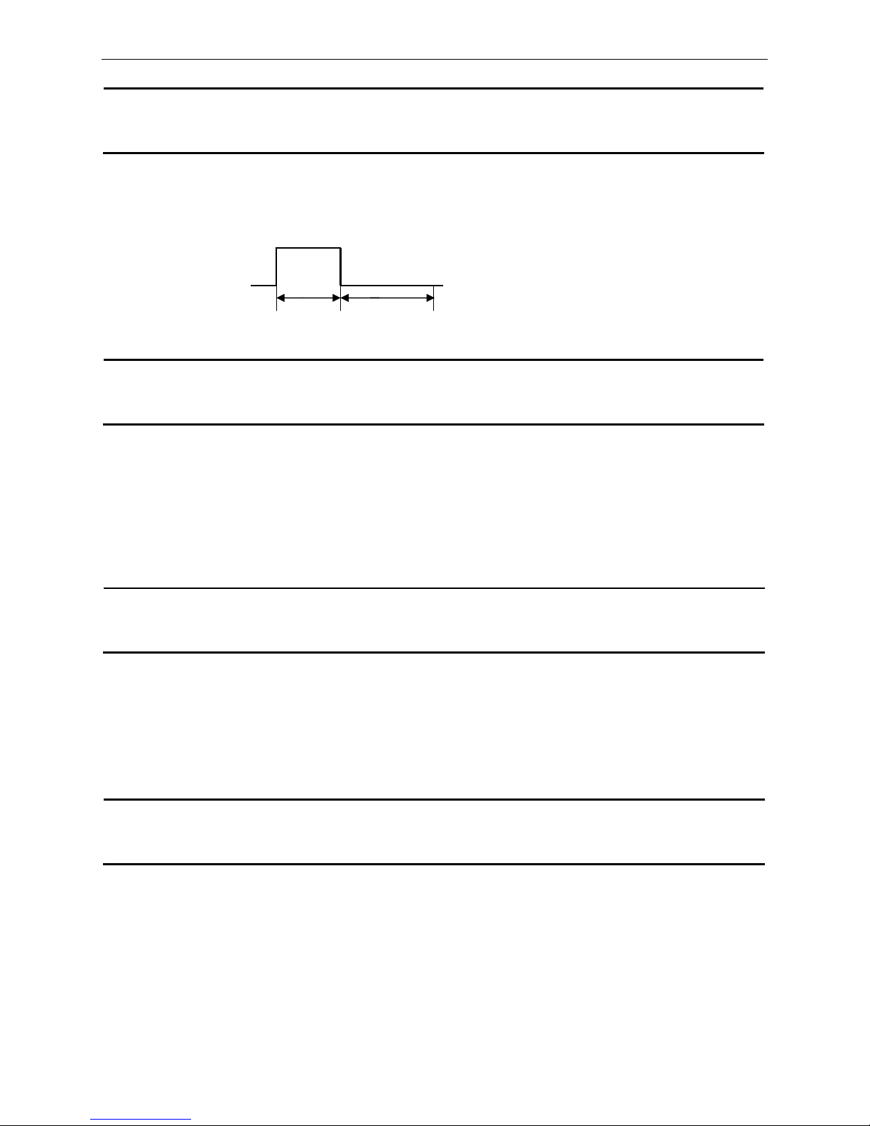
BP-007 User’s Manual
- 49 -
ESC p Generate cash drawer drive pulse
Format: ASCII: ESC p m n1 n2
Decimal: 27 112 m n1 n2
Hex: 1B 70 m n1 n2
[Description]
Generate cash drawer drive pulse.
M=0, 1, 48, 49; 0≤n1≤n2≤255
The format of pulse is shown as follows:
ESC v Transmit printer status
Format: ASCII: ESC v
Decimal: 27 118
Hex: 1B 76
[Description]
This command is effective by using serial interface, and its function is to transmit the status of paper sensor
as 1 byte of data. The signification of this byte is following:
When paper is out, bit2=1; When paper is in, bit2=0;
When black mark is effective, bit7=1 denotes that the current position is the black mark position; bit7=0
denotes that the current position is not the black mark position. If black mark is ineffective, this bit is
undefined.
FS ! Select Chinese character mode
Format: ASCII:
FS ! n
Decimal: 28 33 n
Hex: 1C 21 n
[Description]
The bit function of “n” is shown as follows:
bit2=0, double-height mode is disabled; bit2=1, double-height mode is enabled
bit3=0, double-width mode is disabled; bit3=1, double-width mode is enabled
bit7=0, underline is disabled; bit7=1, underline is enabled
[Default] n = 0
FS & Enter Chinese characters printing mode
Format: ASCII:
FS &
Decimal: 28 38
Hex: 1C 26
[Description]
When received this command, after finishing current line printing, the printer will change to Chinese
characters printing mode from next line.
Default mode is Chinese characters printing mode.
n1×2ms n2×2ms
Page 55

BP-007 User’s Manual
- 50 -
FS - Set Chinese underline mode
Format: ASCII: FS - n
Decimal: 28 45 n
Hex: 1C 2D n
[Description]
Turns on or off underline mode for Chinese characters, using n as follows:
When n=0, underline has no effect on Chinese characters;
When n=1, Chinese characters are set by single underline mode;
When n=2, Chinese characters are set by double underline mode, but the shift generated by “HT”
command is invalid.
FS 2 Self-define Chinese characters
Format: ASCII: FS 2 a1 a2 d1 d2 d3 …d32
Decimal: 28 50 248 a2 d1 d2 d3 …d32
Hex: 1C 32 F8 a2 d1 d2 d3 d32
[Description]
Define the user-defined Chinese characters.
a1=F8 (Hex); A1 ≤ a2 ≤ FE (Hex).
Chinese code has two bytes: a1 is the first byte and a2 is the second byte.
FS S Set full-size Chinese characters spacing
Format: ASCII: FS S n1 n2
Decimal: 28 83 n1 n2
Hex: 1C 53 n1 n2
[Description]
Set the left-side character spacing to n1 dots; Set the right-side character spacing to n2 dots. Half-size
characters will be put in good order automatically to ensure that the width of full-size character is twice that
of half-size character.
Default: n1=0, n2=2.
FS W Turn quadruple-size mode on/off for Chinese character
Format: ASCII: FS W n
Decimal: 28 87 n
Hex: 1C 57 n
[Description]
Turn quadruple-size mode on or off for multi-byte code character.
When n=<*******1>B, quadruple-size mode is turned on.
When n=<*******0>B, quadruple-size mode is turned off.
GS FF Executes black mark detecting
Format: ASCII: GS FF
Decimal: 29 12
Hex: 1D 0C
[Description]
Execute black mark detecting command. If black mark is detected, the printer stops feeding paper and
returns a value (AAH) by serial interface; If black mark is not detected, the printer feeds paper until to the
end of this page and returns a value (55H) by serial interface.
Page 56
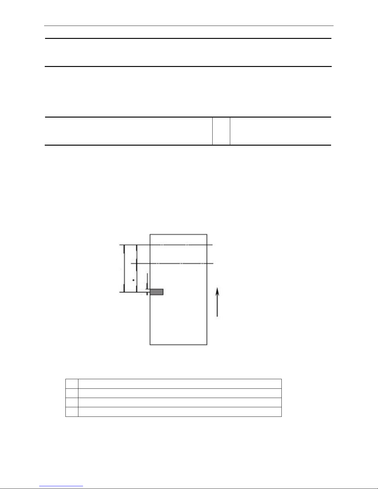
BP-007 User’s Manual
- 51 -
GS ( A Test command
Format: ASCII:
GS (
A pL pH n m
Decimal: 29 40 65 pL pH n m
Hex: 1D 28 41 pL pH n m
[Description]
pL=2, pH=0, n=0, m=1, 49
Enter HEX print mode (HEX DUMP)
To cancel this command, you must restart the printer.
GS ( F Set offset of black mark for printing and cutting position
Format: ASCII:
GS (
F pL pH a m nL nH
Decimal: 29 40 70 pL pH a m nL nH
Hex: 1D 28 46 pL pH a m nL nH
[Description]
The parameters set by this command will be valid even after the printer is restarted.
This command is used for selecting permission of orientation control by black mark and used for setting the
beginning print-position offset or tearing/cutting position offset from black mark. This value is calculated by
dots number.
The parameters of this command are shown as follows:
pL+ (pH×256) =4, that is: pL=4, pH=0
1≤a≤3,
m=0, 48
0≤ (nL+nH×256) < 1700
z a: set the different offset
a function
1 Set the beginning print-position offset from the black mark
2 Set the beginning tearing/cutting position offset from the black mark
3 Set the beginning print-position offset from the cutter
z m=0 or m=48, calculate the offset in the feed direction;
z nL、nH: The distance of offset is (nL+nH×256)×0.176mm; when a=3, 0≤nL≤246; nH=0.
z nL=nH=0,when the black mark was detected, the current print head’s position on the bill is the
Figure 7-1
A=67mm
C=29mm
Middle position of black
mark detector
2mm
Line position for cutting/tearing paper
Beginning printing position
A
Feeding direction
C
Page 57
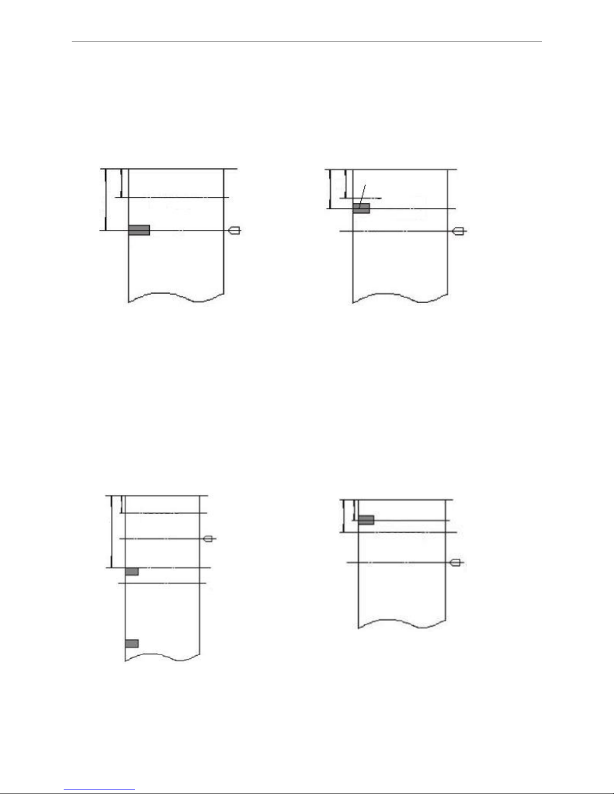
BP-007 User’s Manual
- 52 -
beginning print-position that is set, and the tearing/cutting position of the current bill is the
tearing/cutting position that is set.
z Calculation explanation for the tearing/cutting position offset and the beginning print-position offset
is shown as follows:
1. When the distance L of the tearing/cutting position offset from the black mark is same with the
inherent mechanical value L
0
of the printer, and the distance Q of the tearing/cutting position
offset from the beginning print-position is same with the inherent mechanical value Q
0
of the
printer (shown as figure 7-2), all the offset value set by “GS ( F” command is 0.
2. (1) When the distance L of the tearing/cutting position offset from the black mark is less than the
inherent mechanical value L
0
of the printer (shown as figure 7-3), the calculation of
tearing/cutting position offset is shown as follows:
tearing/cutting position offset =(L0-L)/0.176 (dots number)
(2) When the distance L of the tearing/cutting position offset from the black mark is greater than the
inherent mechanical value L0 of the printer (shown as figure 4), the calculation of tearing/cutting
position offset is shown as follows:
tearing/cutting position offset =(L
0
+ distance of adjacent two black mark -L)/0.176(dots number)
Note: When the tearing/cutting position offset is being set, the parameter “a” of “GS ( F”
command should be “2”.
3. When the tearing/cutting position offset is not zero, or the distance Q of the tearing/cutting position
offset from the beginning print-position is greater than the inherent mechanical value Q
0
of the
printer (shown as figure 7-5), the calculation of the beginning print-position offset by “GS ( F”
Figure 7-2
Figure 7-3
Figure 7-5
Figure 7-4
Black mark
detector
L=L
0
Q=Q
0
ABCDEFG
BCDEFGH
Black Mark
Tearing/cutting
position
Beginning
print-position
L<L
0
Q
ABCDEFG
BCDEFGH
Black Mark
Tearing/cutting
position
Black mark
detector
L>L
0
Q
ABCDEFG
BCDEFGH
Black Mark
Cutting/tearing position
Beginning print-position
Black mark detector
Cutting/tearing position
Cutting/tearing
position
Q>Q
0
L
ABCDEFG
BCDEFGH
Black Mark
Black mark
detector
Beginning
print-positio
Page 58

BP-007 User’s Manual
- 53 -
command is shown as follows:
the beginning print-position offset = (Q- Q
0
)/0.176+ tearing/cutting position offset
Note: When setting the beginning print-position offset, the parameter “a” of “GS ( F” command
should be “1”.
4. The inherent mechanical value
of the printer: L0=A (mm) Q0=C (mm) (shown as figure 7-1).
GS r Transmit printer status
Format: ASCII: GS r n
Decimal: 29 114 n
Hex: 1D 72 n
[Description]
This command is effective at serial interface.
If n=1 or n=49, paper status is returned. If paper is present, the bit2, 3 of the returned byte is 0; if paper is
not present, the bit 2, 3 of the returned byte is 1.
GS V Select cut mode and cut paper
Format: ASCII: GS V m n
Decimal: 29 86 m n
Hex: 1D 56 m n
[Description]
m=66, 0≤n≤255
When m=66, paper is fed to the position (cutting position + n*1/144 inch) and paper is cut partially (only
valid with auto-cutter type). But if the black mark is effective, the value of n is ineffective. The distance of
paper feed is decided by the command of “GS ( F”.
Format: ASCII: GS V m
Decimal: 29 86 m
Hex: 1D 56 m
[Description]
When m=1 or m=49, paper is fed to the cutting position and cut partially (only valid with auto-cutter type).
Page 59

BP-007 User’s Manual
- 54 -
Appendix Commands List
Control Code Hexadecimal Code Function
HT 09 Horizontal tab
LF 0A Print and line feed
CR 0D Print and carriage return
FF 0C Page mode print and return
ESC SP 1B 20 n Set right-side character spacing
ESC !
1B 21 n Select print mode (s)
ESC % 1b 25 n Select/cancel user-defined character set
ESC & 1B 26 s n m a d1..dn Define user-defined characters
ESC * 1B 2A m n1 n2 Select bit-image mode
ESC - 1B 2D n Turn underline mode on/off
ESC 2 1B 32 Set 1/6 inch line spacing
ESC 3 1B 33 n Set n/144 inch line spacing
ESC < 1B 3C Return home
ESC ? n 1B 3F n Cancel user-defined characters
ESC @ 1B 40 Initialize printer
ESC C 1B 43 n Set the page length according to line spacing
ESC D 1B 45 n1 … nk NULL Set horizontal tab positions
ESC E 1B 45 n Turn emphasized mode on/off
ESC G 1B 47 n Turn double-strike mode on/off
ESC J 1B 4A n Print and feed paper
ESC K 1B 4B n Print and reverse feed
ESC U 1B 55 n Turn unidirectional printing mode on/off
ESC c 4 n 1B 63 34 Select paper sensor (s) to stop printing
ESC c 5 n 1B 63 35 Enable/disable panel buttons
ESC d n 1B 64 n Print and feed n lines
ESC e n 1B 65 n Print and reversely feed n lines
ESC i 1B 69 Full cut
ESC j n 1B 6A n Print and reversely feed n/144 inch
ESC m 1B 6D Partial cut
ESC p m t1 t2 1B 6F Generate cash drawer pulse
ESC v 1B 76 Transmit printer status
FS !
1C 21 n Select Chinese character mode
FS & 1C 26 Set Chinese language mode
FS - 1C 2D n Turn Chinese characters underline on /off
FS . 1C 2E Cancel Chinese language mode
FS 2 1C 32 Define user-defined Chinese characters
FS S 1C 53 n1 n2 Set Chinese character spacing
FS W 1C 57 n Turn quadruple-size mode on/off for Chinese
characters
GS FF 1D 0C Print and eject label
GS ( A pL
pH n m
1D 28 41 pL pH n m Test command
Page 60

BP-007 User’s Manual
- 55 -
GS ( F pL
pH a m nL nH
1D 28 46 pL pH a
m nL nH
Set offset of black mark for printing and cutting position
GS r 1D 72 n Transmit status
GS V m n 1D 56 m n Select cut mode and cut paper
 Loading...