

BioZone Scientific International CoilCare, COILCARE X Installation Instructions And Operating Manual
COILCARE© X
Installation Instructions and Operating Manual
© 2017 BioZone Scientic International, Inc.
81200012B
CoilCare Series
IMPORTANT!
Thank you for purchasing BioZone Scientic’s CoilCare® ultraviolet light germicidal irradiation
disinfection system for commercial HVAC applications. CoilCare can keep HVAC evaporator
coils clear of contamination and biolm, allowing signicant savings in maintenance and energy
costs, while improving indoor air quality. CoilCare works by irradiating coil surfaces in germicidal
ultraviolet light. The UV light inactivates microorganisms and breaks down organic residue,
preventing growth and keeping coils clean and operating eciently. The system is equipped with
a UV lamp and a reector to direct and focus UV light on the coil surface. The water-resistant
power supply is easy to mount and can withstand the humid environments of HVAC enclosures.
The quantity and positioning of UV lamp modules is determined by several factors, including the
coil dimensions and other HVAC system design specications. Your BioZone Scientic commercial
UV specialist can help congure the best system for your application.
PROTECT EYES FRO M UV LIGHT
WARNING
TURN OFF UN IT OR DISCONNECT
BEFORE SE RVICING
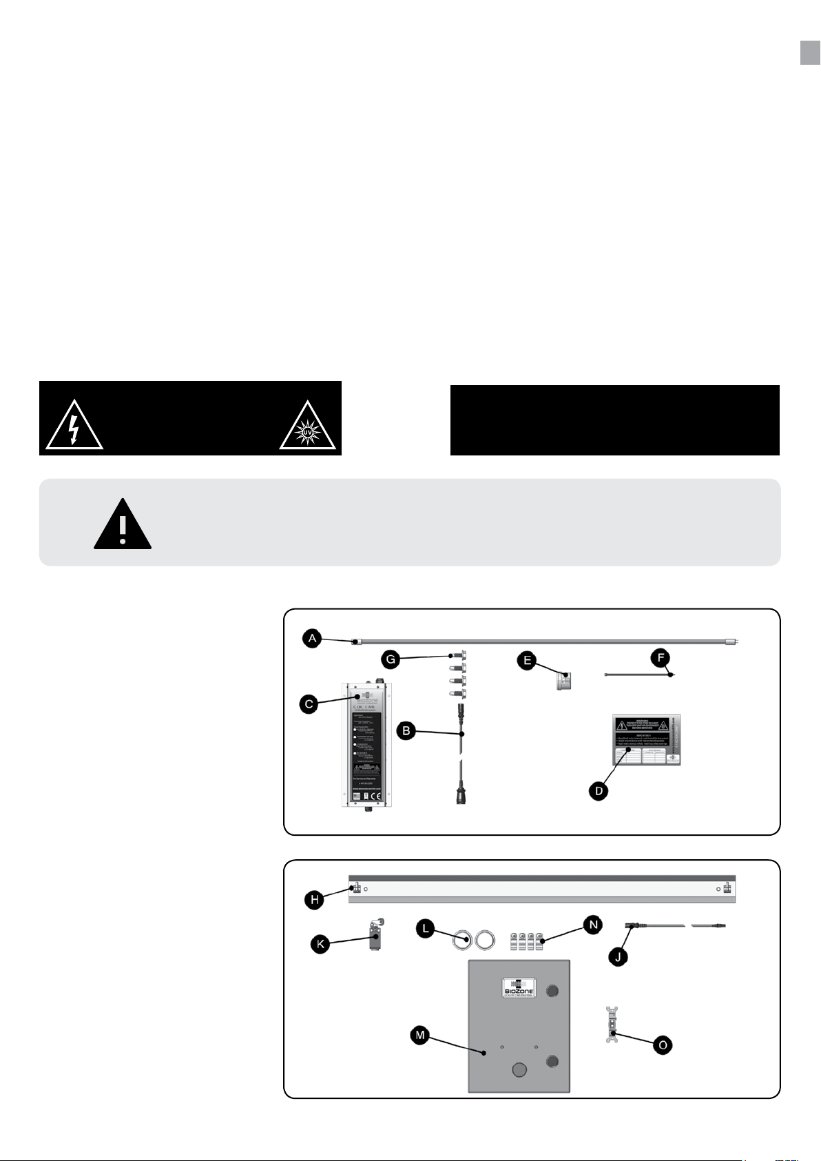
CCX Parts
A UV Lamp
B Lamp Connector
C Power Supply
D UV Warning Label
E Sight Glass
F Black Nylon Zip Ties
G Mounting Screws
Qualified technicians should install this product
•
Install in accordance with relevant building codes
•
• Read instructions carefully including safety warnings
BioZone CoilCare systems must be installed by certied technicians only.
Installation of this product by anyone other than licensed HVAC or electrical
contractors voids warranty, and BioZone assumes zero liability.
Optional Parts
G UV Reector
J Lamp Cable Extension 10ft
K Door Interlock Switch
L Contact Plates
M Control Box, Congurable
N Lamp Clip Pack
O Light Switch
2

SYSTEM CONFIGURATION GUIDELINES
1.
2.
Determine the dimensions of the evaporator
coils or area to be treated.
Use the guidelines below to select the
proper conguration and number of lamps
needed to treat the required dimensions.
CoilCare Conguration Guidelines
• Maximum germicidal eectiveness is within an 18in [457mm] radius from lamp
center axis
• The optimal distance between lamp(s) and the irradiated surface is 12in [305mm]
• The distance between stacked lamps should not exceed 35in [889mm]
• The distance between end to end lamps should not exceed 12in [305mm]
• The distance of lamp ends to the edge of irradiated surface should not exceed 6in
[152mm]
• Minimal germicidal eectiveness expected at/beyond 48in [1219mm] radius from
lamp center axis
• When coil depth is more than 12in [305mm], treating both sides of the coil may be
indicated
BioZone Scientic oers free
of charge UVCalc™ to assist
with system conguration and
selection. Contact your BioZone
commercial UV specialist for
more information.
12” [ 305 mm] max. space between lamps
6” [152 mm] max. space to end of coils
Overlap lamps where necessary
3
Recommendations for Eective CoilCare Installations
• Air Velocity: 400-500 fpm [2-2.5m/s] maximum
• Air Temperature: 40°F – 110°F maximum [4°C – 43°C]
• Lamp Distance from Coil: 6in – 48in [152mm – 1219mm]
• Electrical Wiring: compliant with local and national code, UL/ETL standards
• Safety Measures: alarms and disconnects, warning signage, employee training
• Lamp Disposal: in accordance with local and national regulations (see lamprecycle.org
for more information)
• Insulation Guidelines for Safety: the use of UV resistant materials such as aluminum
reectors, shielding, jacketing, and tape, may be indicated to protect non-UV-compatible
materials in the treatment area. Contact BioZone Scientic if specic questions arise
concerning material compatibility.
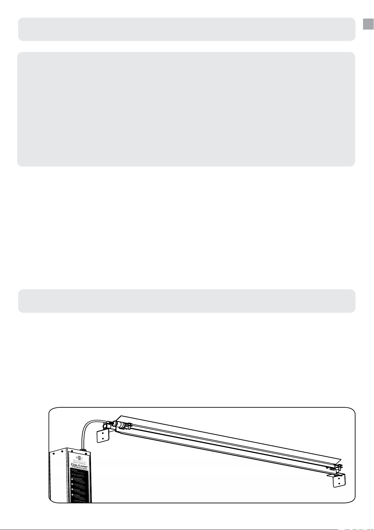
INSTALLATION INSTRUCTIONS
First, determine the ideal mounting location within the HVAC system, and then
congure the CoilCare system accordingly. CoilCare can be mounted to the air handler
wall or similar support several ways depending on the size, orientation, and distance
between the mounting surfaces and surfaces to be irradiated.
Contact your BioZone commercial UV specialist with any questions or concerns prior
to installation.
Install Framing
EMT/Conduit
1.
In most situations, when the system is mounted to surfaces perpendicular to the
surface to be irradiated, L-brackets are attached to the wall or support with selftapping screws.
Measure the distance between the L-brackets and cut tubing 1” less than the distance
between L-brackets. Extend the tubing between the L-brackets and fasten at each
end.
4
 Loading...