

BIOTRONIK SE and KG TACHNT2 Users Manual

Inlexa 3/7
ICD Family • Tachyarrhythmia Therapy • Cardiac Resynchronization Therapy
ICD-Familie • Tachyarrhythmietherapie • Kardiale Resynchronisationstherapie
Familia de DAI • Terapia antitaquiarritmia • Terapia de resincronización cardiaca
Famille des DAI • Traitement de la tachyarythmie • Traitement par resynchronisation cardiaque
Technical manual
Gebrauchsanweisung
Manual técnico
Manuel technique
• en
• de
• es
• fr
0123
0681 2016
© BIOTRONIK SE & Co. KG
All rights reserved. Specications subject
to modication, revision and improvement.
® All product names in use may be trademarks or
registered trademarks held by BIOTRONIK or
the respective owner.
16-D-xx
Revision: B (2015-11-06)
BIOTRONIK SE & Co. KG
Woermannkehre 1
12359 Berlin · Germany
Tel +49 (0) 30 68905-0
Fax +49 (0) 30 6852804
sales@biotronik.com
www.biotronik.com

en • English
Product Description . . . . . . . . . . . . . . . . . . . . . . . . . . . . . . . . . . . . . . . . . . . . . . . . . . . . . . 1
Intended Medical Use . . . . . . . . . . . . . . . . . . . . . . . . . . . . . . . . . . . . . . . . . . . . . . . 1
System Overview. . . . . . . . . . . . . . . . . . . . . . . . . . . . . . . . . . . . . . . . . . . . . . . . . . . 2
Therapeutic and Diagnostic Functions . . . . . . . . . . . . . . . . . . . . . . . . . . . . . . . . . 7
General Safety Instructions . . . . . . . . . . . . . . . . . . . . . . . . . . . . . . . . . . . . . . . . . . . . . . . . 8
Operating Conditions . . . . . . . . . . . . . . . . . . . . . . . . . . . . . . . . . . . . . . . . . . . . . . . 8
Possible Complications . . . . . . . . . . . . . . . . . . . . . . . . . . . . . . . . . . . . . . . . . . . . . 9
Possible Risks. . . . . . . . . . . . . . . . . . . . . . . . . . . . . . . . . . . . . . . . . . . . . . . . . . . . 10
Implantation. . . . . . . . . . . . . . . . . . . . . . . . . . . . . . . . . . . . . . . . . . . . . . . . . . . . . . . . . . . . 11
Implantation Procedure . . . . . . . . . . . . . . . . . . . . . . . . . . . . . . . . . . . . . . . . . . . . 11
Precautionary Measures while Programming . . . . . . . . . . . . . . . . . . . . . . . . . . 13
Magnet Response . . . . . . . . . . . . . . . . . . . . . . . . . . . . . . . . . . . . . . . . . . . . . . . . . 16
Follow-up . . . . . . . . . . . . . . . . . . . . . . . . . . . . . . . . . . . . . . . . . . . . . . . . . . . . . . . 16
Patient Information. . . . . . . . . . . . . . . . . . . . . . . . . . . . . . . . . . . . . . . . . . . . . . . . 17
Replacement Indications . . . . . . . . . . . . . . . . . . . . . . . . . . . . . . . . . . . . . . . . . . . 17
Explantation and Device Replacement . . . . . . . . . . . . . . . . . . . . . . . . . . . . . . . . 18
Parameters . . . . . . . . . . . . . . . . . . . . . . . . . . . . . . . . . . . . . . . . . . . . . . . . . . . . . . . . . . . . 18
Bradycardia / CRT. . . . . . . . . . . . . . . . . . . . . . . . . . . . . . . . . . . . . . . . . . . . . . . . . 18
Tachycardia . . . . . . . . . . . . . . . . . . . . . . . . . . . . . . . . . . . . . . . . . . . . . . . . . . . . . . 22
Sensing . . . . . . . . . . . . . . . . . . . . . . . . . . . . . . . . . . . . . . . . . . . . . . . . . . . . . . . . . 24
Diagnostics . . . . . . . . . . . . . . . . . . . . . . . . . . . . . . . . . . . . . . . . . . . . . . . . . . . . . . 24
Home Monitoring . . . . . . . . . . . . . . . . . . . . . . . . . . . . . . . . . . . . . . . . . . . . . . . . . 24
Technical Data . . . . . . . . . . . . . . . . . . . . . . . . . . . . . . . . . . . . . . . . . . . . . . . . . . . . . . . . . . 25
Mechanical Characteristics . . . . . . . . . . . . . . . . . . . . . . . . . . . . . . . . . . . . . . . . . 25
Electrical Characteristics. . . . . . . . . . . . . . . . . . . . . . . . . . . . . . . . . . . . . . . . . . . 25
Battery Data . . . . . . . . . . . . . . . . . . . . . . . . . . . . . . . . . . . . . . . . . . . . . . . . . . . . . 27
Legend for the Label . . . . . . . . . . . . . . . . . . . . . . . . . . . . . . . . . . . . . . . . . . . . . . 29
Table of Contents
1 Product Description
Intended Medical Use
Intended use
Inlexa belongs to a family of implantable cardioverter-defibrillators (ICD). The primary
objective of the therapy is to prevent sudden cardiac death. Furthermore, the device is
capable of treating bradycardia arrhythmias and cardiac resynchronization therapy
with multisite ventricular pacing.
The implantation of an ICD is a symptomatic therapy with the following objectives:
•
Termination of spontaneous ventricular fibrillation (VF) through shock delivery
•
Termination of spontaneous ventricular tachycardia (VT) through antitachycardia
pacing (ATP); in case of ineffective ATP or hemodynamically not tolerated VT, with
shock delivery
•
Cardiac resynchronization through multisite ventricular pacing (triple-chamber
devices)
•
Compensation of bradycardia through ventricular (single-chamber devices) or
AV sequential pacing (DX, dual- and triple-chamber devices).
VR-T DX and HF-T/HF-T QP devices types with DX functionality are only indicated
for patients not requiring atrial pacing.
Diagnosis and therapy forms
The device monitors the heart rhythm and automatically detects and treats cardiac
arrest resulting from ventricular tachyarrhythmia. All major therapeutic approaches
from the field of cardiology and electrophysiology are included. BIOTRONIK
Home Monitoring® enables physicians to perform therapy management at any time.
Required expertise
In addition to having basic medical knowledge, the user must be thoroughly familiar
with the operation and the operation conditions of a device system.
•
Only qualified medical specialists having this required special knowledge are
permitted to use implantable devices.
•
If users do not possess this knowledge, they must be trained accordingly.
en • English
1

Indications
Inlexa can treat life-threatening ventricular arrhythmias with antitachycardia pacing
and defibrillation.
Generally approved differential diagnostics methods, indications, and recommendations for ICD therapy apply to BIOTRONIK devices. See the current guidelines of
cardiology associations for guidance.
We recommend observing the indications published by the German Cardiac Society
(Deutsche Gesellschaft für Kardiologie, Herz- und Kreislaufforschung, (DGK)) and the
European Society of Cardiology (ESC). This also applies to the guidelines published by
the Heart Rhythm Society (HRS), the American College of Cardiology (ACC), the
American Heart Association (AHA), and other national cardiology associations.
Single-chamber and dual-chamber
Single-chamber and dual-chamber ICDs are indicated for patients with the following
risk:
•
Sudden cardiac death caused by ventricular arrhythmias
Triple-chamber
Triple-chamber ICDs are indicated for patients with the following risks:
•
Sudden cardiac death caused by ventricular arrhythmias
•
Congestive heart failure with ventricular asynchrony
Contraindications
Known contraindications:
•
Tachyarrhythmia caused by temporary or reversible irritation, e.g. poisoning, electrolyte imbalance, hypoxia, sepsis or acute myocardial infarction
•
Such frequent VT or VF that the therapies would cause an unacceptably rapid
depletion of the device batteries
•
VT with few or without clinically relevant symptoms
•
VT or VF treatable by surgery
•
Concomitant diseases that would substantially limit a positive prognosis
•
Accelerated intrinsic rhythm
System Overview
Device family
The complete Inlexa 3/7 device family consists of several device types with a DF-1/IS-1
or DF4/IS-1 connection or with DF4/IS-1 or DF4/IS4/IS-1 connection.
•
Single-chamber: VR-T and VR-T DX (device type with only a DF-1/IS-1 connection)
•
Dual-chamber: DR-T
•
Triple-chamber: HF-T and HF-T QP
Note:
Not all device types are included in every device family.
Note:
Not all device types are available in every country.
Note:
Not all device types are approved in every country.
Note:
Not all functions and parameters mentioned in this technical manual are
featured by each device type of each device family.
Device
The device's housing is made of biocompatible titanium, welded from outside and thus
hermetically sealed. The ellipsoid shape facilitates implantation in the pectoral muscle
area.
The connections for bipolar pacing and sensing (and unipolar connections for the triplechamber device) as well as for shock delivery are found in the device header.
The housing serves as a potential antipole during shock delivery or in the case of
unipolar lead configuration.
2
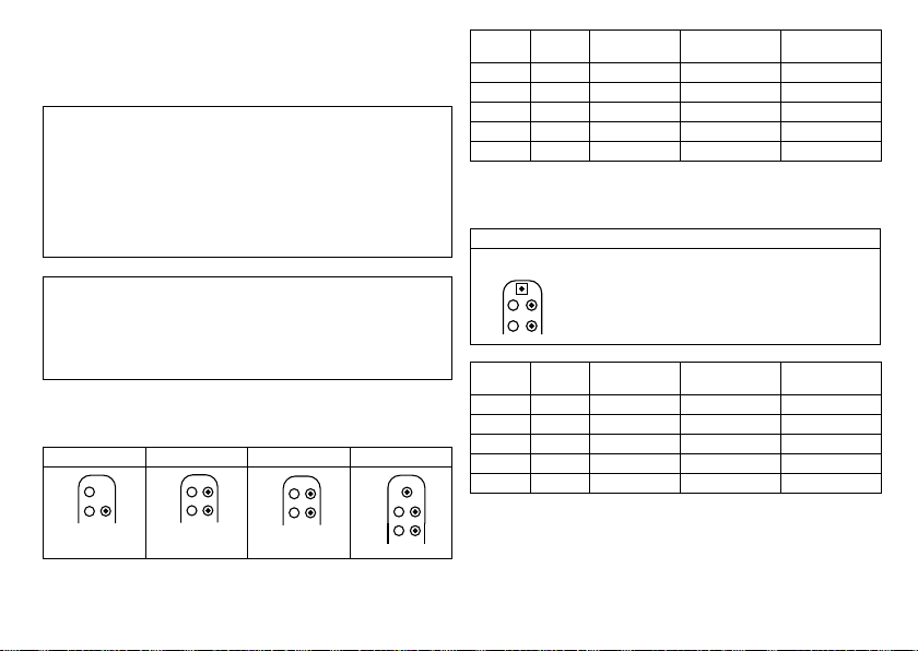
Lead connectors
DF-1
RV
SVC
DF-1
IS-1
RA
IS-1
RV
DF-1
RV
SVC
DF-1 IS-1
RA
IS-1
RV
DF-1
RV
SVC
DF-1
IS-1
RA
IS-1
RV
LV
IS-1
BIOTRONIK offers ICDs with headers for different standardized lead connections:
•
DF-1/IS-1 and DF-1/IS-1/IS4
•
DF4, DF4/IS-1 and DF4/IS-1/IS4
Note:
Suitable leads must comply with the norms:
•
A device's DF-1 connector port may only be used for connecting leads with a
DF-1 connector that conform to ISO 11318.
•
A device's IS-1 connector port may only be used for connecting leads with a
IS-1 connector that conform to ISO 5841-3.
•
A device's DF4 connector port may only be used for connecting leads with a
DF4 connector that conform to ISO 27186.
•
A device's IS4 connector port may only be used for connecting leads with a
IS4 connector that conform to ISO 27186.
Note:
The device and leads have to match.
•
Only DX type leads by BIOTRONIK may be connected to the device type VR DX with
DF-1/IS-1.
•
Only quadripolar leads may be connected to the device type HF QP with IS4.
•
When working with DX functionality, the device type HF (QP) with DF-1 (7 series)
may be connected to DX type leads by BIOTRONIK.
DF-1/IS-1
The labeling on each device provides information pertaining to the connector port
assignment in the header.
VR VR DX DR HF
DF-1
SVC
DF-1
RV
en • English
IS-1
RV
Connector
Lead
port
Configuration Implantation site Device type
connector
RA IS-1 Bipolar Atrium VR DX, DR, HF
RV IS-1 bipolar Right ventricle VR, VR DX, DR, HF
RV DF-1 Shock coil Right ventricle VR, VR DX, DR, HF
SVC DF-1 Shock coil Superior vena cava VR, VR DX, DR, HF
LV IS-1 Unipolar, bipolar Left ventricle HF
DF-1/IS-1/IS4
The labeling on each device provides information pertaining to the connector port
assignment in the header.
HF QP
IS4-LLLL
LV
DF-1
SVC
DF-1
RV
Connector
port
IS-1
RA
IS-1
RV
Lead
Configuration Implantation site Device type
connector
RA IS-1 Bipolar Atrium HF QP
RV IS-1 Bipolar Right ventricle HF QP
RV DF-1 Shock coil Right ventricle HF QP
SVC DF-1 Shock coil Superior vena cava HF QP
LV IS4 Unipolar, bipolar Left ventricle HF QP
3
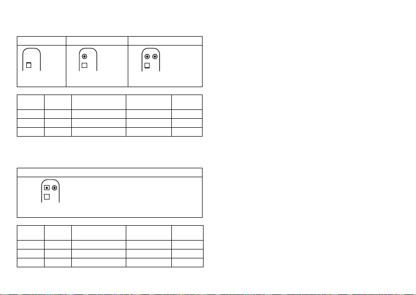
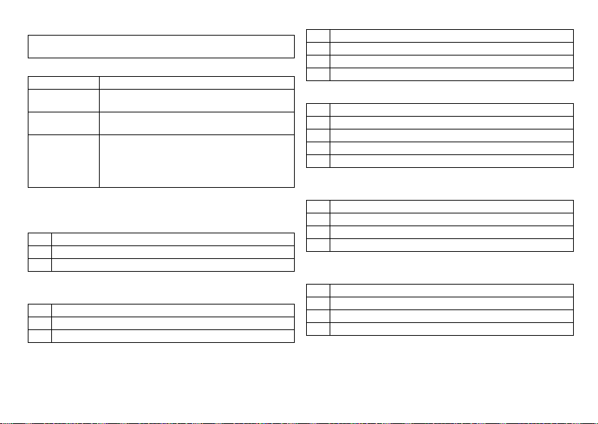
DF4/IS-1
The labeling on each device provides information pertaining to the connector port
assignment in the header.
VR DR HF
DF4-LLHH
RV
Connector
port
IS-1
RA
DF4-LLHH
RV
Lead
Configuration Implantation site Device type
connector
IS-1
RA
DF4-LLHH
RV
IS-1
LV
RA IS-1 Bipolar Atrium DR, HF
RV DF4 Bipolar and shock coil Right ventricle VR, DR, HF
LV IS-1 Unipolar, bipolar Left ventricle HF
DF4/IS-1/IS4
The labeling on each device provides information pertaining to the connector port
assignment in the header.
HF QP
IS4-LLLL IS-1
LV
Connector
port
DF4-LLHH
RV
Lead
connector
RA
Configuration Implantation site Device type
RA IS-1 Bipolar Atrium HF QP
RV DF4 Bipolar and shock coil Right ventricle HF QP
LV IS4 Unipolar, bipolar Left ventricle HF QP
Leads
BIOTRONIK leads are sheathed with biocompatible silicone. They can be flexibly
maneuvered, are stable long-term, and are equipped for active or passive fixation. They
are implanted using a lead introducer set. Some leads are coated with polyurethane
which is known to increase the sliding properties for the lead. Leads with steroids
reduce inflammatory processes. The fractal design of the electrodes provides for low
pacing thresholds. BIOTRONIK provides adapters to connect already implanted leads to
new devices.
Telemetry
Telemetric communication between the device and the programmer can be carried out
following initialization either by applying the programming head (PGH) to the device or
by using wireless radio frequency (RF) telemetry in the programmer. BIOTRONIK calls
this function SafeSync.
Programmer
Implantation and follow-up are performed with BIOTRONIK's portable programmer:
Software PSW as of version 1505.
There are programmers with integrated or external SafeSync Module for RF telemetry.
Leadless ECG, IEGM, markers and functions are displayed simultaneously on the color
display.
The programmer allows you to determine the thresholds and to perform all tests
during an in-office follow-up; in addition, you can change the permanent program and
send it to the implanted device.
In addition to this, the programmer is used to set mode and parameter combinations,
as well as for interrogation and saving of data from the device.
4
Modes
Note:
Not all functions and parameters mentioned in this technical manual are
featured by each device type of each device family.
The mode setting depends on the individual diagnosis:
Device type Modes
VR VVI; VVIR; VOO; OFF
7 series: VR DX VDD; VDDR; VDI; VDIR; VVI; VVIR; V00; OFF
DR, HF (QP) DDD; DDDR; DDI; DDIR
NBD and NBG codes
VVE is the NBD code for the antitachycardia mode of the single-chamber, dualchamber, and triple-chamber devices without atrial therapy:
V Shock in the ventricle
V Antitachycardia pacing (ATP) in the ventricle
E Detection via IEGM analysis
VDE is the NBD code for the antitachycardia mode of the dual-chamber and triplechamber devices with atrial therapy:
V Shock in the ventricle
D Antitachycardia pacing (ATP) in the atrium and ventricle
E Detection via IEGM analysis
7 series: VVI-CLS
VVI-CLS
7 series: DDDR-ADIR; DDD-ADI
VDD; VDDR; VDI; VDIR
VVI; VVIR; AAI; AAIR; VOO; DOO; OFF
7 series: VVI-CLS; DDD-CLS
DDDR is the NBG code for the antibradycardia mode of the dual-chamber devices:
D Pacing in the atrium and ventricle
D Sensing in the atrium and ventricle
D Pulse inhibition and pulse triggering
R Rate adaptation
DDDRV is the NBG code for the antibradycardia mode of the triple-chamber devices:
D Pacing in the atrium and ventricle
D Sensing in the atrium and ventricle
D Pulse inhibition and pulse triggering
R Rate adaptation
V Multisite pacing in both ventricles
VDDR is the NBG code for the antibradycardia mode of the single-chamber type DX
device:
V Ventricular pacing
D Sensing in the atrium and ventricle
D Pulse inhibition and pulse triggering
R Rate adaptation
VVIR is the NBG code for the antibradycardia pacing modes of the single-chamber
device:
V Ventricular pacing
V Sensing in the ventricle
I Pulse inhibition in the ventricle
R Rate adaptation
en • English
5
BIOTRONIK Home Monitoring
In addition to effective pacing therapy, BIOTRONIK provides a complete therapy
management system:
•
With Home Monitoring, diagnostic and therapeutic information as well as technical
data are automatically sent to a stationary or mobile transmitter via an antenna in
the device header. The data are encrypted and sent from the transmitter to the
BIOTRONIK Service Center via the cellular phone network.
•
The received data are deciphered and evaluated. Each physician can set the criteria
for evaluation to be used for each patient and can configure the time of notification
via e-mail, SMS or fax.
•
A clear overview of the results of this analysis is displayed for the attending physicians on the protected Internet platform Home Monitoring Service Center (HMSC).
•
Data transmission from the device is performed with a daily device message.
•
Device messages which indicate special events in the heart or in the device are
forwarded immediately.
•
A test message can be initiated at any time using the programmer to immediately
check the Home Monitoring function.
®
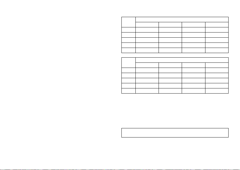
Inlexa order numbers
Not all device types are available in every country:
Inlexa 3
DF-1/IS-1 DF4/IS-1 DF-1/IS4/IS-1 DF4/IS4/IS-1
VR-T 404703 404704 — —
VR-T DX————
DR-T 404701 404702 — —
HF-T 404699 404700 — —
HF-T QP — — 416037 416038
Inlexa 7
DF-1/IS-1 DF4/IS-1 DF-1/IS4/IS-1 DF4/IS4/IS-1
VR-T 404643 404644 — —
VR-T DX 404642 — — —
DR-T 404640 404641 — —
HF-T 404636 404637 — —
HF-T QP — — 404638 404639
Package contents
The storage package includes the following:
•
Sterile packaging with device
•
Serial number label
•
Patient ID card
•
Warranty booklet
Note:
The technical manual pertaining to the device is either included in hard copy
form in the storage package or in digital form on the internet.
The sterile container includes the following:
•
Device, blind plugs (if applicable)
•
Screwdriver
6

Therapeutic and Diagnostic Functions
Diagnostic functions
•
Data from implantation and the most recent interrogations and follow-ups are
recorded as well as arrhythmia episodes; they are stored together with other data
to assess both the patients' and the device's state at any time.
•
To check the lead for proper functioning, an automatic impedance measurement
using subthreshold pacing pulses is performed in the device.
•
Leadless ECG function: For all device types, far-field derivation can be measured
without external leads between the right ventricular shock coil and housing, which,
depending on the implantation site, corresponds to ECG derivation II or III
(Einthoven).
•
Once a telemetry connection has been established during a test procedure in an inoffice follow-up, the leadless ECG and the IEGM are displayed with markers.
Antitachycardia pacing
•
The ICD can treat ventricular tachycardia with antitachycardia pacing (ATP); ATP
can also be delivered in the VF zone (ATP One Shot) when the stability criterion
(monomorphic rapid VTs) is met before shock delivery.
•
The ICD can also respond to atrial tachycardia with antitachycardia pacing (ATP) in
case of stable heart rates or with high-rate pacing (HF bursts) in case of unstable
heart rates.
•
Depending on the device type, the device program contains not only the ICD
functions but also all pacemaker functions for 1, 2 or 3 chambers. The heart rhythm
is continuously monitored; each arrhythmia is classified according to the heart rate
and the adjustable detection criteria. Depending on the preset values, antibradycardia as well as antitachycardia therapy is inhibited or delivered.
Cardioversion, defibrillation
•
The ICD can treat ventricular tachyarrhythmia with cardioversion and/or defibrillation. Shock polarity and energy can be programmed individually. Shock energies
between 2.0 J and 40 J are possible. Before delivery of the shock, the ICD can be set
to only deliver a shock when ongoing tachyarrhythmia is confirmed; during this
time period the device can identify spontaneous conversion of the tachyarrhythmia
and cancel the charging process if necessary.
•
The shock paths can be set between the different shock coils (SVC/RV) and/or the
housing.
Antibradycardia pacing and CRT
•
Rate hystereses, automatic sensor functions, and a night program promote the
patient's intrinsic rhythm, avoid overdrive pacing, and facilitate adaptation of the
device to the individual needs of the patient.
•
Both atrial and ventricular thresholds are determined automatically in the device.
For the 7 series, capture control is used to set the pulse amplitudes so that pacing
is performed with the optimum atrial and ventricular amplitude for the patients
with each change of the pacing threshold.
•
Setting an upper tracking rate for the atrium prevents unspecific atrial pacing, thus
reducing the risk of pacemaker-mediated tachycardia.
•
Positive AV hysteresis functions support intrinsic conduction and thus the natural
contraction sequence. Negative AV hysteresis functions support the cardiac resynchronization therapy by maintaining pacing in stress situations.
•
For resynchronization of the ventricles, triple-chamber implants have functions for
multisite pacing with possible VV delays in either direction.
•
To ensure that no additional surgery is necessary in case of a left-sided increase of
pacing threshold or undesired phrenic nerve stimulation, different pacing polarities
can be set for the left ventricular lead with a triple-chamber device. Up to
12 vectors can be used with the HF QP device type.
•
With the HF QP device of the 7 series: Two stimuli can be configured for the left
ventricle with a view to improve the resonchronization of the ventricles. The stimuli
can be delivered sequentially or simultaneously.
•
Additional, special form of rate adaptation with devices from the 7 series: an
increased cardiac output requirement is detected using physiological impedance
measurement. The measuring principle is based on contractile changes (ionotropy)
of the myocardium (CLS function: Closed Loop Stimulation). Rate adaptation is
automatically initialized and optimized in CLS mode.
•
Ventricular pacing suppression with devices from the 7 series: unnecessary
ventricular pacing is avoided by promoting intrinsic conduction (Vp suppression
function). The device can thereby adapt to conduction changes and switch between
an ADI(R) and a DDD(R) mode.
en • English
7

Storing programs
There are different therapy programs:
•
Parameter settings effective for the most common indications in pre-configured
programs (Program Consult).
•
For special indications, individual parameter settings can be stored in up to three
therapy programs.
Home Monitoring functions
•
The device automatically sends information to the transmitter once a day. It also
sends messages related to events, which are immediately forwarded to the Service
Center. In addition to this, test messages can be initiated using the programmer.
•
Appointments for Home Monitoring-supported follow-ups can be scheduled via the
HMSC.
•
Important medical information in the device messages include the following:
—
Atrial and ventricular arrhythmias
—
Parameters relevant to leads in the atrium and ventricle: pacing thresholds,
sensing amplitudes, impedances
—
Current statistics
—
IEGM online HD with up to 3 high definition channels
2 General Safety Instructions
Operating Conditions
Technical manuals
The following technical manuals provide information about usage of the device
systems:
— Technical manual for the device
— Technical manual for the HMSC
— Technical manuals for leads
— Technical manuals for the programmer and its accessories
— Technical manuals for the user interface
— Technical manuals for cables, adapters and accessories
•
Technical manuals are either included in hard copy form in the storage package or
in digital form on the internet: manuals.biotronik.com.
•
Follow all relevant technical manuals.
•
Reserve technical manuals for later use.
Care during shipping and storage
•
Devices must not be stored or transported close to magnets or sources of electromagnetic interference.
•
Note the effects of the storage duration; see Battery Data.
Delivery in shipment mode
The device is delivered in shipment mode to protect the battery; capacitor reforming
required during storage could result in controlled extended charge times of the shock
capacitors.
•
The shipment mode is displayed on the programmer after the initial interrogation
(it is deactivated during implantation by the first valid (in-range) measurement of
the pacing impedance).
Temperature
Extremely low and high temperatures affect the service time of the battery in the
device.
•
Permitted for shipping and storage are +5°C to +45°C.
8
 Loading...