

BIOTRONIK SE and KG ICD4200 Users Manual

Acticor 7 ProMRI
ICD Family | Tachyarrhythmia Therapy |
Cardiac Resynchronization Therapy
Technical Manual
439128
Revision: C
© BIOTRONIK SE & Co. KG
All rights reserved.
Specifications subject to modification, revision and improvement.
® All product names in use may be trademarks or registered trademarks held by
BIOTRONIK or the respective owner.
0123
2018
Index 439129Technical ManualActicor 7
BIOTRONIK SE & Co. KG
Woermannkehre 1
12359 Berlin · Germany
Tel +49 (0) 30 68905-0
Fax +49 (0) 30 6852804
sales@biotronik.com
www.biotronik.com

2
Table of Contents
Table of Contents
Table of Contents
Product Description . . . . . . . . . . . . . . . . . . . . . . . . . . . . . . . . . . . . . . . . . . . . . 3
Intended Medical Use. . . . . . . . . . . . . . . . . . . . . . . . . . . . . . . . . 3
System Overview. . . . . . . . . . . . . . . . . . . . . . . . . . . . . . . . . . . . . 5
Therapeutic and Diagnostic Functions . . . . . . . . . . . . . . . . . . . 9
General Safety Instructions. . . . . . . . . . . . . . . . . . . . . . . . . . . . . . . . . . . . . . 11
General information on safe handling of the device . . . . . . . 11
Operating Conditions . . . . . . . . . . . . . . . . . . . . . . . . . . . . . . . . 13
Possible Complications . . . . . . . . . . . . . . . . . . . . . . . . . . . . . . 14
Possible Risks. . . . . . . . . . . . . . . . . . . . . . . . . . . . . . . . . . . . . . 16
Implantation . . . . . . . . . . . . . . . . . . . . . . . . . . . . . . . . . . . . . . . . . . . . . . . . . . 18
Implantation Procedure . . . . . . . . . . . . . . . . . . . . . . . . . . . . . . 18
Precautionary Measures while Programming . . . . . . . . . . . . 22
Magnet Response. . . . . . . . . . . . . . . . . . . . . . . . . . . . . . . . . . . 26
Follow-up . . . . . . . . . . . . . . . . . . . . . . . . . . . . . . . . . . . . . . . . . 27
Patient Information. . . . . . . . . . . . . . . . . . . . . . . . . . . . . . . . . . 28
Replacement Indications . . . . . . . . . . . . . . . . . . . . . . . . . . . . . 29
Explantation and device replacement. . . . . . . . . . . . . . . . . . . 30
Parameter . . . . . . . . . . . . . . . . . . . . . . . . . . . . . . . . . . . . . . . . . . . . . . . . . . . . 31
Tachycardia. . . . . . . . . . . . . . . . . . . . . . . . . . . . . . . . . . . . . . . . 31
Sensing . . . . . . . . . . . . . . . . . . . . . . . . . . . . . . . . . . . . . . . . . . . 34
Bradycardia / CRT. . . . . . . . . . . . . . . . . . . . . . . . . . . . . . . . . . . 35
Home Monitoring . . . . . . . . . . . . . . . . . . . . . . . . . . . . . . . . . . . 40
Diagnostics . . . . . . . . . . . . . . . . . . . . . . . . . . . . . . . . . . . . . . . . 41
MRI program. . . . . . . . . . . . . . . . . . . . . . . . . . . . . . . . . . . . . . . 42
Technical Data . . . . . . . . . . . . . . . . . . . . . . . . . . . . . . . . . . . . . . . . . . . . . . . . 43
Mechanical Characteristics. . . . . . . . . . . . . . . . . . . . . . . . . . . 43
Electrical Characteristics . . . . . . . . . . . . . . . . . . . . . . . . . . . . 44
Battery Data . . . . . . . . . . . . . . . . . . . . . . . . . . . . . . . . . . . . . . . 46
Legend for the Label . . . . . . . . . . . . . . . . . . . . . . . . . . . . . . . . 48

3
Product Description
Intended Medical Use
1 Product Description
Product Description1439129Technical ManualActicor 7
Intended Medical Use
Intended use
Diagnosis and therapy forms
Indications
Acticor belongs to a family of implantable cardioverter-defibrillators (ICDs). The
primary objective of the therapy is to prevent sudden cardiac death. Furthermore,
the device is capable of treating bradycardia arrhythmias and cardiac resynchronization therapy with multisite ventricular pacing.
The implantation of an ICD is a symptomatic therapy with the following objectives:
• Termination of spontaneous ventricular fibrillation (VF) through shock delivery
• Termination of spontaneous ventricular tachycardia (VT) through antitachycardia pacing (ATP); in case of ineffective ATP or hemodynamically not tolerated
VTs, with shock delivery
• Cardiac resynchronization through multisite ventricular pacing (triple-chamber
devices)
• Compensation of bradycardia through ventricular (single-chamber devices) or
AV sequential pacing (DX, dual- and triple-chamber devices).
VR-T DX and HF-T/HF-T QP devices types with DX functionality are only
indicated for patients not requiring atrial pacing.
The device monitors the heart rhythm and automatically detects and treats cardiac
arrest resulting from ventricular tachyarrhythmia. All major therapeutic
approaches from the field of cardiology and electrophysiology are included.
BIOTRONIK Home Monitoring enables physicians to perform therapy management
at any time.
Acticor can treat life-threatening ventricular arrhythmias with antitachycardia
pacing and defibrillation.
Generally approved differential diagnostics methods, indications, and recommendations for ICD therapy apply to BIOTRONIK devices. See the current guidelines of
cardiology associations for guidance.
We recommend observing the indications published by the German Cardiac Society
(Deutsche Gesellschaft für Kardiologie, Herz- und Kreislaufforschung, (DGK)) and
the European Society of Cardiology (ESC). This also applies to the guidelines
published by the Heart Rhythm Society (HRS), the American College of Cardiology
(ACC), the American Heart Association (AHA), and other national cardiology associations.
Single-chamber and
dual-chamber
Triple-chamber
Single-chamber and dual-chamber ICDs are indicated for patients with the
following risk:
• Sudden cardiac death caused by ventricular arrhythmias
Triple-chamber ICDs are indicated for patients with the following risks:
• Sudden cardiac death caused by ventricular arrhythmias
• Congestive heart failure with ventricular asynchrony

4
Product Description
Intended Medical Use
Contraindications
Known contraindications:
• Tachyarrhythmia caused by temporary or reversible irritation, e.g. poisoning,
electrolyte imbalance, hypoxia, sepsis or acute myocardial infarction
• Such frequent VT or VF that the therapies would cause an unacceptably rapid
depletion of the device batteries
• VT with few or without clinically relevant symptoms
• VT or VF treatable by surgery
• Concomitant diseases that would substantially limit a positive prognosis
• Accelerated intrinsic rhythm

System Overview
5
Product Description
System Overview
Device family
Device
The complete device family Acticor 7 consists of several device types with a DF4/IS1 or DF4/IS-1/IS4 connection.
The following device variants are available:
Device type Variant with Home Monitoring
Single-chamber Acticor 7 VR-T ProMRI
Acticor 7 VR-T DX ProMRI
Dual-chamber Acticor 7 DR-T ProMRI
Triple-chamber Acticor 7 HF-T ProMRI
Acticor 7 HF-T QP ProMRI
Note: Not all device types are included in every device family.
Note: Not
Note: Not
Note: Not
featured in each device type of each device family.
The device's housing is made of biocompatible titanium, welded from outside and,
therefore, hermetically sealed. The ellipsoid shape facilitates implantation in the
pectoral muscle area.
The connections for bipolar pacing and sensing (and unipolar connections for the
triple-chamber device) as well as for shock delivery are found in the device header.
The housing serves as a potential antipole during shock delivery or in the case of
unipolar lead configuration.
all device types are available in every country.
all device types are approved in every country.
all functions and parameters mentioned in this technical manual are
Device type with DF4
connection only
Lead connectors
BIOTRONIK offers ICDs with headers for different standardized lead connections.
• DF4, DF4/IS-1 and DF4/IS4/IS-1
Note: Suitable leads must comply with the norms.
• A device's DF4 connector port may only be used
connector that conform to ISO 27186.
• A device's IS4 connector port may only be
connector that conform to ISO 27186.
• A device's IS-1 connector port may only be used for connecting leads with an IS1 connect
Note: The devic
•Only DX leads for DF4 by BIOTRONIK may be co
with DF4.
• When working with DX functionality, DX leads for DF4 by BIOTRONIK may be
onnected to the device type HF and the device type HF QP with DF4.
c
• Only quadripolar leads may be connected to the device type HF QP with IS4.
or that conform to ISO 5841-3.
e and leads have to match.
for connecting leads with a DF4
used for connecting leads with a IS4
nnected to the device type VR DX
6
Product Description
System Overview
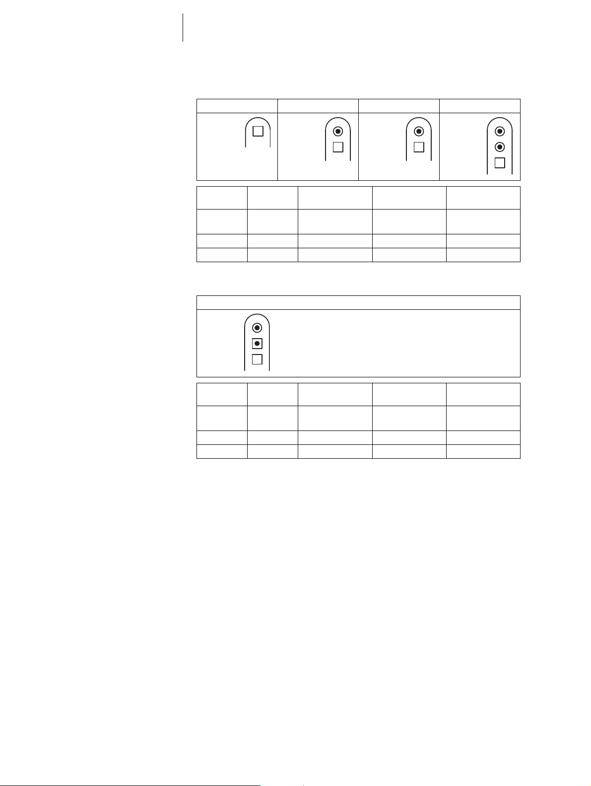
DF4/IS-1
DF4/IS4/IS-1
The labeling on each device provides information pertaining to the connector port
location in the header:
VR VR DX DR HF
RV:
DF4-LLHH
Connector
port
RA:
IS-1 BI
RV:
DF4-LLHH
Lead
connector
Configuration Implantation site Device type
RA:
IS-1 BI
RV:
DF4-LLHH
RV DF4 Bipolar and shock
Right ventricle VR, DR, DX, HF
RA:
IS-1 BI
LV:
IS-1 UNI/BI
RV:
DF4-LLHH
coil
RA IS-1 Bipolar Atrium DR, HF
LV IS-1 Unipolar, bipolar Left ventricle HF
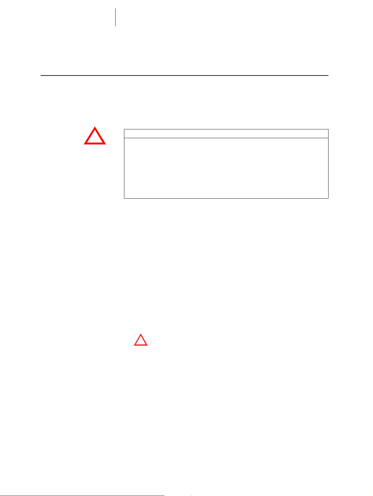
The labeling on each device provides information pertaining to the connector port
location in the header:
HF QP
RA:
IS-1 BI
LV:
IS4-LLLL
RV:
DF4-LLHH
Leads
Telemetry
Connector
port
RV DF4 Bipolar and shock
Lead
connector
Configuration Implantation site Device type
Right ventricle HF QP
coil
LV IS4 Unipolar, bipolar Left ventricle HF QP
RA IS-1 Bipolar Atrium HF QP
BIOTRONIK leads are sheathed with biocompatible silicone. They can be flexibly
maneuvered, are stable long-term, and are equipped for active or passive fixation.
They are implanted using a lead introducer set. Some leads are coated with polyurethane which is known to increase the sliding properties for the lead. Steroideluting leads reduce inflammatory processes. The fractal design of the electrodes
provides for low pacing thresholds.
BIOTRONIK provides a series of adapters to connect a variety of already implanted
leads to new devices.
Telemetric communication between the device and the programmer is intialized
either by applying the programming head (PGH) to the device or by using wireless
wandless telemetry in the programmer.

7
Product Description
System Overview
Programmer
Modes: overview
Implantation and follow-ups are performed with the portable BIOTRONIK
programmer using the PSW software version 1801.A or higher.
The programmer contains an integrated module for wandless telemetry.
Leadless ECG, IEGM, markers and functions are displayed simultaneously on the
color display.
The programmer allows for the determination of thresholds and the performance of
all tests during an in-office follow-up; furthermore, you can change the permanent
program and send it to the implanted device.
In addition, the programmer is used to set mode and parameter combinations, as
well as for interrogation and saving of data from the device.
Note: Not all functions and parameters mentioned in this technical manual are
featured in each device type of each device family.
he mode that should be programmed depends on individual diagnosis. The
Note: T
possible modes that can be programmed specific to each device type are listed in
the tables with the order numbers.
Device type Modes Standard
VR
VR DX VDD; VDDR; VDI; VDIR; VVI-CLS; VVI; VVIR;
VVI-CLS; VVI; VVIR; V00; AUS VVI
VVI
V00; AUS
DR, HF (QP) DDD-CLS; DDD; DDDR; DDD-ADI;
DDD
DDDR-ADIR; DDI; DDIR; D00; VDD; VDDR;
VDI; VDIR; VVI-CLS; VVI; VVIR; V00; AAI; AAIR;
OFF
NBD and NBG codes
VVE is the NBD code for the antitachycardia mode of the single-chamber, dualchamber, and triple-chamber devices without atrial therapy:
V Shock in the ventricle
V Antitachycardia pacing (ATP) in the ventricle
E Detection via IEGM analysis
VDE is the NBD code for the antitachycardia mode of the dual-chamber and triplechamber devices with atrial therapy:
V Shock in the ventricle
D Antitachycardia pacing (ATP) in the atrium and ventricle
E Detection via IEGM analysis
DDDR is the NBG code for the antibradycardia pacing mode of the dual-chamber
device:
D Pacing in the atrium and ventricle
D Sensing in the atrium and ventricle
D Pulse inhibition and pulse triggering
R Rate adaptation
DDDRV is the NBG code for the antibradycardia pacing mode of the triple-chamber
device:
D Pacing in the atrium and ventricle
D Sensing in the atrium and ventricle
D Pulse inhibition and pulse triggering
R Rate adaptation
V Multisite pacing in both ventricles

8
BIOTRONIK Home Monitoring®In addition to effective pacing therapy, BIOTRONIK provides a complete therapy
Product Description
System Overview
VDDR is the NBG code for the antibradycardia mode of the single-chamber type DX
device:
V Ventricular pacing
D Sensing in the atrium and ventricle
D Pulse inhibition and pulse triggering
R Rate adaptation
VVIR is the NBG code for the antibradycardia modes of the single-chamber device:
V Ventricular pacing
V Sensing in the ventricle
I Pulse inhibition in the ventricle
R Rate adaptation
management system:
• With Home Monitoring, diagnostic and therapeutic information, as well as technical data of the device, are automatically an
via an antenna in the device header. The data is encrypted and sent from the
transmitter to the BIOTRONIK Service Center via the cellular phone network.
• The received data is deciphered and eva
criteria for evaluation to be used for each patient and can configure the time of
notification via e-mail, SMS or fax.
• A clear overview of the results of this analysis is displayed for the attending
ysicians on the protected internet platform Home Monitoring Service Center
ph
MSC).
(H
• Data transmission from the device is performed with a daily device
• Device messages that indicate special cardiac or device related events are
transmitted immediately.
• A test message can be initiated at any tim
ately check the Home Monitoring function.
d wirelessly sent to a transmitter
luated. Each physician can set the
message.
e using the programmer to immedi-
Acticor order numbers
Package contents
Not all device types are available in every country:
Device type Lead connection Number of
Acticor series 7
VR-T DF4 1 VVE-VVIR 429526
VR-T DX DF4/IS-1 2 VVE-VDDR 429525
DR-T DF4/IS-1 2 VDE-DDDR 429524
HF-T DF4/IS-1/IS-1 3 VDE-DDDRV 429523
HF-T QP DF4/IS4/IS-1 3 VDE-DDDRV 429522
The storage package includes the following:
• Sterile packaging with device
• Serial number label
• Patient ID card
• Warranty booklet
Note: The t
form in the storage package or is available in digital form on the internet.
The sterile container includes the following:
• Device, blind plugs (if applicable)
•Screwdriver
echnical manual pertaining to the device is either included in hard copy
connector
ports
Mode Order number

9
Product Description
Therapeutic and Diagnostic Functions
Therapeutic and Diagnostic Functions
Diagnostic functions
Antitachycardia pacing
• Data from implantation and the most recent interrogations and follow-ups are
recorded as well as arrhythmia episodes; they are stored together with other
data to assess both the patients' and the device's state at any time.
• To check the lead for proper functioning, an automatic impedance measurement using subthreshold pacing pulses is performed in the device. Continuous
impedance measurements of the shock paths and the pacing polarities of the
lead improve the determination of lead failures.
RV
• Leadless ECG function: For all device types, far-field derivation can be
measured without external leads between the right ventricular distal shock coil
and housing, which, depending on the implantation site, corresponds to ECG
derivation
• Once a telemetry connection has been established during a test procedure in an
in-office follow-up, the leadless ECG and the IEGM are displayed with markers.
• The ICD can treat ventricular tachycardia with antitachycardia pacing (ATP); ATP
can also be delivered in the VF zone (ATP
(monomorphic rapid
• The ICD can also respond to atrial tachycardia with antitachycardia pacing (ATP)
in case of stable heart rates or with high-rate pacing (HF bursts) in case of
unstable heart rates.
• Depending on the device type, the device software contains not only the ICD
functions but also all pacemaker functions for 1, 2 or 3 chambers. The heart
rhythm is continuously monitored; each arrhythmia is classified according to
the heart rate and the adjustable detection criteria. Depending on the preset
values, antibradycardia as well as antitachycardia therapy is inhibited or deliv
ered.
II or III (Einthoven).
One Shot) when the stability criterion
VTs) is met before shock delivery.
-
Cardioversion, defibrillation
Antibradycardia pacing
• The ICD can treat ventricular tachyarrhythmia with cardioversion and/or defibrillation. Shock polarity and energy can be programmed individually. Shock
energies between 2.0
ICD can be set to only deliver a shock when ongoing tachyarrhythmia is
confirmed; during this time period the device can identify spontaneous conversion of the tachyarrhythmia and cancel the charging process if necessary.
• The shock paths can be set between the different shock coils (SVC/RV) and/or
the housing.
• Rate hystereses, automatic sensor functions, and a night program promote the
patient's intrinsic rhythm, avoid overdrive pacing, and facilitate adaptation of the
device to the individual needs of the patient.
• Both atrial and ventricular thresholds are determined automatically in the
device. Additionally, capture control is used to set the pulse amplitudes so that
pacing is performed with the optimum atrial and ventricular amplitude for the
patients with each change of the pacing threshold.
• Setting an upper tracking rate for the atrium prevents unspecific atrial pacing,
thus reducing the risk of pacemaker-mediated tachycardia.
• Positive AV hysteresis functions support intrinsic conduction and thus the
natural contraction sequence. Negative AV hysteresis functions support the
cardiac resynchronization therapy by maintaining pacing in stress situations.
• Additional, special form of rate adaptation: an increased cardiac output requirement is detected using physiological impedance measurement. The measuring
principle is based on contractile changes (ionotropy) of the myocardium (CLS
function: Closed loop stimulation). Rate adaptation is automatically initialized
and optimized in CLS mode.
• Ventricular pacing suppression: unnecessary ventricular pacing is avoided by
promoting intrinsic conduction (Vp suppression function). The device can
J and 40 J are possible. Before delivery of the shock, the

10
Product Description
Therapeutic and Diagnostic Functions
thereby adapt to conduction changes and switch between an ADI(R) and a
DDD(R) mode.
Cardiac resynchronization
therapy, CRT
Storing programs
ProMRI devices recognize
magnetic resonance imaging
devices
• For resynchronization of the ventricles, triple-chamber devices have functions
for multisite ventricular pacing with possible VV delays in either direction.
• To ensure that no additional surgery is necessary in case of a left-sided increase
of pacing threshold or undesired phrenic nerve stimulation, different pacing
polarities can be set for the left ventricular lead with a triple-chamber device.
Up to 20
• With the HF QP device type: Two stimuli can be configured for the left ventricle
to improve the resynchronization of the ventricles. The stimuli can be delivered
sequentially or simultaneously.
• The effectiveness of resynchronization can be improved if intrinsic AV delays
exist: The function CRT AutoAdapt measures the intracardiac conduction times
every minute, sets up the pacing configuration on BiV or LV (with activated LV
capture control) and adapts the AV delay automatically.
There are different therapy programs:
• Parameter settings effective for the most common pacemaker indications are
offered in pre-configured programs (ProgramConsult).
• For individual programs, parameter settings can be stored in up to 3 therapy
programs.
The static magnetic field of an MRI scanner is reliably recognized with the aid of a
sensor. The sensor can be activated for a maximum of 14 days using the
MRI AutoDetect function during an in-office follow-up.
If the patient comes near an MRI scanner within the time set, the device recognizes
the static magnetic field and automatically activates the preset MRI program.
Reprogramming to the permanent program occurs also automatically when the
imaging device is left.
vectors can be used with the HF QP device type.
Home Monitoring functions
• The device automatically sends information to the transmitter once a day. It also
sends messages related to events, which are immediately forwarded to the
Service Center. In addition to this, test messages can be initiated using the
programmer.
• Important medical information in the device messages include the following:
— Atrial and ventricular arrhythmias
— Parameters relevant to leads in the atrium and ventricle: pacing thresholds,
sensing amplitudes, impedances
— Current statistics
—IEGM online HD with up to 3 high definition channels
• The following remote functions are possible via HMSC:
— Appointments for Home Monitoring-supported follow-ups can be
scheduled.
— Current device data can be requested by the HMSC using the QuickCheck
function. Provided that the patient is in the vicinity of the transmitter
(CardioMessenger), data usual for Home Monitoring-supported follow-up
are compiled, an IEGM is added, and data transfer takes place in a timely
manner; this process is called interrogation on demand and usually runs
within a maximum of 15
minutes.
11
!
!
General Safety Instructions
General information on safe handling of the device
2 General Safety Instructions
General Safety Instructions2439129Technical ManualActicor 7
General information on safe handling of the device
Follow notes and instructions
WARNING
Risk to patient, risk to doctor and interferences of device
Cardiac electrotherapy is subject to specific conditions. From the transport to the
storage, what concerns sterility, what concerns technical complications, what
requires special care while implanting or what to follow with regard to risky
therapies in persons who have a pacemaker: The device system is sensitive and
must not be damaged, in order not to harm patients.
• It is always necessary that all information in this as well as related technical
manuals must be taken note of and followed.
Safety instructions and
warnings in this technical
manual
This technical manual provides safety-relevant information on several topics:
• On the one hand, there are general safety warnings, which are basically valid. In
this technical manual, the main topics are as below:
— General information on the safe h
— Operating Conditions
— Possible technical complications
— Possible medical complications
• On the other hand, there are special and general warnings regarding the
plantation, which educate about actions and provide instructions for safe
im
working. In this technical manual, the main topics are as below:
— Implantation procedure
— Precautionary measures while programming
—Follow-up
— Patient information
— Replacement Indications
— Explantation and device replacement
Warnings have been particularly indicated in this technical manual
•
!
with a symbol and a signal word: Non
!
can cause injury or even death to the patient.
andling of the product
-compliance with the instructions

12
General Safety Instructions
General information on safe handling of the device
Technical manuals
Required expertise
The following technical manuals provide information about safe usage of the device
systems:
— Technical manual for the device
— Technical manual for the HMSC
— Technical manuals for leads
— Technical manuals for the programmer and its accessories
— Technical manuals for the user interface of the programmer
— Technical manuals for cables, adapters and accessories
— ProMRI - MR Manual Conditional device systems
• Technical manuals are either included in hard copy form in the storage package
or available in digital form on the Internet:
https://manuals.biotronik.com
• Follow all relevant technical manuals.
• Keep technical manuals for later use.
In addition to having basic medical knowledge, the user must be thoroughly familiar
with the operation and the operation conditions of a device system.
• Only qualified medical specialists who have this required special knowledge are
permitted to use implantable devices.
• If users do not possess this knowledge, they must be trained accordingly.

13
!
!
Operating Conditions
General Safety Instructions
Operating Conditions
WARNING
Risk to patient and interferences of device
Cardiac electrotherapy is subject to special operating conditions. If these are not
fulfilled, the functionality of the device may be impaired; if the functionality of the
device is impaired, the patient may be at risk.
• Please observe all operating conditions.
Care during
shipping and storage
Delivery in shipment mode
Temperature during
shipping and storage
Sterile delivery
Sterile packaging
Single use only
No electromagnetic interferences should occur in the vicinity of devices.
• Devices must not be stored or transported close to magnets or sources of electromagnetic interference.
• Note the effects of the storage dura
The device is delivered in shipment mode to protect the battery; capacitor reforming
required during storage could result in controlled extended charge times of the
shock capacitors.
• The shipment mode is displayed on the programmer after the initial interrogation (it is deactivated during implantation – after transmission of the first
program – by the first valid (in-range) measurement o
Extremely low and high temperatures affect the service time of the battery in the
device.
• Permitted for shipping and storage are +5°C to +45°C.
The device and the screwdriver are delivered gas-sterilized. Sterility is guaranteed
only if the blister and quality control seal have not been damaged.
The device and screwdriver are packaged together in two separately sealed blisters.
The inner blister is also sterile on the outside so that it can be transferred in a
sterile state during implantation.
In order that infection risks are excluded, the device is intended for single use only.
• Do not use the device if the package is damaged.
• The device must not be resterilized and reused.
Even the screwdriver is intended for single use only.
tion; see Battery Data.
f the pacing impedance).

14
!
!
Possible Complications
General Safety Instructions
Possible Complications
WARNING
Risk to patient and interferences of device
Cardiac electrotherapy may be subject to special complications. They must be
considered, so that the functionality of the device is not impaired and as a result,
that patients are not at risk.
• Please take all safety information carefully into account.
General information on
medical complications
Skeletal myopotentials
Possible technical failures
Complications for patients and device systems generally recognized among
practitioners also apply to BIOTRONIK devices.
• Normal complications may include fluid accumulation within the device pocket,
infections, or tissue reactions. Primary sources of complication information
include current scientific and technological knowledge.
• It is impossible to guarantee the efficacy of antitachycardia therapy, even if the
program
ical examinations. In rare cases the
is possible for therapies to induce or accelerate tachycardia and cause
sustained ventricular flutter or fibrillation.
Bipolar sensing and control of sensitivity are adapted by the device to the rate range
of intrinsic events so that skeletal myopotentials are usually not recorded. Skeletal
myopotentials can nonetheless be classified as intrinsic events especially at very
high sensing sensitivity and, depending on the interference, may cause inhibition or
antiarrhythmia therapy.
In the case of undesired myopotentials, the device switches to asynchronous pacing
if the interference rate is exceeded.
• Where appropriate, carry out a follow-up and evaluate the sensitivity and the
pacing mode.
Technical failure of a device system cannot be entirely ruled out. Possible causes
can include the following:
• Lead dislodgement, lead fracture
• Insulation defects
• Device component failures
• Battery depletion
• Interrupted telemetry
s have proven successful during tests or subsequent electrophysiolog-
set parameters may become ineffective. It
Electromagnetic interference
(EMI)
Any device can be sensitive to interference if external signals are sensed as intrinsic
rhythm or if measurements prevent rate adaptation:
• BIOTRONIK devices have been designed so that their susceptibility to EMI is
minimal.
• Due to the intensity and variety of EMI, there is no guarantee for safety. It is
lly assumed that EMI produces only minor symptoms, if any, in patients.
genera
• Depending on the pacing mode and the type
ence may lead to pulse inhibition or trig
dent pacing rate or asynchronous pacing.
• Under unfavorable conditions, for example du
procedures, interference sources may induce such a high level of energy into
the pacing system that the cardiac tissue surrounding the lead tip is damaged.
• Always evaluate the setting of sensing an
of interference, sources of interfer-
gering, an increase in the sensor-depen-
ring therapeutic or diagnostic
d triggered pacing mode.

15
General Safety Instructions
Possible Complications
Device behavior in case of EMI
Static magnetic fields
In case of electromagnetic interference, the device switches to asynchronous
pacing for as long as the interference rate is exceeded.
The magnetic sensor in the device detects magnetic fields starting at a magnetic
flux density of approximately 1.5 mT. Magnetic fields below 1 mT do not affect the
sensor.
 Loading...